Abstract
Type I and II halogen bonds are well-recognized motifs that commonly occur within crystals. Quantum calculations are applied to examine whether such geometries might occur in their closely related chalcogen bond cousins. Homodimers are constructed of the R1R2C=Y and R1R2Y monomers, wherein Y represents a chalcogen atom, S, Se, or Te; R1 and R2 refer to either H or F. A Type II (T2) geometry wherein the lone pair of one Y is closely aligned with a σ-hole of its partner represents a stable arrangement for all except YH2, although not all such structures are true minima. The symmetric T1 geometry in which each Y atom serves as both electron donor and acceptor in the chalcogen bond is slightly higher in energy for R1R2C=Y, but the reverse is true for R1R2Y. Due to their deeper σ-holes, the latter molecules engage in stronger chalcogen bonds than do the former, with the exception of H2Y, whose dimers are barely bound. The interaction energies rise as the Y atom grows larger: S < Se < Te.
1. Introduction
Halogen bonds (XB) bear a striking resemblance to the more commonly observed and thoroughly studied H-bond (HB). As has been deduced over many years [1,2,3,4,5,6,7,8,9,10,11], the latter is stabilized in large measure by an electrostatic attraction between the partial positive charge on the bridging proton of the acid and a negative region on the base, typically a lone pair. Therefore, the replacement of this H by a more electronegative X atom would at first sight seem counterintuitive, as one might initially conclude that the interaction ought to be repulsive. However, this paradox is resolved by the inspection of the disposition of the electrostatic potential about the X center, which includes a negative equator region surrounding a positive pole along the extension of the R-X bond, which can in turn attract the nucleophile. Due to its depletion of electron density, this latter positive region is commonly dubbed a σ-hole. As in the HB, the electrostatic attraction is complemented by other factors, most notably a charge transfer from the lone pair of the nucleophile to the σ*(RX) antibonding orbital of the Lewis acid unit [12,13,14,15,16,17,18,19,20,21,22,23,24,25].
There have been numerous observations of XBs within the context of crystals over the years, encompassing close encounters between an X atom and a nucleophile. Of particular interest have been those in which the atom of the nucleophile which most closely approaches X is itself a halogen atom [26,27,28,29,30,31,32,33,34,35,36,37,38,39]. An example of such an X··X halogen bond is illustrated in Figure 1a for the FBr dimer, where the σ-hole of the Lewis acid on the left is indicated by a positive conical region which is also coincident with the σ*(BrF) orbital. One of the Br lone pairs on the base unit is illustrated by a negative region which is aligned with the positive σ-hole, as well as the σ*(BrF) orbital for optimal charge transfer. This sort of arrangement is commonly referred to as Type II (T2) in the crystallography literature.
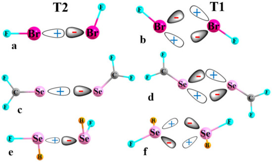
Figure 1.
Diagrams depicting the alignment between positively charged σ-hole of one unit with a negative lone pair of its partner in T2 and T1 arrangements of halogen bonds in (a,b); chalcogen bonds between sp2 Y atoms are shown in (c,d), while (e,f) portray sp3 hybridizations.
This configuration contrasts with T1 in Figure 1b, which is much more symmetrical with approximately equal FBr··Br angles. While the bending of the two molecules away from T2 deteriorates the alignment of the σ-hole of the molecule on the left and the lone pair on the right relative to T2, it also leads to a second and converse partial alignment of the lone pair on the left with a σ-hole on the right. Recent calculations [40] have shown that this pair of distorted XBs in T1 is only slightly less stable than the perfectly aligned single XB in T2. In fact, T1 does not represent a true minimum for the potential energy surface of this dimer, but is rather a transition state for the conversion of the T2 pictured in Figure 1a with its converse, where the two molecules reverse their role of electron donor and acceptor [40]. However, importantly, the energy difference between T2 and T1 is quite small, on the order of only 1 kcal/mol or less, for a wide selection of FX1··X2F dimers. It is because of this small energy difference that there have been nearly as many observations of T1-like geometries of X··X contacts within crystals as for the slightly more stable T2.
The widespread occurrence of both T1 and T2 structures leads to the obvious question as to whether such competitive geometries are limited to only halogen-bonded systems. The recent literature is replete with many observations of the very closely related chalcogen bonds (YBs), where X is replaced by S, Se, or Te [14,41,42,43,44,45,46,47,48,49,50,51,52,53,54,55,56,57]. Just as halogen atoms are typically univalent, the most common bonding pattern around a given Y chalcogen atom is divalent. In one such pattern, sp2 Y engages in a double bond with C, as in analogues to formaldehyde. One would expect a σ-hole on the Y, lying along the extension of the C=Y bond, flanked by a pair of lone pairs within the molecular plane. This sort of molecule can potentially form homodimers of both T2 and T1 type, much akin to XBs, as illustrated in Figure 1c,d, respectively, for the F2CSe homodimer.
The chalcogen atom can forsake a double bond, engaging instead in a pair of single bonds, as in YR1R2. This variation leads to not one but two σ-holes, one along the extension of each of the two YR bonds. The two lone pairs within this sp3 Y hybridization lie above and below the plane of the molecule. The T2 sort of classical chalcogen bond in Figure 1e for the SeFH homodimer aligns one of the Se σ-holes of the Lewis acid on the left with one of the two Se lone pairs of the base on the right. The T1 arrangement in Figure 1f again contains the essential elements of a duo of distorted YBs (this formulation is fundamentally unchanged if the two Y lone pairs arise from an alternate sp2 hybridization, with an occupied p-orbital perpendicular to the molecular plane, representing one of the lone pairs).
The work described below considers the potential of both T2 and T1 structures to serve as valid geometrical motifs for Y··Y chalcogen bonds in a fashion parallel to XBs. Units examined contain both sp2 and sp3 hybridizations of the Y atom, via R1R2C=Y and R1R2Y, where R1 and R2 refer to either H or the strongly electronegative F. Y atoms span the chalcogen family: S, Se, and Te. Homodimers of each of these molecules are examined to determine the stabilities of both T1 and T2 arrangements. Issues of concern include first whether such geometries constitute true minima on the potential energy surface, and how their stabilities compare with one another. Taking into account that most YBs in the literature are heterogeneous, in that the electron donor atom is much more electronegative than S, Se, or Te, how strong are the homogeneous Y··Y chalcogen bonds considered here? Is there a difference between S, Se, and Te with regard to these issues? Another question relates to how the substitution of H by F affects the binding, and how the overall energetics vary along the S, Se, Te sequence. Can one relate the stabilities of the T1 and T2 isomers, and their energy difference, to the maxima and minima of the electrostatic potential surrounding each monomer? As another issue, the bulk of earlier studies of chalcogen bonds include a highly electronegative atom such as O or N, or even an anion, as the electron donor. Consideration of YBs between pairs of like chalcogen atoms are much rarer. The work described below considers a much less electronegative chalcogen atom as both donor and acceptor.
2. Materials and Methods
Quantum chemical calculations were performed in the context of the DFT formulation, applying the M06-2X functional [58], which has been shown to be an accurate means of treating noncovalent bonds of the sort of interest here [59,60,61,62,63,64,65,66]. A polarized triple-ζ def2-TZVP basis set was chosen so as to afford a large and flexible set that can capture some of the more subtle charge rearrangements. Geometries were fully optimized, except where restrictions were imposed as described below. The Gaussian 16 [67] program was used as the primary medium to conduct these computations.
The interaction energy Eint of each homodimer was calculated as the difference between the energy of the complex and the sum of the energies of the two subunits, each in the geometry they adopt within the dimer. The counterpoise procedure [68] was applied to correct basis set superposition error of Eint. Maxima and minima of the molecular electrostatic potential (MEP) on the ρ = 0.001 au isodensity surface of each monomer were identified via the Multiwfn program [69]. Atoms in Molecules (AIM) bond paths and their associated critical points were located and their densities evaluated with the aid of the AIMAll program [70]. Natural Bond Orbital (NBO) charge transfer energies [71,72] were assessed through the aid of the NBO program incorporated into Gaussian.
3. Results
3.1. Monomer Properties
The molecular electrostatic potential (MEP) surrounding the X atom in a molecule such as FX is relatively simple. There is a single positive σ-hole directly along the extension of the FX axis. This pole is complemented by a negatively charged equatorial region that rings the X atom, associated with the three X lone pairs. There are two sorts of chalcogen-containing molecules considered here. The Y chalcogen atom is double-bonded to a single C atom in the R1R2C=Y series, wherein R1 and R2 refer to either F or H. There is a σ-hole along the C=Y projection, as evident by the blue regions on the right side of Figure 2a–c for Y=Se. When both substituents are H, they are not quite electronegative enough to produce a true σ-hole, and the maximum, shallow as it is, actually lies above the plane of the molecule. The two lone pairs of Y are a prominent cause of the two minima shown in red, one on either side of the Se atom.
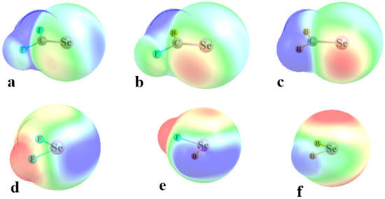
Figure 2.
MEPs on the 0.001 au isodensity surface surrounding monomers with blue and red indicating positive and negative potentials, respectively. These extrema refer to +13 and −19 kcal/mol for (a–c), and to +25 and −13 kcal/mol for (d–f).
The values of the MEP on the ρ = 0.001 au isodensity surface are contained in the upper half of Table 1, and they followed certain trends. The σ-hole deepened as the Y atom grew in size from S to Se to Te, while the MEP minimum had little sensitivity to the identity of the Y atom. Replacing the electron-withdrawing F substituents with H attenuated the MEP maxima, sensible in light of the lesser ability of H to draw density toward itself. This same inability of H enabled the Y atom to retain a greater share of density, which added to the negative potential around its lone pairs in the MEP minima. These patterns are evident from the differing shading of red and blue as one progresses from Figure 1a–c.

Table 1.
Values of the maxima and minima (kcal/mol) of the MEP lying on the ρ = 0.001 au isodensity surface.
The change in geometry around the Y atom in the simpler R1R2Y molecules altered the disposition of the MEP extrema. There were two separate σ-holes, one lying along the projection of each RY bond; one of these is evident in Figure 1d,e, although this hole is absent in SeH2. The minima were again largely coincident with the Y lone pairs, so lay above and below the molecular plane. The trends in the MEP extrema in the lower half of Table 1 again follow rules according to atomic electronegativity. Again, the σ-holes deepened as the Y atom grew larger, while the minima were insensitive to Y size. The inability of H to attract electron density left the σ-holes in YH2 rather shallow, and the minima deepened as each F was replaced by H. There is one apparent anomaly in Table 1, in that the σ-holes of YFH and YF2 are quite similar. This paradox is easily resolved by a glance at Figure 2e, which shows that the σ-hole opposite the F is reinforced by the neighboring positive region surrounding the H atom (there is a second σ-hole along the HY projection of YFH, but this one is much shallower than the one lying opposite the F).
3.2. Geometries and Energetics
For each pair of homodimers, a search was carried out on the potential energy surface to determine whether geometries of the T1 or T2 type were minima. In several of these dyads, this was not the case and one or more geometry restrictions were needed in order to obtain structures of this type. For example, the SeCF2 T2 dimer required that the electron donor Se atom be restricted to the plane of the acceptor molecule, and the SeCHF and SeCH2 T2 geometries placed the donor Se atom squarely along the extension of the acceptor CSe axis. Some of the T1 structures could be realized only if the two CY··Y angles were forced to be equal to one another, although the value of that angle was optimized. Any geometry restrictions that were imposed are indicated by the footnotes in Table 2 that display the intermolecular R(Y··Y) distances.
Table 2.
Intermolecular R(Y··Y) (Å) distances (Å) in optimized homodimers.
Figure 3 presents illustrative geometries for the SeCR1R2 cases, with T2 and T1 geometries displayed on the left and right sides, respectively. The Se··Se distances lay between 3.51 and 3.86 Å, and there were no clear rules as to whether T1 or T2 had the longer of the two. The comparable structures of the SeR1R2 homodimers are exhibited in Figure 4. The R(Se··Se) distances were about 2.6–3.0 Å, with two exceptions. In the first place, the FSe··Se YB in Figure 4b was replaced by a pair of FSe··F YBs as the F is a much stronger electron donor than Se, reinforced by the much more negative MEP surrounding the F atom in Figure 2d. This swapping out of the electron donor from Y to F led to long R(Y··Y) distances in the YF2 T1 structures. The very weak character of the intermolecular interaction between SeH2 molecules in Figure 4e resulted in a particularly long separation for this as well as those for S and Te. Indeed, there was no T2 structure for this homodimer, even with geometry restrictions.
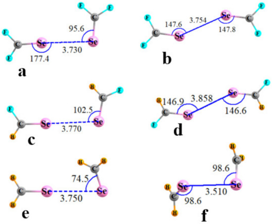
Figure 3.
Optimized geometries of homodimers of R1R2C=Se. T2 structures in (a,c,e); T1 in (b,d,f). Distances in Å, angles in degs.
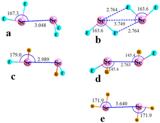
Figure 4.
Optimized geometries of homodimers of R1R2Se. T2 structures in (a,c); T1 in (b,d,e). Distances in Å, angles in degs.
The counterpoise-corrected interaction energies of the various dyads are reported in Table 3. Most of these interactions for the R1R2CY homodimers were fairly weak, less than 1 kcal/mol. The exceptions arose for some of the Te-complexes, as well as SeCH2, but even here these quantities remained below 3 kcal/mol. The complexes containing the simpler R1R2Y units were bound much more strongly, some exceeding 10 kcal/mol. In either set of complexes, there was a clear strengthening trend as the Y atom grew larger, and at least one F atom was required on R1R2Y in order to attain a strong bond. The energetic patterns in Table 3 conform generally to the σ-hole depths listed in Table 1. The maximum MEPs were much larger for the R1R2Y series than for R1R2CY, but diminished dramatically when both F atoms were removed. As in the case of the energetics, the σ-holes became deeper in the S < Se < Te order.
Table 3.
Interaction energies, −Eint (kcal/mol), in homodimers.
A comparison of the energetics of the T2 and T1 geometries revealed an interesting pattern. In the majority of cases involving R1R2CY, it was the T2 structure which was the more stable of the two, albeit by generally small margins. The situation reversed for the smaller R1R2Y units where T1 was preferred, and by substantial amounts: 1–2 kcal/mol. With regard to the negative MEP minima aligned with the Y lone pairs, their growing absolute value as F atoms were replaced by H was unable to counter the strong reduction in the MEP maximum, leading to the failure to find T2 minima for YH2, and the weak binding in their T1 structures.
3.3. Analysis
One well-documented perspective on the nature of bonding patterns is via the AIM analysis of the topology of the electron density. The AIM diagrams of the R1R2CSe homodimers are presented in Figure 5, where the broken lines trace out bond paths and the small red balls indicate the position of the bond critical point (BCP). In most cases, the only intermolecular path is the YB of interest, although there is an indication of a weak CH··Se H-bond in Figure 5e for the H2CSe complex. Likewise, for the R1R2Se homodimers in Figure 6, AIM suggests a variation in bonding in the F2Se dimer in Figure 6b. The Se··Se YB was replaced by three intermolecular contacts: a pair of equivalent FSe··F YBs, and what would appear to be a F··F contact.
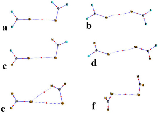
Figure 5.
AIM diagrams of homodimers of R1R2C=Se. T2 structures in (a,c,e); T1 in (b,d,f). Bond critical points marked by small red circles along bond paths indicated by broken lines.
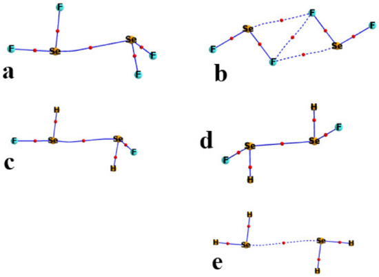
Figure 6.
AIM diagrams of homodimers of R1R2Se. T2 structures in (a,c); T1 in (b,d,e). Bond critical points marked by small red circles along bond paths indicated by broken lines.
A quantitative measure of noncovalent bond strength is the value of the electron density at its BCP. These quantities are listed in Table 4, including not only the Se··Se bonds but also those connected with a bond path in Figure 5 and Figure 6. For example, the purported CH··Se H-bond in Figure 5e has a ρBCP of 0.0065 au, which supplements the Y··Y value of 0.0074 au. The two FSe··F YBs in Figure 6b are quantified with densities of 0.0150 au, and supplemented by a F··F addition of 0.0129. The AIM diagrams of the S and Te analogs are similar, and their bond critical point densities are also supplied in Table 4. A comparison of these quantities with the interaction energies in Table 3 suggests a high degree of correlation between these quantities. The strong interactions in the F2Y and FHY homodimers are consistent with their large ρBCP. Additionally, the competing stabilities of the T1 and T2 geometries generally extend to the AIM densities. It should be noted that the bonding interactions in the F2Y dimers should not be characterized as Y··Y chalcogen bonds, but rather as a pair of Y··F, supplemented by a single F··F.
Table 4.
AIM bond critical point density, ρBCP (10−4 au), for homodimers.
Another means to identify the nature of each noncovalent bond, along with some measure of its strength, arises through NBO analysis, which pinpoints the source and sink of density shifts between the two molecules. For example, the majority of the YBs observed here show up in the NBO analysis in terms of second-order perturbation energy for a transfer from the Y lone pair of one molecule to the σ*(YR) antibonding orbital of the other, where R refers to the atom lying approximately opposite to the electron donor Y atom. These quantities are contained in Table 5, with several exceptions footnoted. Given the symmetric nature of the T1 structures, the values listed in Table 5 could perhaps be doubled as a measure of the YB bond strength, since there are equal transfers occurring in each direction.
Table 5.
NBO value of E2 (kcal/mol) for Ylp→σ*(YR) where R refers to the H or F atom lying opposite the Ylp.
The NBO data were largely consistent with AIM in terms of the type and strength of bonding present, with some exceptions. For example, the Y··F bond path indicated by AIM for the SCF2 T2 dimer was not supported by NBO. The two approaches agreed on the presence of FY··F chalcogen bonds in the YF2 T1 dimers, but NBO denied the existence of the direct F··F contact predicted by AIM. Indeed, an earlier study [73] suggested that F··F interactions of this sort that are denoted by AIM bond paths can signify a repulsive rather than an attractive interaction. Another point of dispute arises for the CH··Y H-bonds that AIM places in the YCH2 T2 dimers, but which are unconfirmed by NBO.
Another window into the sort of bonding that is present is associated with electron density redistributions. Figure 7 displays these density shifts as the difference between the density of the dimer and the sum of densities of the two individual monomers, with the nuclei in the same positions. Density increases arising from the interaction are indicated by the purple regions, while green designates density loss. Figure 7a,c represent the shifts within the T2 complexes of SeCF2 and SeF2, respectively. Both diagrams contain the elements of a classic YB, where there is a purple region of density accumulation between the two Y atoms, and a green loss immediately to the right of the electron acceptor atom. The T1 structure of SeCF2 in Figure 7b is consistent with the idea of a YB where each Se atom acts simultaneously as both electron donor and acceptor, with appropriate alternating green and purple areas. Both AIM and NBO suggested that it was the F atom that served as electron donor in the two FSe··F YBs in the T1 structure of SeF2. This same concept is further reinforced in the density shift pattern in Figure 7d by the purple regions enveloping the relevant F atoms. Another point of agreement in this complex is the absence of direct Se··Se contact, as there was only a green density depletion region along the axis between these two atoms. As a parenthetical note, due to the much stronger interactions in the SeF2 dimer, the contours depicted in Figure 7c,d represent changes of ±0.001 au, as compared to ±0.0002 au for the SeCF2 dimers with their much weaker bonding.
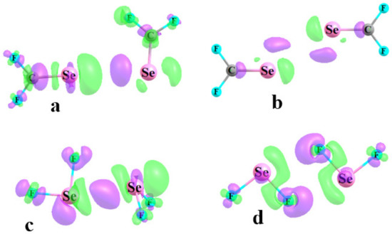
Figure 7.
Electron density difference diagrams of F2C=Se, and (b), and F2Se, (b,d). Purple and green regions designate density gain and loss, respectively. Contours shown in (a,b) are ±0.0002 au, and ±0.001 au in (c,d).
There is also a geometric consequence of the interaction between the two monomers. The charge transferred into the σ*(CY) antibonding orbital has a tendency to elongate this bond. This stretching was indeed observed, as can be seen from the changes in this bondlength within the electron acceptor of the T2 structure listed in the first column of each section of Table 6. In concert with the strengthening bond as the Y atom grew larger, so too did the elongation in the S < Se < Te sequence. Additionally, consistent with the E2 quantities in Table 5, there was a much higher degree of bond stretching in the R1R2Y systems than in their R1R2CY analogues. The replacement of F atoms by H conformed to the same patterns as in the E2 values. The changes in the electron donor molecules differed, depending upon whether the Y atom was engaged in a double bond to C or to a pair of substituents, as in R1R2Y. In the former case, the C=Y bond tended to stretch, while a contraction was observed in the latter. Within the context of the T1 geometries where both molecules serve simultaneously as both donor and acceptor, there was an overall stretch of the two bonds, with the exception of the YH bonds for YH2.
Table 6.
Change in internal bondlength to Y of monomers (Å) caused by formation of homodimer. ED and EA refer to electron donor and acceptor unit, respectively.
4. Discussion
A comparison of the minima on the surfaces of the chalcogen-bonded dimers here, and the previously studied halogen bonded analogues, reveals both similarities and differences. For the FX··XF dimers, the T2 geometries represented minima on the surface, whereas the symmetric T1 structures did not. Each of the latter instead comprised a transition state, separating one T2 geometry from its equivalent counterpart where the role of electron donor and acceptor were reversed. As such, the T2 structures are universally lower in energy than T1, although this energy difference is not necessarily very large.
The situation for the YB systems is more nuanced. Some T2 geometries are true minima, as for example TeCF2 and SeF2, whereas a number of others require a geometric restriction such as enforced FY··Y linearity. Unlike the FX dimers, some of the T1 geometries are true minima for the Y-bonded systems; others occur only if the symmetry is enforced by equal RY··Y angles. This restriction seems to be necessary only for the molecules with a poorly developed σ-hole, such as YH2 or YCH2.
One point of similarity between the XB and YB dimers lies in the greater stability of the T2 geometry as compared to T1, for the doubly bonded R1R2C=Y complexes. In most cases, this energy difference was a small one, considerably less than 1 kcal/mol. However, this situation reversed itself for the FX dimers, in that it was the symmetric T1 geometries that were more stable for the smaller R1R2Y homodimers. These singly bonded cases had stronger bonding overall, in addition to a large difference between T1 and T2. On the other hand, this exaggerated stability of the YF2 T1 homodimers must be considered in the light of the actual bonding pattern. These complexes forgo the Y··Y chalcogen bonds of the majority of the other structures considered here, in favor of a pair of Y··F interactions that take advantage of the negative MEP associated with the very electronegative F atom. They are perhaps supplemented by an AIM bond path between the same two F atoms, although this particular interaction is absent in NBO analysis.
As the Y atom grew larger, and more polarizable and electropositive, it is natural that its σ-hole deepened, as was indeed found to be the case. At the same time, one would expect that the MEP of the Y lone pair should change in the opposite direction, becoming less negative. If such were the case, then these two effects might counteract one another, and the Y··Y chalcogen bond strength ought not change much. However, it was found that the transition from S to Se to Te had very little effect upon the MEP of the Y lone pair. It was therefore the σ-hole depth that dominated the trend, causing the YB strength to increase with larger Y.
Conversely, one can consider the trends in MEP maximum and minimum as the F atoms were replaced by H. Taking the R1R2CY case first, each such replacement removed one electron-withdrawing substituent, thereby weakening the positive σ-hole. This same substitution allowed the lone pair MEP minimum to become more negative, so there was a certain degree of cancellation between these two trends. It is for this reason that the interaction energies of these R1R2CY homodimers were only mildly sensitive to these F→H replacements.
The patterns in the MEP extrema are a bit more complicated for the R1R2Y units. There was, indeed, a substantially more negative Y lone pair MEP minimum as each F changed to H. However, the first such substitution from YF2 to YFH had very little effect on the Y σ-hole depth. This insensitivity was largely due to the proximity of the H atom of YFH to the σ-hole lying opposite the F. The positive MEP surrounding this H was able to partially blend in with this σ-hole (see Figure 2e), thereby magnifying what would otherwise be a shallower hole. Consequently, this morphing of YF2 to YFH changed the interaction energy by less than it would have otherwise. The low polarizability of the SH bond left the SH2 molecule without a formal σ-hole, and those of SeH2 and TeH2 were considerably smaller than in their fluorinated counterparts. Even if the Y atom of one YH2 was restricted to the HY axis extension of the other, the former rotated around so as to present its positive H atoms toward the negative lone pairs of the latter molecule, forsaking any possible Y··Y YB in favor of YH··Y H-bonds. In other words, the very diffuse positive region of one Y is incapable of successfully engaging with the negative Y lone pair of its partner.
It was noted above that Lewis acids with shallow, or even nonexistent, σ-holes such as the YCH2 units here are able to engage in a YB with a base, albeit one with a small interaction energy of less than 2 kcal/mol. This ability confirms an earlier work [74], where a similar finding extended to a range of other R1R2T=Y units where T referred to a general tetrel atom. It was further found there that these shallow energy minima could be deepened if the system was immersed in a solvent. Reservations have been expressed with an overemphasis on MEP extrema such as σ-holes as a means to analyze some noncovalent bonds, as for example a recent work [75] that stressed the importance of HOMO–LUMO interactions.
Chalcogen bonds between a pair of like Y atoms have also been examined in the context of thiophene, selenophene, and tellurophene homodimers [76] where the Y atom is embedded within a C4H4Y aromatic system. These optimized dimers closely resemble the symmetric T1 geometries and take on a similar bonding pattern, as introduced in Figure 3d. Interaction energies of 1.5–2.3 kcal/mol were computed, in the same range as those of the simpler nonaromatic R1R2T=Y systems studied here, where the Y atom was also sp2-hybridized; the AIM bond critical point densities were also quite similar.
Although sparser than the ample literature regarding YBs with electronegative atoms, such as O and N as electron donors, there is some prior evidence of bonds involving S, Se, and Te as both donor and acceptor [77,78,79,80,81]. A recent review [82] of such Y··Y interactions summarized a good deal of the literature up through 2018, and demonstrated that such YBs between divalent chalcogen atoms are not uncommon in the solid state and solution, and they can play an active role as intramolecular bonds in molecular conformation. Those involving Te tend to be the strongest.
Buralli et al. [83] examined (R1)2CSe··SeC(R2)2C complexes where R1 and R2 refer to various small substituents. The calculations restricted these systems to a fully linear CSe··SeC arrangement, and arrived at interaction energies between 1 and 2 kcal/mol, although these structures were not true minima. S··S YBs occurred in a secondary minimum structure when dimethyl sulfide combined with 2,2,3,4-tetrafluoro-1,3-dithietane, with both S atoms in sp3 hybridization [84] in solution. The authors surmised that this S··S interaction was no weaker than that between S and O.
Recent quantum calculations [85] considered Y=C=Y units in geometries akin to the T1 and T2 structures described above. Computed interaction energies were in the same range as noted above for R1R2C=Y homodimers, and in another point of agreement the T1 and T2 stabilities were quite similar for these two geometry types. A search of the CSD carried out by these authors identified a number that they classified as T1, but T2 was less prevalent, despite its lower energy in their quantum calculations. Arrangements akin to T1 were observed in crystals and studied by model Te(CH2)m oligomers [86] in tubular packing. An earlier survey of the CSD [87] considered the C=S···S=C motif involving exclusively sulfur and identified quite a number of T1 sorts of geometric dispositions. Their quantum calculations found true T1 minima for X2CS dimers for X=NH2, OH, and F, but not for H and Cl. Their computed binding energies for (H2CS)2 and (F2CS)2 closely match the data reported here for these homodimers.
Other studies of Y··Y interactions focused on the triangular variety involving three Y atoms in a roughly equilateral triangle arrangement, which occurs on occasion within the CSD [88,89,90]. Calculations confirmed the strengthening effect of enlarging the three Y atoms.
5. Conclusions
Homodimers comprising either R1R2C=Y where Y takes on sp2 hybridization, or the R1R2Y unit with sp3 hybridization, can assume both T1 and T2 structures, although these geometries do not represent true minima on their potential energy surface in all cases. T2 contains a classic YB which links the σ-hole of one Y atom with a lone pair of the other, whereas the Y··Y bonding in the more symmetrical T1 contains a pair of such linkages wherein each Y serves as electron donor in one interaction and acceptor in the other. The interaction energies are considerably larger for the R1R2Y systems than for R1R2C=Y, due in large measure to much deeper σ-holes in the former monomers. However, H2Y units without the benefit of an electron-withdrawing substituent are unable to form stable T2 homodimers, and T1 is only possible with a geometrical restriction. Whether T1 or T2, the YB energy rises along with the size of the Y atom, reaching as high as 14.3 kcal/mol for the T1 structure of TeF2. The classic YB of T2 is favored over T1 for R1R2C=Y, although only by a small margin, but the opposite is true for the smaller R1R2Y. All of the homodimers are bound via RY··Y chalcogen bonds, with the single exception of the T1 geometries of YF2, where an F atom replaces Y as the electron donor in a pair of FY··F bonds.
Funding
This research was funded by NSF Grant No. 1954310.
Data Availability Statement
All data are available upon request to the author.
Acknowledgments
This material is based upon work supported by the National Science Foundation under Grant No. 1954310.
Conflicts of Interest
The author declares no conflict of interest.
References
- Pimentel, G.C.; McClellan, A.L. The Hydrogen Bond; Freeman: San Francisco, CA, USA, 1960. [Google Scholar]
- Schuster, P. Hydrogen Bonds; Springer: Berlin/Heidelberg, Germany, 1984; Volume 120, p. 117. [Google Scholar]
- Latajka, Z.; Scheiner, S. Effects of basis set and electron correlation on the calculated properties of the ammonia dimer. J. Chem. Phys. 1984, 81, 407–409. [Google Scholar] [CrossRef]
- Joesten, M.D.; Schaad, L.J. Hydrogen Bonding; Marcel Dekker: New York, NY, USA, 1974; p. 622. [Google Scholar]
- Cybulski, S.; Scheiner, S. Hydrogen bonding and proton transfers involving triply bonded atoms. HC≡N and HC≡CH. J. Am. Chem. Soc. 1987, 109, 4199–4206. [Google Scholar] [CrossRef]
- Desiraju, G.R.; Steiner, T. The Weak Hydrogen Bond in Structural Chemistry and Biology; Oxford University Press: New York, NY, USA, 1999; p. 507. [Google Scholar]
- Szczesniak, M.M.; Scheiner, S. Møller-Plesset treatment of electron correlation in (HOHOH)−. J. Chem. Phys. 1982, 77, 4586–4593. [Google Scholar] [CrossRef]
- Jeffrey, G.A.; Saenger, W. Hydrogen Bonding in Biological Structures; Springer: Berlin/Heidelberg, Germany, 1991. [Google Scholar]
- Scheiner, S. Hydrogen Bonding: A Theoretical Perspective; Oxford University Press: New York, NY, USA, 1997; p. 375. [Google Scholar]
- Gilli, G.; Gilli, P. The Nature of the Hydrogen Bond; Oxford University Press: Oxford, UK, 2009; p. 313. [Google Scholar]
- Horowitz, S.; Dirk, L.M.A.; Yesselman, J.D.; Nimtz, J.S.; Adhikari, U.; Mehl, R.A.; Scheiner, S.; Houtz, R.L.; Al-Hashimi, H.M.; Trievel, R.C. Conservation and Functional Importance of Carbon-Oxygen Hydrogen Bonding in AdoMet-dependent Methyltransferases. J. Am. Chem. Soc. 2013, 135, 15536–15548. [Google Scholar] [CrossRef]
- Mertsalov, D.F.; Gomila, R.M.; Zaytsev, V.P.; Grigoriev, M.S.; Nikitina, E.V.; Zubkov, F.I.; Frontera, A. On the Importance of Halogen Bonding Interactions in Two X-ray Structures Containing All Four (F, Cl, Br, I) Halogen Atoms. Crystals 2021, 11, 1406. [Google Scholar] [CrossRef]
- Del Bene, J.E.; Alkorta, I.; Elguero, J. Probing the structures, binding energies, and spin-spin coupling constants of halogen-bonded Azine:ClF complexes. Chem. Phys. Lett. 2020, 761, 137916. [Google Scholar] [CrossRef]
- Scheiner, S.; Lu, J. Halogen, Chalcogen, and Pnicogen Bonding Involving Hypervalent Atoms. Chem. Eur. J. 2018, 24, 8167–8177. [Google Scholar] [CrossRef]
- Palusiak, M.; Grabowski, S.J. Do intramolecular halogen bonds exist? Ab initio calculations and crystal structures’ evidences. Struct. Chem. 2008, 19, 5–11. [Google Scholar] [CrossRef]
- Grabowski, S.J. Halogen bond and its counterparts: Bent’s rule explains the formation of nonbonding interactions. J. Phys. Chem. A 2011, 115, 12340–12347. [Google Scholar] [CrossRef]
- Scheiner, S.; Hunter, S. Influence of Substituents in the Benzene Ring on the Halogen Bond of Iodobenzene with Ammonia. ChemPhysChem 2022, 23, e202200011. [Google Scholar] [CrossRef]
- Murray, J.S.; Politzer, P. Can Counter-Intuitive Halogen Bonding Be Coulombic? ChemPhysChem 2021, 22, 1201–1207. [Google Scholar] [CrossRef] [PubMed]
- Cunha, A.V.; Havenith, R.W.A.; van Gog, J.; De Vleeschouwer, F.; De Proft, F.; Herrebout, W. The Halogen Bond in Weakly Bonded Complexes and the Consequences for Aromaticity and Spin-Orbit Coupling. Molecules 2023, 28, 772. [Google Scholar] [CrossRef] [PubMed]
- Bauzá, A.; Frontera, A. Competition between lone pair-π, halogen-π and triel bonding interactions involving BX3 (X = F, Cl, Br and I) compounds: An ab initio study. Theor. Chem. Acc. 2017, 136, 37. [Google Scholar] [CrossRef]
- Cavallo, G.; Metrangolo, P.; Milani, R.; Pilati, T.; Priimagi, A.; Resnati, G.; Terraneo, G. The Halogen Bond. Chem. Rev. 2016, 116, 2478–2601. [Google Scholar] [CrossRef] [PubMed]
- Scheiner, S. Sensitivity of Noncovalent Bonds to Intermolecular Separation: Hydrogen, Halogen, Chalcogen, and Pnicogen Bonds. CrystEngComm 2013, 15, 3119–3124. [Google Scholar] [CrossRef]
- Clark, T.; Hennemann, M.; Murray, J.S.; Politzer, P. Halogen bonding: The s-hole. J. Mol. Model. 2007, 13, 291–296. [Google Scholar] [CrossRef]
- Vincent de Paul, N.N.; Scheiner, S. Comparison of p-hole tetrel bonding with s-hole halogen bonds in complexes of XCN (X = F, Cl, Br, I) and NH3. Phys. Chem. Chem. Phys. 2016, 18, 3581–3590. [Google Scholar]
- Taylor, A.J.; Docker, A.; Beer, P.D. Allosteric and Electrostatic Cooperativity in a Heteroditopic Halogen Bonding Receptor System. Chem.–Asian J. 2023, 18, e202201170. [Google Scholar] [CrossRef]
- Nyburg, S.C.; Wong-Ng, W. Potential energy interactions in solid dichlorine. Inorg. Chem. 1979, 18, 2790–2791. [Google Scholar] [CrossRef]
- Price, S.L.; Stone, A.J.; Lucas, J.; Rowland, R.S.; Thornley, A.E. The nature of -Cl⋯Cl- intermolecular interactions. J. Am. Chem. Soc. 1994, 116, 4910–4918. [Google Scholar] [CrossRef]
- Brammer, L.; Mínguez Espallargas, G.; Libri, S. Combining metals with halogen bonds. CrystEngComm 2008, 10, 1712–1727. [Google Scholar] [CrossRef]
- Bui, T.T.T.; Dahaoui, S.; Lecomte, C.; Desiraju, G.R.; Espinosa, E. The Nature of Halogen⋯Halogen Interactions: A Model Derived from Experimental Charge-Density Analysis. Angew. Chem. Int. Ed. 2009, 48, 3838–3841. [Google Scholar] [CrossRef] [PubMed]
- Desiraju, G.R.; Parthasarathy, R. The nature of halogen…halogen interactions: Are short halogen contacts due to specific attractive forces or due to close packing of nonspherical atoms? J. Am. Chem. Soc. 1989, 111, 8725–8726. [Google Scholar] [CrossRef]
- Pedireddi, V.R.; Reddy, D.S.; Goud, B.S.; Craig, D.C.; Rae, A.D.; Desiraju, G.R. The nature of halogen ⋯ halogen interactions and the crystal structure of 1,3,5,7-tetraiodoadamantane. J. Chem. Soc. Perkin Trans. 2 1994, 11, 2353–2360. [Google Scholar] [CrossRef]
- Fourmigué, M. Halogen bonding: Recent advances. Curr. Opin. Solid State Mater. Sci. 2009, 13, 36–45. [Google Scholar] [CrossRef]
- Mukherjee, A.; Tothadi, S.; Desiraju, G.R. Halogen Bonds in Crystal Engineering: Like Hydrogen Bonds yet Different. Acc. Chem. Res. 2014, 47, 2514–2524. [Google Scholar] [CrossRef]
- Stone, A.J.; Price, S.L. Some new ideas in the theory of intermolecular forces: Anisotropic atom-atom potentials. J. Phys. Chem. 1988, 92, 3325–3335. [Google Scholar] [CrossRef]
- Spilfogel, T.S.; Titi, H.M.; Friščić, T. Database Investigation of Halogen Bonding and Halogen⋯Halogen Interactions between Porphyrins: Emergence of Robust Supramolecular Motifs and Frameworks. Cryst. Growth Des. 2021, 21, 1810–1832. [Google Scholar] [CrossRef]
- Nyburg, S.C.; Faerman, C.H. A revision of van der Waals atomic radii for molecular crystals: N, O, F, S, Cl, Se, Br and I bonded to carbon. Acta Crystallogr. B 1985, 41, 274–279. [Google Scholar] [CrossRef]
- Aliyarova, I.S.; Ivanov, D.M.; Soldatova, N.S.; Novikov, A.S.; Postnikov, P.S.; Yusubov, M.S.; Kukushkin, V.Y. Bifurcated Halogen Bonding Involving Diaryliodonium Cations as Iodine(III)-Based Double-σ-Hole Donors. Cryst. Growth Des. 2021, 21, 1136–1147. [Google Scholar] [CrossRef]
- Adonin, S.A.; Bondarenko, M.A.; Novikov, A.S.; Sokolov, M.N. Halogen Bonding in Isostructural Co(II) Complexes with 2-Halopyridines. Crystals 2020, 10, 289. [Google Scholar] [CrossRef]
- Adonin, S.A.; Gorokh, I.D.; Abramov, P.A.; Novikov, A.S.; Korolkov, I.V.; Sokolov, M.N.; Fedin, V.P. Chlorobismuthates Trapping Dibromine: Formation of Two-Dimensional Supramolecular Polyhalide Networks with Br2 Linkers. Eur. J. Inorg. Chem. 2017, 2017, 4925–4929. [Google Scholar] [CrossRef]
- Scheiner, S. Characterization of Type I and II Interactions between Halogen Atoms. Cryst. Growth Des. 2022, 22, 2692–2702. [Google Scholar] [CrossRef]
- Desiraju, G.R.; Nalini, V. Database analysis of crystal-structure-determining interactions involving sulphur: Implications for the design of organic metals. J. Mater. Chem. 1991, 1, 201–203. [Google Scholar] [CrossRef]
- Iwaoka, M.; Tomoda, S. A Model Study on the Effect of an Amino Group on the Antioxidant Activity of Glutathione Peroxidase. J. Am. Chem. Soc. 1994, 116, 2557–2561. [Google Scholar] [CrossRef]
- Minyaev, R.M.; Minkin, V.I. Theoretical study of O - > X (S, Se, Te) coordination in organic compounds. Can. J. Chem. 1998, 76, 776–788. [Google Scholar] [CrossRef]
- Carugo, O. Stereochemistry of the interaction between methionine sulfur and the protein core. Biol. Chem. 1999, 380, 495–498. [Google Scholar] [CrossRef]
- Fick, R.J.; Kroner, G.M.; Nepal, B.; Magnani, R.; Horowitz, S.; Houtz, R.L.; Scheiner, S.; Trievel, R.C. Sulfur–Oxygen Chalcogen Bonding Mediates AdoMet Recognition in the Lysine Methyltransferase SET7/9. ACS Chem. Biol. 2016, 11, 748–754. [Google Scholar] [CrossRef]
- Mukherjee, A.J.; Zade, S.S.; Singh, H.B.; Sunoj, R.B. Organoselenium Chemistry: Role of Intramolecular Interactions. Chem. Rev. 2010, 110, 4357–4416. [Google Scholar] [CrossRef]
- Aakeroy, C.B.; Bryce, D.L.; Desiraju, G.R.; Frontera, A.; Legon Anthony, C.; Nicotra, F.; Rissanen, K.; Scheiner, S.; Terraneo, G.; Metrangolo, P.; et al. Definition of the chalcogen bond (IUPAC Recommendations 2019). Pure Appl. Chem. 2019, 91, 1889. [Google Scholar] [CrossRef]
- Fanfrlík, J.; Přáda, A.; Padělková, Z.; Pecina, A.; Macháček, J.; Lepšík, M.; Holub, J.; Růžička, A.; Hnyk, D.; Hobza, P. The Dominant Role of Chalcogen Bonding in the Crystal Packing of 2D/3D Aromatics. Angew. Chem. Int. Ed. 2014, 53, 10139–10142. [Google Scholar] [CrossRef] [PubMed]
- Legon, A.C. Tetrel, pnictogen and chalcogen bonds identified in the gas phase before they had names: A systematic look at non-covalent interactions. Phys. Chem. Chem. Phys. 2017, 19, 14884–14896. [Google Scholar] [CrossRef] [PubMed]
- Alkorta, I.; Elguero, J.; Del Bene, J.E. Complexes of O=C=S with Nitrogen Bases: Chalcogen Bonds, Tetrel Bonds, and Other Secondary Interactions. ChemPhysChem 2018, 19, 1886–1894. [Google Scholar] [CrossRef] [PubMed]
- Trujillo, C.; Rozas, I.; Elguero, J.; Alkorta, I.; Sánchez-Sanz, G. Modulating intramolecular chalcogen bonds in aromatic (thio)(seleno)phene-based derivatives. Phys. Chem. Chem. Phys. 2019, 21, 23645–23650. [Google Scholar] [CrossRef]
- Carugo, O.; Resnati, G.; Metrangolo, P. Chalcogen Bonds Involving Selenium in Protein Structures. ACS Chem. Biol. 2021, 16, 1622–1627. [Google Scholar] [CrossRef]
- Scheiner, S. Participation of S and Se in hydrogen and chalcogen bonds. CrystEngComm 2021, 23, 6821–6837. [Google Scholar] [CrossRef]
- Biswal, H.S.; Sahu, A.K.; Galmés, B.; Frontera, A.; Chopra, D. Se⋯O/S and S⋯O Chalcogen Bonds in Small Molecules and Proteins: A Combined CSD and PDB Study. ChemBioChem 2022, 23, e202100498. [Google Scholar] [CrossRef]
- Mahmudov, K.T.; Gurbanov, A.V.; Aliyeva, V.A.; Guedes da Silva, M.F.C.; Resnati, G.; Pombeiro, A.J.L. Chalcogen bonding in coordination chemistry. Coord. Chem. Rev. 2022, 464, 214556. [Google Scholar] [CrossRef]
- Fedorova, I.I.; Soldatova, N.S.; Ivanov, D.M.; Nikiforova, K.; Aliyarova, I.S.; Yusubov, M.S.; Tolstoy, P.M.; Gomila, R.M.; Frontera, A.; Kukushkin, V.Y.; et al. Benzothienoiodolium Cations Doubly Bonded to Anions via Halogen–Chalcogen and Halogen–Hydrogen Supramolecular Synthons. Cryst. Growth Des. 2023, 23, 2661–2674. [Google Scholar] [CrossRef]
- Hein, R.; Beer, P.D. Halogen bonding and chalcogen bonding mediated sensing. Chem. Sci. 2022, 13, 7098–7125. [Google Scholar] [CrossRef]
- Zhao, Y.; Truhlar, D.G. The M06 suite of density functionals for main group thermochemistry, thermochemical kinetics, noncovalent interactions, excited states, and transition elements: Two new functionals and systematic testing of four M06-class functionals and 12 other functionals. Theor. Chem. Acc. 2008, 120, 215–241. [Google Scholar]
- Karthikeyan, S.; Ramanathan, V.; Mishra, B.K. Influence of the substituents on the CH⋯p interaction: Benzene–methane complex. J. Phys. Chem. A 2013, 117, 6687–6694. [Google Scholar] [CrossRef] [PubMed]
- Kříž, K.; Řezáč, J. Non-covalent interactions atlas benchmark data sets 4: σ-hole interactions. Phys. Chem. Chem. Phys. 2022, 24, 14794–14804. [Google Scholar] [CrossRef] [PubMed]
- Boese, A.D. Density Functional Theory and Hydrogen Bonds: Are We There Yet? ChemPhysChem 2015, 16, 978–985. [Google Scholar] [CrossRef]
- Kozuch, S.; Martin, J.M.L. Halogen bonds: Benchmarks and theoretical analysis. J. Chem. Theory Comput. 2013, 9, 1918–1931. [Google Scholar] [CrossRef]
- Walker, M.; Harvey, A.J.A.; Sen, A.; Dessent, C.E.H. Performance of M06, M06-2X, and M06-HF Density Functionals for Conformationally Flexible Anionic Clusters: M06 Functionals Perform Better than B3LYP for a Model System with Dispersion and Ionic Hydrogen-Bonding Interactions. J. Phys. Chem. A 2013, 117, 12590–12600. [Google Scholar] [CrossRef]
- Thanthiriwatte, K.S.; Hohenstein, E.G.; Burns, L.A.; Sherrill, C.D. Assessment of the performance of DFT and DFT-D methods for describing distance dependence of hydrogen-bonded interactions. J. Chem. Theory Comput. 2011, 7, 88–96. [Google Scholar] [CrossRef]
- Podeszwa, R.; Szalewicz, K. Density functional theory overcomes the failure of predicting intermolecular interaction energies. J. Chem. Phys. 2012, 136, 161102. [Google Scholar] [CrossRef]
- Liao, M.S.; Lu, Y.; Scheiner, S. Performance assessment of density-functional methods for study of charge-transfer complexes. J. Comput. Chem. 2003, 24, 623–631. [Google Scholar] [CrossRef]
- Frisch, M.J.; Trucks, G.W.; Schlegel, H.B.; Scuseria, G.E.; Robb, M.A.; Cheeseman, J.R.; Scalmani, G.; Barone, V.; Petersson, G.A.; Nakatsuji, H.; et al. Gaussian 16, Rev. C.01; Gaussian, Inc.: Wallingford, CT, USA, 2016.
- Boys, S.F.; Bernardi, F. The calculation of small molecular interactions by the differences of separate total energies. Some procedures with reduced errors. Mol. Phys. 1970, 19, 553–566. [Google Scholar] [CrossRef]
- Lu, T.; Chen, F. Multiwfn: A multifunctional wavefunction analyzer. J. Comput. Chem. 2012, 33, 580–592. [Google Scholar] [CrossRef] [PubMed]
- Keith, T.A. AIMAll, TK Gristmill Software: Overland Park, KS, USA, 2013.
- Reed, A.E.; Weinhold, F.; Curtiss, L.A.; Pochatko, D.J. Natural bond orbital analysis of molecular interactions: Theoretical studies of binary complexes of HF, H2O, NH3, N2, O2, F2, CO and CO2 with HF, H2O, and NH3. J. Chem. Phys. 1986, 84, 5687–5705. [Google Scholar] [CrossRef]
- Reed, A.E.; Curtiss, L.A.; Weinhold, F. Intermolecular interactions from a natural bond orbital, donor-acceptor viewpoint. Chem. Rev. 1988, 88, 899–926. [Google Scholar] [CrossRef]
- Forni, A.; Franchini, D.; Dapiaggi, F.; Pieraccini, S.; Sironi, M.; Scilabra, P.; Pilati, T.; Petko, K.I.; Resnati, G.; Yagupolkii, Y.L. Featuring I⋯N Halogen Bond and Weaker Interactions in Iodoperfluoroalkylimidazoles: An Experimental and Theoretical Charge Density Study. Cryst. Growth Des. 2019, 19, 1621–1631. [Google Scholar] [CrossRef]
- Wysokiński, R.; Zierkiewicz, W.; Michalczyk, M.; Scheiner, S. Ability of Lewis Acids with Shallow σ-Holes to Engage in Chalcogen Bonds in Different Environments. Molecules 2021, 26, 6394. [Google Scholar] [CrossRef]
- De Azevedo Santos, L.; Ramalho, T.C.; Hamlin, T.A.; Bickelhaupt, F.M. Intermolecular Covalent Interactions: Nature and Directionality. Chem. Eur. J. 2023, 29, e202203791. [Google Scholar] [CrossRef]
- Scheiner, S. Various Sorts of Chalcogen Bonds Formed by an Aromatic System. J. Phys. Chem. A 2022, 126, 4025–4035. [Google Scholar] [CrossRef]
- Knight, F.R.; Fuller, A.L.; Bühl, M.; Slawin, A.M.Z.; Woollins, J.D. Synthetic and structural studies of 1,8-chalcogen naphthalene derivatives. Chem. Eur. J. 2010, 16, 7503–7516. [Google Scholar] [CrossRef]
- Sánchez-Sanz, G.; Alkorta, I.; Elguero, J. A theoretical study of the conformation of 2,2′-bifuran, 2,2′-bithiophene, 2,2′-bitellurophene and mixed derivatives: Chalcogen–chalcogen interactions or dipole–dipole effects? Comput. Theor. Chem. 2011, 974, 37–42. [Google Scholar] [CrossRef]
- Esrafili, M.D.; Mohammadian-Sabet, F. Homonuclear chalcogen–chalcogen bond interactions in complexes pairing YO3 and YHX molecules (Y = S, Se; X = H, Cl, Br, CCH, NC, OH, OCH3): Influence of substitution and cooperativity. Int. J. Quantum Chem. 2016, 116, 529–536. [Google Scholar] [CrossRef]
- Si, M.K.; Lo, R.; Ganguly, B. The origin and magnitude of intramolecular quasi-cyclic S⋯O and S⋯S interactions revisited: A computational study. Chem. Phys. Lett. 2015, 631–632, 6–11. [Google Scholar] [CrossRef]
- Flores-Huerta, A.G.; Tkatchenko, A.; Galván, M. Nature of Hydrogen Bonds and S⋯S Interactions in the l-Cystine Crystal. J. Phys. Chem. A 2016, 120, 4223–4230. [Google Scholar] [CrossRef] [PubMed]
- Gleiter, R.; Haberhauer, G.; Werz, D.B.; Rominger, F.; Bleiholder, C. From Noncovalent Chalcogen–Chalcogen Interactions to Supramolecular Aggregates: Experiments and Calculations. Chem. Rev. 2018, 118, 2010–2041. [Google Scholar] [CrossRef] [PubMed]
- Buralli, G.J.; Duarte, D.J.R.; Peruchena, N.M.; Alkorta, I. Simultaneous Occurrence of Quadruple Lewis Acid–Base Interactions between Selenium Atoms in Selenocarbonyl Dimers. ChemPhysChem 2017, 18, 3498–3503. [Google Scholar] [CrossRef]
- Geboes, Y.; De Vos, E.; Herrebout, W.A. S⋯S and S⋯P chalcogen bonding in solution: A cryospectroscopic study of the complexes of 2,2,4,4-tetrafluoro-1,3-dithietane with dimethyl sulfide and trimethylphosphine. New J. Chem. 2018, 42, 10563–10571. [Google Scholar] [CrossRef]
- Ibrahim, M.A.A.; Shehata, M.N.I.; Soliman, M.E.S.; Moustafa, M.F.; El-Mageed, H.R.A.; Moussa, N.A.M. Unusual chalcogen⋯chalcogen interactions in like⋯like and unlike Y=C=Y⋯Y=C=Y complexes (Y = O, S, and Se). Phys. Chem. Chem. Phys. 2022, 24, 3386–3399. [Google Scholar] [CrossRef]
- Rodewald, M.; Rautiainen, J.M.; Niksch, T.; Görls, H.; Oilunkaniemi, R.; Weigand, W.; Laitinen, R.S. Chalcogen-Bonding Interactions in Telluroether Heterocycles [Te(CH2)m]n (n = 1–4; m = 3–7). Chem. Eur. J. 2020, 26, 13806–13818. [Google Scholar] [CrossRef]
- Shukla, R.; Chopra, D. Crystallographic and Theoretical Investigation on the Nature and Characteristics of Type I C=S⋯S=C Interactions. Cryst. Growth Des. 2016, 16, 6734–6742. [Google Scholar] [CrossRef]
- Wang, R.; Lu, Y.; Xu, Z.; Liu, H. Triangular Interchalcogen Interactions: A Joint Crystallographic Data Analysis and Theoretical Study. J. Phys. Chem. A 2021, 125, 4173–4183. [Google Scholar] [CrossRef]
- Mo, L.; Zeng, Y.; Li, X.; Meng, L. The enhancing effects of molecule X (X = PH2Cl, SHCl, ClCl) on chalcogen–chalcogen interactions in cyclic trimers Y⋯Y⋯X (Y = SHCl, SeHCl). Int. J. Quantum Chem. 2017, 117, e25354. [Google Scholar] [CrossRef]
- Esrafili, M.D.; Mohammadian-Sabet, F. An ab initio study on chalcogen–chalcogen bond interactions in cyclic (SHX)3 complexes (X = F, Cl, CN, NC, CCH, OH, OCH3, NH2). Chem. Phys. Lett. 2015, 628, 71–75. [Google Scholar] [CrossRef]


Disclaimer/Publisher’s Note: The statements, opinions and data contained in all publications are solely those of the individual author(s) and contributor(s) and not of MDPI and/or the editor(s). MDPI and/or the editor(s) disclaim responsibility for any injury to people or property resulting from any ideas, methods, instructions or products referred to in the content. |
© 2023 by the author. Licensee MDPI, Basel, Switzerland. This article is an open access article distributed under the terms and conditions of the Creative Commons Attribution (CC BY) license (https://creativecommons.org/licenses/by/4.0/).