Abstract
A (Fe, Cr)-free Co39.2Ni39.2Al21.6 eutectic medium-entropy alloy (EMEA) was designed and fabricated to study the microstructure and its evolution during slow solidification under different intensities of high static magnetic field (0 T, 5 T and 10 T). It was found that the original microstructure was characterized by FCC/BCC mixed herringbone eutectics consisting of two types of lamellar structures: a curved and wormy anomalous eutectic in the fringe, and a straight and long regular eutectic in the center. Nano-sized L10-type martensite layers are also distributed on the BCC lamellar as the martensitic transformation product. The FCC and BCC phases were enriched in Co and Al elements, respectively, while Ni element was distributed homogenously in both phases. With increasing magnetic field intensity, the herringbone eutectic structures remained stable, without the formation of a primary phase, while the phase constitution and the orientation relationships in the eutectic structures remained unchanged, with no obvious magnetically induced alignments. However, the lamellar spacing of the regular lamellar eutectic decreased significantly from 3.3 μm (0 T) to 1.93 μm (10 T); by contrast, the volume fraction of the anomalous eutectics increased considerably from 28.35% (0 T) to 55.14% (10 T), and the assumption that the imposed convection and destabilization of lamellar eutectics is controlled by the magnetic field is discussed in depth. Our results show a great potential for tailoring microstructures and properties by applying a strong magnetic field during the solidification process of EMEAs.
1. Introduction
In a departure from traditional metallurgical design philosophy, high-/medium-entropy alloys (HEAs/MEAs) are novel alloy systems with simple solid solution phases containing near-equimolar multicomponent elements [1,2] that exhibit tremendous potential for engineering applications and have attracted considerable attention due to their pronounced and intriguing characteristics [3,4,5,6,7]. Nevertheless, it remains a challenge to achieve the optimal combination of strength and ductility in single-phase HEAs/MEAs. That is, the FCC phases often exhibit excellent ductility but low strength, while BCC phases demonstrate improved strength at the cost of ductility. Additionally, the insufficient melt flowability and workability also hinder their use in actual applications. In order to overcome those shortcomings, the concept of eutectic high-/medium-entropy alloys (EHEAs/EMEAs), proposed by Lu et al., was developed, in which the characteristics of HEA/MEA and eutectic alloys are combined. EHEAs/EMEAs usually possess a fine lamellar FCC/BCC structure (in situ composite), with extraordinary castability, and are able to achieve a strength–ductility trade-off [8,9,10,11]. Such unique microstructures can be effectively tailored using various technologies such as heat treatment, rolling, additive manufacturing, sintering, etc., which are anticipated to allow the exploitation of their potential for further applications in a variety of fields. Singh et al. adopted the mechanical alloying and spark plasma sintering method to prepare an equiatomic Mg20Al20Si20Cr20Fe20 (at. %) low-density high-entropy alloy with high hardness and without the presence of the signature indentation cracks [12]. Rawat et al. proposed that choosing the laser wavelength and varying the physical parameters for its processing during the process of laser processing could be used to effectively obtain selective nano-precipitates on the surface of high-entropy alloy nanoparticles in order to adjust the physical properties [13].
Unfortunately, the relatively high energy consumption and low production efficiency of those techniques cannot be overlooked. Solidification, as an indispensable part during material processing, determines microstructure development through nucleation and crystal growth and manipulate the final properties of alloys. Controlling the solidification process, owing to its convenience and cost effectiveness for large-scale production, has been researched previously in the context of binary alloys and parts of ternary alloys like Co-B, Co-Sn alloys [14,15], whereas attention has seldom been paid towards (E)HEAs/(E)MEAs in the open literature, even though they are more common in practical application. For instance, Z. Chen et al. [16] found that the microstructures of Fe80C5Si10B5 alloy evolved from regular eutectic to anomalous eutectic structures with increasing undercooling, and then granular ferrite and borides occurred when the undercooling was higher, which is advantageous for enhanced wear-resistance performance. M. Rahul et al. [17] adopted the CALPHAD and an experimental approach to study the solidification of FeCoNiCuW0.5 alloy, and observed the liquid phase separation phenomenon. Nevertheless, regrettably, the solidification behaviors of multi-element EHEAs/EMEAs have scarcely been systematically considered, and their effects on properties are still ambiguous. Therefore, it is critical to clarify the mechanism of microstructure evolution and to further improve the properties of EHEAs/EMEAs. In recent years, strong magnetic fields (SMFs) have been widely applied in materials processing due to the non-contact transmission of energy and the diversity of magnetic effects, bringing about a phenomenon of greater abundance for the manipulation of the microstructures and properties of solidified alloys, including grain refinement [18], alignment and texture [19,20], columnar-to-equiaxed grain transition [21], segregation [22], etc. In this context, profound research on the solidification behavior and properties of EHEAs/EMEAs assisted by magnetic field should be systematically studied, and the mechanism of action of magnetic fields on microstructural solidification evolution should be illuminated in greater depth.
Co-Ni-Al alloy, as a common shape memory alloy, exhibits the microstructures typical of BCC austenite dendrites and FCC inter-dendritic precipitation. However, a trade-off between mechanical properties and magnetic properties is difficult to obtain [23,24]. In the present work, the design philosophy of EHEA/EMEA was applied to this system, and nominal Co39.2Ni39.2Al21.6 EMEAs with full lamellar microstructures were fabricated; subsequently, the microstructural solidification evolution and relative mechanical properties were investigated as a function of magnetic field intensity. This work could not only enrich our knowledge regarding magnetic-dependent microstructural evolution and property modification in the multi-component EHEA/EMEA Co-Ni-Al system, but could also provide guidance for controlling microstructures and properties under extreme conditions.
2. Materials and Methods
2.1. Alloy Preparation
In accordance with the binary eutectic phase diagram combined with the simple mixture method [25], EMEA with a composition of Co39.2Ni39.2Al21.6 was prepared by arc-melting a mixture of the constituent elements with purity higher than 99.99 wt.% under a Ti-gettered and high-purity argon atmosphere. The ingot was inverted and re-melted at least four times to ensure chemical homogeneity, and was then machined into several samples with an average mass of about 15 g. One of the samples (as-cast) was characterized using the SEM, XRD, EDS and EBSD techniques to analyze the phase constitution and microstructure of the master alloy, and the thermal behavior was also analyzed using differential scanning calorimeter (DSC) in an argon atmosphere from room temperature to 1500 °C with a heating/cooling rate of 10 K/min.
2.2. Solidification under Different Magnetic Field Intensities
The rest of the samples were ground and ultrasonically cleaned in order to remove impurities. Subsequently, each sample was encapsulated in a high-purity quartz tube that was evacuated to 10−3 Pa and filled with a bit of argon gas. Then, the tube was placed in the uniform heating region of a self-designed high-temperature resistance heating furnace, and inserted into the bore of the high-static-magnetic-field device. The static magnetic field could be stimulated in a tunable fashion within the range of 0 T to 10 T. More detailed information about the in situ heating system under magnetic field can be found in our previous work [26]. The furnace was heated to 1450 °C at a rate of 20 °C/min and held for 20 min, ensuring that each sample was fully melted and homogeneous. Then, the melt was cooled at a slower rate of 10 K/min to achieve near-equilibrium solidification without visible undercooling. Static magnetic fields of 0 T, 5 T, and 10 T were applied throughout the whole melting and solidification process.
2.3. Microstructure Characterization
The obtained samples were sectioned along the direction of the magnetic field and ground, polished and etched for microstructure observation. Phase constitutions were analyzed by XRD measurements (DX 2700, Dandong Haoyuan Instrument Co., Ltd, Dandong, China) using Co-Kα radiation. The morphologies were characterized using SEM and EBSD techniques performed using an FEI Quanta 650F(FEI Company, Hillsboro, OR, USA). The relative mechanical properties were determined on standard test samples (length = 6 mm, diameter = 3 mm) by performing compression tests at room temperature using a universal test machine (Instron 5982, Instron cooperation, Norwood, MA, USA) at a rate of 10−3 s−1.
The spacing of the eutectic flakes was evaluated by measuring the average distance between the flakes using the line intercept method [27]. Each spacing value was obtained on the basis of the average of ten individual measurements, where the average spacing λ is given by:
where M is the magnification of the microscopy, N0 is the number of flakes counted, and L is the length of the intercept line.
3. Results
3.1. Original Microstructure and Phase Constituents
Figure 1 shows the XRD pattern of the as-cast Co39.2Ni39.2Al21.6 EMEA, illustrating the dual-phase structure consisting of a BCC and FCC phase. The low-angle superlattice diffraction peaks at 2θ values of 44.02° and 44.94° correspond to the (111) plane of the FCC phase and the (110) plane of the BCC phase, respectively. Based on the position of the diffraction peaks, the lattice parameters of the FCC and BCC phases were estimated to be ~2.89 Å and 3.54 Å, respectively.
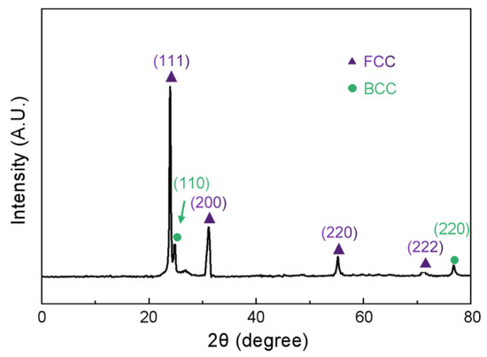
Figure 1.
XRD pattern of as-cast Co39.2Ni39.2Al21.6 EMEA. The side peak around 25° indicated by the green arrow is indexed as the (110) plane of BCC phase.
Figure 2 shows the SEM back-scattered electron images of the as-cast Co39.2Ni39.2Al21.6 EMEA at different magnifications. The as-cast alloy shows a typical lamellar morphology with an average inter-lamellar spacing of 1.3 μm (Figure 2a), and the absence of primary dendrite trunks with a larger size. The magnified BSE image in Figure 2b demonstrates the formation of two types of lamellar structure, i.e., the coupled alignment of lamellar structures composed of light phase and dark phase are uniformly distributed, presenting a long and flat lamellar morphology on the hundred micron scale, which are wrapped and embedded in another types of eutectics showing short and curved characteristics on the micron scale (marked by white arrows). The fraction of anomalous eutectic structures is estimated to be 11.7%. Similar microstructures to these have also been found in other EHEAs [10,28], where they are referred to as herringbone colonies, etc. It is thought that these unique structures are formed by the growth of the solid–liquid cellular interface, which is related to the anisotropy of interfacial energy and partial undercooling [29]. Zooming in further enabled us to detect large numbers of nano-sized lamellar structures precipitated in the dark lamellar structures (Figure 2c), which are considered to be the martensite phase transformed by the BCC-type austenite phase through a solid-state transition [30]. The SEM imaging results above confirm that a whole dual-phase eutectic of dual phases has been achieved, implying that the coupled eutectics were nucleated and grown cooperatively from undercooled liquid without the precipitation of lead phase. In order to verify this, the thermal behavior of the as-cast Co39.2Ni39.2Al21.6 EMEA was investigated using the DSC technique, and the results are presented in Figure 3. Only a single endothermic peak can be observed throughout the cooling process, and there is an absence of other peaks, confirming the eutectic composition of our system. In addition, the melting and nucleation temperatures (denoted as Tm and TE) are marked as 1390 °C and 1370 °C, respectively, indicating an extremely small degree of undercooling (ΔT = Tm − TE = 20 °C) when the cooling rate is 20 °C/min.
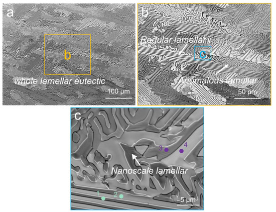
Figure 2.
SEM images of the as-cast Co39.2Ni39.2Al21.6 EMEA. (a) Low-magnification BSE image; (b) magnified BSE image in the solid orange box shown in (a); (c) high-magnification BSE image in the solid blue box shown in (b).
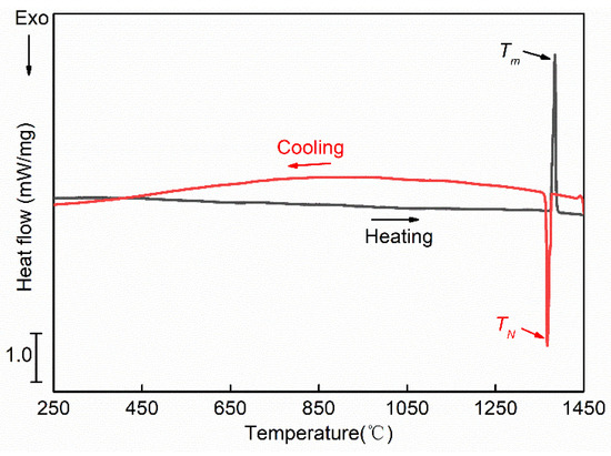
Figure 3.
DSC curve of the as-cast Co39.2Ni39.2Al21.6 EMEA.
The point-scanning EDS results obtained using the SEM technique are shown in Table 1. It can be observed that the dark BCC phase (Point 1) was enriched in Al solute, in contrast with the light FCC phase (Point 2), which was rich in Co element. No significant divergence can be observed for the Ni element in either phase. In addition, the anomalous eutectic phases (Points 3 and 4) retain a composition identical to that in the region of the regular eutectics.

Table 1.
The EDS results of the as-cast Co39.8Ni39.8Al21.6 EMEA.
To further confirm the phase constitution and morphological characteristics of the as-cast Co39.2Ni39.2Al21.6 EMEA, electron back-scattering diffraction (EBSD) analyses were conducted, and the results are presented in Figure 4. The phase map (Figure 4a) represents the phase constituents, whereby the FCC, BCC and L10 phases in the analyzed area are marked with yellow, blue and red colors, respectively, which is in agreement with the XRD results presented in Figure 1. Other than the light FCC phases and dark BCC phases, the nanoscale lamellar phase embedded in the BCC lamellar phase is indexed as the L10 martensite phase with a tetragonal structure, presenting a pronounced martensitic transformation from the BCC phase to the L10 phase during the cooling process in this system [30,31], and the transition temperature should therefore be higher than room temperature. According to the inverse pole figure (IPF) map given in Figure 4b–d, the orientations of the dual-phase lamellar structures within a single colony are quite similar, but differ from those found in the neighboring colonies, showing a typical alternative nucleation and growth mode in the eutectic alloys. It can thus be proved that the constituent phases of the lamellar eutectics grow cooperatively, since the eutectic orientation is fixed. By comparing the pole figures of the FCC and BCC phases in a single eutectic colony, as shown in Figure 4e, it can be seen that the orientation relationship between two adjacent phases is <110>BCC//<111>FCC; {1−11}BCC//{1-10}FCC, which is known as a Kurdjumov–Sachs (K-S) orientation relationship. It is worth noting that the orientation relationships between the BCC/FCC phases in the anomalous regions remain stable, even if instability emerges at the interface.
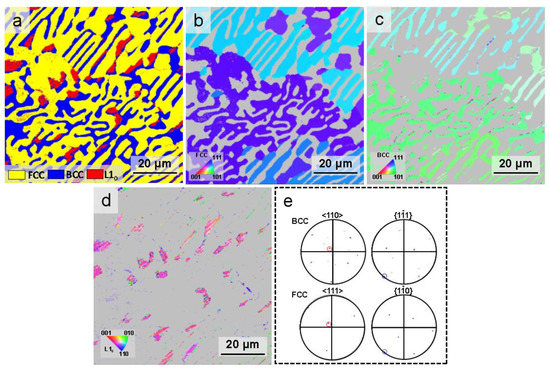
Figure 4.
EBSD results of the as-cast Co39.2Ni39.2Al21.6 EMEA. (a) Phase map; (b) IPF map of FCC phases; (c) IPF map of BCC phases; (d) IPF map of L10 phases; (e) pole figures of FCC and BCC phases in a single eutectic colony. The pole points on the (1-11) (blue circle) and [110] (red circle) pole figures of the BCC phase overlap with those on the (1-10) (blue circle) and [111] (red circle) pole figures of the FCC phase, implying the preferred orientation relationship.
It is obvious that a large fraction of the BCC phase (the blue zone) has been translated into L10 martensite (the red zone), whereas this transformation is seldom activated in other regions. Tanaka et al. [32] found that the martensite phase could not be fully transformed even when the external temperature dropped below the transition temperature; furthermore, the accumulated internal stress would be difficult to distribute homogenously. These factors will greatly impact the transformation efficiency. For convenience of the analysis of the nano-scale lamellar structures presented in the BCC phases, a further EBSD characterization was performed at high magnification for a typical FCC/BCC region with a large number of aligned nano-scale lamellar structures, and the results are shown in Figure 5. It was easily confirmed that the L10 phases (the red region) are characterized by a lathe-like morphology (Figure 5a). The martensite grains of the two main orientations are arranged in alternation (Figure 5b). A subset with BCC and two variants was chosen to further analyze the orientation relationship between L10 martensite and BCC austenite. The phase map and IPF map of the subset are presented in Figure 5c,d, respectively. Generally, the formation of martensite phase, accompanied by the occurrence of variants with different preferential directions of growth, complied with the adjacent austenite phase. It should be pointed out that the variants with a fine lamellar structure should be more compatible with austenite in order to lower the system energy [33,34,35]. In this case, two different types of martensite variant form (variant 1 and 2; marked in orange and blue, respectively); the pole figures of those variants and the remaining austenite (BCC) are presented in Figure 5e,f, respectively, where it can be observed that the orientation relationship between the two L10 martensite variants and the BCC austenite is <110>M//<001>A; {1-11}M//{1-10}A.
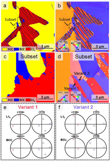
Figure 5.
EBSD results of BCC regions with nano-scale lamellar structures at high magnification. (a) Phase map; (b) IPF map; (c) phase map of the subset; (d) IPF map of the subset; (e) pole figures of variant 1 and BCC austenite. The pole points on the (111) (blue circle) and [110] (red circle) pole figures of the L10 phase (Variant 1) overlap with those on the (1-10) (blue circle) and [001] (red circle) pole figures of the BCC austenite phase; (f) pole figures of variant 2 and BCC austenite. The pole points on the (111) (blue circle) and [110] (red circle) pole figures of the L10 phase (Variant 1) overlap with those on the (1-10) (blue circle) and [001] (red circle) pole figures of the BCC austenite phase, implying the preferred orientation relationship.
3.2. Solidification Microstructures under Different Magnetic Intensities
Figure 6 presents representative SEM images of the longitudinal section of the samples solidified under a static magnetic field of 0 T, 5 T and 10 T at different magnifications. The direction of the magnetic field is parallel to the longitudinal direction. The solidified samples follow a near-equilibrium solidification mode at an extremely low cooling rate. In the absence of a magnetic field (0 T), as shown in Figure 6a1, the microstructure mainly consisted of several herringbone eutectics without an obvious primary phase, characterized by the straight regular lamellar structures in the center and vermicular anomalous eutectics at the edge. The size of the herringbone eutectics increased in this condition compared to the as-cast sample prepared in an arc-melting furnace (compared to Figure 2a). In Figure 6a2, at a larger magnification, the boundary between eutectic colonies is marked with yellow dashed lines, while orange dashed lines are used to distinguish the boundaries between the regular eutectic and the anomalous eutectic, marked as VRE and VAE, respectively, and the volume fraction of the anomalous eutectic is identified to be about 38.35%, which is higher than that in the as-cast sample. To determine the inter-spacing distance of the regular lamellar eutectics, the aforementioned line intercept method was adopted, and the average inter-lamellar spacing was determined to be 3.3 μm using Equation (1), which is three times wider than that in the as-cast alloy. According to previously published results, the considerable amount of anomalous structure originated from the subsequent partial remelting of the pre-formed eutectic structure due to recalescence [36,37], whereas the arc-melted samples (as-cast) solidified in a water-cooled copper mold, and quickly released their latent heat. Therefore, partial remelting was less likely to produce a large volume of anomalous eutectics. Additionally, the slow solidification with no magnetic field was not able to refine the lamellar structure without a considerable undercooling effect, resulting in increased spacing and anomalous eutectic content.
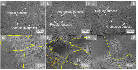
Figure 6.
The cross-section SEM back-scattered electron images paralleled to the external magnetic field B. (a1,a2) 0 T sample; (b1,b2) 5 T sample; (c1,c2) 10 T sample. The dashed-yellow lines show the boundaries of the eutectic colonies. The solid white line in (b2) show the whole thickness of several lamellae, then the interspace of lamellae could be calculated by aforementioned line intercept method by Equation (1).
After applying a magnetic field at 5 T and 10 T (Figure 6b1,b2,c1,c2, respectively), the microstructure exhibits similar characteristics to those without the application of a magnetic field, being composed of regular and anomalous eutectics. No evident alignments of eutectics along the direction of the magnetic field can be observed, illustrating that the unique eutectic morphology remained stable under the magnetic field.
By measuring the fraction of anomalous eutectics (VAE) and the inter-lamellar spacing under different magnetic field intensities during the solidification process (Figure 7), it was found that the anomalous eutectic content increased to 52.41%, while the inter-lamellar spacing decreased to 2.55 μm under a magnetic field with a strength of 5 T. When the intensity of the magnetic field was further increased to 10 T, the volume fraction of the anomalous eutectic further increased to 55.14%, while the inter-lamellar spacing between the lamellar eutectics decreased to approximately 1.93 μm. In other words, the regular eutectics were greatly refined and the evolution of regular eutectics to anomalous eutectics was promoted with increasing magnetic field intensity.
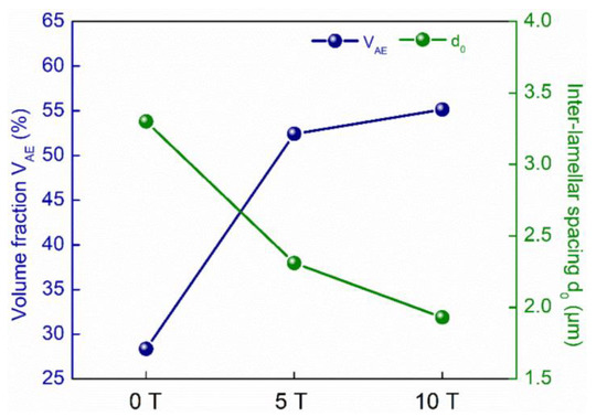
Figure 7.
The average inter-lamellar spacing (d0) and fraction of anomalous eutectics (VAE) as a function of magnetic field intensity.
The EDS results obtained for the 0 T, 5 T and 10 T samples are shown in Figure 8. The higher-magnification SEM images obtained for the three samples are shown in Figure 8a–c, where it can be observed that the nanoscale L10 layers are distributed in the dark phase (BCC) of the eutectics. Apart from this, Figure 8 (a1–a3)–(c1–c3) show the distribution of Co, Ni and Al elements, respectively. This indicates that the FCC phases (including the regular eutectic and the anomalous eutectic) are enriched in Co element, while the BCC phases (including the regular eutectic and the anomalous eutectic) are enriched in Al element. The distribution of Ni element in both FCC and BCC phases presents no significant differences. Additionally, the composition of the L10 phase also seems to be identical to that of the BCC phases, indicating the occurrence of a non-diffusion-controlled phase transition. The specific chemical compositions of different regions in each sample are listed in Table 1, as determined by point scanning of the dual phases for the straight lamellar structures and the anomalous lamellar structures. The results shown in Table 2 indicate that the chemical constituents of the FCC and BCC phases are comparable to those in the FCC and BCC phases of the as-cast alloy (Table 1). Moreover, negligible fluctuations in composition can be identified between regular eutectic and anomalous eutectic. Therefore, it can be concluded that the magnetic field imposes an insignificant effect on the phase constituents.
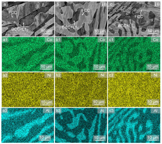
Figure 8.
EDS results for the (a) 0 T sample; (b) 5 T sample; (c) 10 T sample. (The subscripts 1–3 for a, b and c denote the EDS mapping results of Co, Ni and Al elemental composition, respectively).

Table 2.
EDS results for the 0 T, 5 T and 10 T samples.
To obtain more direct evidence of the microstructure evolution and to determine the effect of the strong magnetic field on the microstructure of the Co-Ni-Al EMEA, EBSD analyses were conducted for those three samples. Figure 9 shows the phase maps and the corresponding pole figures for the structures in the Co39.2Ni39.2Al21.6 EMEA in the case with no magnetic field applied (0 T). The phase map given in Figure 9a confirms that the eutectics consisted of FCC and BCC phases, and that the fraction of L10 phase (the red region) increased because of the martensite transformation of the BCC austenite phase (the blue region). The regular straight lamellar structures are arranged in a crisscross pattern, and the curved anomalous eutectics were also mutually overlapping, forming a series of herringbone structures. The IPF maps of the FCC, BCC and L10 phases are provided in Figure 9b–d. It can be observed that both the FCC and BCC phases of the regular eutectic follow the same orientation within a single herringbone colony, which is in agreement with the typical coupled growth of regular eutectics.
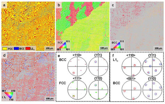
Figure 9.
EBSD results for the 0 T sample. (a) Phase map; (b) IPF map of FCC phases; (c) IPF map of BCC phases; (d) IPF map of L10 phases; (e) pole figures of FCC and BCC phases in a single eutectic colony. The pole points on the (1-11) (blue circle) and [110] (red circle) pole figures of the BCC phase overlap with those on the (1-10) (blue circle) and [111] (red circle) pole figures of the FCC phase; (f) pole figures of L10 martensite and BCC austenite. The pole points on the (1-11) (blue circle) and [110] (red circle) pole figures of the L10 phase overlap with those on the (1-10) (blue circle) and [001] (red circle) pole figures of the BCC austenite phase, implying the preferred orientation relationship.
Comparing the {110} and {111} pole figures of the FCC and BCC phases in a single eutectic colony (Figure 9e), it can be inferred that the orientation relationship between the two phases is <110>BCC//<111>FCC; {1-11}BCC//{1-10}FCC, remaining stably the same as that in the as-cast sample. This indicates that, with slow solidification, it was difficult to break the coupled growth mechanism characteristic of eutectics due to the stable solute transportation along the S/L interface. Unexpectedly, the coarser irregular phases in the anomalous eutectic also follow the same orientation as the couple-grown eutectic phases in the center of the herringbone structures. Figure 9f shows the pole figures of the BCC and L10 martensite phases. It can be confirmed that the orientation relationship between the two phases remains <110>M//<001>A; {1-11}M//{1-10}A, which means that the martensite transition corresponds precisely to the K-S relationship. In this case, the amount of the L10 phase seems to have increased near the anomalous region. Dilibal et al. [32,34] indicated that the martensite transformation process is strongly related to the austenite/secondary phase interface. The reduction in interface energy due to the ripening of the anomalous phase could ease the internal stress induced by the FCC phase, contributing to the transformation process and thus enhancing the fractions of the L10 structures.
Figure 10 shows the EBSD results for the sample solidified under a magnetic field with a strength of 5 T. As shown in the phase map (Figure 10a), the phase constituents exhibit the same characteristics. The FCC and BCC phases make up herringbone structures consisting of straight lamellar eutectics and the anomalous eutectics; similarly, the L10 phase is mainly distributed on the coarse anomalous eutectics, while a considerable amount of BCC austenite, i.e., untransformed patent phase, is distributed in the thinner regular lamellar eutectics as a result of the increased impediment to transformation presented by the soft FCC lamellar structure [35]. The corresponding IPF map of the FCC, BCC and L10 phases is presented in Figure 10b–d. The FCC and BCC phases also maintain a similar orientation in a single colony, while random distributions are presented among different colonies, i.e., the macro texture is not able to form under a magnetic field with a strength of 5 T. The orientations in the anomalous eutectic are also similar to those in the lamellar phase. According to the pole figures presented in Figure 10e, the BCC and FCC phases follow the K-S orientation relationship in both the regular eutectics and the anomalous eutectics. This demonstrates that the application of a magnetic field with a strength of 5 T during the solidification process does not change the eutectic growth mode. Figure 10f presents the orientation relationship between the BCC and L10 martensite phases, confirming that the two phases follow the <110>M//<001>A; {1-11}M//{1-10}A orientation relationship.
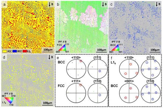
Figure 10.
EBSD results for the 5 T sample. (a) Phase map; (b) IPF map of FCC phases; (c) IPF map of BCC phases; (d) IPF map of L10 phases; (e) pole figures of FCC and BCC phases in single eutectic colony. The pole points on the (1-11) (blue circle) and [110] (red circle) pole figures of the BCC phase overlap with those on the (1-10) (blue circle) and [111] (red circle) pole figures of the FCC phase; (f) pole figures of L10 martensite and BCC austenite. The pole points on the (1-11) (blue circle) and [110] (red circle) pole figures of the L10 phase overlap with those on the (1-10) (blue circle) and [001] (red circle) pole figures of the BCC austenite phase, implying the preferred orientation relationship.
The EBSD analysis of the samples solidified under a magnetic field with a strength of 10 T are shown in Figure 11. In this condition, the phase constituent was not affected by the magnetic field (Figure 11a). The transformed L10 structures were predominantly precipitated, rather than austenite BCC phase. As shown in the IPF maps of the three phases in Figure 11b–d, the FCC and BCC phases also share the same orientation within a single herringbone structure. The pole figures presented in Figure 11e,f individually demonstrate that the two couple-grown eutectic phases still conform to the K-S orientation relationship, while the martensite also has the same orientation relationship with the BCC phase, indicating that the increase in magnetic field intensity hardly affected the eutectic structure or martensitic transformation.
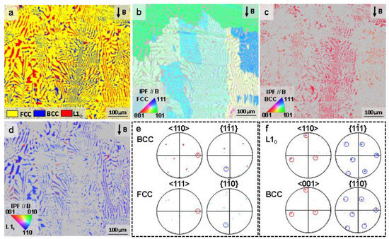
Figure 11.
EBSD results for the 10 T sample. (a) Phase map; (b) IPF map of FCC phases; (c) IPF map of BCC phases; (d) IPF map of L10 phases; (e) pole figures of FCC and BCC phases in single eutectic colony. The pole points on the (1-11) (blue circle) and [110] (red circle) pole figures of the BCC phase overlap with those on the (1-10) (blue circle) and [111] (red circle) pole figures of the FCC phase; (f) pole figures of L10 martensite and BCC austenite. The pole points on the (1-11) (blue circle) and [110] (red circle) pole figures of the L10 phase overlap with those on the (1-10) (blue circle) and [001] (red circle) pole figures of the BCC austenite phase, implying the preferred orientation relationship.
3.3. Mechanical Properties of Samples under Different Magnetic Intensities
Figure 12 shows representative room temperature compression stress–strain curves for the solidified Co39.2Ni39.2Al21.6 EHEAs under different magnetic field intensities. The yield strength (σ0.2), ultimate strength (ε) and strain to fracture (σf) were obtained, and are presented in Table 3. According to the Hell–Petch relation [38], the finer the microstructure becomes, the greater the number of grain boundaries, leading to higher resistance to dislocation motions. Therefore, reductions in grain size usually result in increased material strength. It is apparent that an excellent value of σ0.2 (1107.69 ± 3.91 MPa) was achieved in the as-cast alloy, as a result of the refined lamellar structures with less coarse anomalous eutectic content. After solidification at a slow cooling rate (near-equilibrium state), the inter-spacing of the lamellar and anomalous eutectics increased, resulting in a decrease in σ0.2 without the application of the magnetic field (815.39 ± 7.62 MPa). Although increasing the intensity of the magnetic field resulted in a refining of the lamellar structures to some extent, the fraction of anomalous eutectic with a greater inter-spacing was significantly increased due to the instability of the interface. It is possible that the latter factor played a dominant role in the lowering of the σ0.2, meaning that the σ0.2 decreased continuously after the application of the magnetic field. In addition, the plasticity, which is also greatly affected by the eutectic morphology, also decreased monotonously from 42.49 ± 2.12% (as-cast) to 36.83 ± 4.3% (10 T) [39]. The application of a magnetic field under slow solidification enabled the transition of the ductile FCC phase and the fragile BCC phase from thin lamellar to thick “stripe-like” morphologies (coarse anomalous eutectics). The thicker FCC phase acted as an “energy absorber”, enhancing the plasticity; however, the interface between the coarse and irregular BCC phase and the brittle L10 layers inevitably increases in size, which is beneficial for crack propagation, and therefore concurrent reductions in both strength and plasticity.
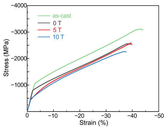
Figure 12.
Compressive stress–strain curves for the as-cast, 0 T, 5 T and 10 T samples.

Table 3.
Yield strength (σ0.2), ultimate strength (ε) and strain to fracture (σf) results for the as-cast, 0 T, 5T and 10 T samples.
4. Discussion
The above results demonstrate that the phase constitution and orientations are not sensitive to increased magnetic field intensities, while the herringbone microstructure morphology is clearly modified. That is, the inter-spacing of the straight lamellar eutectics decreased continuously, while the fraction of anomalous eutectics increased, which should be highly dependent on the solidification process.
4.1. Influence of a High-Intensity Magnetic Field on Straight Eutectic Spacing
Generally, the inter-spacing in straight lamellar structures is greatly influenced by the solute diffusion process, where any turbulence in the diffusion behavior at the liquid–solid interface can lead to alterations in eutectic spacing. Hence, it is reasonable to attribute the change in the eutectic spacing to the effect of the magnetic field on diffusion.
In the Co-Ni-Al eutectic alloy, the lamellar structure consists of the BCC phase (which is Al-rich) and the FCC phase (which is Co-rich). During eutectic growth in the absence of a high-intensity magnetic field, as the BCC phase grows, it ejects extra Co atoms into the liquid, while the growing FCC phase ejects Al atoms. Therefore, the buildup of Co atoms and Al atoms occurs in front of the alternating BCC and FCC phases, respectively (as shown in Figure 13). Under a natural convection mode during solidification, strong thermal convection in front of the S/L interface and its gradient and flow velocity could contribute to a shift in the solute concentration field and a super-cooling of eutectic growth, enhancing the diffusion rate of the solute away from the liquid–solid interface and thus resulting in wider eutectic spacing. The effect of convection on inter-spacing in the context of eutectic growth can be expressed as follows [40]:
where λ is the inter-spacing of lamellar structures in the presence of convection, λ0 is the eutectic spacing without convection, v and D are the growth velocity and solute diffusion coefficient of the phases, and u is the fluid transverse velocity. It can be easily found that increased values of D and u can result in wider spacings of lamellar structures without the application of a magnetic field.
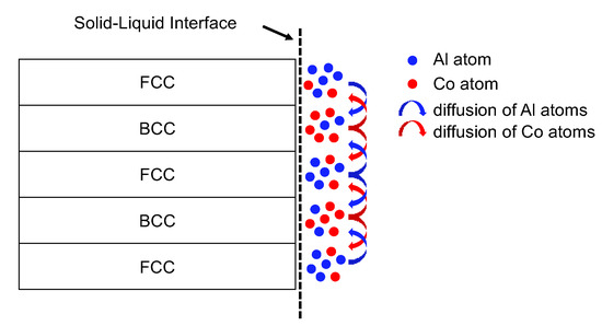
Figure 13.
Schematic diagram of atomic diffusion in front of the solid–liquid interface during eutectic growth.
It is widely accepted that magnetic fields are able to stimulate a Lorentz force, thus suppressing convection and thereby decreasing the gradient of flow velocity when a critical value is reached, owing to the effects of the magnetic field in suppressing natural convection and inducing thermo-electromagnetic convection [41]. Meanwhile, the diffusion coefficient is also decreased. The diffusion equation coinciding with Fick’s second law controlled by a strong magnetic field can be described as follows [42]:
where C is the concentration of the atoms, μ is the mobility (i.e., the steady velocity, acquired under the action of unit force). This result means that the atoms have an effective diffusion coefficient (Deff) under the magnetic field that exhibits a non-monotonic variation with increasing magnetic field intensity. Therefore, the Deff would first increase and then decrease, which is related to the external magnetic field B. The critical value BC can be expressed as follows [43]:
where S, σ, ρ and L represent the Seeback coefficient, conductivity, and density of the sample, respectively, and L denotes the average characteristic length scale of the lamellar eutectic phase. The data for calculating the critical magnetic field intensity (BC) are shown in Table 4. Then, the critical magnetic field threshold BC was obtained as about 0.8 T, indicating that under our solidification conditions, the magnetic field was able to precisely suppress the melt convection and retard the diffusion rate, thus decreasing the inter-spacing of the lamellar structures.

Table 4.
Physical properties of the Co-Ni-Al alloy.
It must be noted that in the present case, the values of S and D are approximate, but the order of magnitude is reasonable when compared with that of pure Co, Ni and Al metals [44,45]. Moreover, the temperature gradient under the action of external force is difficult to estimate accurately. If the parameters are accurately numerically estimated, the effective diffusion coefficient under a given magnetic flux density can be further quantitatively described, as mentioned above.
In addition, owing to the fact that Al is paramagnetic and Co is ferromagnetic, the magnetic field was stronger in the layers enriched with Co atoms compared to in those layers enriched with Al atoms. Subsequently, the gradient in the magnetic field yielded enhanced layers in front of the liquid/solid interface with the application of magnetic force and the solute element was imposed to perform redistribution near the interface. Therefore, the magnetic force per unit volume on the solute element can be expressed as follows [46]:
where B and ∇B are the magnetic flux density and the gradient along the solidification direction, respectively. This magnetic force restrains the interdiffusion of Co and Al atoms. Consequently, the applied magnetic field slows the atomic diffusion and decreases the diffusion coefficient (Deff). The eutectic spacing is given by [47]:
where k and Γ are the equilibrium partition coefficients and the Gibbs–Thomson coefficient, respectively, CE is the eutectic composition, and m1 and m2 are the slopes of the liquidus lines of L/BCC and L/FCC, respectively. Due to the decrease in the diffusion coefficient when B surpasses 0.8 T, the magnetic field effectively decreases the eutectic spacing. Moreover, the magnetic force will increase as B rises. Therefore, with increasing magnetic field intensity, the decrease in the diffusion coefficient is enhanced, and the eutectic spacing decreases.
As discussed above, high-intensity magnetic fields can significantly suppress the convection caused by the temperature gradient, which can significantly decrease the diffusion coefficient. That is, the application of a high-intensity magnetic field should reduce the eutectic spacing by decreasing the diffusion of the solute at the liquid–solid interface.
4.2. Formation of Anomalous Eutectics in Herringbone Structures and Their Evolution under a Strong Magnetic Field
On the basis of the above observations, the fraction of irregular vermicular eutectics (anomalous eutectics), developing at the fringe of the herringbone structures, increased continuously with increasing intensity of the external magnetic field. The origin of anomalous eutectics is a subject of considerable interest, and this research field has developed rapidly. A widely held assumption suggests that remelting by the lamellar structures occurs due to the release of latent heat by the precipitation of primary solids, thus explaining the formation of anomalous eutectics in many systems [36]. Some verification experiments [37] have also been performed in which the alloys were reheated to below their eutectic temperature in order to stimulate the recalescence process, proving that the anomalous eutectics evolved from regular eutectics.
Unfortunately, anomalous eutectic morphology is rare in EHEAs/EMEAs. The undercooling in our ternary system, with a significant medium-entropy effect, can be regarded as being negligible, i.e., the remelting of regular lamellar would hardly make sense in the context of this slow solidification. This raises an interesting question as to whether the origin of these anomalous eutectics could be the remelting of regular eutectic?
H. Dong et al. [48] found that the capillary forces arising due to the difference in the curvature between the lamellae’s termination tip and the adjacent flat interface were able to induce extra atom migration from the termination tip to the flat interface if enough time remained for solidification, leading to the destabilization of the lamellar structures. Additionally, solute supersaturation is another key factor in destabilization, and predominates during rapid solidification. In Co-Ni-Al systems, the BCC and FCC phases are both solid solution phases, i.e., supersaturation could easily happen. As discussed above, the application of the magnetic field enhanced the buildup of solute in front of the solid–liquid interface. This created a steeper solute gradient (Gc) inside the lamellar, potentially yielding a greater driving force for solute diffusion. Therefore, recession of the termination tip and the build-up of material on the flat interface adjacent to the termination tip occurred. This mass transportation process led to the formation of rod-like structures or granules along the length of the lamellar structure via further mass transportation. In addition, the capillary force then, together with the solute supersaturation, eventually leads to the break-up of the lamellar structure, a process that was accelerated significantly by the magnetic field. That is, more regions adjacent to the termination of the lamellar structure will eventually transform into an anomalous granular morphology, governed by the driving force of the magnetic field, and subsequently ripen. Therefore, the increase in the fraction of anomalous eutectics should be attributed to the increased destabilization of the lamellar eutectic structures induced by the application of the magnetic field [15].
In addition to this, many reports have also proved that thermoelectric magnetic force (TEMF) can be yielded, which can play a critical role in the morphological modification by acting on the solid–liquid interface and the interphase interface [49,50]. Therefore, it is possible that the TEMF influences the process of interface destabilization, which should be further investigated and characterized in future work.
5. Conclusions
In the present work, a Co39.2Ni39.2Al21.6 EMEA with a fully eutectic morphology was obtained using an arc-melting furnace; then, the influence of applying a high-intensity magnetic field on its microstructure following solidification was studied in detail. The main results can be listed as follows:
- (1)
- The original microstructure of the Co39.2Ni39.2Al21.6 EMEA was characterized by FCC/BCC mixed-phase herringbone eutectics consisting of curved wormy anomalous eutectics, and straight lamellar eutectics in the center. The FCC and BCC phases were enriched in Co and Al elements, respectively. A large number of nano-size L10-type martensite layers distributed on the BCC lamellar structure were also present. the orientation relationship between the FCC/BCC lamellar structures and L10/BCC lamellar structures were: <110>BCC//<111>FCC, {1-11}BCC//{1-10}FCC; {100}BCC//{110}M, <001>BCC//<1-10>M.
- (2)
- With increasing magnetic field intensity, the herringbone eutectic structure remained stable, without the formation of the primary phase, and the chemical fluctuation was observed were negligible. Meanwhile, the orientation relationships in the eutectic structures remained unchanged.
- (3)
- With increasing magnetic field intensity, the lamellar spacing of the regular lamellar eutectic decreased significantly from 3.3 μm (0 T) to 1.93 μm (10 T); in contrast, the volume fraction of anomalous eutectics increases from 28.35% (0 T) to 55.14% (10 T).
Author Contributions
Conceptualization, Y.H.; methodology, H.L. and Y.W.; software, C.X.; validation, F.B. and Y.H.; formal analysis, X.L.; investigation, H.L.; resources, X.L. and Y.H.; data curation, H.L. and Y.W.; writing—original draft preparation, H.L.; writing—review and editing, H.L. and F.B.; supervision, Y.H. and F.B.; funding acquisition, Y.H. All authors have read and agreed to the published version of the manuscript.
Funding
This research was funded by the Shanghai Sailing Program, the Xi’an Association for Science and Technology Young Talents Lifting Program, and the State Key Laboratory of Solidification Processing (NPU), China (No. 2022-TS-08).
Data Availability Statement
Not applicable.
Conflicts of Interest
The authors declare no conflict of interest.
References
- Cantor, B.; Chang, I.T.H.; Knight, P.; Vincent, A.B.J. Microstructural development in equiatomic multicomponent alloys. Mater. Sci. Eng. A 2004, 375–377, 213–218. [Google Scholar] [CrossRef]
- Yeh, J.W.; Chen, S.K.; Lin, S.J.; Gan, J.Y.; Chin, T.S.; Shun, T.T.; Tsau, C.H.; Chang, S.Y. Nanostructured High-Entropy Alloys with Multiple Principal Elements: Novel Alloy Design Concepts and Outcomes. Adv. Eng. Mater. 2004, 6, 299–303. [Google Scholar] [CrossRef]
- Anwer, Z.; Umer, M.A.; Nisar, F.; Hafeez, M.A.; Yaqoob, K.; Luo, X.; Ahmad, I. Microstructure and Mechanical Properties of Hot Isostatic Pressed Tungsten Heavy Alloy with FeNiCoCrMn High Entropy Alloy Binder. J. Mater. Res. Technal. 2022, 22, 2897–2909. [Google Scholar] [CrossRef]
- Park, C.; Hwang, T.; Kim, G.D.; Nam, H.; Kang, N. Effect of the Initial Grain Size on Laser Beam Weldability for High-Entropy Alloys. Crystals 2023, 13, 65. [Google Scholar] [CrossRef]
- Wang, M.; Ma, Z.L.; Xu, Z.Q.; Cheng, X.W. Designing VxNbMoTa refractory high-entropy alloys with improved properties for high-temperature applications. Scr. Mater. 2021, 191, 131–136. [Google Scholar] [CrossRef]
- Wang, Y.; Wang, Y. High-entropy alloys in catalyses and supercapacitors: Progress, prospects. Nano Energy 2022, 104, 107958. [Google Scholar] [CrossRef]
- Zhang, Y.; Bu, Z.; Yao, T.; Yang, L.; Li, W.; Li, J. Novel BCC Ti-Al-Nb-Zr medium-entropy alloys with ultrahigh specific strength and ductility. J. Alloys Compd. 2023, 936, 168290. [Google Scholar] [CrossRef]
- Han, K.; Jiang, H.; Huang, T.; Wei, M. Thermoelectric Properties of CoCrFeNiNbx Eutectic High Entropy Alloys. Crystals 2020, 10, 762. [Google Scholar] [CrossRef]
- Lu, Y.; Dong, Y.; Guo, S.; Jiang, L.; Kang, H.; Wang, T.; Wen, B.; Wang, Z.; Jie, J.; Cao, Z.; et al. A Promising New Class of High-Temperature Alloys: Eutectic High-Entropy Alloys. Sci. Rep. 2014, 4, 6200. [Google Scholar] [CrossRef]
- Shi, P.; Li, R.; Li, Y.; Wen, Y.; Zhong, Y.; Ren, W.; Shen, Z.; Zheng, T.; Peng, J.; Liang, X.; et al. Hierarchical crack buffering triples ductility in eutectic herringbone high-entropy alloys. Science 2021, 373, 912–918. [Google Scholar] [CrossRef] [PubMed]
- Nam, S.; Kim, S.J.; Yoon, K.N.; Kim, M.J.; Quevedo-lopez, M.; Huang, J.Y.; Park, E.S.; Choi, H. Design of metastable complex-concentrated alloys through composition tailoring. Mater. Des. 2022, 224, 111391. [Google Scholar] [CrossRef]
- Singh, N.; Shadangi, Y.; Goud, G.S.; Pandey, V.K.; Shivam, V.; Mukhopadhyay, N.K. Fabrication of MgAlSiCrFe Low-Density High-Entropy Alloy by Mechanical Alloying and Spark Plasma Sintering. Trans. Indian Inst. Met. 2021, 74, 2203–2219. [Google Scholar] [CrossRef]
- Rawat, R.; Singh, B.K.; Tiwari, A.; Arun, N.; Pathak, A.P.; Shadangi, Y.; Mukhopadhyay, N.K.; Nelamarri, S.R.; Rao, A.V.; Tripathi, A. Formation of Cu-Ni enriched phases during laser processing of non-equiatomic AlSiCrMnFeNiCu high entropy alloy nanoparticals. J. Alloys Compd. 2022, 927, 166905. [Google Scholar] [CrossRef]
- Ao, X.; Xia, H.; Liu, J.; He, Q.; Lin, S. A numerical study of irregular eutectic in Al-Si alloys under a large undercooling. Comput. Mater. Sci. 2021, 186, 110049. [Google Scholar] [CrossRef]
- Dong, H.; Chen, Y.Z.; Zhang, Z.R.; Shan, G.B.; Zhang, W.X.; Liu, F. Mechanisms of eutectic lamellar destabilization upon rapid solidification of an undercooled Ag-39.9 at.% Cu eutectic alloy. J. Mater. Sci. Technol. 2020, 59, 173–179. [Google Scholar] [CrossRef]
- Chen, Z.; Zhang, Y.; Wang, S.; Zhang, Z.Y.; Tao, Q.; Zhang, P. Microstructure and mechanical properties of undercooled Fe80C5Si10B5 eutectic alloy. J. Alloys Compd. 2018, 747, 846–853. [Google Scholar] [CrossRef]
- Rahul, M.R.; Samal, S.; Phanikumar, G. Metastable microstructures in the solidification of undercooled high entropy alloys. J. Alloys Compd. 2019, 821, 153488. [Google Scholar] [CrossRef]
- Milgrāvis, M.; Krastiņš, I.; Kaldre, I.; Kalvāns, M.; Bojarevičs, A.; Beiners, T. Pulsed and Static Magnetic Field Influence on Metallic Alloys during Solidification. Crystals 2023, 13, 259. [Google Scholar] [CrossRef]
- Li, L.; Ban, C.; Zhang, R.; Zhang, H.; Cai, M.; Zuo, Y.; Zhu, Q.; Wang, X.; Cui, J. Morphological and Crystallographic Characterization of Primary Zinc-Rich Crystals in a Ternary Sn-Zn-Bi Alloy under a High Magnetic Field. Crystals 2017, 7, 204. [Google Scholar] [CrossRef]
- Dong, S.; Liu, T.; Dong, M.; Guo, X.; Yuan, S.; Wang, Q. Enhanced magnetostriction of Tb-Dy-Fe via simultaneous <111>-crystallographic orientation and -morphological alignment induced by directional solidification in high magnetic fields. Appl. Phys. Lett. 2020, 116, 053903. [Google Scholar]
- Li, X.; Gagnoud, A.; Fautrelle, Y.; Ren, Z.; Moreau, R.; Zhang, Y.; Esling, C. Dendrite fragmentation and columnar-to-equiaxed transition during directional solidification at lower growth speed under a strong magnetic field. Acta Mater. 2012, 60, 3321–3332. [Google Scholar] [CrossRef]
- Hu, S.; Dai, Y.; Gagnoud, A.; Fautrelle, Y.; Moreau, R.; Ren, Z.; Deng, K.; Li, C.; Li, X. Effect of a magnetic field on macro segregation of the primary silicon phase in hypereutectic Al-Si alloy during directional solidification. J. Alloys Compd. 2017, 722, 108–115. [Google Scholar] [CrossRef]
- Liu, J.; Zheng, H.; Huang, Y.; Xia, M.; Li, J. Microstructure and magnetic field induced strain of directionally solidified ferromagnetic shape memory CoNiAl alloys. Scr. Mater. 2005, 53, 29–33. [Google Scholar] [CrossRef]
- Dar, R.D.; Yan, H.; Chen, Y. Grain boundary engineering of Co-Ni-Al, Cu-Zn-Al, and Cu-Al-Ni shape memory alloys by intergranular precipitation of a ductile solid solution phase. Scr. Mater. 2016, 115, 113–117. [Google Scholar] [CrossRef]
- Duan, D.; Wu, Y.; Chen, H.; Wang, X.; Liu, X.; Wang, H.; Jiang, S.; Lu, Z. A strategy to design eutectic high-entropy alloys based on binary eutectics. J. Mater. Sci. Technol. 2022, 103, 152–156. [Google Scholar] [CrossRef]
- Wang, J.; He, Y.; Li, J.; Hu, R.; Kou, H.; Beaugnon, E. Experimental platform for solidification and in-situ magnetization measurement of undercooled melt under strong magnetic field. Rev. Sci. Instrum. 2015, 86, 25102. [Google Scholar] [CrossRef] [PubMed]
- Yu, J.; Ren, Z.; Ren, W.; Deng, K.; Zhong, Y. Solidification structure of eutectic Al-Si alloy under a high magnetic field-aid-electromagnetic vibration. Acta Metall. Sin. 2009, 22, 6. [Google Scholar] [CrossRef]
- Wu, Q.; He, F.; Li, J.; Kim, S.H.; Wang, Z.; Wang, J. Phase-selective recrystallization makes eutectic high-entropy alloys ultra-ductile. Nat. Commun. 2022, 13, 4697. [Google Scholar] [CrossRef] [PubMed]
- Brener, E.; Müller, K.; Temkin, D. Structure formation and the morphology diagram of possible structures in two-dimensional diffusional growth. Phys. Rev. E 1996, 54, 2714. [Google Scholar] [CrossRef]
- Efstathiou, C.; Sehitoglu, H.; Johnson, A.J.; Hamilton, R.F.; Maier, H.J.; Chumlyakov, Y. Large reduction in critical stress in Co-Ni-Al upon repeated transformation. Sci. Mater. 2004, 51, 979–985. [Google Scholar] [CrossRef]
- Maziarz, W. Structure changes of Co–Ni–Al ferromagnetic shape memory alloys after vacuum annealing and hot rolling. J. Alloys Compd. 2008, 448, 223–226. [Google Scholar] [CrossRef]
- Tanaka, Y.; Oikawa, K.; Sutou, Y.; Omori, T.; Kainuma, R.; Ishida, K. Martensitic transition and superelasticity of Co-Ni-Al ferromagnetic shape memory alloys with β + γ two-phase structure. Mater. Sci. Eng. A 2006, 438–440, 1054–1060. [Google Scholar] [CrossRef]
- Cui, J.; Chu, Y.S.; Famodu, O.O.; Furuya, Y.; Hattrick-simpers, J.; James, R.D.; Ludwig, A.; Thienhaus, A.; Wutting, M.; Zhang, Z.; et al. Combinatorial search of thermoelastic shape-memory alloys with extremely small hysteresis width. Nat. Mater. 2006, 5, 286–290. [Google Scholar] [CrossRef] [PubMed]
- Dilibal, S.; Sehitoglu, H.; Hamilton, R.F.; Maier, H.J.; Chumlyakov, Y. On the volume change in Co-Ni-Al during pseudoelasticity. Mater. Sci. Eng. A 2011, 528, 2875–2881. [Google Scholar] [CrossRef]
- Hamilton, R.F.; Sehitoglu, H.; Efstathiou, C.; Maiar, H.J.; Chumlyakov, Y.; Zhang, X.Y. Transformation of Co-Ni-Al single crystals in tension. Sci. Mater. 2005, 53, 131–136. [Google Scholar] [CrossRef]
- Wei, X.X.; Lin, X.; Xu, W.; Huang, Q.S.; Ferry, M.; Li, F.J.; Zhou, Y.H. Remelting-induced anomalous eutectic formation during solidification of deeply undercooled eutectic alloy melts. Acta Mater. 2015, 95, 44–56. [Google Scholar] [CrossRef]
- Yang, L.; Liu, L.J.; Qin, Q.Y.; Li, J.F. Role of Remelting in Grain Refinement of Undercooled Single-Phase Alloys. Metall. Mater. Trans. A 2022, 53, 3100–3109. [Google Scholar] [CrossRef]
- Bayram, Ü.; Maraşlı, N. Influence of Growth Rate on Eutectic Spacing, Microhardness, and Ultimate Tensile Strength in the Directionally Solidified Al-Cu-Ni Eutectic Alloy. Metall. Mater. Trans. B 2008, 49, 3293–3305. [Google Scholar] [CrossRef]
- Yin, y.; Tan, Q.; Wang, T.; Kent, D.; Mo, N.; BermingHam, R.; Li, H.; Zhang, M.X. Eutectic modification of Fe-enriched high-entropy alloys through minor addition of boron. J. Mater. Sci. 2020, 55, 14571–14587. [Google Scholar] [CrossRef]
- Xu, B.; Tong, W.; Kang, T.Y.; Zuo, L.; He, J.C. The Lamellar Eutectic Spacing Changes under the High Magnetic Field during the Diffusion of Liquid Al/Solid Cu Process. Adv. Mat. Res. 2010, 160–162, 603–607. [Google Scholar]
- Wang, P.; Shuai, S.; Huang, C.; Liu, X.; Fu, Y.; Wang, J.; Ren, Z. Revealing the influence of high magnetic field on the solute distribution during directional solidification of Al-Cu alloy. J. Mater. Sci. Technol. 2021, 88, 226–232. [Google Scholar] [CrossRef]
- Kasuga, M.; Takano, T.; Akiyama, S.; Hiroshima, K.; Yano, K.; Kishio, K. Growth of ZnO films by MOCVD in high magnetic field. J. Cryst. Growth 2005, 275, 1545–1550. [Google Scholar] [CrossRef]
- Bu, F.; Zhang, Y.; Liu, H.; Wang, J.; Beaugnon, E.; Li, J.; He, Y. Magnetic field intensity dependent microstructure evolution and recrystallization behavior in a Co–B eutectic alloy. J. Mater. Sci. Technol. 2023, 138, 93–107. [Google Scholar] [CrossRef]
- Hardianto, A.; Mey, G.D.; Malengier, B.; Langenhove, L.V.; Hertleer, C. Textile yarn thermocouples for use in fabrics. J. Eng. Fibers Fabr. 2019, 14, 1–7. [Google Scholar] [CrossRef]
- Kishore, R. Electrical conductivity of metals. Phys. Status Solid 1968, 26, 133–138. [Google Scholar] [CrossRef]
- Li, X.; Fautrelle, Y.; Gagnoud, A.; Ren, Z.; Moreau, R. High Magnetic Field-Induced Formation of Banded Microstructures in Lamellar Eutectic Alloys During Directional Solidification. Metall. Mater. Trans. A 2016, 47, 4038–4052. [Google Scholar] [CrossRef]
- Li, X.; Ren, Z.; Fautrelle, Y. Effect of a high axial magnetic field on the microstructure in a directionally solidified Al–Al2Cu eutectic alloy. Acta Mater. 2006, 54, 5349–5360. [Google Scholar] [CrossRef]
- Dong, H.; Chen, Y.Z.; Wang, K.; Shan, G.B.; Zhang, Z.R.; Zhang, W.X.; Liu, F. Modeling remelting induced destabilization of lamellar eutectic structure in an undercooled Ni-18.7 at.% Sn eutectic alloy. J. Alloys Compd. 2020, 826, 154018. [Google Scholar] [CrossRef]
- Li, X.; Fautrelle, Y.; Gagnoud, A.; Ren, M.; Moreau, R. EBSD Study of the Influence of a High Magnetic Field on the Microstructure and Orientation of the Al-Si Eutectic During Directional Solidification. Metall. Mater. Trans. A 2016, 47, 2952–2963. [Google Scholar] [CrossRef]
- Yu, J.; Du, D.; Ren, Z.; Fautrelle, Y.; Moreau, R.; Li, X. Influence of an Axial Magnetic Field on Microstructures and Alignment in Directionally Solidified Ni-based Superalloy. ISIJ Int. 2017, 57, 337–342. [Google Scholar] [CrossRef]
Disclaimer/Publisher’s Note: The statements, opinions and data contained in all publications are solely those of the individual author(s) and contributor(s) and not of MDPI and/or the editor(s). MDPI and/or the editor(s) disclaim responsibility for any injury to people or property resulting from any ideas, methods, instructions or products referred to in the content. |
© 2023 by the authors. Licensee MDPI, Basel, Switzerland. This article is an open access article distributed under the terms and conditions of the Creative Commons Attribution (CC BY) license (https://creativecommons.org/licenses/by/4.0/).