Abstract
Lanthanum oxide powder was added to improve the microstructure and properties of a Ti-6Al-4V alloy part during cold metal transfer (CMT) based on wire arc additive manufacturing (WAAM). The macrostructure, microstructure and properties of the part were studied by using an optical microscope (OM), scanning electron microscope (SEM), electron backscatter(ed) diffraction (EBSD), microhardness evaluation and a tensile test. The results showed that the β grain size and martensite (α) size were reduced by adding lanthanum oxide powder. The texture intensity of the part also decreased due to the change in microstructure. Accordingly, the microhardness and tensile properties of the part obtained by adding lanthanum oxide were improved. In addition, based on the interdependence theory model, adding La2O3 particles in the molten pool as heterogeneous nucleation points could reduce the distance of XSD, so fine equiaxed β grains can be formed in the deposition layer.
1. Introduction
Wire arc additive manufacturing (WAAM) is widely applied in metal additive manufacturing owing to its low cost and high efficiency [1,2,3], which is derived from traditional arc deposition technology and belongs to the direct energy deposition (DED) techniques. Compared with other arc additive manufacturing methods, cold metal transfer (CMT) has the advantage of stable metal transfer and minimal heat input [4].
Posch et al. [5] adopted CMT to manufacture the blade-like geometry of duplex stainless steel. With consistent deposition parameters for all layers, the part obtained a smooth surface, which was the same as that obtained by hot rolling, flame-cutting or sanding. Rodriguez et al. [6] applied multi-bead CMT deposition parameters to build 316 L stainless steel walls. The average distance between the highest peak and the lowest valley of WAAM parts was 220 μm, which could be used to describe the absolute surface roughness. Cong et al. [7] studied the microstructure and properties of Al-Cu alloy additively manufactured parts obtained by CMT. Gu et al. [8] studied the effect of interlaminar rolling and post-deposition heat treatment on the porosity of 2319 and 5087 aluminum alloys prepared by CMT technology. The results showed that the pores were basically eliminated after rolling with a 45 kN load.
Rare earth can normally be used as a nucleation particle to improve the microstructure of WAAM [9,10,11]. Chen et al. [9] studied the effect of lanthanum oxide on the microstructure and tensile strength of Al alloy parts. The grain size was refined, and the tensile strength was improved. Similar results were also obtained in the TC17 alloy of WAAM-GTA [10]. Therefore, using rare earth to improve the microstructure of WAAM parts has great potential. The CMT process has the advantages of it being a simple operation and there being no spatter in the stacking process, a stable arc, a high molding quality, fine grains and few defects. At present, the CMT technique has been employed in lots of research on WAAM, especially in the WAAM of Al alloy [12,13,14]. However, there are a few studies on the WAAM-CMT of Ti alloy. Recently, Chen et al. [15] employed CMT to study the effect of its parameters on the microstructure and tensile strength of Ti-6Al-4V parts. The authors reported that the tensile properties were mainly affected by a coarse microstructure. In addition, the grain refinement of additively manufactured Ti-6.5Al-3.5Mo-1.5Zr-0.3Si titanium alloy by the addition of La2O3 was reported in the literature [9]. However, studies on lanthanide oxide controlling the WAAM-CMT of Ti-6Al-4V part have not been reported.
In this work, the microstructure in the WAAM-CMT of a Ti-6Al-4V part is improved by adding lanthanum oxide. The influence of lanthanum oxide on the WAAM-CMT of a Ti-6Al-4V part will be studied by analyzing the macrostructure, microstructure and properties. The conclusions of the present investigation will be tremendously advantageous to enhancing the microstructure and properties of Ti-6Al-4V parts built via WAAM-CMT.
2. Materials and Methods
Ti-6Al-4V alloy is also named TC4 alloy, and its chemical composition is listed in Table 1. In this paper, TC4 metal wire with a diameter of 1.2 mm was employed to build a Ti-6Al-4V alloy part. A TC4 plate with the dimension of 10 mm × 10 mm × 100 mm was used to additively manufacture the substrate.

Table 1.
Chemical composition of the TC4 metal wire.
A TPS2700 CMT welding power, supplied by the Fronius company in Austria, was used to produce TC4 thin-walled parts. A schematic diagram of the CMT additive manufacturing system is shown in Figure 1a, which mainly contains welding power, a shielding gas cover, a working platform and so on. The welding wire is connected to the positive pole of the welding power supply. The working platform is connected to the cathode of the welding power supply. There are two kinds of CMT additive manufacturing processes, including those that do not add lanthanum oxide and those that do add lanthanum oxide. The lanthanum oxide powder was dissolved by alcohol (99.99%) and evenly coated on the surface of each additively manufactured layer. The ratio of La2O3 to alcohol was 0.1 g/mL. A print net was used to ensure the uniform dispersion of La2O3 powder. The powder coating rate was 10 mg/cm2. We kept the interlayer temperature at 60 °C. The deposition speed of 8 mm/s, shielding gas flow rate of 20 L/min and deposition current of 140 A were employed as the CMT additive manufacturing parameters.
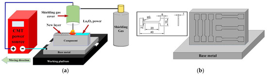
Figure 1.
Schematic diagram of CMT additive manufacturing system and tensile specimens. (a) CMT additive manufacturing system and (b) Tensile specimens.
Metallographic samples were cut from the parts perpendicular to the deposition direction by using the wire-cut electrical discharge machining technology. Abrasive paper (from 1200# to 2000#) was used to grind the metallographic samples. The specimens were etched with a solution of 4 mL HF, 8 mL HNO3 and 100 mL H2O. An optical microscope (OM) was employed to observe the macrostructure of each specimen. The scanning electron microscope (SEM) and electron backscattered diffraction (EBSD) with a step size of 2 μm were used to analyze the microstructure and grain orientation of each specimen. The electrolyte of the EBSD sample electrolytic polishing electrolyte was composed of 80% anhydrous methanol and 20% perchloric acid.
A digital micro-hardness tester (HVS-1000) was employed to measure the micro-microhardness of parts with a load of 500 g and loading time of 10 s. Two types of tensile specimen were prepared in the vertical and horizontal planes, as shown in Figure 1b. Three tensile specimens were taken from each kind of tensile specimen. The tensile test was carried out with an electronic universal testing machine at room temperature.
3. Results
3.1. Effect of La2O3 on Macrostructure
Figure 2 shows the cross-section of thin-walled parts with different CMT-AM processes. On the left side of Figure 2, cross-sections of thin-walled parts with lanthanum oxide (marked in red) are displayed. On the right side of Figure 2, cross-sections of thin-walled parts without lanthanum oxide (marked in blue) are displayed. Two thin-walled parts have the same number of deposition layers (a total of 18 layers). The height of the thin-walled part with La2O3 is basically equal to that of the thin-walled part without La2O3. Therefore, it was found that the effect of lanthanum oxide on the height of thin-walled parts is not obvious. However, the grain shape has an obvious difference between the thin-walled part without La2O3 and the thin-walled part with La2O3. In the top zone, the grain shape consisted of equiaxed and columnar crystals when the lanthanum oxide powder was added. The grain shape consisted of coarse columnar crystals when the lanthanum oxide powder was not added. The grain growth directions were parallel to the heat dissipation direction. In the middle and bottom zones, there is a similar rule for changing the grain shape.
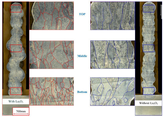
Figure 2.
Cross-section of thin-walled parts with and without La2O3.
Normally, the top layer has a bigger temperature gradient, which leads to the TC4 alloy’s preferential growth in the <101> crystal direction. So, coarse columnar crystals were obtained in the top zone of the thin-walled part without La2O3. When the lanthanum oxide powder was added during the CMT-AM process, the grain growth was not only affected by the temperature gradient but also by the lanthanum oxide powder. In addition, the thin-walled part presented large geometrical instabilities when La2O3 powder was added, as shown in Figure 2a, which may be caused by the change in arc behavior and metal transfer. Metal oxides have poor conductivity. During the CMT-AM process, it has obvious short-circuit characteristics. The poor conductivity was not conducive to arc combustion. Correspondingly, the stability of the deposition process was affected by adding La2O3 powder. Therefore, the geometry of the wall with La2O3 was poorer than that of the wall without La2O3.
3.2. Effect of La2O3 on Microstructure
Figure 3 shows the grain morphology with different thin-walled parts. Figure 3a shows the grain morphology of a thin-walled part without La2O3. It can be found that there are lots of coarse, columnar β grains of thin-walled parts in the zones at the top, middle and bottom. Especially in the middle zone, the size of the β grains exceeds 1 mm~. Figure 3b shows the grain morphology of a thin-walled part without La2O3. When La2O3 was added, a columnar-to-equiaxed transition occurred, and the β grain size was obviously reduced. M.J. Bermingham et al. [16] indicated that the free energy in La2O3 is less than that of Ti2O. La element was more easily combined with the O element compared with the Ti element. Therefore, it could be concluded that La2O3 could stably exist in a Ti alloy molten pool. Simultaneously, La2O3 and β-Ti had similar crystallographic relationships as follows:
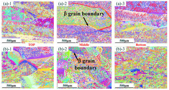
Figure 3.
Distribution of grain morphology in different zones: (a) without La2O3; (b) with La2O3. (Note: ((a)-1) and ((b)-1) show the top zone, ((a)-2) and ((b)-2) show the middle zone, and ((a)-3) and ((b)-3) show the Bottom zone).
The similar crystallographic relationship could guarantee that La2O3, as a nucleation particle, could refine the β grain size.
The distribution of elements in the middle zone of the thin-walled part is shown in Figure 4. Figure 4a shows the element distribution without La2O3. The elements in the thin-walled part were mainly composed of the Ti element, Al element and V element, which are, respectively, marked as pink, green and blue. The evenly distributed La element (marked in yellow) in the thin-walled part is shown in Figure 4b. These results indicate that an evenly distributed La element in the thin-walled part could be obtained by using the addition method in this experiment.
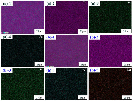
Figure 4.
Distribution of the elements: (a) without La2O3; (b) with La2O3. (Note: ((a)-1–(a)-4) show the distribution of the elements with Ti-Al-V, Ti, Al and V; ((b)-1–(b)-5) show the distribution of the elements with Ti-Al-V, Ti, Al, V and La).
SEM images and results of the EDS are shown in Figure 5. A number of acicular martensites (α) are present in the SEM image of the thin-walled part without La2O3, as shown in Figure 5a. A little lath martensite is also observed. Through the EDS results, a small amount of O element and Si element were found, which may have originated from the metallographic sample preparation process. Figure 5b shows the SEM image and EDS results of a thin-walled part with La2O3, which show an obviously different martensite shape and EDS results compared with those in Figure 5a. The martensite shape changed from a slender acicular one to a shorter acicular one when La2O3 was added. In addition, the dimension of lath martensite was also reduced by adding La2O3. There are lots of lath martensite with a length greater than 10 μm, as shown in Figure 5a. However, when La2O3 was added, the dimension of lath martensite was less than that of 10 μm.
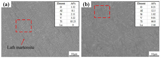
Figure 5.
SEM images: (a) without La2O3; (b) with La2O3.
Figure 6 shows the distribution of phases with different CMT-AM processes. In the figure, the red part represents the α phase, and the green part represents the β phase. The distribution of phases without La2O3 is shown in Figure 6a. The distribution of phases with La2O3 is shown in Figure 6b. We could find that there was the same phase composition in the different CMT-AM processes. More than 98% of α phase was obtained in the thin-walled parts, which was caused by the rapidly cooling process. The high-temperature β phase was formed at the high-temperature stage and was transformed into acicular martensite due to fast cooling.
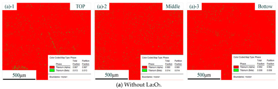
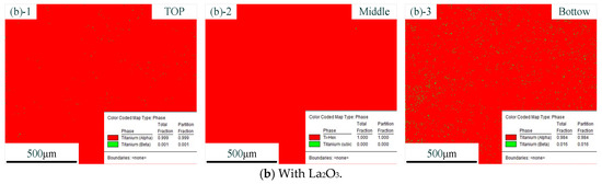
Figure 6.
Distribution of phases without La2O3 (a) and with La2O3 (b). (Note: ((a)-1) and ((b)-1) show the top zone, ((a)-2) and ((b)-2) show the middle zone, and ((a)-3) and ((b)-3) show the Bottom zone).
From the results so far, it could be concluded that the original β grains were refined obviously via adding La2O3. The original coarse β grains were transformed into fine equiaxed and columnar crystals. However, in terms of the kinds of microstructures, we did not find a difference between the part without La2O3 and the part with La2O3. The effect of La2O3 on the microstructure was mainly focused on grain refinement.
3.3. Effect of La2O3 on Grain Orientation
Figure 7 shows the orientation distribution functions (ODFs) of the thin-walled parts. The ODFs of the top zone without La2O3 and with La2O3 are shown, respectively, in Figure 7a,b. Some obvious and strong textures are shown in the top zone without La2O3, as shown in Figure 7a. The predominant texture was (3 10 1) <6 −3 1>, corresponding to the Euler space angles of 15°, 60° and 60°. The orientation distribution intensity of 42.869 was obtained. Compared with Figure 7a, the ODF of the thin-walled part with La2O3 obviously changed, as shown in Figure 7b. By adding La2O3, the initially predominant texture found in Figure 7a disappeared. Some new textures formed, as shown in Figure 7b. The new texture component was (1 11 4) <1 −5 −5>), corresponding to the Euler space angles of 15°, 75° and 5°. The maximum orientation distribution intensity is 27.545. The texture intensity obtained by the top zone with La2O3 was decreased by around one unit compared with that of the part without La2O3.
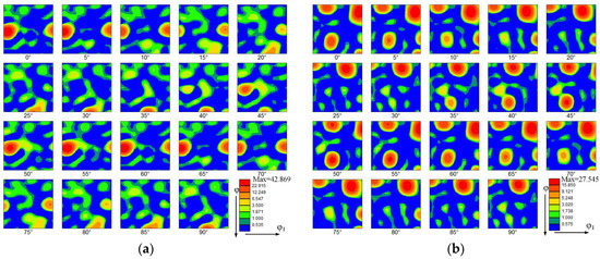
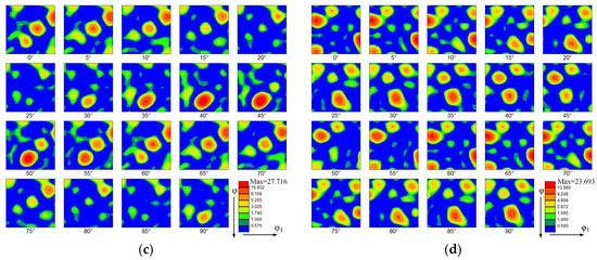
Figure 7.
Orientation distribution function (ODF). (a) The top zone without La2O3, (b) The top zone with La2O3, (c) The bottom zone without La2O3 and (d) The bottom zone with La2O3.
The ODFs of the bottom zone without La2O3 and with La2O3 are shown, respectively, in Figure 7c,d. Compared with the top zone, the texture intensities in the bottom zone were reduced. The kinds of texture have obviously also changed. The predominant texture in the thin-walled part without La2O3 was (3 3 1) <2 −3 1>, corresponding to the Euler space angles of 75°, 45° and 45°. The orientation distribution intensity of 27.716 was obtained. In the thin-walled part without La2O3, the predominant texture was (2 1 4) <1 −3 1>, corresponding to the Euler space angles of 15°, 30° and 60°. The orientation distribution intensity of 23.693 was obtained.
3.4. Effect of La2O3 on Properties
Figure 8 shows the microhardness of thin-walled parts with different CMT-AM processes. The microhardness values in the heat-affected zone (HAZ) were basically the same without La2O3 and with La2O3, which were arranged from 340 HV to 370 HV, as shown in Figure 8b. The microhardness of the thin-walled part without La2O3 was lower than that of the thin-walled part with La2O3. The max. microhardness obtained in the top zone is shown in Figure 8c. The microhardness in the top zone was about 370 HV when La2O3 was not added. The microhardness in the top zone was about 390 HV when La2O3 was added, which was increased by 20 HV compared with that of no-La2O3.
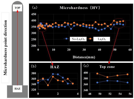
Figure 8.
Microhardness distribution. (a) the microhardness of thin-walled parts, (b) the microhardness of HAZ and (c) the microhardness of top zone.
The tensile properties of thin-walled parts are shown in Figure 9. The tensile strength of thin-walled parts in the vertical plane (VP) and the horizontal plane (HP) were measured. The tensile properties are shown in Figure 9a. The HP tensile strength was greater than that of the VP. The HP tensile strength with La2O3 was about 950 MPa, which was increased by 20 MPa compared with that of the part without La2O3. The VP tensile strength with La2O3 was about 920 MPa, which was increased by 30 MPa compared with that of the part without La2O3. The elongations of thin-walled parts are shown in Figure 9b. The HP elongations were smaller than those of the VP. The HP elongations with La2O3 were about 8.5%, which was reduced by 3% compared with that of the part without La2O3. The VP elongations with La2O3 were about 9.3%, which were reduced by 4% compared with that of the part without La2O3. The change in tensile properties was mainly affected by the change in microstructure, such as the α phase and β grain, as reported by Zhuo et al. [17]. When the β grain size was increased, the tensile strength was reduced. A decrease in α phase size would be good for increasing the tensile strength. In this work, it was found that the decrease in α and β grain sizes was achieved by adding La2O3, which was the main cause of the improvement in tensile strength.
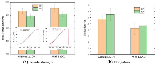
Figure 9.
Tensile properties of thin-walled parts. (a) Tensile strength of thin-walled parts and (b) Elongation of thin-walled parts.
4. Discussions
From the above results, we can see that the grain morphology and properties of thin-walled parts were obviously improved by adding La2O3. In this section, their change mechanisms are discussed in detail.
The evolution of grain morphology depends on many factors. The interdependence theory model based on alloy composition, the efficiency of nucleating particles and the distance between particles was established to predict the grain size, as reported by St John et al. [18]. The theory model is widely used in the processes of casting [19,20], welding [21] and additive manufacturing [22]. The grain size prediction in Formula (2) is expressed as follows:
where is the solute diffusion rate, is the minimum undercooling temperature required for nucleation, R is the grain growth rate, Q is the grain growth restriction factor, C0 is the solute concentration, k is the equilibrium distribution coefficient and is the solute concentration in the liquid phase at the solid–liquid interface. The XCS expressed a distance, which is used to describe dendrite growth.
Obtaining adequate undercooling ∆T could enhance nucleation. The XDL represents, at a certain position at the front of the solid–liquid interface, the distance of the gradient distribution of the solute field necessary for producing sufficient undercooling. XSD expresses the distance from XDL to the nearest effective energy nucleation particle. In this position, the alloy producing constitutional supercooling was greater than the minimum overcooling temperature required for nucleation. Figure 10 shows the evolution mechanism of grain morphology. Under the action of traditional direct current, grain morphology evolution in the deposition layer is shown in Figure 10a. It was found that due to the lack of solute elements for producing large constitutional supercooling, larger XCS and XDL were obtained. Simultaneously, due to the lack of heterogeneous nucleation points, XSD also became particularly large. Eventually, the coarse columnar β crystal was obtained and grown with multiple layers. Figure 10b shows the grain morphology by adding La2O3. Although XCS and XDL are large, there are a large number of La2O3 particles in the molten pool that act as heterogeneous nucleation points, so XSD is reduced. Therefore, fine, equiaxed grains were formed in the deposition layer by adding La2O3.
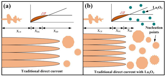
Figure 10.
Evolutionary mechanisms of grain morphology. (a) without La2O3 and (b) with La2O3.
The microstructure of the component determines the properties of the component. In the CMT-AM process, the microstructure of the components was mainly composed of β grain and martensite (α), as shown in Figure 3 and Figure 5. As can be seen from Figure 8 and Figure 9, the microhardness and the tensile strength changed. The Hall-Petch formula is given as follows:
where σ0 and αs are material constants, and dg is the grain size of the thin-walled part. It was found that the microhardness increases with the decrease in grain size. From Figure 3, in the top zone, the grain size with La2O3 was smaller than that of the part without La2O3. Therefore, the microhardness with La2O3 was greater than that of the part without La2O3. In addition, the grain size in other zones was greater than that of the top zone, and the microhardness in other zones was less than that of the top zone. The microhardness was also affected by the α phase. In lamellar titanium alloy, its ultimate tensile strength decreases with the increase in slip distance. In this work, the α phase size in the top zone was smaller than that of the other zones. The other zones were affected by multiple thermal cycles, which led to the α phase growth. When the α-lath width was increased, the strength was reduced. In addition, the slip distance depends on the size of the lath martensite. Namely, the greater the width of the martensite is, the greater the slip distance is. When La2O3 was added during the CMT-AM process, the size of the lath martensite was reduced (Figure 5). Therefore, the tensile strength without La2O3 was less than that of the part with La2O3.
5. Conclusions
- (1)
- By adding La2O3, the maximum grain diameters of the thin-walled part in the difference zones were respectively reduced by around 17.5% (top zone), 11.6% (middle zone) and 38% (bottom zone) compared with those of the part without La2O3.
- (2)
- The texture intensity of the part obtained by adding La2O3 was reduced, especially the texture intensity in the top zone. Compared with not adding La2O3, the texture intensity of adding La2O3 in the top zone was reduced from 42.869 to 27.545.
- (3)
- The microhardness of the part obtained by adding La2O3 was increased by 20 HV compared with that of the normal process. The tensile properties of the part were also improved by adding La2O3.
Author Contributions
H.L. writing—original draft and writing—review and editing; S.W. Methodology; J.L. Investigation; H.H. Data curation; Q.L. Visualization; H.C. Investigation, All authors have read and agreed to the published version of the manuscript.
Funding
This research received no external funding.
Institutional Review Board Statement
Not applicable.
Informed Consent Statement
Not applicable.
Data Availability Statement
Not applicable.
Conflicts of Interest
No conflicts of interest exist in the submission of this manuscript, and the manuscript has been approved by all authors for publication.
References
- Chen, C.; Du, W.; Zhang, H.; Zhao, X. Improvement of microstructure and mechanical properties of stainless steel TIG based wire arc additive manufacturing by using AC/DC mix current waveform. J. Mater. Res. Technol. 2023, 23, 4355–4366. [Google Scholar] [CrossRef]
- Na, X.; Wenqing, L.; Liu, Z.; Muthuramalingam, T. Effect of scandium in Al–Sc and Al–Sc–Zr alloys under precipitation strengthening mechanism at 350 C aging. Met. Mater. Int. 2021, 27, 5145–5153. [Google Scholar] [CrossRef]
- Chen, C.; Sun, G.; Du, W.; Liu, J.; Zhang, H. Effect of equivalent heat input on WAAM Al-Si alloy. Int. J. Mech. Sci. 2023, 238, 107831. [Google Scholar] [CrossRef]
- Wu, W.; Xu, W.; Xue, J.; Yao, P. Effect of cooling and CMT mode process on additive manufacturing. Mater. Manuf. Process. 2021, 37, 1298–1309. [Google Scholar] [CrossRef]
- Posch, G.; Chladil, K.; Chladil, H. Material properties of CMT—Metal additive manufactured duplex stainless steel blade-like geometries. Weld. World 2017, 61, 873–882. [Google Scholar] [CrossRef]
- Rodriguez, N.; Vázquez, L.; Huarte, I.; Arruti, E.; Tabernero, I.; Alvarez, P. Wire and arc additive manufacturing: A comparison between CMT and TopTIG processes applied to stainless steel. Weld. World 2018, 62, 1083–1096. [Google Scholar] [CrossRef]
- Cong, B.; Ding, J.; Williams, S. Effect of arc mode in cold metal transfer process on porosity of additively manufactured Al-6.3%Cu alloy. Int. J. Adv. Manuf. Technol. 2014, 76, 1593–1606. [Google Scholar] [CrossRef]
- Gu, J.; Ding, J.; Williams, S.W.; Gu, H.; Ma, P.; Zhai, Y. The effect of inter-layer cold working and post-deposition heat treatment on porosity in additively manufactured aluminum alloys. J. Mater. Process. Technol. 2016, 230, 26–34. [Google Scholar] [CrossRef]
- Chen, F.; Yang, Y.; Chen, C.; Wang, Q.; Xie, R. Effect of La2O3 particle size on the microstructure and properties of Al Si alloys deposited via wire arc additive manufacturing. J. Manuf. Process. 2021, 68, 523–533. [Google Scholar] [CrossRef]
- Chen, Y.; Yang, C.; Fan, C.; Zhuo, Y.; Lin, S.; Chen, C. Grain refinement of additive manufactured Ti-6.5Al-3.5Mo-1.5Zr-0.3Si titanium alloy by the addition of La2O3. Mater. Lett. 2020, 275, 128170. [Google Scholar] [CrossRef]
- Zhuo, Y.; Yang, C.; Fan, C.; Lin, S.; Chen, Y.; Chen, C.; Cai, X. Grain refinement of wire arc additive manufactured titanium alloy by the combined method of boron addition and low frequency pulse arc. Mater. Sci. Eng. A 2021, 805, 140557. [Google Scholar] [CrossRef]
- Yang, Q.; Xia, C.; Deng, Y.; Li, X.; Wang, H. Microstructure and Mechanical Properties of AlSi7Mg0.6 Aluminum Alloy Fabricated by Wire and Arc Additive Manufacturing Based on Cold Metal Transfer (WAAM-CMT). Materials 2019, 12, 2525. [Google Scholar] [CrossRef]
- Scotti, F.M.; Teixeira, F.R.; da Silva, L.J.; de Araújo, D.B.; Reis, R.P.; Scotti, A. Thermal management in WAAM through the CMT Advanced process and an active cooling technique. J. Manuf. Process. 2020, 57, 23–35. [Google Scholar] [CrossRef]
- Su, C.; Chen, X.; Gao, C.; Wang, Y. Effect of heat input on microstructure and mechanical properties of Al-Mg alloys fabricated by WAAM. Appl. Surf. Sci. 2019, 486, 431–440. [Google Scholar] [CrossRef]
- Chen, C.; Chen, F.; Yang, Y.; Zhang, H. Study on appearance and mechanical behavior of additively manufacturing of Ti–6Al–4V alloy by using cold metal transfer. CIRP J. Manuf. Sci. Technol. 2021, 35, 250–258. [Google Scholar] [CrossRef]
- Bermingham, M.; StJohn, D.; Krynen, J.; Tedman-Jones, S.; Dargusch, M. Promoting the columnar to equiaxed transition and grain refinement of titanium alloys during additive manufacturing. Acta Mater. 2019, 168, 261–274. [Google Scholar] [CrossRef]
- Zhuo, Y.; Yang, C.; Fan, C.; Lin, S.; Chen, C.; Cai, X. Microstructure and mechanical properties of wire arc additive repairing Ti–5Al–2Sn–2Zr–4Mo–4Cr titanium alloy. Mater. Sci. Technol. 2020, 36, 1712–1719. [Google Scholar] [CrossRef]
- StJohn, D.H.; Qian, M.; Easton, M.A.; Cao, P. The Interdependence Theory: The relationship between grain formation and nucleant selection. Acta Mater. 2011, 59, 4907–4921. [Google Scholar] [CrossRef]
- Tedman-Jones, S.N.; McDonald, S.D.; Bermingham, M.J.; StJohn, D.H.; Dargusch, M.S. Investigating the morphological effects of solute on the β-phase in as-cast titanium alloys. J. Alloys Compd. 2018, 778, 204–214. [Google Scholar] [CrossRef]
- Qiu, D.; Zhang, D.; Easton, M.A.; John, D.H.S.; Gibson, M.A. Refining As-cast β-Ti Grains Through ZrN Inoculation. Met. Mater. Trans. A 2018, 49, 1444–1449. [Google Scholar] [CrossRef]
- Yin, B.; Ma, H.; Wang, Y.; Zhao, H.; Jin, G.; Wang, J. Modeling and application of continuous growth restriction factor for elucidating development of as-welded grain size. J. Alloys Compd. 2018, 739, 901–908. [Google Scholar] [CrossRef]
- Tedman-Jones, S.N.; Bermingham, M.J.; McDonald, S.D.; St John, D.H.; Dargusch, M.S. Titanium sponge as a source of native nuclei in titanium alloys. J. Alloys Compd. 2019, 818, 153353. [Google Scholar] [CrossRef]


Disclaimer/Publisher’s Note: The statements, opinions and data contained in all publications are solely those of the individual author(s) and contributor(s) and not of MDPI and/or the editor(s). MDPI and/or the editor(s) disclaim responsibility for any injury to people or property resulting from any ideas, methods, instructions or products referred to in the content. |
© 2023 by the authors. Licensee MDPI, Basel, Switzerland. This article is an open access article distributed under the terms and conditions of the Creative Commons Attribution (CC BY) license (https://creativecommons.org/licenses/by/4.0/).