Article

Zero-Optical-Distance Mini-LED Backlight with Cone-Shaped Light Coupling Microstructures

1
School of Advanced Manufacturing, Fuzhou University, Quanzhou 362200, China
2
College of Physics and Information Engineering, Fuzhou University, Fuzhou 350108, China
3
Fujian Science & Technology Innovation Laboratory for Optoelectronic Information of China, Fuzhou 350108, China
*
Author to whom correspondence should be addressed.
Crystals 2023, 13(2), 241; https://doi.org/10.3390/cryst13020241
Submission received: 6 December 2022 / Revised: 23 January 2023 / Accepted: 26 January 2023 / Published: 31 January 2023
(This article belongs to the Special Issue Frontiers in Optics of Liquid Crystals and Displays)

Abstract

:
This paper presents a zero-optical-distance mini-LED backlight with cone-shaped light coupling microstructures to achieve an ultra-thin backlight architecture (~0.1 mm thickness) by combining the characteristics of direct-lit and edge-lit backlights. There is no gap between the light guide plate (LGP) and the reflector, as well as between the LGP and the mini-LED embedded in the reflector. The illuminance uniformity and light extraction efficiency (LEE) of the whole structure reach 91.47% and 77.09%, respectively. Nine sub-modules are spliced together to realize 2D local dimming with 0.29% crosstalk. The structure shows high optical performance while reducing the thickness of the backlight module, which is of great significance for the development of mini-LED backlights.

1. Introduction

In recent years, a number of emerging display technologies are driving the development of the display industry, such as micro-LED, organic electroluminescence display (OLED), quantum-dot photoluminescence (QDPL), quantum-dot electroluminescence (QDEL), digital light processing (DLP), and other display technologies [1,2,3,4,5,6,7]. As a kind of mature display technology, LCD has occupied the mainstream of flat panel display products due to its advantages of low cost, low power consumption, long service life, and so on [8,9,10]. The development of display technology is moving towards thin thickness, low power consumption, high definition, transparency, and flexibility. It is increasingly important to realize a thinner structure of LCD. The backlight module, as an important part, has a close relationship with LCDs. The thinness of the backlight module largely determines the LCD’s thickness [11]. The traditional direct-lit backlight uses two methods to reduce the thickness of the backlight module. One is to reduce the light mixing distance by using a large number of light sources, but this will increase the power consumption and cost. Another method is the secondary optical design of the light source to improve its illumination area [12,13,14,15]. However, the secondary optical design is complex and generally involves the application of mathematical methods or requires high accuracy in processing. Although the edge-lit backlight can effectively reduce the thickness of the backlight module, the optical performance is relatively hard to control due to the attenuation of energy during the propagation of light in the light guide plate (LGP) [16,17,18,19]. Therefore, a backlight structure that can improve the optical performance and reduce the thickness is still an urgent need for LCDs.
Recently, mini-LED technology has attracted much attention because of its advantages of low power consumption, miniaturization, wide color gamut, high dynamic range (HDR), and high contrast ratio [20,21,22,23,24]. This has facilitated the emergence of the mini-LED backlight, making mini-LEDs widely used in head-mounted displays, mobile phones, and laptops. Compared with conventional LEDs, mini-LEDs are smaller in size (50 μm~200 μm) and have a large luminous half-angle, thus reducing the thickness of the backlight module [25,26,27,28]. At the same time, mini-LED backlights have higher peak luminance for 2D local dimming, which can achieve a high contrast ratio comparable to OLEDs. At present, the mini-LED backlight has a remarkable effect on realizing the thinning of the backlight module. However, thousands of mini-LED light sources would increase the power consumption and cost of the backlight module [29,30]. Moreover, there exists a halo phenomenon in mini-LED backlights [31,32]. In response to this problem, some mini-LED backlight structures have been proposed [33]. Examples include both the mini-LED backlight with U-grooved light guiding plates [34] and the direct-lit backlight with reflective points [35]. Even so, it is still a valuable research topic to reduce the thickness of the mini-LED backlight while achieving high optical performance.
By combining the characteristics of direct-lit and edge-lit backlights, this paper proposes a new mini-LED backlight structure that realizes the “zero optical distance” between the LGP and the reflector, as well as between the LGP and the mini-LED embedded in the reflector; this structure provides a feasible way to reduce the thickness of mini-LED backlight module. At the same time, this structure combines cone-shaped light coupling microstructures, which can achieve high illuminance uniformity and light extraction efficiency, as well as the function of 2D local dimming and white balance. Moreover, this structure has advantages in reducing cost. In traditional designs, each single local dimming zone of the traditional backlight structure requires a large number of mini-LEDs [23,30]. However, each zone of the proposed structure only needs one mini-LED, which reduces the cost by reducing the use of mini-LEDs. In addition, this structure uses the cone-shaped light coupling microstructure to guide the light inside the LGP, which can make the light spread evenly in the LGP and achieve high illuminance uniformity, thereby replacing the diffuser plate in the traditional mini-LED backlight and reducing the cost. This structure could be realized by traditional processing methods such as laser processing [36], UV LIGA-like [37], UV imprinting [38,39], micro-injection molding [40], and other processing methods. These are currently mature processing methods that bring about limited increase in cost.

2. Design Principle

2.1. Optical Model

In this paper, the proposed backlight structure consists of several sub-physical partitions, in which the sub-physical partitions can be individually controlled to emit light. That means a single local dimming zone corresponds to a sub-physical partition. Functional films such as brightness enhancement films and diffuser films are placed on the upper surface of these sub-physical partitions to improve the overall optical performance. Figure 1a,b show our design example with nine individual local dimming zones, and Figure 1c shows a single local dimming zone that has an embedded shallow hole in the middle of the reflector. The size of the embedded hole is slightly larger than that of the mini-LED. The mini-LED is placed in the embedded hole with the light emitting direction towards the LGP. In order to prevent light leakage, the side walls of the embedded hole are coated with reflective material. The LGP is placed above the reflector without any distance between them. In this way, the so-called “zero optical distance” can be achieved, that is, there is no gap between the LGP and the reflector, as well as between the LGP and the mini-LED embedded in the reflector. This ensures the thickness reduction of the backlight module. At the same time, the optical performance is also required to be within an acceptable range. Here, the reflective strips are attached to the four side walls of the LGP to prevent light leakage to the adjacent zone. In order to make the light fully mixed in the LGP and to finally form a uniform surface light source above the LGP, the lower surface of the LGP is equipped with a cone-shaped light coupling microstructure above the mini-LED. Figure 2 shows the schematic of the light propagation in the LGP. As shown in Figure 2, the light from the mini-LED is reflected by the cone-shaped light coupling microstructure and then enters the LGP, thus expanding the illumination area of the mini-LED. Some of the light propagates in the LGP abiding by the total internal reflection law. Some of the light does not meet the condition of total internal reflection and then emits from the upper surface of the LGP. The other light exits from the upper surface of the LGP after diffuse reflection by the scattering dots on the lower surface of the LGP and the upper surface of the cone-shaped light coupling microstructure. In this process, the cone-shaped light coupling microstructure makes the light from the mini-LED enter the LGP as much as possible and propagate in the LGP abiding by total internal reflection.
The cross-sectional profile of the cone-shaped light coupling microstructure is a conic curve, that is, a rotating body formed by rotating the conic section 360° along the central axis, and the line shape is an ellipse.
The thickness distribution of the cone-shaped light coupling microstructure is defined by
{ ( x Δ x ) 2 a 2 + ( y + Δ y ) 2 b 2 = 1 , ( 0 Δ x a , 0 Δ y b 2 b 2 Δ 2 x a 2 , 0 x Δ x , b 2 b 2 Δ 2 x a 2 Δ y y b Δ y ) ( x Δ x ) 2 a 2 + ( y + Δ y ) 2 b 2 = 1 , ( a Δ x 0 , 0 Δ y b 2 b 2 Δ 2 x a 2 , Δ x x 0 , b 2 b 2 Δ 2 x a 2 Δ y y b Δ y ) d = b y Δ y
where d is the thickness of the corresponding cone-shaped light coupling microstructure at each incident point. Here, a and b are the elliptic equation parameters that determine the shape of the elliptic curve, which can be the upper half of the ellipse with the focal points distributed along the horizontal axis (a > b > 0) or the upper half of the ellipse with the focal points distributed along the vertical axis (b > a >0). x is the transverse distance (horizontal coordinate) between the incident point and the central incident point. △x represents the distance that the ellipse translates along the horizontal axis, and △y represents the distance that the ellipse translates along the vertical axis.
In order to achieve high illuminance uniformity, the small-angle light from the mini-LED should be guided to the far position in the LGP after being reflected by the cone-shaped light coupling microstructure. In contrast, the large-angle light from the mini-LED is incident to the close position. The slope of the cone-shaped light coupling microstructure is larger as it is closer to the central axis of the light source and similarly smaller as it is farther away. At the same time, there is an optical channel with a certain distance between the cone-shaped light coupling microstructure and the upper surface of the LGP. The light can be scattered out of the LGP through the scattering dots to compensate for the illuminance directly above the cone-shaped light coupling microstructure.

2.2. Scattering Dots

In a single local dimming zone, the light from the mini-LED is reflected by a cone-shaped light coupling microstructure and enters the LGP. On the lower surface of the LGP, the light intensity close to the light source is strong and the light intensity far from the light source is weak according to the principle of light propagation. Therefore, the density of the scattering dots near the light source is set to be small and that of dots far away from the light source is set to be large for achieving high illuminance uniformity. At the same time, the light from the mini-LED in the middle of the reflector is reflected into the LGP through the cone-shaped light coupling microstructure, so the illuminance in the middle of the LGP is relatively low. By adjusting the distance between the cone-shaped light coupling microstructure and the upper surface of the LGP and rearranging the scattering dots, most light is emitted from the middle of the upper surface of the LGP to increase the overall illuminance uniformity.

3. Simulated Results

3.1. Optical Performance of a Single Local Dimming Zone

To evaluate the optical performance, the optical model of this backlight structure is built and simulated. The blue mini-LED is set as a Lambertian light source and its spread angle is within −60 ~ +60 deg. The size of the mini-LED is 0.1 mm × 0.1 mm. The mini-LED can be embedded into the reflector through the corresponding embedded hole in the center of the reflector. The size of the LGP is 1.5 mm × 1.5 mm, and its thickness is only 0.1 mm. The material of the LGP is PMMA with 1.49 refractive index, and its absorption coefficient can be negligible. The functional films such as brightness enhancement films and diffuser films are placed above the single local dimming zone to improve its optical performance. The radius and height of the scattering dots are both 0.005 mm, and the dots are distributed in a grid-like surface. The size of the light coupling microstructure is larger than that of the mini-LED. The surface property of the lower surface of the cone-shaped light coupling microstructure is perfect reflection. Therefore, the light from the mini-LED is reflected by the cone-shaped light coupling microstructure and then refracted into the LGP for propagation. In addition, some scattering dots are added on the upper surface of the cone-shaped light coupling microstructure to adjust the illuminance at the center of the LGP. Finally, 3.5 million rays are run for ray tracing to study the optical performance including spatial illuminance uniformity and light extraction efficiency (LEE).
Figure 3a shows the spatial irradiance distribution of a single local dimming zone, and Figure 3b is the normalized irradiance curves along the vertical and horizontal directions of the center light output position on the upper surface of the LGP. It can be seen from the 2D irradiance map that the illuminance uniformity of the whole area is quite high, and the illuminance variation is relatively small. The normalized irradiance curves also indicate the small illuminance change. There is a little illuminance fluctuation at the center because the light at the center is reflected by the cone-shaped light coupling microstructure and propagates to the side of the LGP. The illuminance is higher near the center of the LGP mainly because when the light is reflected by the cone-shaped light coupling microstructure and incident at the position of the LGP closer to the center with a smaller incidence angle (smaller than the total internal reflection angle), it will exit from the LGP’s upper surface. This can be improved by optimizing the scattering dots and the cone-shaped light coupling microstructure. Calculated by the ANSI nine-point method, the illuminance uniformity and the LEE of the single local dimming zone are 91.47% and 77.09%, respectively, which indicates that the designed structure has good optical performance.

3.2. 2D Local Dimming

In order to make the display image more detailed and realistic, the high dynamic range of the LCD is required. The traditional LCD has a low contrast ratio (CR: 1000~5000: 1). Currently, 2D local dimming is used to improve the contrast ratio of LCDs. This paper studies the 2D local dimming performance of the above-mentioned backlight structure. We splice nine above-mentioned single local dimming zones to realize 2D local dimming. The nine local dimming zones are separated by reflective sheets between adjacent LGPs to prevent light crosstalk between adjacent zones.
Figure 4a,c and Figure 4b,d show the simulation results when all the local dimming zones are fully lit and when only the central local dimming zone is lit, respectively. As shown in Figure 4a,c, the illuminance at the boundary of adjacent local dimming zones changes gently when all the local dimming zones are fully lit. The illuminance variation inside each local dimming zone is relatively small, which means that most light inside each local dimming zone is emitted out of each zone without leaking to the adjacent area. The normalized illuminance value of the whole area is above 0.8, and the overall illuminance uniformity and LEE are 85.11% and 80.97%, respectively. It can be seen from the irradiance distribution curves in Figure 4d that the illuminance decreases sharply at the boundary of the central local dimming zone, and only a small part of the light is incident to the boundary of the adjacent area. This is due to the distance between the functional films above the nine local dimming zones. However, the illuminance of other local dimming zones that are not lit is about zero. This indicates that the light leakage is slight and that the light is confined inside the corresponding local dimming zone.
The light crosstalk [41,42] is defined to evaluate light leakage between adjacent areas. The calculated light crosstalk value is 0.29%, which can be considered negligible. It indicates that the light crosstalk in adjacent areas is small and that the light is reasonably utilized. In other words, this structure can achieve good 2D local dimming performance.

3.3. White Balance

The light source used in the above simulation is blue mini-LEDs. As shown in Figure 5a, we place a color conversion film above the LGP to achieve white balance. The size of the color conversion film is 1.5 mm × 1.5 mm, and the material is YAG: Ce phosphor. Figure 5c shows the irradiance distribution. From the 2D irradiance map, it can be seen that the illuminance decreases rapidly at a closer distance from the center of the LGP compared with the previous structure without the color conversion film. The light is absorbed by phosphor and lost when it propagates in the color conversion film. The longer the propagation distance is, the more the light is consumed, and the illuminance at the corresponding position is smaller.
As shown in Figure 5d, the overall display is a little yellowish. The reason may be the excessive amount of phosphors added in the film. We used the ANSI nine-point method to take the CIE 1931 color coordinates of nine points from the color conversion film. The corresponding color coordinates of the nine points are shown in Table 1. Figure 5b shows the color coordinates of the nine points in CIE 1931 color space. They are very close to the color coordinates of the standard wshite light source D65, and the color coordinate with the largest difference from D65 is (0.2886, 0.3188). The CIE 1931 color coordinates of nine points are converted to CIE 1976 color coordinates for calculating the color uniformity [43]. The color uniformity is 0.0216, less than 0.03. This result shows that the color conversion layer has good color uniformity. It meets industrial requirements and can achieve light output white balance.

4. Discussion

4.1. Influence of the LGP’s Thickness on Optical Performance

While reducing the thickness of the backlight module, we also need to ensure that the illuminance uniformity and LEE meet our requirements. Therefore, the relationship between the thickness of the LGP and optical performance is studied, including the LEE and uniformity. The other parameters of the single local dimming zone are fixed with a 0.1 mm-thick LGP as described in Section 3.1, and the only change is the thickness of the LGP. Figure 6 shows the simulated LEE and uniformity of LGPs with different thicknesses. It can be seen from Figure 6 that all the LGPs show high uniformity and LEE. The average uniformity reaches 81.25%, and the average LEE is 76.73%. These results further prove that the structure we designed has good optical performance even if the thickness has changed.

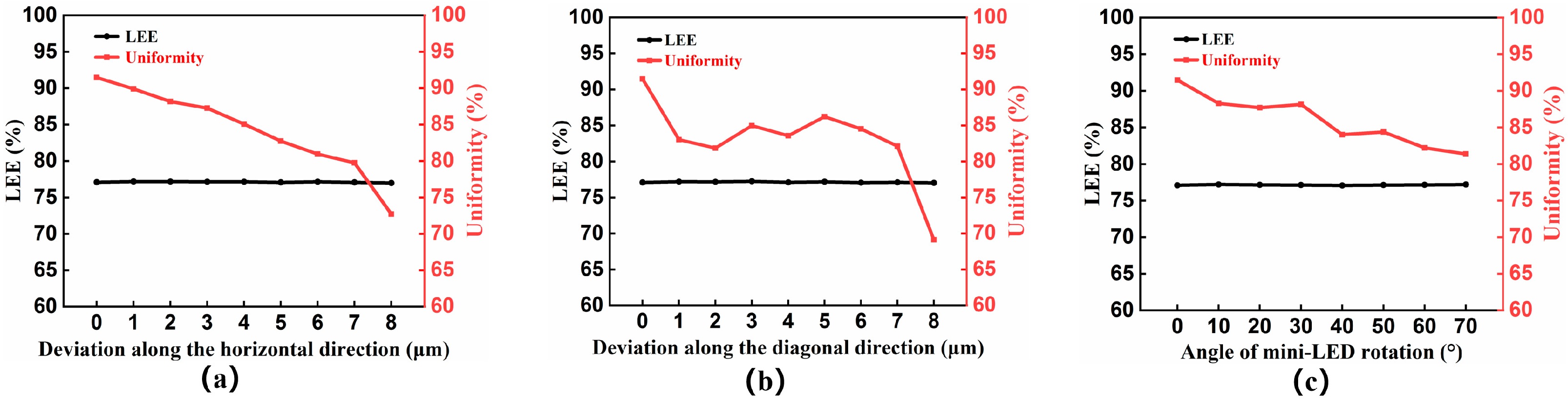
4.2. Tolerance Analysis

In this backlight structure, the light from the mini-LED is reflected by the cone-shaped light coupling microstructure and then enters the LGP, which expands the illumination area of the mini-LED and improves the illuminance uniformity. In a real light coupling microstructure, its “tip” has a non-zero diameter. Here, the influence of the non-zero “tip” on the optical performance is studied. Figure 7 shows the simulated LEE and uniformity of the backlight structure when the tip of the cone-shaped light coupling microstructure has different radiuses. As shown in Figure 7, the illuminance uniformity of the backlight structure changes very little when the radius of the tip increases from 0 to 7 μm with a size of 0.7 μm and all of them are larger than 85%. All the LEEs are stable at 77%. These results show that the backlight structure can provide high performance even when the tip of the cone-shaped light coupling microstructure has a limited non-zero radius.
In addition, the deviation of the mini-LED center off the cone-shaped light coupling microstructure also has an influence on the optical performance of the backlight structure including the illuminance uniformity and LEE. Three cases influence the optical performance, including when the center of the mini-LED deviates off the cone-shaped light coupling microstructure along the horizontal and diagonal directions, or when the mini-LED center rotates by different angles along the central axis.
As shown in Figure 8a, the uniformity of the backlight structure decreases as the deviation of the mini-LED center off the light coupling microstructure along the horizontal direction increases. The uniformity is less than 80% when the deviation distance exceeds 7 μm. This indicates that when the deviation distance along the horizontal direction is less than 7 μm, its influence on the uniformity of the backlight structure is within an allowable range. Similarly, it can be seen from Figure 8b that when the deviation of the mini-LED center off the light coupling microstructure along the diagonal direction exceeds 7 μm, the uniformity is less than 80%. In both cases, the LEE of the backlight structure with different deviation distances is around 77%, which indicates that these two deviations have little effect on the LEE. Figure 8c shows the relationship between the angle of mini-LED rotation and optical performance. As shown in Figure 8c, the uniformity decreases as the angle of mini-LED rotation increases. All the uniformities are larger than 80%, which indicates that the influence of mini-LED rotation on the uniformity is within an allowable range. In addition, all the LEEs are stable around 77%. These results show that as long as the deviations are controlled within a certain range, the uniformity and LEE of the backlight structure can remain at an allowable level.

4.3. Comparison between Different Light Coupling Microstructures

In addition to the cone-shaped light coupling microstructure discussed, we also simulate the single local dimming zone of light coupling microstructures with other shapes, including the circle shape, inverted triangle shape, and concave shape. Figure 9 shows the light coupling microstructures of different shapes.
In order to distinguish the differences of each light coupling microstructure more clearly, the cross-sectional profiles of each light coupling microstructure are shown in Figure 10. The light coupling microstructure is formed by rotating the cross-sectional profile 360° along the central axis. As shown in Figure 10, the red line in the coordinate system is the cross-sectional profile, and a and b are the length and height of the cross-sectional profile, respectively. It is clearly seen in Figure 10b that the length and height of the circle-shaped light coupling microstructure profile are both a. The point (a1, b1), point (a1, b2), point (a1, b3), point (a1, b4) are the points on the contour of the cone-shaped, circle-shaped, inverted triangular, and concave-shaped light coupling microstructure profiles respectively. The black oblique line is the tangent line of the cross-sectional profile of the light coupling microstructure. The tangent line equation is as follows:
y = k x + b ( k = k 1 , k 2 , k 3 , k 4 , c = c 1 , c 2 , c 3 , c 4 )
where k is the slope of the tangent line of each light coupling microstructure profile and c is the distance that the line y = kx moves along the y-axis.
Since the cross-sectional profile of the inverted triangular light coupling microstructure is a straight line, its tangent line is the profile itself. It can be seen from Figure 10 that the changing trends of the cross-sectional profiles are different for variously shaped light coupling microstructures. The slopes of the profiles of the cone-shaped light coupling microstructure and the circle-shaped light coupling microstructure decrease as x increases. However, the slope of the cone-shaped light coupling microstructure profile decreases faster. In contrast, the slope of the concave-shaped light coupling microstructure profile increases with x. The slope of cross-sectional profile of the inverted triangular light coupling microstructure remains constant because it is a straight line.
The corresponding LEE and illuminance uniformity of different light coupling microstructures are shown in Table 2. It can be seen that the LEE achieved by the cone-shaped light coupling microstructure proposed in this paper is comparable to that of the circle-shaped light coupling microstructure and the inverted triangular light coupling microstructure. The LEE of the concave-shaped light coupling microstructure is the lowest. The cone-shaped light coupling microstructure has the highest uniformity. This is mainly due to the different curvature variation patterns from the center to the edges of the different light coupling microstructures. The curvature change of the cone-shaped light coupling microstructure is smaller and smaller from the center to the edge, which matches the angle of the light from the mini-LED and the angle of light incident into the LGP. This allows more light to enter the LGP and then be fully internally reflected within the LGP. This also demonstrates the rationality of our proposed cone-shaped light coupling microstructure.

5. Conclusions

Combining the characteristics of direct-lit and edge-lit backlights, this paper proposes a new mini-LED backlight structure, which is a zero-optical-distance mini-LED backlight with cone-shaped light coupling microstructures. In this design, the mini-LED is embedded in the reflector to achieve “zero optical distance” between the LGP and the reflector, as well as the LGP and the mini-LED embedded in the reflector. The thickness of the mini-LED backlight is successfully reduced to ~ 0.1 mm, which is much thinner than conventional mini-LED backlights with diffuser plates. The light from the mini-LED enters the LGP through the cone-shaped light coupling microstructure and finally exits the LGP through the scattering dots to form a uniform surface light source. Simulation results show that this proposed backlight structure can not only reduce the thickness of the backlight module, but also achieve better LEE and illuminance uniformity. By adding a color conversion film on the upper surface of the LGP, the entire backlight structure can achieve good white balance. Nine single local dimming zones are spliced together to achieve 2D local dimming. The light crosstalk between adjacent local dimming zones is 0.29%, which realizes high 2D local dimming performance. This work is of great significance for realizing the thinning of the backlight module, and it can also improve the contrast ratio and image quality of LCDs through 2D local dimming. It is foreseeable that this mini-LED backlight structure could promote the development of LCDs.

Author Contributions

Conceptualization, methodology, writing—review, and editing, Z.L.; review and suggestions, H.J., D.Y. and W.Z.; conceptualization, funding acquisition, review, and editing, E.C.; review and funding acquisition, Y.Y., S.X., Q.Y. and T.G. All authors have read and agreed to the published version of the manuscript.

Funding

This research was funded by the National Natural Science Foundation of China (62175032); the Fujian Provincial Key Science and Technology Project (2021HZ021001); the Fujian Provincial Natural Science Foundation Project (2021J01579); and Fujian Science & Technology Innovation Laboratory for Optoelectronic Information of China (2020ZZ111).

Institutional Review Board Statement

Not applicable.

Informed Consent Statement

Not applicable.

Data Availability Statement

Not applicable.

Conflicts of Interest

There are no conflict of interest.

References

  1. Tan, G.; Zhu, R.; Tsai, Y.-S.; Lee, K.-C.; Luo, Z.; Lee, Y.-Z.; Wu, S.-T. High ambient contrast ratio OLED and QLED without a circular polarizer. J. Phys. D Appl. Phys. 2016, 49, 315101. [Google Scholar] [CrossRef]
  2. Yang, X.; Dev, K.; Wang, J.; Mutlugun, E.; Dang, C.; Zhao, Y.; Tan, S.T.; Sun, X.W.; Demir, H.V. Low-cost, large-scale, ordered ZnO nanopillar arrays for light extraction efficiency enhancement in quantum dot light-emitting diodes. In Proceedings of the 2014 IEEE Photonics Conference, San Diego, CA, USA, 12–16 October 2014; pp. 534–535. [Google Scholar]
  3. Putman, P.H. Display Technology: The Next Chapter. SMPTE Motion Imaging J. 2016, 125, 30–34. [Google Scholar] [CrossRef]
  4. Hu, X.; Cai, J.; Liu, Y.; Zhao, M.; Chen, E.; Sun, J.; Yan, Q.; Guo, T.J.O.; Technology, L. Design of inclined omni-directional reflector for sidewall-emission-free micro-scale light-emitting diodes. Optics Laser Technol. 2022, 154, 108335. [Google Scholar] [CrossRef]
  5. Chen, E.; Zhao, Y.; Lin, S.; Cai, J.; Xu, S.; Ye, Y.; Yan, Q.F.; Guo, T. Design of improved prototype of two-in-one polarization-interlaced stereoscopic projection display. Opt. Express 2019, 27, 4060–4076. [Google Scholar] [CrossRef]
  6. Cai, J.; Wang, C.; Hu, X.; Ye, Y.; Zhong, L.; Chen, E.; Ye, Y.; Xu, S.; Sun, J.; Yan, Q.; et al. Water-driven photoluminescence reversibility in CsPbBr3/PDMS-PUa composite. Nano Res. 2022, 15, 6466–6476. [Google Scholar] [CrossRef]
  7. Chen, E.; Lin, J.; Yang, T.; Chen, Y.; Zhang, X.; Ye, Y.; Sun, J.; Yan, Q.; Guo, T. Asymmetric Quantum-Dot Pixelation for Color-Converted White Balance. ACS Photonics 2021, 8, 2158–2165. [Google Scholar] [CrossRef]
  8. Chen, H.-W.; Lee, J.-H.; Lin, B.-Y.; Chen, S.; Wu, S.-T. Liquid crystal display and organic light-emitting diode display: Present status and future perspectives. Light Sci. Appl. 2018, 7, 17168. [Google Scholar] [CrossRef] [Green Version]
  9. Burini, N.; Nadernejad, E.; Korhonen, J.; Forchhammer, S.; Wu, X. Modeling Power-Constrained Optimal Backlight Dimming for Color Displays. J. Disp. Technol. 2013, 9, 656–665. [Google Scholar] [CrossRef] [Green Version]
  10. Chen, E.; Xie, H.; Huang, J.; Miu, H.; Shao, G.; Li, Y.; Guo, T.; Xu, S.; Ye, Y. Flexible/curved backlight module with quantum-dots microstructure array for liquid crystal displays. Opt. Express 2018, 26, 3466–3482. [Google Scholar] [CrossRef]
  11. Feng, X.; Sun, X.; Zhang, Q.; Yang, Z.; Liu, S.; Qiu, Y.; Wang, D. 21.1: Invited Paper: Development Trend of LCD Technology. Proc. SID Symp. Dig. Tech. Pap. 2018, 49, 207–211. [Google Scholar] [CrossRef]
  12. Leiner, C.; Nemitz, W.; Schweitzer, S.; Wenzl, F.; Kuna, L.; Reil, F.; Hartmann, P.; Sommer, C. Thin direct-lit application for general lighting realized by freeform micro-optical elements. Proc. Proc. SPIE 2016, 9955, 99550E. [Google Scholar]
  13. Ding, Z.; Liu, Y.; Ma, Y.; Zheng, Z.; Wang, M.; Zeng, P.; She, J.; Wu, R. Direct Design of Thin and High-Quality Direct-Lit LED Backlight Systems. IEEE Photonics J. 2021, 13, 1–10. [Google Scholar] [CrossRef]
  14. Huang, C.-H.; Kang, C.-Y.; Chang, S.-H.; Lin, C.-H.; Lin, C.-Y.; Wu, T.; Sher, C.-W.; Lin, C.-C.; Lee, P.-T.; Kuo, H.-C. Ultra-High Light Extraction Efficiency and Ultra-Thin Mini-LED Solution by Freeform Surface Chip Scale Package Array. Crystals 2019, 9, 202. [Google Scholar] [CrossRef] [Green Version]
  15. Park, Y.-M.; Bang, H.-C.; Seo, Y.-H.; Kim, B.-H. Development of surface-mount-type crown-shaped lens for reducing glare effect of light-emitting diode light source. J. Korean Soc. Manuf. Technol. Eng. 2014, 23, 64–68. [Google Scholar]
  16. Masuda, J.; Takase, K.; Yamaguchi, N.; Miyata, H. 28-1: Ultra-slim Backlight with High Luminance Using Multiple Advanced Light Guide Plate Technology. SID Symp. Dig. Tech. Pap. 2019, 50, 382–385. [Google Scholar] [CrossRef]
  17. Yoon, G.-W.; Bae, S.-W.; Lee, Y.-B.; Yoon, J.-B. Edge-lit LCD backlight unit for 2D local dimming. Opt. Express 2018, 26, 20802–20812. [Google Scholar] [CrossRef]
  18. Chen, E.; Lin, S.; Jiang, Z.; Guo, Q.; Xu, S.; Ye, Y.; Yan, Q.F.; Guo, T. Analytic design of light extraction array for light guide plate based on extended sources. Opt. Express 2019, 27, 34907–34920. [Google Scholar] [CrossRef]
  19. Jiang, Z.; Ye, Y.; Guo, J.; Pan, J.; Cao, X.; Guo, T.; Chen, E. Optimal dimension of edge-lit light guide plate based on light conduction analysis. Opt. Express 2021, 29, 18705–18719. [Google Scholar] [CrossRef] [PubMed]
  20. Huang, Y.; Hsiang, E.-L.; Deng, M.-Y.; Wu, S.-T. Mini-LED, Micro-LED and OLED displays: Present status and future perspectives. Light: Sci. Appl. 2020, 9, 105. [Google Scholar] [CrossRef]
  21. Wu, T.; Sher, C.-W.; Lin, Y.; Lee, C.-F.; Liang, S.; Lu, Y.; Huang Chen, S.-W.; Guo, W.; Kuo, H.-C.; Chen, Z. Mini-LED and Micro-LED: Promising Candidates for the Next Generation Display Technology. Appl. Sci. 2018, 8, 1557. [Google Scholar] [CrossRef] [Green Version]
  22. Hulze, H.G.; deGreef, P. 50.2: Power savings by local dimming on a LCD panel with side lit backlight. Proc. SID Symp. Dig. Tech. Pap. 2009, 40, 749–752. [Google Scholar] [CrossRef]
  23. Tan, G.; Huang, Y.; Li, M.-C.; Lee, S.-L.; Wu, S.-T. High dynamic range liquid crystal displays with a mini-LED backlight. Opt. Express 2018, 26, 16572–16584. [Google Scholar] [CrossRef] [PubMed]
  24. Chen, H.; Tan, G.; Wu, S.-T. Ambient contrast ratio of LCDs and OLED displays. Opt. Express 2017, 25, 33643–33656. [Google Scholar] [CrossRef] [Green Version]
  25. Ye, Z.T.; Cheng, Y.H.; Liu, K.H.; Yang, K.S. Mini-LEDs with Diffuse Reflection Cavity Arrays and Quantum Dot Film for Thin, Large-Area, High-Luminance Flat Light Source. Nanomaterials 2021, 11, 2395. [Google Scholar] [CrossRef] [PubMed]
  26. Li, F.; Zong, Z.; Zhang, N.; Mu, L.; Liu, X. 12.3: Research on Reducing H: P Value of Lensless Direct-lit Backlight Module. SID Symp. Dig. Tech. Pap. 2021, 52, 180–182. [Google Scholar] [CrossRef]
  27. Chang, K.; Yu, L.; Sang, J. P-5.13: Visual Luminance Uniformity and OD value calculation for Direct Type Mini-LED Backlight. SID Symp. Dig. Tech. Pap. 2019, 50, 750–752. [Google Scholar] [CrossRef]
  28. Chen, Y.-L.; Chin, W.-C.; Tsai, C.-W.; Chiu, C.-C.; Tien, C.-H.; Ye, Z.-T.; Han, P. Wide-Angle Mini-Light-Emitting Diodes without Optical Lens for an Ultrathin Flexible Light Source. Micromachines 2022, 13, 1326. [Google Scholar] [CrossRef]
  29. Masuda, T.; Watanabe, H.; Kyoukane, Y.; Yasunaga, H.; Miyata, H.; Yashiki, M.; Nara, T.; Ishida, T. 28-3: Mini-LED Backlight for HDR Compatible Mobile Displays. Proc. SID Symp. Dig. Tech. Pap. 2019, 50, 390–393. [Google Scholar] [CrossRef]
  30. Deng, Z.; Zheng, B.; Zheng, J.; Wu, L.; Yang, W.; Lin, Z.; Shen, P.; Li, J. 74-5: Late-News Paper: High Dynamic Range Incell LCD with Excellent Performance. SID Symp. Dig. Tech. Pap. 2018, 49, 996–998. [Google Scholar] [CrossRef]
  31. Chen, H.; Ha, T.H.; Sung, J.H.; Kim, H.R.; Han, B.H. Evaluation of LCD local-dimming-backlight system. J. Soc. Inf. Disp. 2010, 18, 57–65. [Google Scholar] [CrossRef]
  32. Huang, Y.; Tan, G.; Gou, F.; Li, M.-C.; Lee, S.-L.; Wu, S.-T. Prospects and challenges of mini-LED and micro-LED displays. J. Soc. Inf. Disp. 2019, 27, 387–401. [Google Scholar] [CrossRef]
  33. Gao, Z.; Ning, H.; Yao, R.; Xu, W.; Zou, W.; Guo, C.; Luo, D.; Xu, H.; Xiao, J. Mini-LED Backlight Technology Progress for Liquid Crystal Display. Crystals 2022, 12, 313. [Google Scholar] [CrossRef]
  34. Chen, E.; Guo, J.; Jiang, Z.; Shen, Q.; Ye, Y.; Xu, S.; Sun, J.; Yan, Q.; Guo, T. Edge/direct-lit hybrid mini-LED backlight with U-grooved light guiding plates for local dimming. Opt. Express 2021, 29, 12179–12194. [Google Scholar] [CrossRef] [PubMed]
  35. Kikuchi, S.; Shibata, Y.; Ishinabe, T.; Fujikake, H. Thin mini-LED backlight using reflective mirror dots with high luminance uniformity for mobile LCDs. Opt. Express 2021, 29, 26724–26735. [Google Scholar] [CrossRef] [PubMed]
  36. Teng, T.-C.; Kuo, M.-F. Optical characteristic of the light guide plate with microstructures engraved by laser. Proc. Proc. SPIE 2012, 8485, 201–208. [Google Scholar]
  37. Chung, C.-K.; Sher, K.-L.; Syu, Y.-J.; Cheng, C.-C. Fabrication of cone-like microstructure using UV LIGA-like for light guide plate application. Microsyst. Technol. 2010, 26, 1619–1624. [Google Scholar] [CrossRef]
  38. Yi, P.; Wu, H.; Zhang, C.; Peng, L.; Lai, X. Roll-to-roll UV imprinting lithography for micro/nanostructures. J. Vac. Sci. Technol. B Nanotechnol. Microelectron. Mater. Process. Meas. Phenom. 2015, 33, 060801. [Google Scholar] [CrossRef]
  39. Kim, S.-W.; Kim, H.-G.; Lee, S.-E.; Lee, H.; Lee, H.-C. Fabrication of Film-Type Light Guide Plates by Using UV Nano-Imprint Lithography to Enhance Optical Properties. Nanosci. Nanotechnol. Lett. 2016, 8, 13–20. [Google Scholar] [CrossRef]
  40. Fan, F.-Y.; Chou, H.-H.; Lin, W.-C.; Huang, C.-F.; Lin, Y.; Shen, Y.-K.; Ruslin, M. Optimized micro-pattern design and fabrication of a light guide plate using micro-injection molding. Polymers 2021, 13, 4244. [Google Scholar] [CrossRef] [PubMed]
  41. Zeng, X.-Y.; Yang, L.; Zhou, X.-T.; Zhang, Y.-A.; Chen, E.-G.; Guo, T.-L. Pixel arrangement optimization of two-dimensional light-emitting diode panel for low-crosstalk autostereoscopic light-emitting diode displays. Opt. Eng. 2017, 56, 063104. [Google Scholar] [CrossRef]
  42. Zeng, X.-Y.; Zhou, X.-T.; Guo, T.-L.; Yang, L.; Chen, E.-G.; Zhang, Y.-A. Crosstalk reduction in large-scale autostereoscopic 3D-LED display based on black-stripe occupation ratio. Opt. Commun. 2017, 389, 159–164. [Google Scholar] [CrossRef] [Green Version]
  43. Xu, S.; Yang, T.; Lin, J.; Shen, Q.; Li, J.; Ye, Y.; Wang, L.; Zhou, X.; Chen, E.; Ye, Y.; et al. Precise theoretical model for quantum-dot color conversion. Opt. Express 2021, 29, 18654–18668. [Google Scholar] [CrossRef] [PubMed]
Figure 1. Schematic of (a) a zero-optical-distance mini-LED backlight with cone-shaped light coupling microstructures, (b) a mini-LED backlight module with nine local dimming zones, and (c) a single local dimming zone.
Crystals 13 00241 g001
Figure 2. Schematic of the light propagation in the LGP.
Crystals 13 00241 g002
Figure 3. Simulation results of a single local dimming zone: (a) 2D irradiance map and (b) normalized irradiance distribution curves in the horizontal and vertical direction.
Crystals 13 00241 g003
Figure 4. Simulation results of the zero-optical-distance mini-LED backlight: (a) 2D irradiance map and (c) the corresponding irradiance distribution curves when the nine local dimming zones are working at the same time; (b) 2D irradiance map and (d) the corresponding irradiance distribution curves when only the central local dimming zone is active.
Crystals 13 00241 g004
Figure 5. (a) Schematic of the zero-optical-distance mini-LED backlight for white balance; (b) Simulated color coordinates of the nine points in CIE 1931 color space; (c) 2D irradiance map; (d) A true color map.
Crystals 13 00241 g005
Figure 6. Relationships between the thickness of the LGP and the LEE and uniformity.
Crystals 13 00241 g006
Figure 7. Relationships between the “tip” radius of the cone-shaped light coupling microstructure and the LEE and uniformity.
Crystals 13 00241 g007
Figure 8. Relationships between the different deviations of the mini-LED center off the cone-shaped light coupling microstructure and the LEE and uniformity: (a) Deviation along the horizontal direction, (b) deviation along the diagonal direction, and (c) mini-LED rotation.
Crystals 13 00241 g008
Figure 9. Schematic of different light coupling structures: (a) cone shape, (b) circle shape, (c) inverted triangle shape, (d) concave shape.
Crystals 13 00241 g009
Figure 10. Schematic of cross-sectional profiles of different light coupling structures: (a) cone shape, (b) circle shape, (c) inverted triangle shape, (d) concave shape.
Crystals 13 00241 g010
Table 1. CIE 1931 color coordinates of the nine points.
Coordinate Position (x, y)CIE 1931 Color Coordinate (x, y)
(0.6, 0.6)(0.2931, 0.3278)
(0.6, 0.0)(0.3071, 0.3497)
(0.6, −0.6)(0.2886, 0.3188)
(0.0, 0.6)(0.3063, 0.3491)
(0.0, 0.0)(0.3068, 0.3509)
(0.0, −0.6)(0.3085, 0.3546)
(−0.6, 0.6)(0.2925, 0.3249)
(−0.6, 0.0)(0.3088, 0.3535)
(−0.6, −0.6)(0.2968, 0.3382)
Table 2. Comparison of the LEE and spatial illuminance uniformity for different light coupling microstructures.
TypeLEEUniformity
Cone shape77.09%91.47%
Circle shape80.62%81.61%
Inverted triangle shape77.23%88.07%
Concave shape69.62%85.8%
Disclaimer/Publisher’s Note: The statements, opinions and data contained in all publications are solely those of the individual author(s) and contributor(s) and not of MDPI and/or the editor(s). MDPI and/or the editor(s) disclaim responsibility for any injury to people or property resulting from any ideas, methods, instructions or products referred to in the content.

