Article

Powder Fabrication and Laser Powder Bed Fusion of a MoSiBTiC-La2O3 Alloy

Department of Material Processing, Graduate School of Engineering, Tohoku University, Sendai 980-8579, Miyagi, Japan
*
Authors to whom correspondence should be addressed.
Crystals 2023, 13(2), 215; https://doi.org/10.3390/cryst13020215
Submission received: 31 December 2022 / Revised: 20 January 2023 / Accepted: 21 January 2023 / Published: 24 January 2023
(This article belongs to the Special Issue Advances in Metal Matrix Composites)

Abstract

:
In the present work, an approach of freeze-dry pulsated orifice ejection method (FD-POEM) was utilized to fabricate monodispersed MoSiBTiC-La2O3 composite powders for laser powder bed fusion (L-PBF). The FD-POEM powders were spherically shaped, possessing a narrow size range and uniform element distribution. As revealed by the single-track and single-layer experiments, the porous FD-POEM particles were sufficiently fused under laser irradiation, leading to the generation of continuous laser tracks and low surface roughness layers, which proved a feasible L-PBF processability of MoSiBTiC-La2O3 powders. Careful microstructural observations confirmed that the microstructure of the molten pools was primarily composed of Mo solid solution dendrites reinforced with La2O3 nanoparticles. Consequently, the single MoSiBTiC-La2O3 track had a high Martens hardness of 3955 HM. The result of this work reveals that the combination of FD-POEM and L-PBF has a great potential of developing advanced heat-resistant Mo-based alloys with tailored structures for ultrahigh-temperature applications.

1. Introduction

With the development of the aerospace industries, the working temperature of traditional alloys has difficulty meeting the demands of the efficiency of gas-turbine engines operating at higher temperatures [1]. The design of new-generation high-temperature materials with higher operating temperatures than Ni-based superalloys is imminent [2]. The Mo-Si-B alloys are regarded as a promising candidate for the ultrahigh-temperature applications because of their high melting point and excellent high-temperature creep strength [3,4,5]. Yoshimi et al. [6] recently proposed a TiC-added Mo-Si-B alloy, namely, a MoSiBTiC alloy with the composition of 65Mo-5Si-10B-10Ti-10C (at.%). The MoSiBTiC alloy has a great application potential because of its superior creep strength at ultrahigh temperatures, lower density compared to Ni-based superalloys, and high room-temperature fracture toughness [7,8]. However, the poor oxidation resistance of MoSiBTiC alloys limits their further applications in the aerospace field [4,9]. Furthermore, the traditional processing routes such as casting and powder metallurgy [5] are not suitable for complex structures.
The fabrication of an oxide dispersion strengthening (ODS) alloy is considered to be a promising option to improve the oxidation resistance of MoSiBTiC alloys [10,11,12,13,14]. The oxide dispersions can prevent the penetration rate of oxygen atoms and benefit from the spallation resistance of oxide scales formed on the alloys [10]. The addition of elemental lanthanum into the Titanium–Zirconium–Molybdenum (TZM) alloy was reported to form tiny lanthanum oxide particles. Those oxides could effectively block the invasion of oxygen to the matrix and, thus, improve the oxidation resistance of the La-TZM alloy [11]. Jéhanno et al. [12] found that Mo-3Si-1B alloy with 0.1 wt.% La2O3 showed an improved oxidation resistance at 820 °C and 1300 °C. Burk et al. [13] studied the oxidation behavior of Mo-9Si-8B-La2O3 alloys at different temperatures. The oxygen diffusion through the silica scale of Mo-9Si-8B alloy can be drastically reduced by the addition of La2O3. Majumdar et al. [14] reported that La-doping was effective in improving the oxidation resistance of the Mo-9Si-8B alloy at higher temperatures >900 °C. The element La diffused outwards and segregated at the metal/oxide interface to form La-oxide. However, the study of ODS on the microstructure and oxidation behavior of Mo-Si-B alloys is limited to traditional manufacturing processes.
Laser powder bed fusion (L-PBF) is one typical technology of the additive manufacturing (AM) processes that use a laser beam to selectively melt a preplaced powder and build up the parts layer by layer [15,16,17]. Compared with conventional methods, the L-PBF process can directly manufacture components with complex shapes or structures without molds. Conventional alloys, such as steel [18] or titanium [19], have proven to be processed successfully with AM. For instance, Zhou et al. [20] fabricated a novel ceramic layer-coated 316L stainless steel alloy with L-PBF using severely oxidized powders. The mechanical strength of this alloy was found to be similar to that processed using the virgin powders. L-PBF is a promising technique for preparing complex-shaped ODS alloy parts.
The feedstock AM powders with excellent properties (e.g., spherical shape, good flowability or suitable particle size distribution) are in demand to make high-quality L-PBF parts. In this work, the uniform distribution of oxide nanoparticles in the MoSiBTiC alloy powders is critical to form high-performance ODS alloys by L-PBF. Generally, the AM powders are mainly fabricated by the manufacturing approaches of several kinds of atomization such as gas or plasma atomization, rotating electrode process, and so on [21]. However, these techniques have limitations in fabricating oxides/alloy composite powders [22,23,24]. It is challenging to fabricate uniform composite powders by the atomization technology due to their differences in density and melting points between the incorporated oxides and the alloy matrix [24]. Therefore, a new approach of fabricating AM composite powders is needed.
Taking La2O3 as one of typical oxide nanoparticles, in this work, a technology of freeze-dry pulsated orifice ejection method (FD-POEM) was thus put forward to fabricate ODS composite powders for AM. Guo et al. [25] and Zhou et al. [26] have used the FD-POEM technique for the successful fabrication of pure molybdenum and MoSiBTiC alloy powders with a narrow size distribution and a uniform dispersion of component elements. Their results demonstrated the great processability of the FD-POEM technique in manufacturing refractory alloy powders. In this study, elemental Mo, MoB, Si, TiC, and La2O3 powders were dispersed in water to prepare a uniform slurry, which was subsequently extruded from an orifice into liquid nitrogen. Spherical MoSiBTiC-La2O3 powders were subsequently fabricated after a freeze-drying process. The powder characteristics and the L-PBF processability of the FD-POEM powders, as well as the microstructure of single MoSiBTiC-La2O3 layers, were systematically illustrated. This study may provide a new thought for fabricating ODS alloys using the combination of powder design and L-PBF techniques.

2. Experimental Section

2.1. Fabrication of MoSiBTiC-La2O3 Powders by FD-POEM

Mo, TiC (A.L.M.T Co., Ltd., Tokyo, Japan), MoB (Japan New Metals Co., Ltd., Osaka, Japan), Si (Tokyo Printing & Equipment Trading Co., Ltd., Tokyo, Japan), and La2O3 (EMJAPAN Co., Ltd., Tokyo, Japan) powders were used as the raw material powders. They were weighed according to the nominal composition of the 65Mo-5Si-10B-10Ti-10C (at.%) alloy, whose volume occupies 95% of the total volume of FD-POEM MoSiBTiC-La2O3 powder. The detailed FD-POEM process was performed as follows. The elemental powders were, first, blended in deionized water using mechanical and ultrasonic stirring for more than 1 h at 273 K to form a uniform slurry with a concentration of 5vol%. Subsequently, the slurry was provided to the FD-POEM apparatus. The working procedures and principle of the FD-POEM were interpreted in our previous works [27,28]. The diameter of the orifice nozzle was 100 μm. Finally, the monodispersed spherical MoSiBTiC-5vol% La2O3 particles were obtained via complete freeze-drying for more than 24 h. For comparison, a MoSiBTiC powder was also fabricated by using the same FD-POEM parameters.

2.2. Single-Track and Single-Layer Experiments of MoSiBTiC-La2O3 Powders via L-PBF

The laser melting tests of the FD-POEM MoSiBTiC-La2O3 powders were performed on Ti substrates using L-PBF. An inhouse L-PBF device using a Yb: YAG fiber laser with a wavelength of 1070 nm and a maximum power of 22 W (Raycus Fiber Laser Technology Co., Ltd., Wuhan, China) was used in this work [29]. The laser has a basic transverse Gaussian mode (TEM00) and a spot diameter of 45 μm. A cylindrical Ti substrate with a diameter ~10 mm was sandblasted and fixed onto the building platform. The whole process was carried out under an Ar gas atmosphere to prevent oxidation behaviors. The L-PBF parameters used for single-track and single-layer experiments are shown in Table 1.

2.3. Characterizations

The zeta potential of the La2O3 slurry was tested using a nanoparticle analyzer (SZ-100, HORIBA, Ltd., Kyoto, Japan). The particle size and distributions of FD-POEM particles were determined using an optical microscope (OM) (BX51, Olympus Corp., Tokyo, Japan) equipped with image analysis software (WinROOF, MITANI Corp., Tokyo, Japan). The microstructure of the FD-POEM particles and single-track specimens was evaluated using a scanning electron microscope (SEM) (JSM-6010LV, JEOL, Tokyo, Japan) with an energy-dispersive spectrometer (EDS) under an accelerating voltage of 15 kV and a field-emission SEM (FESEM; JSM-6500F, JEOL, Tokyo, Japan) under an accelerating voltage of 15 kV. The surface roughness was measured by using a 3D laser scanning microscope (VK-X200 series, Keyence Corp., Itasca, IL, USA). The phase composition of the powders was confirmed through X-ray diffraction (XRD, SmartLab, Rigaku Corp., Tokyo, Japan) using a 9 kW diffractometer with Cu Kα radiation at 45 kV and 200 mA. The mechanical properties of the polished molten pools were evaluated by using a micron-zone hardness testing machine (MZT-500, Mitutoyo Corp., Kawasaki, Japan).

3. Results and Discussion

Figure 1 shows the morphology of the raw powders used in this work. The Mo and TiC powders exhibited a polyhedral shape. The Si powders were lamellar shaped. The MoB and La2O3 powders exhibited an irregular shape. The medium particle sizes, d50, of the La2O3, Mo, MoB, Si, and TiC powders were determined to be ~0.5, 1.0, 4.3, 0.57, and 0.67 μm, respectively. In addition, the zeta potential of La2O3 in deionized water was measured to be +7.8 mV, while the zeta potential values of Mo, Si, MoB, and TiC powders were smaller than −40 mV. It is well-established that when the absolute value of the zeta potential exceeds 30 mV, the particle suspension is in a stable state. However, a stable homogeneous MoSiBTiC-La2O3 mixed slurry can still be obtained in the present study.
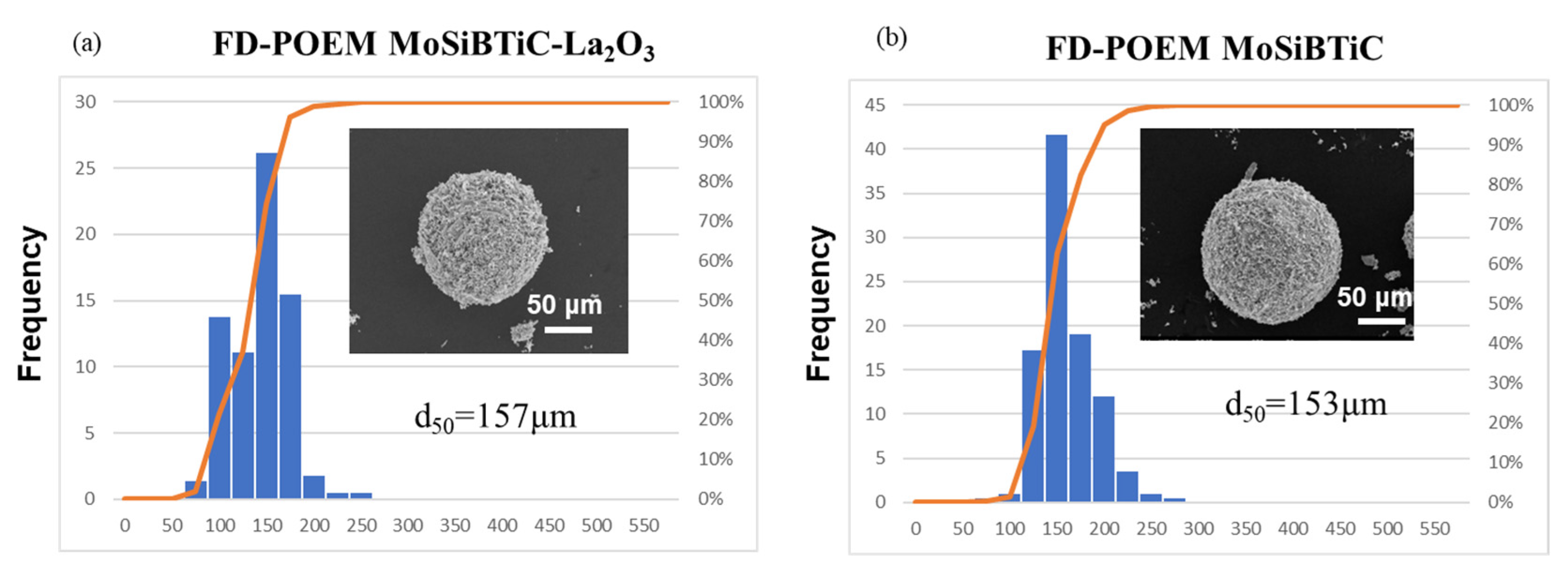
Figure 2 shows the particle size distributions of the MoSiBTiC-La2O3 and MoSiBTiC powders fabricated using the FD-POEM. The particle sizes of both powders were distributed in a range of 50–250 μm. The d50 of the MoSiBTiC-La2O3 or MoSiBTiC powders were determined to be approximately 157 and 153 µm, respectively. Insets in Figure 2 present the morphology of a typical MoSiBTiC-La2O3 or MoSiBTiC particle by SEM observations, respectively. The two kinds of powders exhibited a similarly spherical shape. The result indicates that the addition of La2O3 particles had an insignificant effect on the particle size and distribution of the FD-POEM powders, possibly attributing to the good dispersion and the nanodimension of the used La2O3 particles (~200 nm).
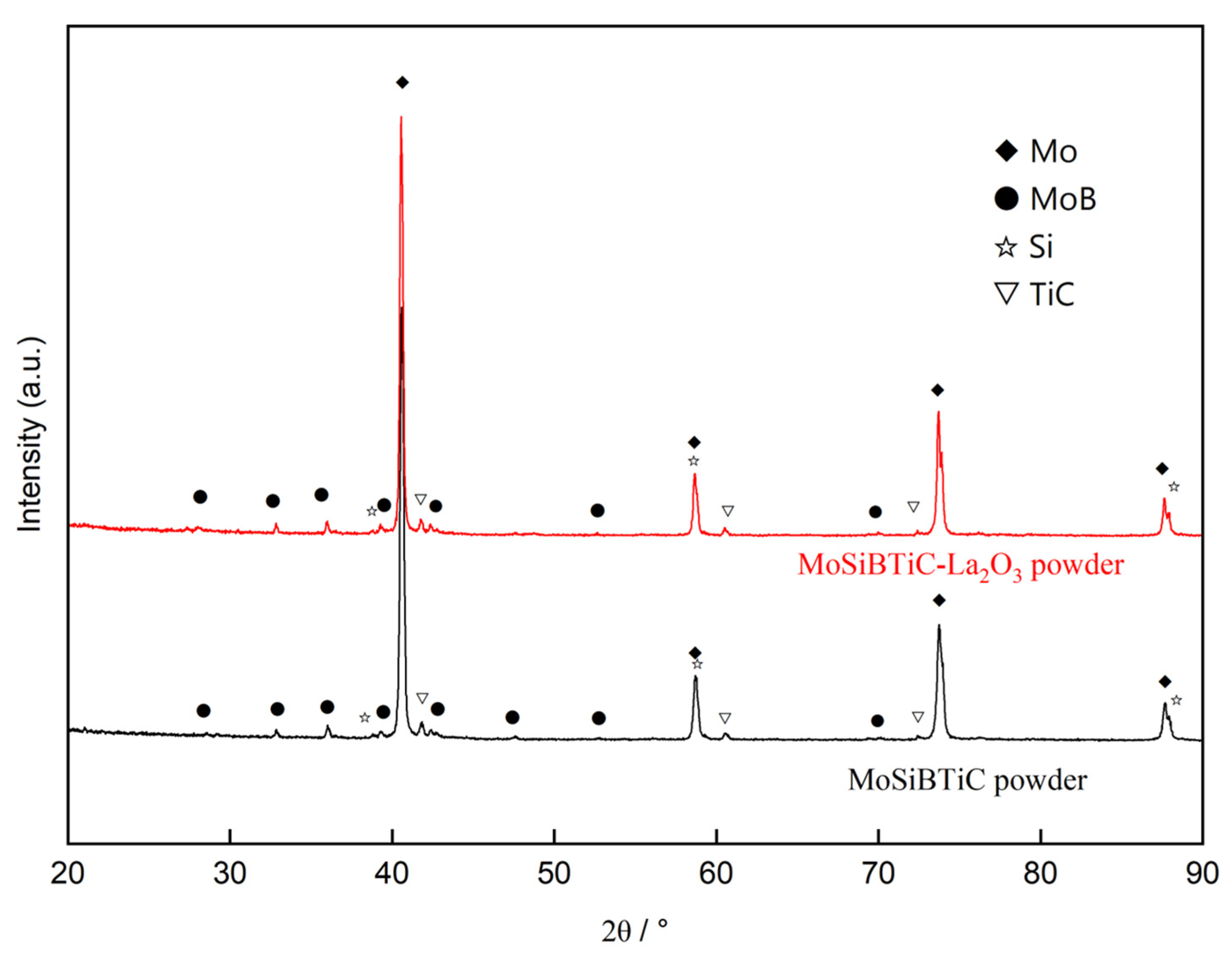
The XRD patterns of MoSiBTiC-La2O3 and MoSiBTiC powders are displayed in Figure 3. Both powders consisted of Mo, MoB, Si, and TiC phases, corresponding to the raw elemental particles. However, the diffraction peaks of La2O3 in the FD-POEM MoSiBTiC-La2O3 powders were not detected. This is possibly due to the low content and the uniform dispersion of the La2O3 nanoparticles.
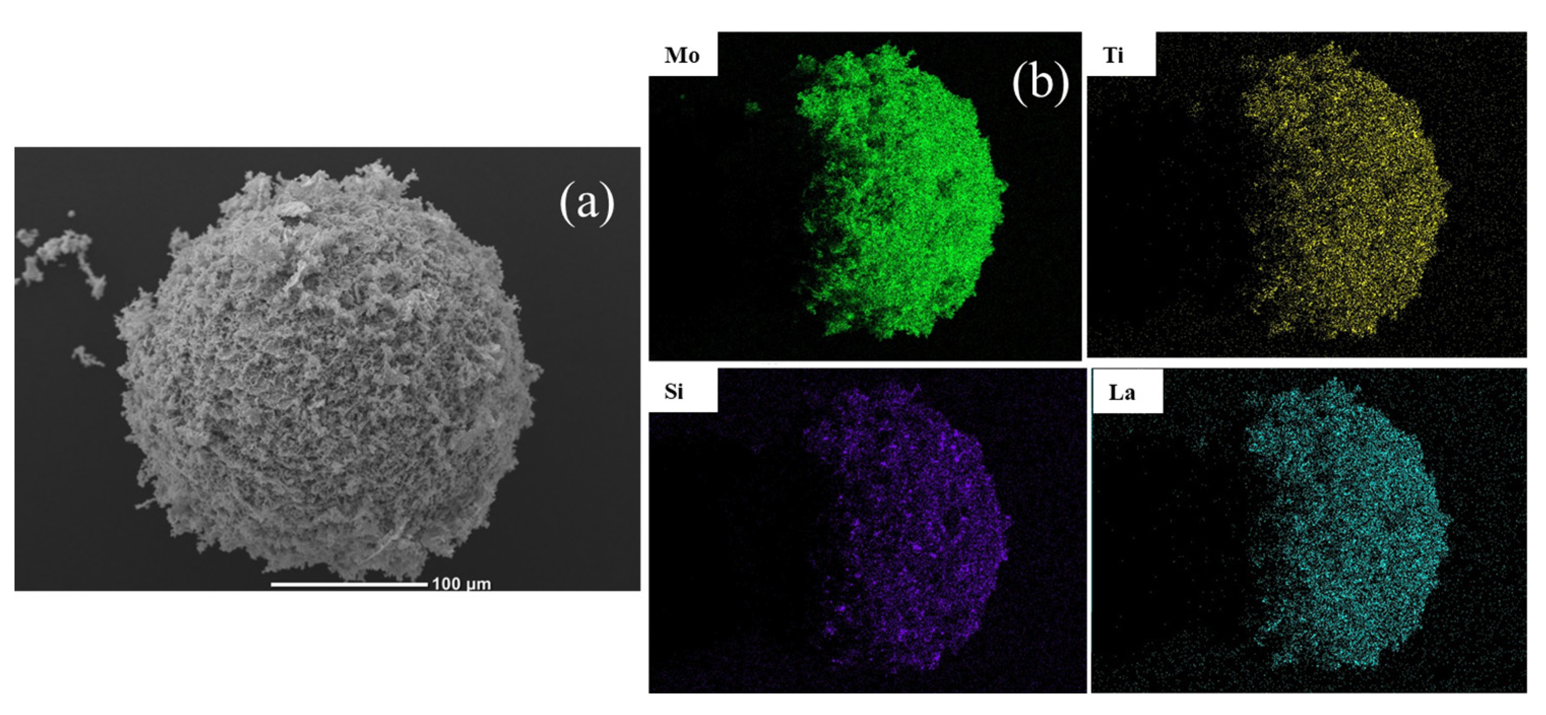
The SEM image and EDS mappings of a MoSiBTiC-La2O3 particle are displayed in Figure 4. Typical mesh-like pores were observed on the particle surface. This unique structure was caused by the solidification of the slurry and sublimation of ice crystals during the freeze-drying process [28]. As confirmed by the SEM-EDS mappings (see Figure 4b), elemental Mo, Si, Ti, and La were evenly distributed within the MoSiBTiC-La2O3 particle, owing to the uniform dispersion of elemental powders in the slurry mixture.
For the popularly used ball-milling process, the oxide nanoparticles were generally distributed on the surface of MoSiBTiC powders, giving rise to a nonuniform dispersion in a micron-sized view. Thus, the surface oxides possibly cause the lack of fusion of the metallic powders under laser irradiation. Moreover, the segregation of oxide phases may occur within the final ODS builds. Comparatively, the above issues are expected to be effectively avoided for the L-PBF processing of uniform FD-POEM MoSiBTiC-La2O3 powders.
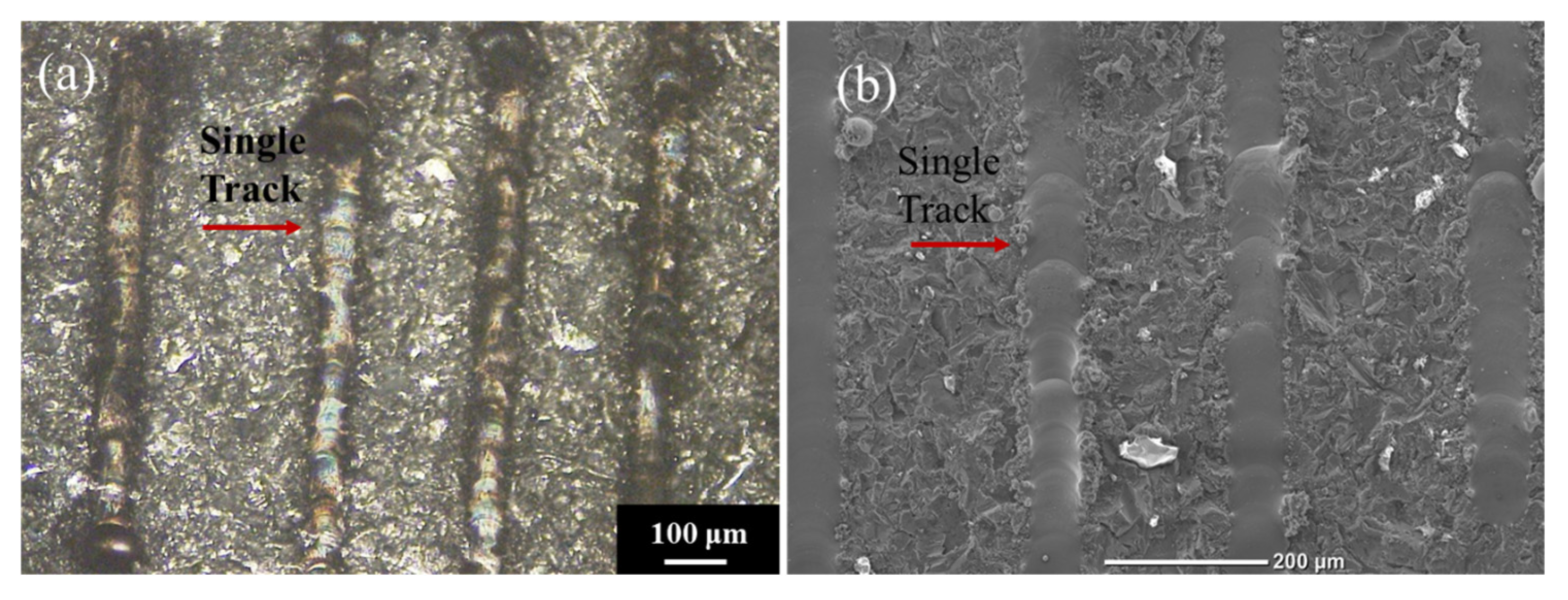
The research of molten pool geometry and microstructure of single-tracks is important to understand powder–laser interactions prior to the L-PBF process. Herein, the AM feasibility of FD-POEM powders was first checked by single-track experiments. The MoSiBTiC-La2O3 powders were fused when a laser beam traveled a long line, during which a single solid track was formed. As shown in Figure 5, due to the good flowability of the spherical FD-POEM particles, continuous single-tracks were formed on the Ti substrate. The average width of the single-track was determined to be 70 µm.
In addition, unmelted particles were not found in the laser tracks, proving that the L-PBF processing of FD-POEM MoSiBTiC-La2O3 powder is feasible. In general, high laser powers are required for processing refractory intermetallic or ceramic materials during L-PBF. However, the MoSiBTiC-La2O3 powders could be sufficiently melted even using a low laser power of 20.6 W in this work. This is likely attributed to the higher laser absorptivity of FD-POEM powders and the porose architecture consisting of elemental nanoparticles [26].
Single-layer experiments with different hatch distances (HDs) were also carried out.
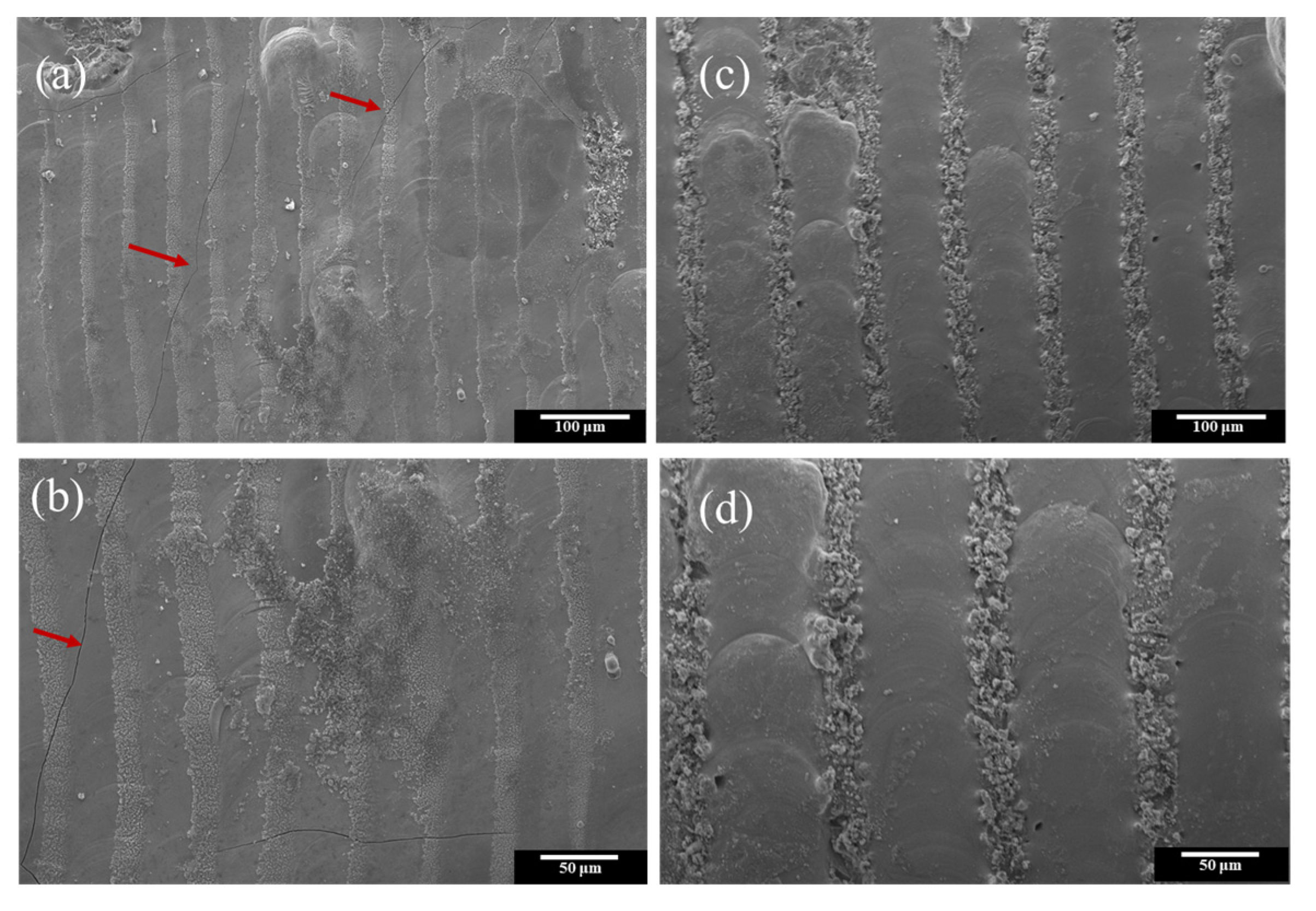
Figure 5 shows the SEM images of a single MoSiBTiC-La2O3 layer with 100 µm and 50 µm HDs. When the HD was 100 µm, two adjacent trackers were not connected due to the small width of the laser track: ~70 μm (Figure 5). In contrast, when the HD was decreased to 50 µm, two adjacent trackers were overlapped. Lack of fusion phenomenon was not observed on the layer surface. However, due to the intrinsically brittle nature of intermetallics and the rapid solidification rate of the L-PBF process (105–107 K/s) [30], some thermal cracks (see red arrows in Figure 6a) were detected in the single-layer.
Figure 7 shows the 3D surface morphology of a single MoSiBTiC-La2O3 layer with 50 µm HD. The surface roughness, Ra, was determined to be 2.6 μm. This low roughness is primarily due to the good flowability of spherical FD-POEM powders. Increasing powder flowability is expected to improve homogeneity in the powder beds, contributing to the quality of final L-PBF builds.
Figure 8 presents the cross-sectional morphology of polished single MoSiBTiC-La2O3 layers with 50 µm HD. The molten pools with a uniform size were clearly detected. The width and depth of the molten pools were measured to be 62 µm and 17 µm, respectively. Two adjacent molten pools were well-connected with an overlap ratio of 19%, agreeing with the surface observations in Figure 8a. The overlap ratio is one of the important building parameters during AM. Since the HD mainly determines the overlap rate between adjacent tracks, it will be further optimized for achieving high-quality L-PBF builds in near future [31,32].
The microstructure evolution of the FD-POEM MoSiBTiC-La2O3 powder during laser irradiation was illustrated by carefully monitoring a molten pool. Figure 9b,c shows the high-magnification SEM image and EDS mappings of a molten pool taken from the white square of Figure 9a. The microstructure of the molten pool is composed of dendritic structures, which possess fine secondary and tertiary dendrite arms (Figure 9b). According to the previous results in Ref. [33], the dendritic structures were corresponding to the Mo solid solution (Moss) phase. Due to the rapid solidification of the L-PBF process, the elemental Mo, Ti, or Si were dissolved in the Mo matrix for the formation of fine Moss structures. More importantly, as confirmed by the corresponding EDS mappings in Figure 9c, the La element was homogeneously distributed within the molten pool without apparent segregations. This result suggests the feasibility of fabricating MoSiBTiC alloys reinforced with uniformly dispersed La2O3 nanoparticles with L-PBF. The detailed microstructure of ODS MoSiBTiC alloy builds will be further investigated by TEM observation.
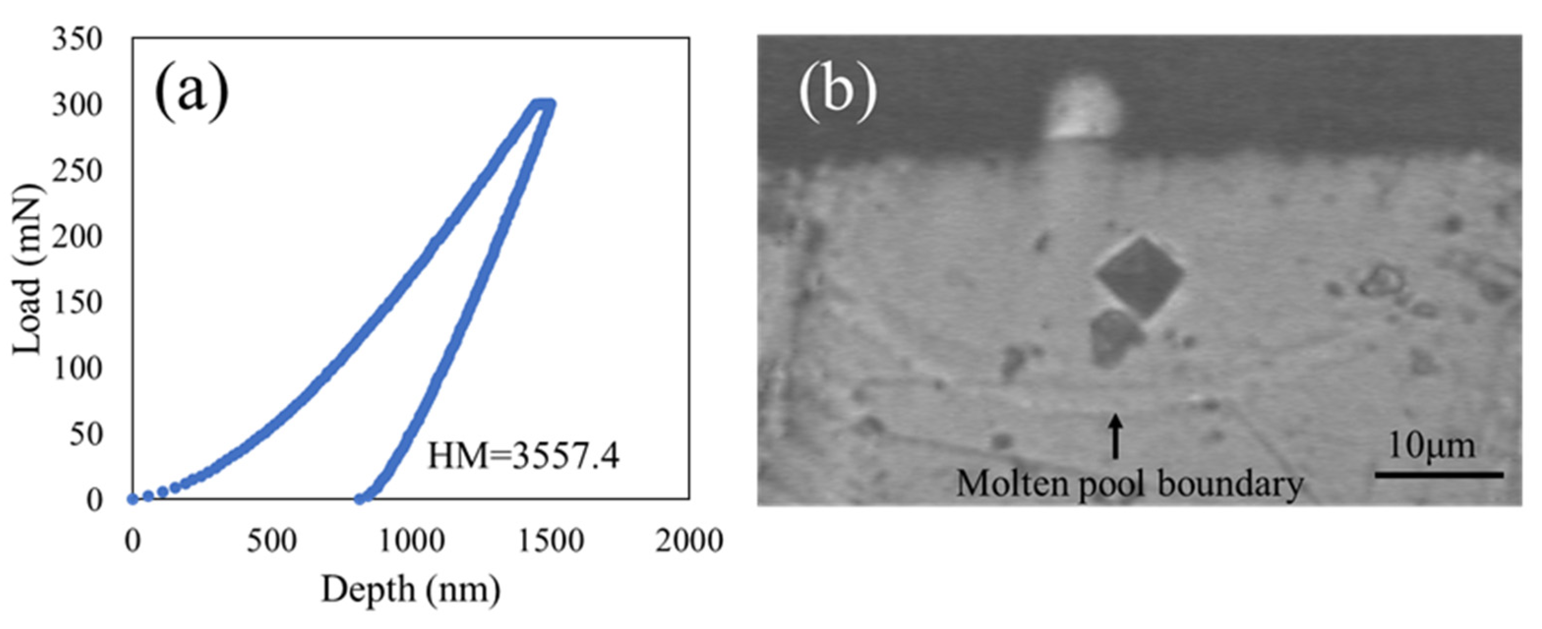
The mechanical property of a single MoSiBTiC-La2O3 track was evaluated by indentation tests. Figure 10a shows the typical indentation load–penetration depth curve for a polished molten pool by using a load of 300 mN. The corresponding indentation print is displayed in Figure 10b. In this case, the Martens hardness of the MoSiBTiC-La2O3 molten pool was determined to be 3955 HM. The high hardness should be attributed to the formation of fine Moss dendrites and the incorporation of well-dispersed La2O3 nanoparticles.
It is proved that FD-POEM is an effective way to manufacture powders with uniform oxide dispersion, especially in the field of refractory alloys. FD-POEM can fabricate powder with a controllable particle size and a uniform composition distribution without traditional melting processes. Hence, further investigations on the microstructure and mechanical properties of novel MoSiBTiC-La2O3 alloy builds made from FD-POEM powders will be carried out in the near future.

4. Conclusions

The main conclusions of this work are summarized as follows:
(1)
Monodispersed spherical MoSiBTiC-La2O3 powders were successfully fabricated by a developed FD-POEM method. Raw Mo, MoB, Si, TiC, and La2O3 were uniformly dispersed within the FD-POEM powder. Moreover, the addition of nanoscale La2O3 powder has an insignificant effect on the particle sizes of fabricated FD-POEM powders.
(2)
Single-track experiments of the MoSiBTiC-La2O3 powder revealed that continuous tracks were generated on the substrate, and two adjacent tracks were well-connected by using a 50 µm HD. Lack of fusion was not observed during the single-layer experiments. Moreover, the MoSiBTiC-La2O3 layer exhibited a low surface roughness of 2.6 μm, suggesting a feasible AM processability.
(3)
The microstructure of a molten pool was primarily composed of Moss dendrites reinforced with La2O3 nanoparticles. Consequently, the MoSiBTiC-La2O3 track had a high Martens hardness of 3955 HM. This work may provide new insights into the design of high-performance ODS alloys for ultrahigh-temperature applications using a combination of the FD-POEM method and the L-PBF process.

Author Contributions

Conceptualization, W.Z.; methodology, C.L., S.G., Z.Z. and W.Z.; data curation C.L. and S.G.; visualization, C.L. and Z.Z.; investigation, C.L., S.G., Z.Z. and W.Z.; writing—original draft preparation, C.L. and S.G.; writing—review and editing, S.G., Z.Z., W.Z. and N.N; supervision, W.Z. and N.N.; project administration, N.N.; funding acquisition, N.N. All authors have read and agreed to the published version of the manuscript.

Funding

This work was partially supported by the JST-MIRAI Program, Grant Number JPMJMI17E7 and the MEXT Program: Data Creation and Utilization Type Material Research and Development Project Grant Number JPMXP1122684766.

Data Availability Statement

The data presented in this study are available on request from the corresponding author.

Acknowledgments

Chenguang Li would like to acknowledge financial support from the JST SPRING, Grant Number JPMJSP2114.

Conflicts of Interest

The authors declare no conflict of interest.

References

  1. Perepezko, J.H. The hotter the engine, the better. Science 2009, 326, 1068–1069. [Google Scholar] [CrossRef] [PubMed]
  2. Alur, A.P.; Chollacoop, N.; Kumar, K.S. Creep effects on crack growth in a Mo–Si–B alloy. Acta Mater. 2007, 55, 961–973. [Google Scholar] [CrossRef]
  3. Dimiduk, D.M.; Perepezko, J.H. Mo-Si-B alloys: Developing a revolutionary turbine-engine material. MRS Bull. 2003, 28, 639–645. [Google Scholar] [CrossRef]
  4. Rioult, F.A.; Imhoff, S.D.; Sakidja, R.; Perepezko, J.H. Transient oxidation of Mo–Si–B alloys: Effect of the microstructure size scale. Acta Mater. 2009, 57, 4600–4613. [Google Scholar] [CrossRef]
  5. Zhou, W.; Kousaka, T.; Moriya, S.; Kimura, T.; Nakamoto, T.; Nomura, N. Fabrication of a strong and ductile CuCrZr alloy using laser powder bed fusion. Addit. Manuf. Lett. 2023, 5, 100121. [Google Scholar] [CrossRef]
  6. Kamata, S.Y.; Kanekon, D.; Lu, Y.; Sekido, N.; Maruyama, K.; Eggeler, G.; Yoshimi, K. Ultrahigh-temperature tensile creep of TiC-reinforced Mo-Si-B-based alloy. Sci. Rep. 2018, 8, 10487. [Google Scholar] [CrossRef] [Green Version]
  7. Moriyama, T.; Yoshimi, K.; Zhao, M.; Masnou, T.; Yokoyama, T.; Nakamura, J.; Katsui, H.; Goto, T. Room-temperature fracture toughness of MoSiBTiC alloys. Intermetallics. 2017, 84, 92–102. [Google Scholar] [CrossRef]
  8. Miyamoto, S.; Yoshimi, K.; Ha, S.; Kaneko, T.; Nakamura, J.; Sato, T.; Maruyama, K.; Tu, R.; Goto, T. Phase equilibria, microstructure, and high-temperature strength of TiC-added Mo-Si-B alloys. Metall. Mater. Trans. A. 2014, 45, 1112–1123. [Google Scholar] [CrossRef]
  9. Zhao, M.; Nakayama, S.; Hatakeyama, T.; Nakamura, J.; Yoshimi, K. Microstructure, high-temperature deformability and oxidation resistance of a Ti5Si3-containing multiphase MoSiBTiC alloy. Intermetallics 2017, 50, 169–179. [Google Scholar] [CrossRef]
  10. Zhou, W.; Kikuchi, K.; Nomura, N.; Yoshimi, K.; Kawasaki, A. Novel laser additive-manufactured Mo-based composite with enhanced mechanical and oxidation properties. J. Alloys Compd. 2020, 819, 152981. [Google Scholar] [CrossRef]
  11. Yang, F.; Wang, K.; Hu, P.; He, H.; Kang, X.; Wang, H.; Liu, R.; Volinsky, A.A. La doping effect on TZM alloy oxidation behavior. J. Alloys Compd. 2014, 593, 196–201. [Google Scholar] [CrossRef]
  12. Jéhanno, P.; Böning, M.; Kestler, H.; Heilmaier, M.; Saage, H.; Krüger, M. Molybdenum alloys for high temperature applications in air. Powder Metall. 2008, 51, 99–102. [Google Scholar] [CrossRef]
  13. Burk, S.; Gorr, B.; Trindade, V.B.; Krupp, U.; Christ, H.J. High temperature oxidation of mechanically alloyed Mo–Si–B alloys. Corros. Eng. Sci. Technol. 2009, 44, 168–175. [Google Scholar] [CrossRef]
  14. Majumdar, S.; Gorr, B.; Christ, H.J.; Schliephake, D.; Heilmaier, M. Oxidation mechanisms of lanthanum-alloyed Mo–Si–B. Corros. Sci. 2014, 88, 360–371. [Google Scholar] [CrossRef]
  15. Thijs, L.; Verhaeghe, F.; Craeghs, T.; Humbeeck, J.V.; Kruth, J.P. A study of the microstructural evolution during selective laser melting of Ti–6Al–4V. Acta Mater. 2010, 58, 3303–3312. [Google Scholar] [CrossRef]
  16. Fichtner, D.; Schmelzer, J.; Yang, W.; Heinze, C.; Krüger, M. Additive manufacturing of a near-eutectic Mo–Si–B alloy: Processing and resulting properties. Intermetallics 2021, 128, 107025. [Google Scholar] [CrossRef]
  17. Zhou, W.; Zhou, Z.; Guo, S.; Fan, Y.; Nomura, N. Structural evolution mechanism during 3D printing of MXene-reinforced metal matrix composites. Compos. Commun. 2022, 29, 101034. [Google Scholar] [CrossRef]
  18. Haghdadi, N.; Laleh, M.; Moyle, M.; Primig, S. Additive manufacturing of steels: A review of achievements and challenges. J. Mater. Sci. 2021, 56, 64–107. [Google Scholar] [CrossRef]
  19. Dong, M.; Zhou, W.; Zhou, Z.; Nomura, N. Simultaneous enhancement of powder properties, additive manufacturability, and mechanical performance of Ti–6Al–4V alloy by 2D-nanocarbon decoration. Mater. Sci. Eng. A. 2022, 859, 144215. [Google Scholar] [CrossRef]
  20. Zhou, W.; Sun, X.; Tsunoda, K.; Kikuchi, K.; Nomura, N.; Yoshimi, K.; Kawasaki, A. Powder fabrication and laser additive manufacturing of MoSiBTiC alloy. Intermetallics 2019, 104, 33–42. [Google Scholar] [CrossRef]
  21. Nomura, N.; Zhou, W. Development of Alloy Powders for Biomedical Additive Manufacturing. In Additive Manufacturing in Biomedical Applications; Narayan, R., Ed.; ASM International: Novelty, OH, USA, 2022; pp. 160–163. [Google Scholar] [CrossRef]
  22. Sadeghi, E.; Karimzadeh, F.; Abbasi, M.H. Thermodynamic analysis of Ti-Al-C inter-metallics formation by mechanical alloying. J. Alloys Compd. 2013, 576, 317–323. [Google Scholar] [CrossRef]
  23. Wu, Y.; Lavernia, E.J. Interaction mechanisms between ceramic particles and atomized metallic droplets. Metall. Trans. A. 1992, 23, 2923–2937. [Google Scholar] [CrossRef]
  24. Zhou, W.; Takase, N.; Dong, M.; Watanabe, N.; Guo, S.; Zhou, Z.; Nomura, N. Elucidating the impact of severe oxidation on the powder properties and laser melting behaviors. Mater. Des. 2022, 221, 110959. [Google Scholar] [CrossRef]
  25. Guo, S.; Zhou, W.; Zhou, Z.; Nomura, N. Laser additive manufacturing of pure molybdenum using freeze-dry pulsated orifice ejection method-produced powders. J. Mater. Res. Technol. 2022, 16, 1508–1516. [Google Scholar] [CrossRef]
  26. Zhou, Z.; Guo, S.; Kato, S.; Zhou, W.; Nomura, N. Laser powder bed fusion of MoSiBTiC alloy powders produced by freeze-dry pulsated orifice ejection method. J. Alloys Compd. 2022, 921, 165997. [Google Scholar] [CrossRef]
  27. Guo, S.; Zhou, W.; Zhou, Z.; Fan, Y.; Luo, W.; Nomura, N. In-Situ Reduction of Mo-Based Composite Particles during Laser Powder Bed Fusion. Crystals. 2021, 11, 702. [Google Scholar] [CrossRef]
  28. Zhou, Z.; Guo, S.; Zhou, W.; Nomura, N. A novel approach of fabricating monodispersed spherical MoSiBTiC particles for additive manufacturing. Sci. Rep. 2021, 11, 16576. [Google Scholar] [CrossRef]
  29. Zhou, W.; Kamata, K.; Dong, M.; Nomura, N. Laser powder bed fusion additive manufacturing, microstructure evolution, and mechanical performance of carbon nanotube-decorated titanium alloy powders. Powder Technol. 2021, 382, 274–283. [Google Scholar] [CrossRef]
  30. Hyer, H.; Zhou, L.; Park, S.; Gottsfritz, G.; Benson, G.; Tolentino, B.; McWilliams, B.; Cho, K.; Sohn, Y. Understanding the Laser Powder Bed Fusion of AlSi10Mg Alloy. Metallogr. Microstruct. Anal. 2020, 9, 484–502. [Google Scholar] [CrossRef]
  31. Wang, D.; Yang, Y.; Su, X.; Chen, Y. Study on energy input and its influences on single-track, multi-track, and multi-layer in SLM. Int. J. Adv. Manuf. Technol. 2012, 58, 1189–1199. [Google Scholar] [CrossRef]
  32. Yadroitsev, I.; Bertrand, P.; Smurov, I. Parametric analysis of the selective laser melting process. Appl. Surf. Sci. 2007, 23, 8064–8069. [Google Scholar] [CrossRef]
  33. Higashi, M.; Ozaki, T. Selective laser melting of MoSiBTiC alloy with plasma-spheroidized powder: Microstructure and mechanical property. Mater. Charact. 2021, 172, 110888. [Google Scholar] [CrossRef]
Figure 1. SEM images of the raw (a) La2O3, (b) Mo, (c) MoB, (d) Si, and (e) TiC powders used in this work.
Crystals 13 00215 g001
Figure 2. Particle size distributions of the (a) MoSiBTiC-La2O3 and (b) MoSiBTiC powders. Insets show the SEM images of corresponding FD-POEM particles.
Crystals 13 00215 g002
Figure 3. XRD patterns of the FD-POEM MoSiBTiC-La2O3 and MoSiBTiC powders.
Crystals 13 00215 g003
Figure 4. (a) SEM image and (b) corresponding EDS mappings of an FD-POEM MoSiBTiC-La2O3 particle.
Crystals 13 00215 g004
Figure 5. (a) OM image and (b) SEM image of the single-tracks using FD-POEM MoSiBTiC-La2O3 powders.
Crystals 13 00215 g005
Figure 6. (a) Low-magnification and (b) high-magnification SEM images of the top surface of single MoSiBTiC-La2O3 layer with 50 µm HD (Cracks are indicated by red arrows); (c) low-magnification and (d) high-magnification SEM images of the top surface of single MoSiBTiC-La2O3 layer with 100 µm HD.
Crystals 13 00215 g006
Figure 7. (a) OM image and (b) corresponding 3D surface morphology of single MoSiBTiC-La2O3 layer with 50 µm HD.
Crystals 13 00215 g007
Figure 8. SEM image of the cross-section of polished single MoSiBTiC-La2O3 layer with 50 µm HD.
Crystals 13 00215 g008
Figure 9. (a) Low-magnification SEM image of the cross-section of a molten pool; (b) high-magnification SEM image and (c) corresponding EDS mappings taken from the white square in (a).
Crystals 13 00215 g009
Figure 10. (a) Indentation load–penetration depth curve for a MoSiBTiC-La2O3 molten pool; (b) OM image of the corresponding indentation print.
Crystals 13 00215 g010
Table 1. The L-PBF parameters used in this study.
L-PBF ParametersValues
Laser power, P (W)20.6
Scanning speed, ν (mm·s−1)10
Hatch distance, h (μm)50,100
Oxygen content<0.5%
Disclaimer/Publisher’s Note: The statements, opinions and data contained in all publications are solely those of the individual author(s) and contributor(s) and not of MDPI and/or the editor(s). MDPI and/or the editor(s) disclaim responsibility for any injury to people or property resulting from any ideas, methods, instructions or products referred to in the content.