Abstract
Blast furnace–basic oxygen furnace (BF–BOF) process is the predominant method for smelting vanadium titano-magnetite (VTM) in China. Hydrogen-rich (H2-rich) gas injection in BF is considered as an important way to reduce CO2 emission under the background of low carbon metallurgy. In this paper, the softening–melting behaviors of VTM sinter in H2–rich gases were investigated by the method of determination of its reduction softening drippinger performance under load. The experimental results indicated that the permeability of VTM sinter during the softening–melting process was improved by increasing the H2 content of the reducing gases. The maximum pressure drop of the burden decreased gradually from 29.76 kPa to 19.97 kPa, and the total characteristic value (representing the comprehensive softening–melting property) also decreased obviously from 2357.52 kPa·°C to 630.94 kPa·°C with the increase in H2 content. The softening interval of the samples was widened, while the melting–dripping interval increased firstly and then decreased. In that case, the position of the melting–dripping zone in BF would move downwards, which was beneficial to smelting smoothly. The thermodynamic analysis indicated that Ti- and Fe-bearing phases were more difficult to be reduced than iron oxides, and H2-rich gas is beneficial to the reduction of that kind of oxides. Titano-magnetite will be reduced stepwise to form Fe2TiO4, and then in the order of FeTiO3→TiO2→Ti(C,N). Wustite (FeO) was an important component during the slag-forming process, whose content increased firstly and then decreased. Perovskite and silicate were the main phases in the dripping slag samples.
1. Introduction
VTM is a typical refractory ore, which contains many valuable metals, such as vanadium and titanium, as well as chromium, nickel, cobalt, gallium, scandium and other valuable elements [1,2,3]. VTM is rich in resources and widely distributed in South Africa, Russia, China, Canada, United States, etc. Vanadium and titanium elements usually exist in VTM in the form of symbiosis. Vanadium would replace the lattice of iron in magnetite and titanium would exist in magnetite in the form of uivospinel (Fe2TiO4). As a result, it is impossible to separate vanadium and titanium from magnetite by physical methods, such as flotation or magnetic separation [4].
BF–BOF process is still the main method for the comprehensive utilization of VTM in China up to now [5,6,7]. Generally, VTM is agglomerated as sinter or pellet and then smelted in BF to obtain V-bearing hot metal and Ti-bearing BF slag. The BF–BOF process is characterized by mature, large production scale and higher energy utilization, which can efficiently recover iron and vanadium in VTM. However, there are still many deficiencies in this process, such as the difficulty in running the blast furnace smoothly, as well as the low utilization of Ti-bearing BF slag. In the BF process, TiO2 would be over–reduced to form a high melting point phase Ti(C,N), owing to high temperature and excessive reductant in the cohesive zone of BF. The formation of Ti(C,N) would result in slag foaming, high viscosity of slag, low desulphurization and difficulty in slag–hot metal separation, which seriously deteriorates the running conditions of BF. In addition, compared with the smelting ordinary ore in BF, the fuel ratio of smelting VTM is relatively higher (~550 kg/tHM), which would be resulting in large CO2 emission [8,9].
The steel industry is the second largest CO2 emission field, being only next to the power industry in China. The domestic steel output of the BF–BOF process accounts for about 90% of the total crude steel output, and the CO2 emission from BF ironmaking accounts for more than 60% of the total steel production. Therefore, the BF process is one of the main sources of CO2 emission in China’s iron and steel industry [10,11]. In recent years, metallurgical technologies, with low-carbon or even carbon–free characteristics, have gained significant attention with the background of carbon peaking and the carbon neutralization situation. With respect to the BF H2-rich and low-carbon technology, one of the frontier technologies is the COURSE50 process [10]. The key points of this process include two aspects: the first one is to replace part of coke with H2-rich gas to reduce iron ore, and another is to separate and recover CO2 from BF gas, thus reducing the CO2 emission of about 30%.
Natural gas (CH4), coke oven gas (COG) and H2 are some typical gases that could be used for the H2-rich injection in blast furnace [12,13,14,15,16]. Since 1957, the Soviet Union has developed the BF injection natural gas technology and then scholars in different nations have carried out significant research to develop this technique [17]. The research mainly focused on the combustion of fuel at the tuyere after H2-rich injection, such as pulverized coal combustion rate, hearth gas volume and composition, theoretical combustion temperature, raceway shape, etc. [12,13,14]. By referring to the actual production data, the direct reduction degree of iron and the minimum coke consumption can be calculated through simulation. Based on the theory of mass and heat balance, a mathematical model can also be established to systematically investigate the composition, temperature and reduction in carbon emission of the BF top gas [12]. The injection of H2-rich gas can significantly increase the reduction rate, reduce the direct reduction degree and reduce the coke ratio [15,18,19]. By studying the softening and melting behavior of iron ore by injecting H2-rich gas, it was found that with the increase in COG gas injection the CO concentration in the upper part and raceway of the BF decreased, while the H2 concentration increased. As a result, the softening zone became wider, and the melting zone narrowed and moved downwards [20,21,22].
In the BF-smelting process, the shape and position of the cohesive zone have significant impacts on the gas flow distribution and reduction process, thus indirectly affecting the economic and technical indexes of the BF [20,21]. However, until now, the softening–melting behavior of VTM burden in the cohesive zone under H2-rich injection conditions has not been studied in detail. It is still a lack of systematic theory on BF-smelting VTM burden when H2-rich gases were injected. So in this study, the softening–melting experiments of VTM sinter were performed in the laboratory, scale simulating the cohesive zone of BF. The characteristic temperatures during the softening–melting process were firstly obtained. Then, the slag evolution in the cohesive zone was discussed by investigating the microstructure and phase composition, as well as the phase diagram analysis.
2. Materials and Methods
2.1. Materials
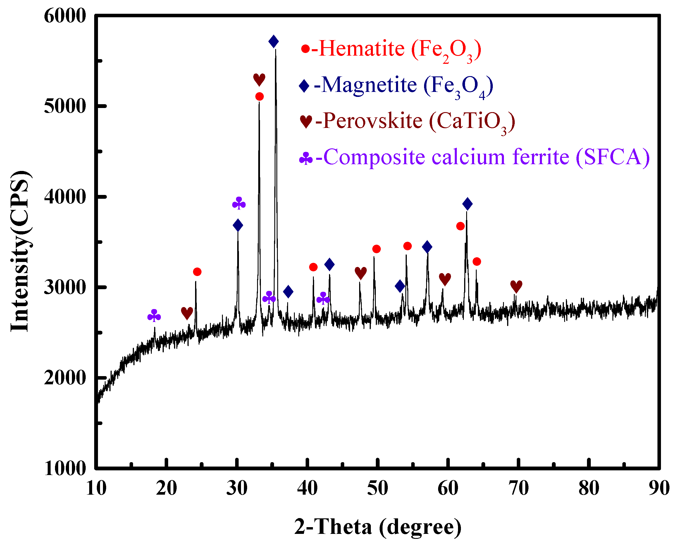
The VTM sinter samples used in this study were obtained from one of iron and steel companies in China. The main chemical composition of the sinter is shown in Table 1. The contents of total iron (TFe), TiO2 and V2O5 were 50.72%, 5.27% and 0.38%, respectively. The binary basicity (CaO/SiO2) was 1.99. The phase composition of the VTM sinter was investigated using X-ray diffraction (XRD). The results in Figure 1 indicate that the main phases of the sinter sample were composed of hematite (Fe2O3), magnetite (Fe3O4), perovskite (CaTiO3) and composite calcium ferrite (SFCA). Perovskite is a typical feature of VTM sinter due to the high content TiO2 in the VTM concentrate.

Table 1.
Main chemical composition of the VTM sinter, wt%.
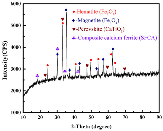
Figure 1.
XRD pattern of the VTM sinter.
2.2. Methods
The softening–melting experiment was carried out by referring to the Chinese standard of GB/T 34211–2017 [23] (iron ores—method for determination of iron reduction softening drippinger performance under load). A schematic diagram of the apparatus and the detailed experimental procedure can be found to the literature [22]. Before charging the VTM sinter sample in the crucible, about 80 g coke sample was placed at the bottom of the graphite crucible, then 500 g VTM sinter was charged into it, and then another 80 g coke was placed on the top of the sinter. The particle size of the VTM sinter and coke is 10~12.5 mm. The height of the VTM sinter in the crucible was measured and recorded as the initial height (H0). Then, the graphite crucible charged the sample was introduced into the tube furnace, a pressure bar made by graphite was put on the surface of upper coke. A load of 2 kg/cm2 was applied to simulate the pressure in BF. The heating rate before and after 850 °C is 10 °C/min and 5 °C/min, respectively. When the temperature of apparatus reaches 500 °C, 5 L/min of reducing gas with different components was introduced. As the charge was softened and melted, the liquid slag or iron will drip down and be quenched in oil. The composition of the reducing gas is given in Table 2.

Table 2.
Composition of reducing gas, vol%.
The characteristic parameters obtained from the softening–melting test are defined in Table 3. The softening onset (T10) and ending temperature (T40) indicate the temperature at which the height of burden shrinks by 10% and 40%, respectively. Ts refers to the temperature when the pressure drop increases significantly, and Td is the temperature when liquid iron or molten slag drips down. Thereafter, the softening temperature interval and melting temperature interval can be obtained as ΔT1 = T40-T10 and ΔT2 = Td-Ts. Furthermore, T△Pm represents the temperature at which the pressure drop reaches the maximum value. The integral of pressure drop curve as a function of melting temperature interval is defined as the gas permeability index (SD) [23].

Table 3.
Characteristic parameters for the softening–melting experiment.
3. Results and Discussion
3.1. Softening–Melting Properties
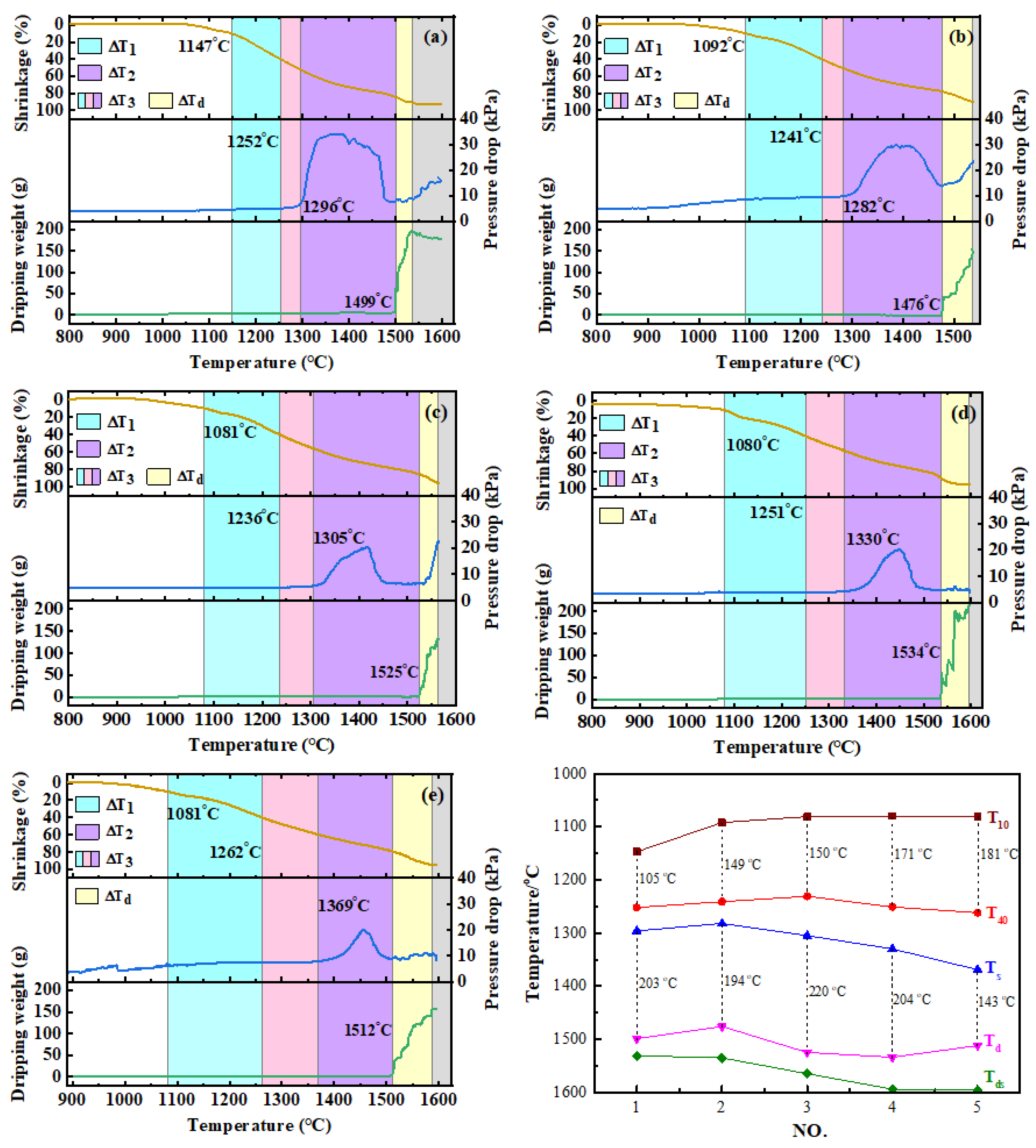
The results of softening–melting properties are shown in Table 4 and Figure 2. It can be seen from the table that when the CO content in the reducing gases increased from 30 vol% to 50 vol% (No. 1 and 2), all the characteristic temperatures of T10, T40, Ts and Td decreased. The softening interval became wider, while the melting interval shrank. This is due to the fact that with the increase in reduction potential, high valence iron oxides are more likely to be reduced to wustite (FeO) [13,16]. Thus, T10 decreased distinctly. By increasing the H2 content (No.2–No. 5), the temperature of T10 first decreased and then remained almost unchanged, from 1092 °C to about 1080 °C. However, the softening ending temperature of T40 decreased first and then increased significantly. The softening interval of △T1 increased continuously. This may be due to the increase in H2 content to above 15 vol%, which would promote the reduction of FeO to metallic iron. The FeO required for slag formation decreased rapidly, so T40 started to rise. Similarly, the melting onset temperature of Ts increased significantly with increase in the H2 content. Meanwhile, the dripping temperature of Td increased first and then decreased. It is noteworthy to mention that the melting–dripping interval (△T2), which has an important influence on the permeability of the burden layer, increased first and then decreased. The duration of dripping procedure (△Td) of 25 vol% H2 lasted longer than other conditions. In addition, the temperature of maximum pressure drop continued to increase. The results of softening–melting properties indicated that when the H2 content was increased, the position of the melting–dripping zone in BF moved downwards, which is beneficial to smelting going smoothly.

Table 4.
The results of softening–melting experiments.
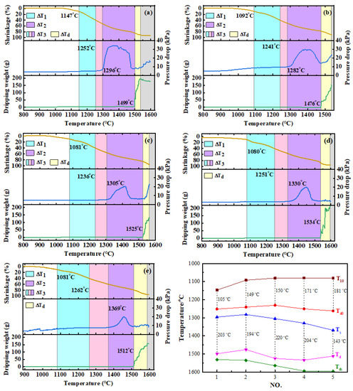
Figure 2.
Softening–melting performance of burden under different conditions. (a) NO.1, (b) NO.2, (c) NO.3, (d) NO.4, (e) NO.5), (f) Characteristic temperatures.
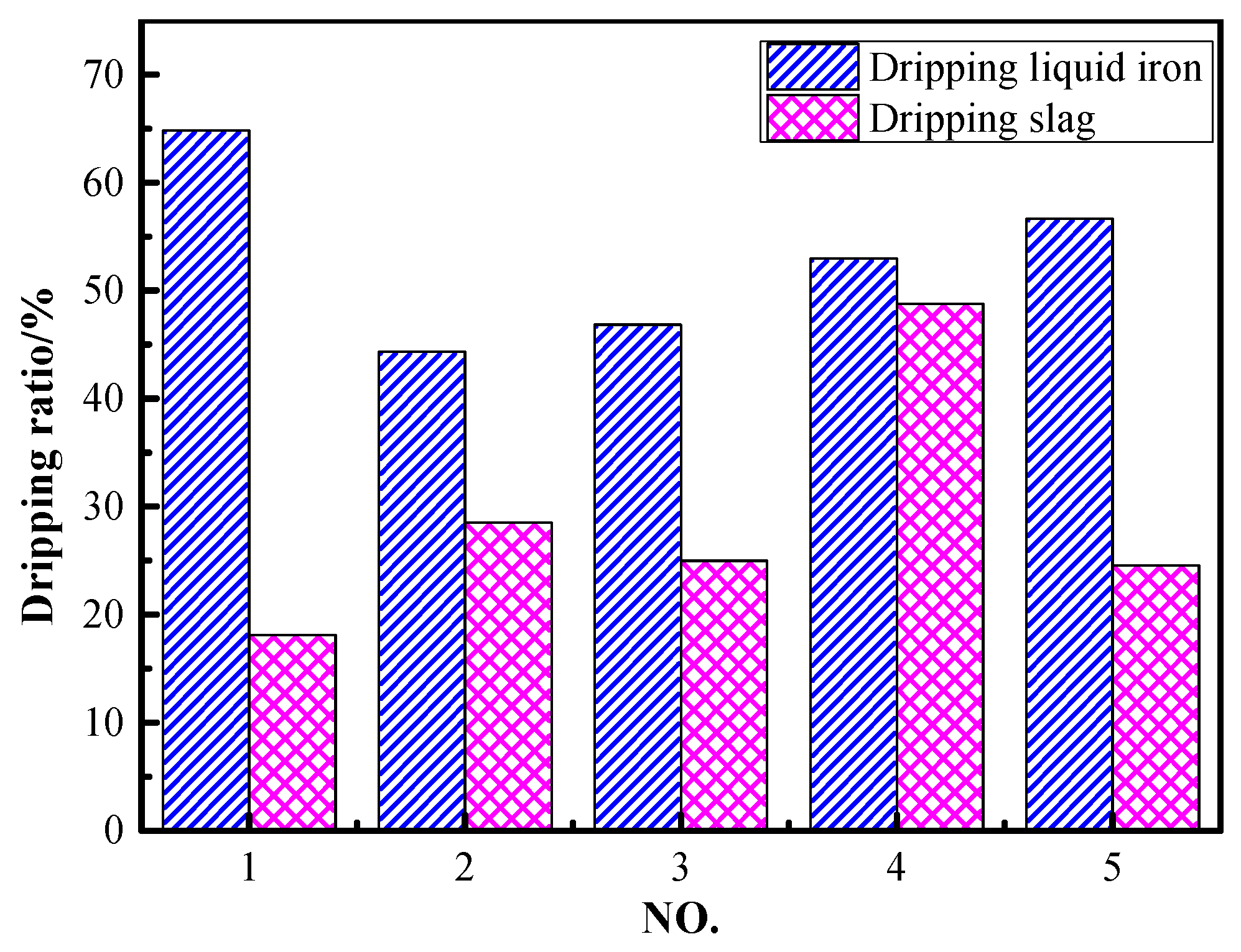
The dripping ratio of liquid iron and slag during the softening–melting and dripping process is given in Figure 3. The dripping ratio of liquid iron and slag under the conditions of 30 vol% CO and 70 vol% N2 was 64.8% and 18.1%, respectively. It can be observed that the dripping ratio of liquid iron decreased to 44.3% while the dripping slag increased to 28.5% when the CO content was increased to 50 vol%. Compared to the results of NO. 2~NO. 5, the dripping ratio of liquid iron increased gradually from 44.3% to 56.7% with the increase in H2 content in reducing gas. It can be deduced that increasing H2 content promoted the reduction of iron-bearing oxides, as well as the carburization of iron. The dripping slag increased first and then decreased with H2 contents in the range of 5~15 vol%. This may be attributed to the fact that H2 promoted the reduction and liquid iron-slag separation processes. However, as iron oxides were reduced and titanium oxides were dissociated, the reduction of titanium would also be promoted. If titanium oxides were over-reduced to form Ti(C,N), it would make the viscosity of the slag rise distinctly. As a result, the dripping of slag was inhibited. The study by Qie et al. also demonstrated that the optimal H2 content was between 10~15 vol% when ordinary ore pellets were used [16].
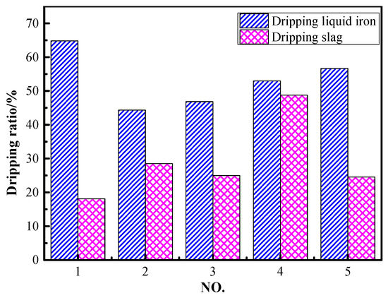
Figure 3.
Dripping ratio of liquid iron and slag under different conditions.
3.2. Gas Permeability under Different Atmosphere
In the softening–melting procedure, the maximum pressure drop is an important reference index to reflect the gas permeability of the burden. The maximum pressure drop represents the pressure resistance by the burden in the blast furnace. The maximum pressure drop (△Pm) shown in Table 2 indicated that it decreased gradually with the increase in the H2 content. This may be attributed to the reason that increasing the H2 content accelerated the reduction of iron oxides and the formation of metallic iron. It means less FeO would be left for slagging; thus, the △Pm was decreased. Another reason is that the size of the H2 and H2O molecules is much smaller than that of CO and CO2. As the proportion of H2 in the reducing gas increased, the gas is easier to pass through the burden. Hence, the permeability of the charge can also be improved [13,16].
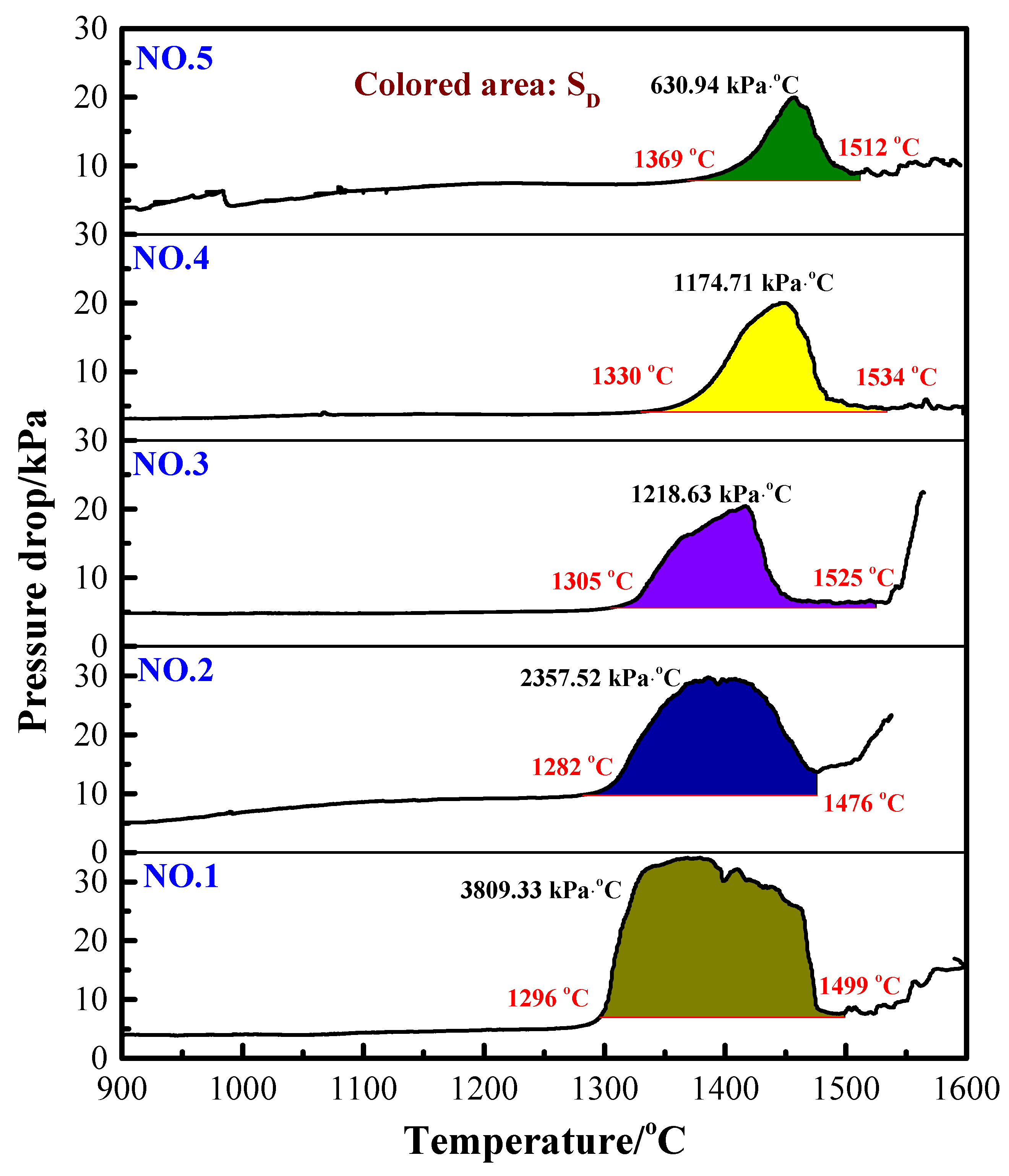
The value of SD representing the gas permeability in the melting–dripping procedure is shown in Figure 4. The higher the SD value, the worse the permeability. The results indicate that with the increase in H2 content in the reducing gas, the total characteristic value SD of the burden decreased correspondingly. This is because as the H2 content increased, the melting–dripping interval was narrowed, the maximum pressure drop decreased and the gas permeability of the burden layer improved. Therefore, it can be concluded that injection of H2-rich gas is beneficial to improve the permeability of VTM sinter in BF smelting process.
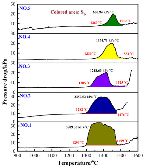
Figure 4.
Gas permeability index (SD) for reducing gas with different H2 contents.
3.3. Phase Transformation of VTM Sinter during the Softening–Melting Procedure
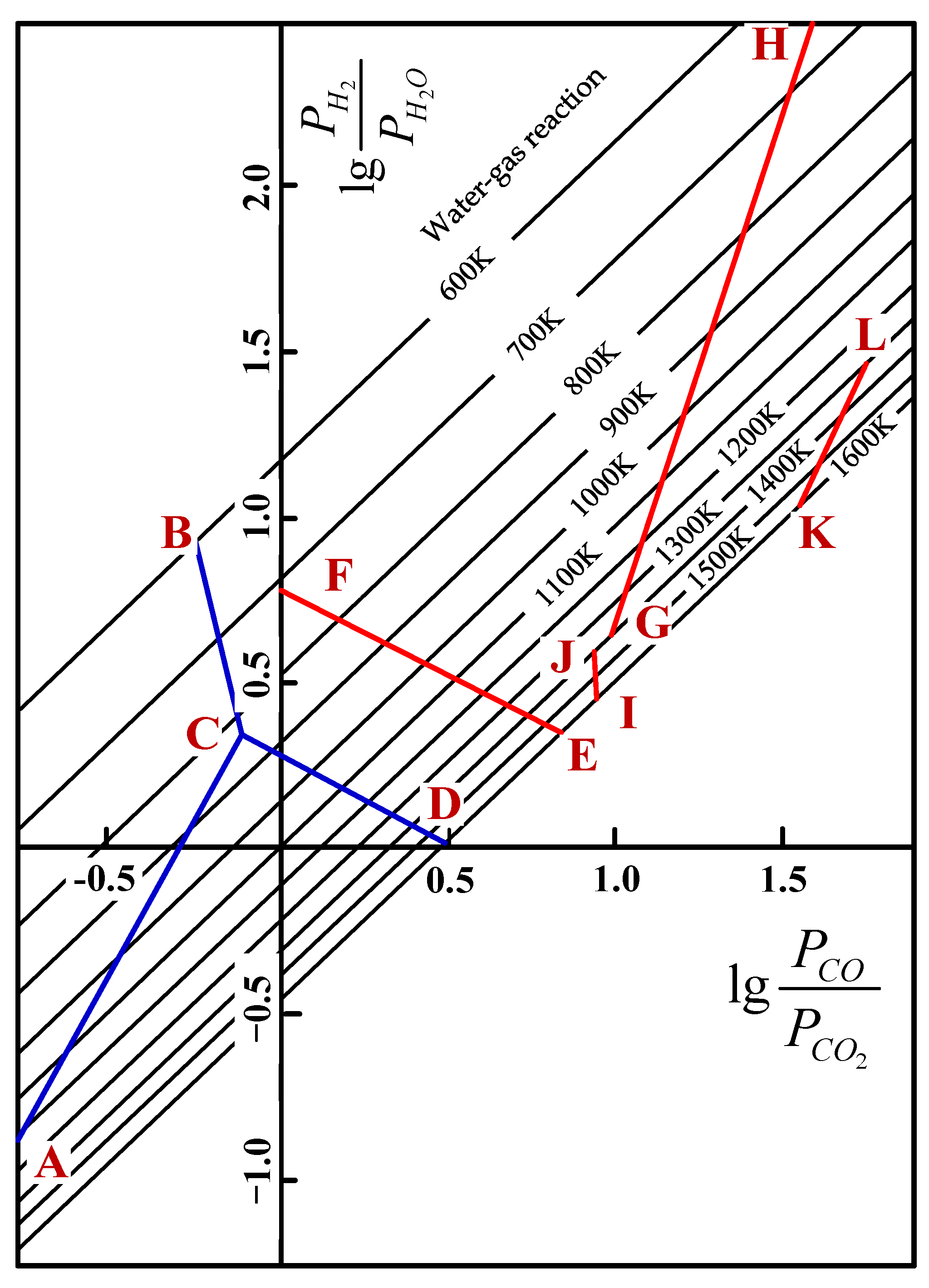
During the softening–melting process, the VTM sinter experienced different procedures, such as solid state reduction, softening to form initial slag and metallic iron carburization, as well as the dripping of slag or metal. With respect to the solid state reduction, the reactions of the main iron and titanium oxides that are reduced by H2 and CO are listed in Table 5. Hematite and SFCA can be easily reduced by H2 or CO; thus, they were not discussed in this paper. For each oxide, they can be reduced by H2 or CO. Taking FeO as an example, the Gibbs free energy as a function of temperature of reducing FeO by H2 or CO (Equations (1) and (2)) can be obtained from FactSage software or elsewhere. Then, the quantitative relationship between and can be calculated, and the results for different reactions are shown in Figure 5 [24,25]. In the actual C-H-O system, the water–gas reaction (Equation (3)) also existed, and its equilibrium relationship is also given in Figure 5.

Table 5.
Main reactions of reducing iron and titanium oxides by H2 and CO.
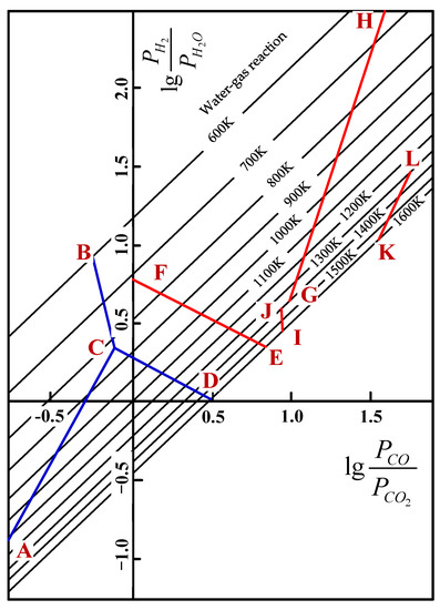
Figure 5.
Equilibrium diagram of reducing titanium and iron oxides in C-H-O system [24].
The results in Figure 5 show that the reduction of iron oxide (AC, BC, CD) is relatively easier, since the equilibrium components of both PH2/PH2O and PCO/PCO2 are lower than the reduction of Ti- and Fe-bearing oxides. FeO is not stable at lower temperatures and Fe3O4 is reduced directly to Fe (BC). At temperatures above 1100 K, PH2/PH2O is always less than PCO/PCO2 for the reduction of FeO, Fe2TiO4 and FeTiO3. It indicates that the thermodynamic conditions of reducing by H2 at high temperature are better than reducing by CO, and it is well accepted that the reduction capacity and utilization ratio of H2 are higher than CO at high temperatures. It can be inferred from the lines of GH, IJ and KL that when FeTiO3 and FeTi2O5 are reduced by H2-H2O or CO-CO2 mixtures, the reduction potential of the mixtures is increased with the increase in temperature. It means the equilibrium components of both PH2/PH2O and PCO/PCO2 are decreased with the increase in temperature. However, with respect to the lines of EF and CD, the reduction of Fe2TiO4 and FeO is different from that of FeTiO3 and FeTi2O5. By increasing the temperature, the reduction potential of H2-H2O increases, while that of CO-CO2 decreases. That is to say, PH2/PH2O decreases while PCO/PCO2 increases correspondingly. The equilibrium compositions of or for the reaction KL are high, which reveals that the reduction of FeTi2O5 is relatively difficult. The trend of lines CD, EF, GH and KL also reveals that increasing the H2 content can reduce the temperature of forming metallic iron, which is more beneficial to these reduction reactions. As a result, the injection of H2-rich gas is beneficial to the reduction of Ti- and Fe-bearing oxides that are difficult to reduce.
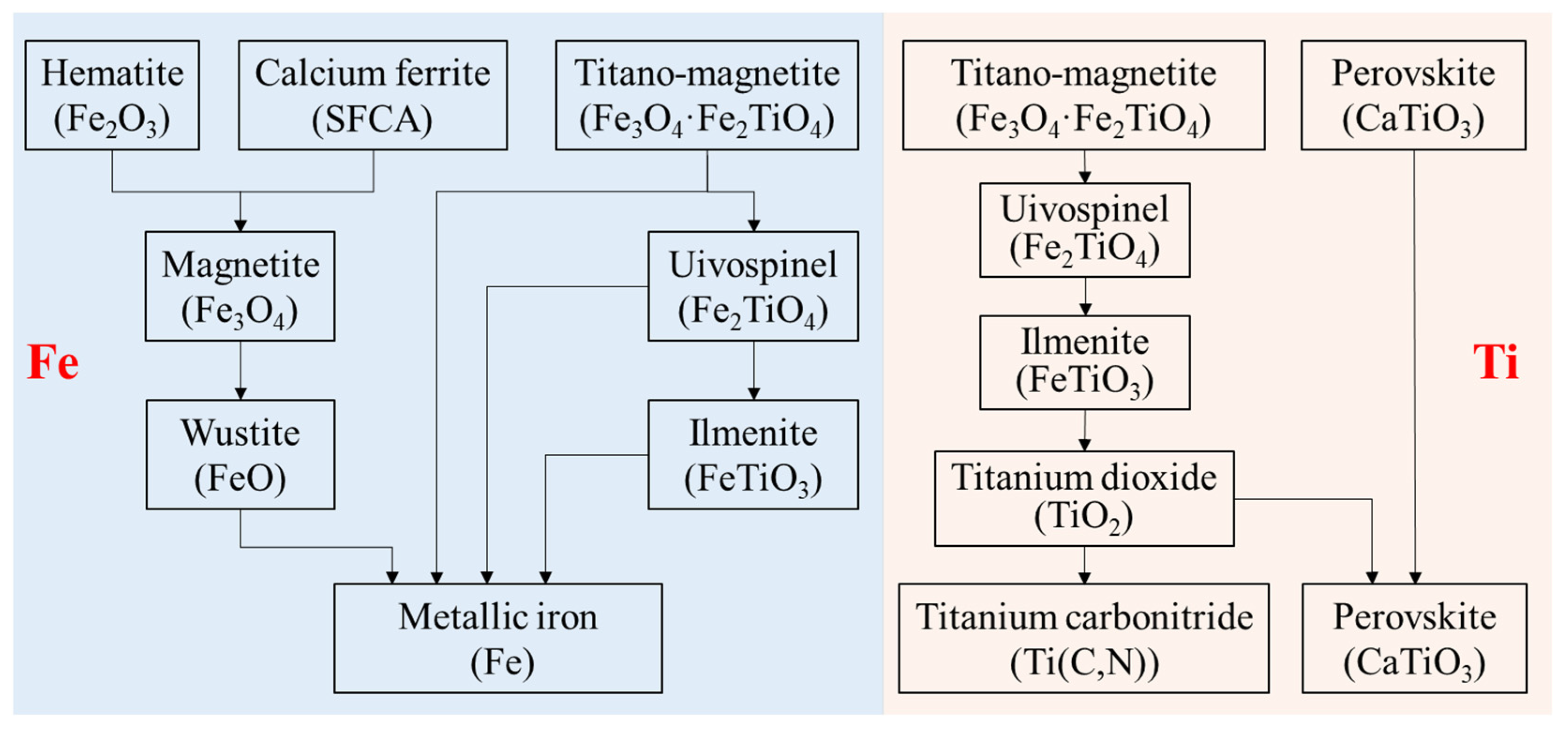
Based on the above thermodynamic analysis and experimental results, the migration route of Fe and Ti in VTM sinter during the softening–melting process can be summarized in Figure 6. The Fe-bearing phases, including hematite (Fe2O3), composite calcium ferrite (SFCA) and titano-magnetite (Fe3O4·Fe2TiO4), would be reduced stepwise to low-valence state. Ti mainly existed in perovskite (CaTiO3) and titano-magnetite in the VTM sinter. Titano-magnetite is marked as magnetite (Figure 1), since their crystal structures are relatively close. As can be seen from Figure 5, the reduction of Ti- and Fe-bearing phases were more difficult than iron oxides. Titano-magnetite was reduced to form uivospinel (Fe2TiO4) and then to ilmenite (FeTiO3). As FeTiO3 was reduced, TiO2 will be formed, which can be further reduced into titanium carbonitride (Ti(C,N)) [20,21,22,25]. However, the formation of Ti(C,N) in the H2-rich state is worthy of further study because it is an important factor affecting the BF smelting of VTM ore. According to our previous studies [22], vanadium oxide is more easily reduced than titanium oxide, and it will be reduced into metallic state. The metallic vanadium mainly existed with metallic iron and most of the vanadium will enter the dripping liquid iron.
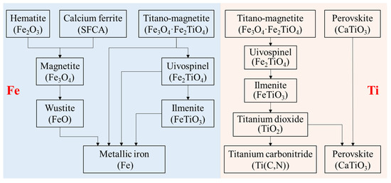
Figure 6.
Migration of Ti and Fe in VTM sinter during the softening–melting process.
3.4. Slag Evolution during the Softening–Melting Process
As we know, when high-valence iron oxides were reduced to FeO, it is an important component during the slag evolution process. FeO is the substance that resulted in forming initial slag as well as the deformation of the burden. However, as the reduction proceeded, the content of FeO in slag decreased gradually from the initial slag to the ultimate slag. The dripping temperature mainly depends on the fluidity of the initial slag dripped from the dripping zone. If the fluidity of the initial slag is poor, and the dripping process is correspondingly prolonged, which is characterized by high dripping temperature. The FeO content plays a decisive role in the fluidity of the initial slag. When the H2 content is low, increasing the H2 content in the reducing gas can significantly improve the reduction ability of the gas. At the same temperature, the FeO content in the initial slag can be reduced, and the dripping temperature will be increased.
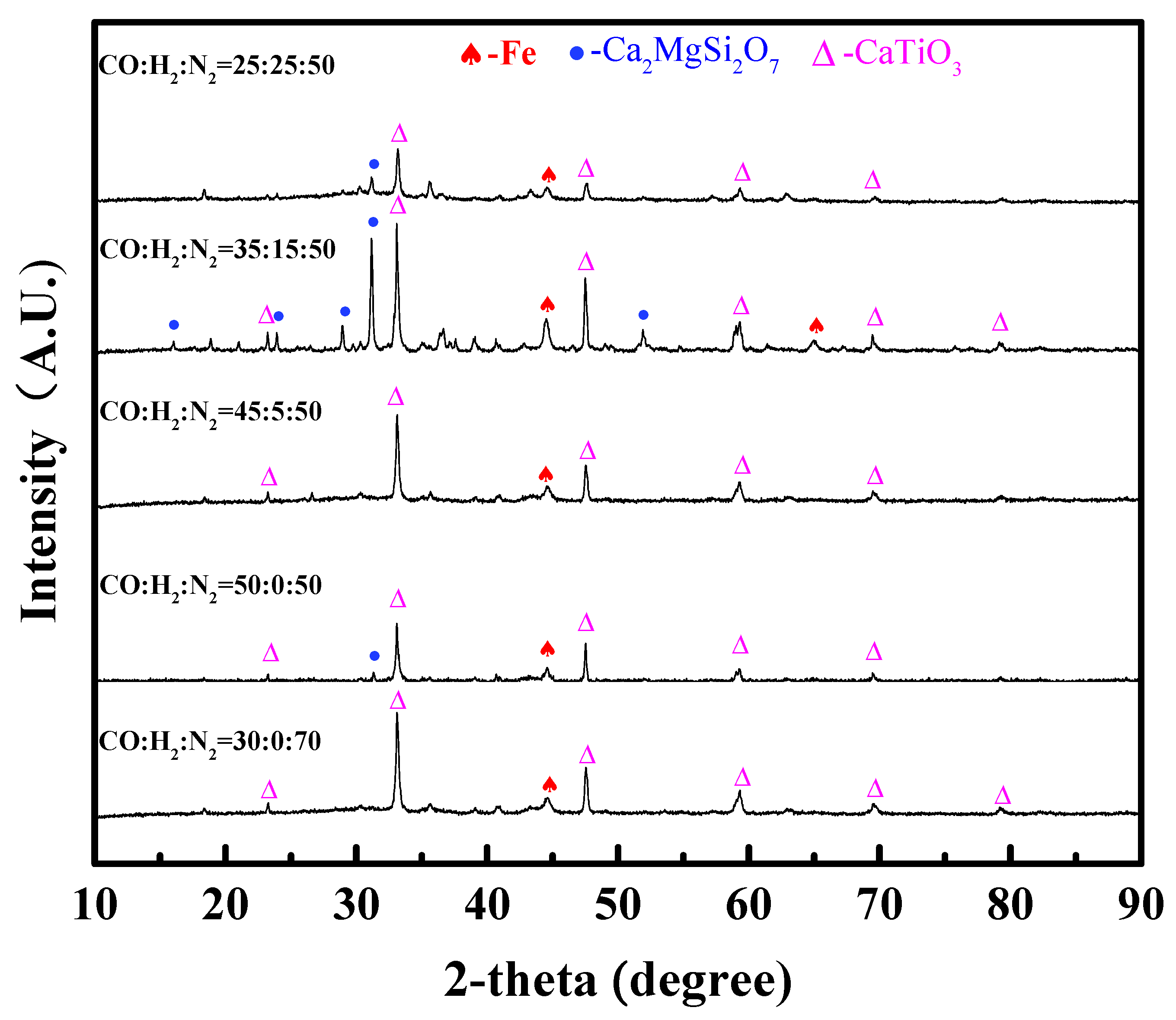
Figure 7 shows the XRD patterns of the dripping slag. It can be seen that the main phases in the dripping slag are magnesium melilite (Ca2MgSi2O7) (melting point 1450 °C) and perovskite (CaTiO3) (melting point 1420 °C) and are mixed with a small amount of metal iron. The content of H2 had little influence on the phase composition of the dripping slag. When the content of H2 was 15 vol%, the diffraction peak of magnesia melilite was very obvious. Although the difference between these XRD patterns was not distinct, H2-rich gases had significant influence on the slag-forming process.
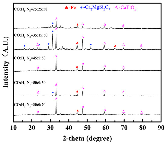
Figure 7.
XRD patterns of the dripping slag with different contents of H2 in reducing gas.
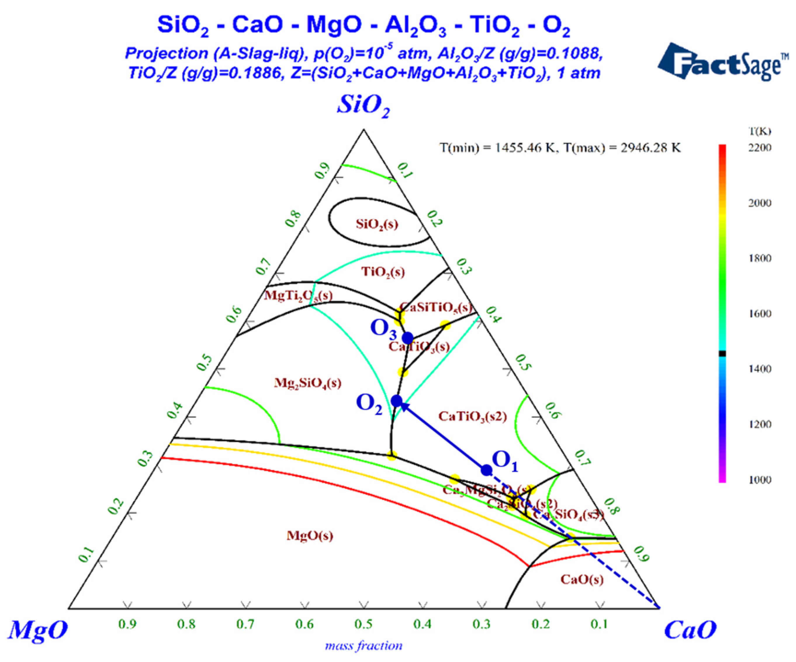
In order to predict the behavior of ultimate slag, a pseudo-ternary phase diagram of CaO–SiO2–MgO(–Al2O3–TiO2) was calculated by using FactSage 8.0. The results are plotted in Figure 8. The contents of TiO2 and Al2O3 were set at 23.65 wt% and 11.58 wt%, assuming that iron oxides of VTM sinter were completely reduced to metallic iron. Spot O1 located the composition of the slag by neglecting iron and other minuscule components. If the slag was molten and uniform when the temperature was increased to above Td, the slag would crystallize from O1 to O2 by precipitating perovskite (CaTiO3) during the cooling process. Perovskite was observed in all the XRD patterns, which may be due to the fact that it has already been formed in the sinter. Then, CaTiO3 and Mg2SiO4 were co-crystallized after reaching spot O2, and the liquid phase line moved from O2 to O3. However, Mg2SiO4 was not observed in the XRD patterns, since the dripped slag was quenched in oil. Spot O3 is a ternary eutectic point, at which Mg2SiO4, CaTiO3 and CaAl2Si2O8 were co-crystallized. The diffraction peaks of Ca2MgSi2O7 rather than CaAl2Si2O8 were observed in the XRD patterns. The difference between the actual slag phases and theoretical analysis may be influenced by dynamic factors and ununiform state during the crystallization process.
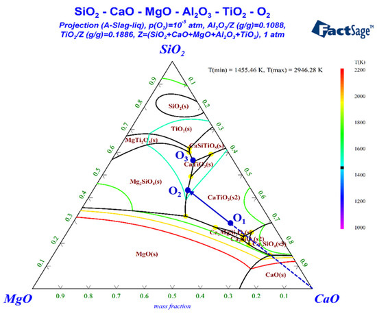
Figure 8.
Phase diagram of SiO2-CaO-MgO-(Al2O3-TiO2).
4. Conclusions
In this study, the softening–melting behaviors of VTM sinter in H2-rich gases were investigated. The experimental results demonstrated that by increasing the H2 content in the reducing gas, the softening onset temperature of T10 first decreased and then remained almost unchanged, from 1092 °C to about 1080 °C. The softening interval (ΔT1) increased continuously. The melting onset temperature (Ts) increased significantly with the increase in the H2 content, while the melting–dripping interval (ΔT2) increased first and then decreased. The maximum pressure drop of the burden decreased gradually (29.76 kPa→19.97 kPa) with the increase in H2 content. The total characteristic value (SD) also decreased noticeably (2357.52 kPa·°C→630.94 kPa·°C), which proved that the injection of H2-rich gas is beneficial for improving the permeability of the VTM sinter in the BF smelting process. The thermodynamic analysis indicated that Ti- and Fe-bearing phases were more difficult to be reduced than iron oxides, and H2-rich gas was beneficial for the reduction of Ti- and Fe-bearing oxides. Titano-magnetite will be reduced stepwise to form Fe2TiO4 and then in the order of FeTiO3→TiO2→Ti(C,N). FeO was an important component during the softening and melting process. Perovskite and silicate were the main phases in the dripping slag.
Author Contributions
Conceptualization, R.X. and J.Z.; methodology, R.X. and J.Z.; software, X.G.; validation, R.X. and X.G.; formal analysis, R.X.; investigation, R.X. and X.G.; resources, Z.Y.; data curation, X.G.; writing—original draft preparation, R.X.; writing—review and editing, Z.Y. and C.B.; supervision, S.Z. and C.B.; project administration, W.Y. and J.D.; funding acquisition, C.B. All authors have read and agreed to the published version of the manuscript.
Funding
This research was funded by the National Natural Science Foundation of China, grant number U2003215, the National Key R&D Program of China (2022YFC3901401) and the China Baowu Low Carbon Metallurgy Innovation Foudation—BWLCF202102.
Institutional Review Board Statement
Not applicable.
Informed Consent Statement
Not applicable.
Data Availability Statement
Some or all data that support the findings of this study are available from the corresponding author upon reasonable request.
Conflicts of Interest
The authors declare no conflict of interest.
References
- Pang, Z.D.; Lv, X.W.; Jiang, Y.Y.; Ling, J.W.; Yan, Z.M. Blast furnace ironmaking process with super-high TiO2 in the slag: Viscosity and melting properties of the slag. Metal. Mater. Trans. B Process Metall. Mater. Process Sci. 2020, 51, 722–731. [Google Scholar] [CrossRef]
- Cheng, G.J.; Liu, J.X.; Liu, Z.G.; Chu, M.S.; Xue, X.X. Non-isothermal reduction mechanism and kinetics of high chromium vanadium–titanium magnetite pellets. Ironmak. Steelmak. 2014, 42, 17–26. [Google Scholar] [CrossRef]
- Sui, Y.L.; Guo, Y.F.; Jiang, T.; Qiu, G.Z. Separation and recovery of iron and titanium from oxidized vanadium titano-magnetite by gas-based reduction roasting and magnetic separation. J. Mater. Res. Technol. 2019, 8, 3036–3043. [Google Scholar] [CrossRef]
- Guo, X.F.; Dai, S.J.; Wang, Q.Q. Influence of different comminution flowsheets on the separation of vanadium titano-magnetite. Miner. Eng. 2020, 149, 106268. [Google Scholar] [CrossRef]
- Zhao, W.; Chu, M.S.; Wang, H.T.; Liu, Z.G.; Tang, J.; Ying, Z.W. Reduction behavior of vanadium-titanium magnetite carbon composite hot briquette in blast furnace process. Powder Technol. 2018, 342, 214–223. [Google Scholar] [CrossRef]
- Chen, W.B.; Dong, Z.Q.; Jiao, Y.; Liu, L.L.; Wang, X.D. Preparation, sintering behavior and consolidation mechanism of vanadium–titanium magnetite pellets. Crystals 2021, 11, 188. [Google Scholar] [CrossRef]
- Gan, M.; Sun, Y.F.; Fan, X.H.; Ji, Z.Y.; Lv, W.; Chen, X.L.; Jiang, T. Preparing high-quality vanadium titano-magnetite pellets for large–scale blast furnaces as ironmaking burden. Ironmak. Steelmak. 2020, 47, 130–137. [Google Scholar] [CrossRef]
- Xiang, J.Y.; Wang, X.; Yang, M.R.; Wang, J.; Shan, C.; Fan, G.Q.; Qiu, G.B.; Lv, X.W. Slag–foaming phenomenon originating from reaction of titanium-bearing blast furnace slag: Continuous monitoring of foaming height and calibration. J. Mater. Res. Technol. 2021, 11, 1184–1192. [Google Scholar] [CrossRef]
- Fu, W.G.; Xie, H.E. Progress in technology of vanadium–bearing titanomagnetite smelting in Pangang. Steel Res. Int. 2011, 82, 501–504. [Google Scholar] [CrossRef]
- Tang, J.; Chu, M.S.; Li, F.; Feng, C.; Liu, Z.G.; Zhou, Y.S. Development and progress on hydrogen metallurgy. Int. J. Min. Met. Mater. 2019, 27, 713–723. [Google Scholar] [CrossRef]
- Zhang, S.H.; Yi, B.W.; Guo, F.; Zhu, P.Y. Exploring selected pathways to low and zero CO2 emissions in China’s iron and steel industry and their impacts on resources and energy. J. Clean. Prod. 2022, 340, 130813. [Google Scholar] [CrossRef]
- Gao, X.D.; Zhang, R.; You, Z.X.; Yu, W.Z.; Dang, J.; Bai, C.G. Use of hydrogen-rich gas in blast furnace ironmaking of V-bearing titanomagnetite: Mass and energy balance calculations. Materials 2022, 15, 6078. [Google Scholar] [CrossRef] [PubMed]
- Yang, G.Q.; Zhang, J.L.; Chen, Y.X.; Wu, Q.Y.; Zhao, Z.Y.; Zhao, J. Influence of hydrogen content of bosh gas on softening–melting property of iron–bearing burden material. Iron Steel 2012, 47, 14–18. [Google Scholar] [CrossRef]
- Pistorius, P.C.; Gibson, J.; Jampani, M. Natural gas utilization in blast furnace ironmaking: Tuyere injection, shaft injection and prereduction. In Applications of Process Engineering Principles in Materials Processing, Energy and Environmental Technologies; Springer: Cham, Switzerland, 2017; pp. 283–292. [Google Scholar]
- Jampani, M.; Gibson, J.; Pistorius, P.C. Increased use of natural gas in blast furnace ironmaking: Mass and energy balance calculations. Metal. Mater. Trans. B Process Metall. Mater. Process Sci. 2019, 50, 1290–1299. [Google Scholar] [CrossRef]
- Qie, Y.N.; Lyu, Q.; Liu, X.J.; Li, J.P.; Lan, C.C.; Zhang, S.H.; Yan, C.J. Effect of hydrogen addition on softening and melting reduction behaviors of ferrous burden in gas–injection blast furnace. Metal. Mater. Trans. B Process Metall. Mater. Process Sci. 2018, 49, 2622–2632. [Google Scholar] [CrossRef]
- Babich, A.; Yaroshevskii, S.; Formoso, A. Co-injection of noncoking coal and natural gas in blast furnace. Trans. Iron Steel Inst. Jpn. 2007, 39, 229–238. [Google Scholar] [CrossRef]
- Yu, J.W.; Hu, N.; Xiao, H.X.; Gao, P.; Sun, Y.S. Reduction behaviors of vanadium-titanium magnetite with H2 via a fluidized bed. Powder Technol. 2021, 385, 83–91. [Google Scholar] [CrossRef]
- Sui, Y.L.; Guo, Y.F.; Jiang, T.; Xie, X.L.; Wang, S.; Zheng, F.Q. Gas-based reduction of vanadium titano-magnetite concentrate: Behavior and mechanisms. Int. J. Miner. Metall. Mater. 2017, 24, 10–17. [Google Scholar] [CrossRef]
- Zhou, K.; Song, J.Q.; You, Z.X.; Xie, H.E.; Lv, X.W. Softening–melting properties and slag evolution behavior of high titanium sinter. ISIJ Int. 2020, 60, 1409–1415. [Google Scholar] [CrossRef]
- Hu, Q.Q.; Ma, D.L.; Zhou, K.; Liu, Y.J.; You, Y.; You, Z.X.; Lv, X.W. Phase transformation and slag evolution of vanadium–titanium magnetite pellets during softening–melting process. Powder Technol. 2022, 396, 710–717. [Google Scholar] [CrossRef]
- Yin, C.; Zhang, S.F.; Yang, X.K.; Yuan, W.N.; Yu, W.Z.; Wen, L.Y.; Li, T.; Bai, C.G. Smelting vanadium–titanium magnetite by COREX process: Effect of V–Ti bearing pellet ratio on the softening and melting behavior of mixed burden. Metall. Mater. Trans. B Process Metall. Mater. Process Sci. 2021, 52B, 4096–4108. [Google Scholar] [CrossRef]
- Standardization Administration of China. Iron Ores—Method for Determination of Iron Reduction Softening Drippinger Performance under Load. Available online: https://c.gb688.cn/bzgk/gb/showGb?type=online&hcno=94D8E7D936DCB10202AEAF3473FD85FC2017 (accessed on 19 January 2023).
- Du, H.G. Reduction procedure of vanadium titano-magnetite. In Principle of Smelting Vanadium Titano-Magnetite in Blast Furnace; Science Press: Beijing, China, 1996; pp. 127–131. [Google Scholar]
- Chen, J.W.; Jiao, Y.; Wang, X.D. Thermodynamic studies on gas-based reduction of vanadium titano-magnetite pellets. Int. J. Min. Met. Mater. 2019, 26, 822–830. [Google Scholar] [CrossRef]
Disclaimer/Publisher’s Note: The statements, opinions and data contained in all publications are solely those of the individual author(s) and contributor(s) and not of MDPI and/or the editor(s). MDPI and/or the editor(s) disclaim responsibility for any injury to people or property resulting from any ideas, methods, instructions or products referred to in the content. |
© 2023 by the authors. Licensee MDPI, Basel, Switzerland. This article is an open access article distributed under the terms and conditions of the Creative Commons Attribution (CC BY) license (https://creativecommons.org/licenses/by/4.0/).

