1. Introduction
High-pressure synthesis of the material is an important area for physics, chemistry, and material sciences [
1,
2,
3]. This method reduces the chemical reaction time, controls the evaporation of lighter elements [
4,
5], and can also be used to grow new materials that cannot be prepared at ambient pressure, such as superhard materials like diamond and cubic boron nitride [
6]. Generally, the sample space is very tiny for the pressure growth process, and due to this, a small sample size is always obtained [
7]. This issue has been clearly observed with the growth process of iron-based superconductor (FBS) [
8]. To overcome this problem, we need to find a good high-pressure growth method that can provide large crystals and bulk samples with high superconducting properties. However, the question is: which technique is more suitable to resolve these problems? [
9,
10].
There are two kinds of pressure techniques: (
a)
Solid-medium pressure techniques such as Hot Isostatic Pressure (HIP), Diamond Anvil Cell (DAC) Technique [
11], Multi-Anvil High-Pressure Apparatus, and cold synthesis [
11]. The properties of this technique are as follows: (i) It has a limited sample space of up to 0.5 cm
3, and due to this, the prepared sample size is usually small. (ii) The pressure and temperature distribution are not homogeneous. It generates undefined preparation conditions. (iii) Due to the pressure medium touching the sample, there is a great possibility of introducing the impurity phases. (iv) Also, the temperature gradient is not easy to control in the multizone furnace. (
b)
Gas pressure technique: The properties are as follows: (i) it has several cm
3 of sample space, and (ii) it is easy to create homogeneous temperature and pressure stability for a practically long growth time. (iii) The spatial temperature profile may be controlled, and it may be easy to control the partial gas pressure; (iv) the growth of the crystal is a comparatively easy process; (v) there is no possibility of introducing impurities from the pressure medium; (vi) sample chamber with an internal three-zone furnace with pressure up to 2–3 GPa and temperature ~2000 °C.
In the solid-medium pressure growth process, interactions between materials and instrument parts can introduce contamination and other issues due to the applied physical force, potentially leading to morphology problems like cracks and pores [
1]. Therefore, it is crucial to explore alternative techniques to address these challenges. The above-mentioned discussion suggests that the gas pressure technique can be a unique and attractive way to grow high-quality and large amounts of samples and to improve the superconducting properties of FBS [
12,
13]. These reasons motivated us to use high-pressure techniques for the growth of iron-based superconductors. One can note that the gas pressure techniques can be used to create a maximum pressure of up to 3 GPa with a small pressure chamber, whereas the solid-medium pressure technique can generate much higher pressure than the gas pressure techniques. Furthermore, in the gas pressure technique, the used gas must be highly pure because a large volume of gas is compressed in a small pressure chamber to generate a high gas pressure. Consequently, even a tiny quantity of gas impurity can have a significant impact on the sample’s growth and is undesirable from a safety perspective. Gas pressure techniques, like other pressure techniques, are also complex during sample loading because every part of the chamber needs to be positioned correctly for optimal operation.
In the case of FBS, few studies have been reported based on solid-pressure medium techniques where the sample size is enhanced from 10 μm to 300 μm with improved superconducting properties [
7,
8]. These reports suggest that more studies are needed in this direction by using different pressure techniques, such as the high-gas growth method, so that we can also prepare a large sample with high superconducting properties. In this paper, we have introduced the principle and more details about our high gas pressure and high-temperature synthesis (HP-HTS) technique that is available at our institute, “UNIPRESS”. Also, the current results based on iron-based superconductors using this HP-HTS method will be presented and discussed.
2. Principle of High-Pressure Technique
This HP-HTS has a compressor called the reciprocating compressor, which is based on the oil gas piston. The main working principle of the reciprocating compressor is based on Boyel’s law [
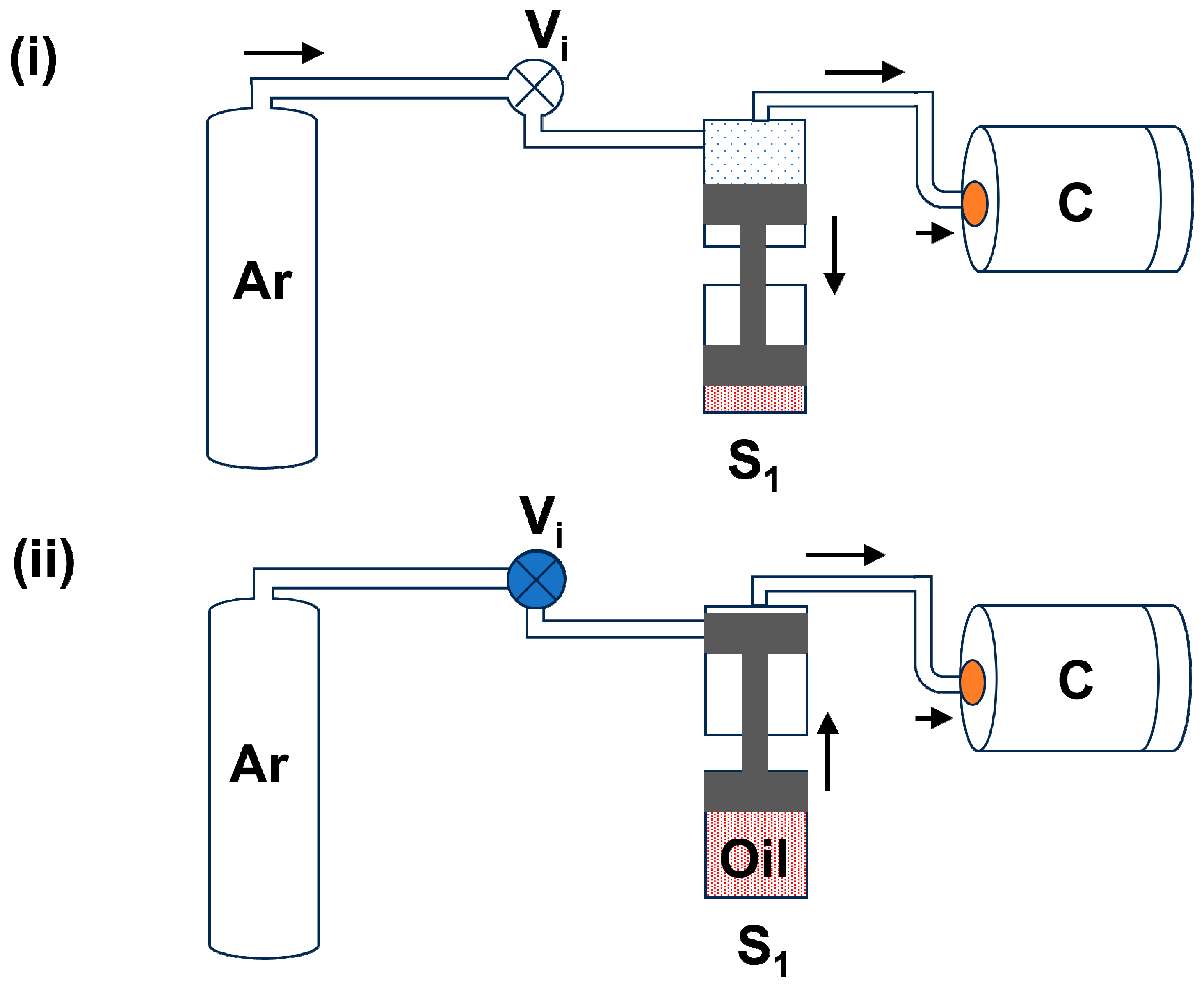
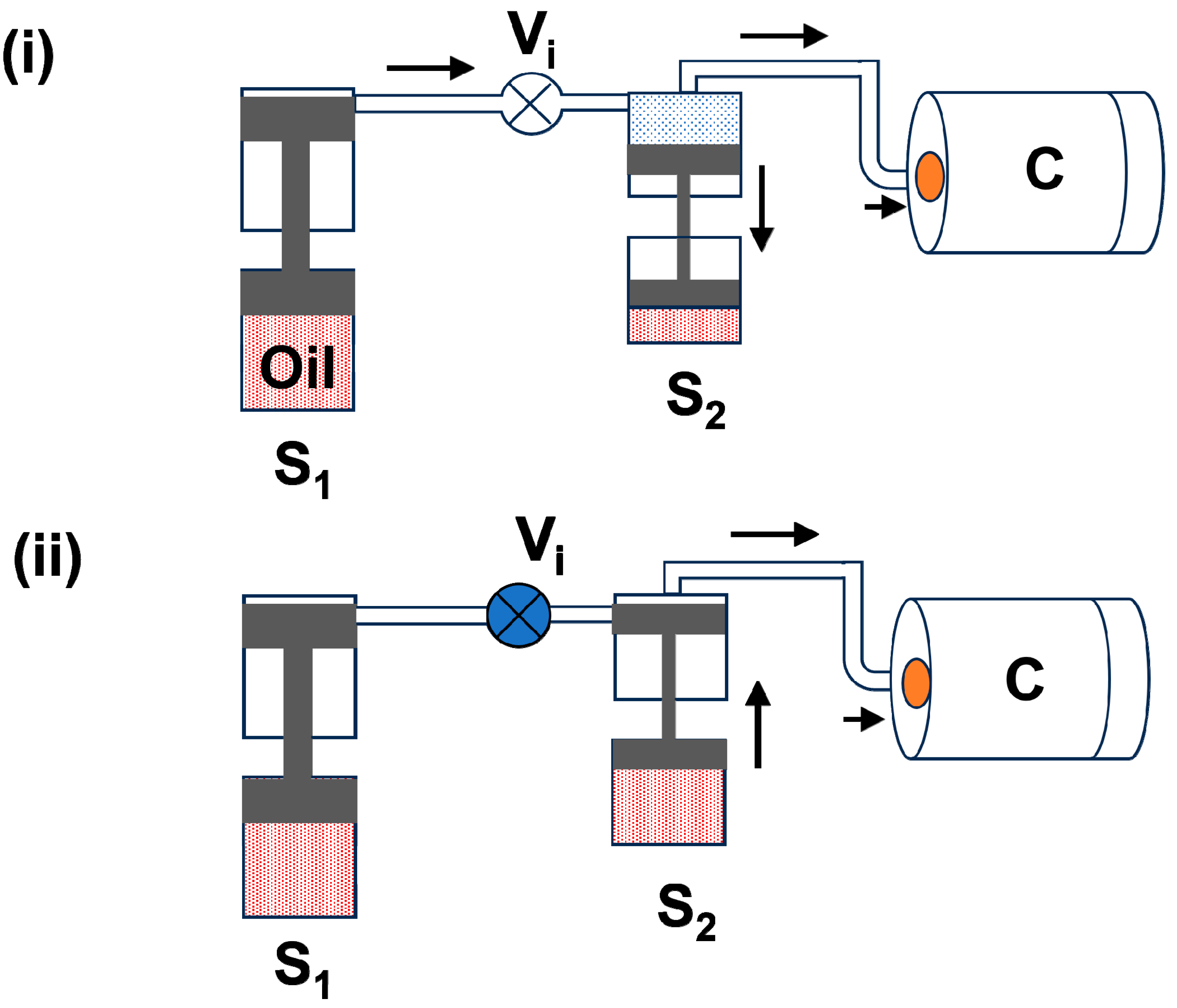
14], which states that the absolute pressure exerted by a given mass of an ideal gas is inversely proportional to the occupied volume. The piston compresses the gas and increases the gas pressure inside the chamber. The piston’s movement essentially operates in two modes of operation, depending on the required pressure. In the first mode, the oil is primarily located at the bottom of the piston, through which the piston can move in an upward direction to compress the gas by pushing more oil into the oil chamber, whereas by releasing oil into the oil tank through a key valve, the piston can return to its regular position. However, when high pressure (>0.4 GPa) is required, the piston must be operated in both forward and backward directions through the oil pressure. So, the lower side of the piston must have two separate oil chambers that can be operated through the oil pump to compress or release the gas pressure by adding or removing oil from one of the oil chambers. Generally, in our HP-HTS system, there are three piston cavities (piston chambers) attached to each other in a series to achieve the required high pressure. In order to safely generate high pressure and lower the possibility of mechanical problems, a significant volume of gas is compressed inside the pressure chamber through three-stage pistons. The systematic block diagram of the working principle of these pistons is shown below in various stages, especially to create high gas pressure.
(a) First-stage piston (S1): First, the gas bottle is opened, and the gas enters through the intake valve (V
i) into all piston cavities and the high-pressure chamber.
Figure 1i demonstrates the gas refilling process in the first piston cavity (S
1) and chamber (C). During this process, gas is filled in the upper part of the S
1 by moving the piston down to the oil tank. Basically, the piston moves down with the gas bottle pressure of ~200 bar. After 4–5 min, we close the intake valve (V
i) and move the piston in an upward direction slowly to pressurize the gas inside the chamber.
Figure 1ii depicts the movement of the piston in an upward direction in the S
1 cavity. Through this first stage, we can reach the maximum pressure of up to 800 bar, i.e., the gas pressure can increase from 200 bar to 800 bar.
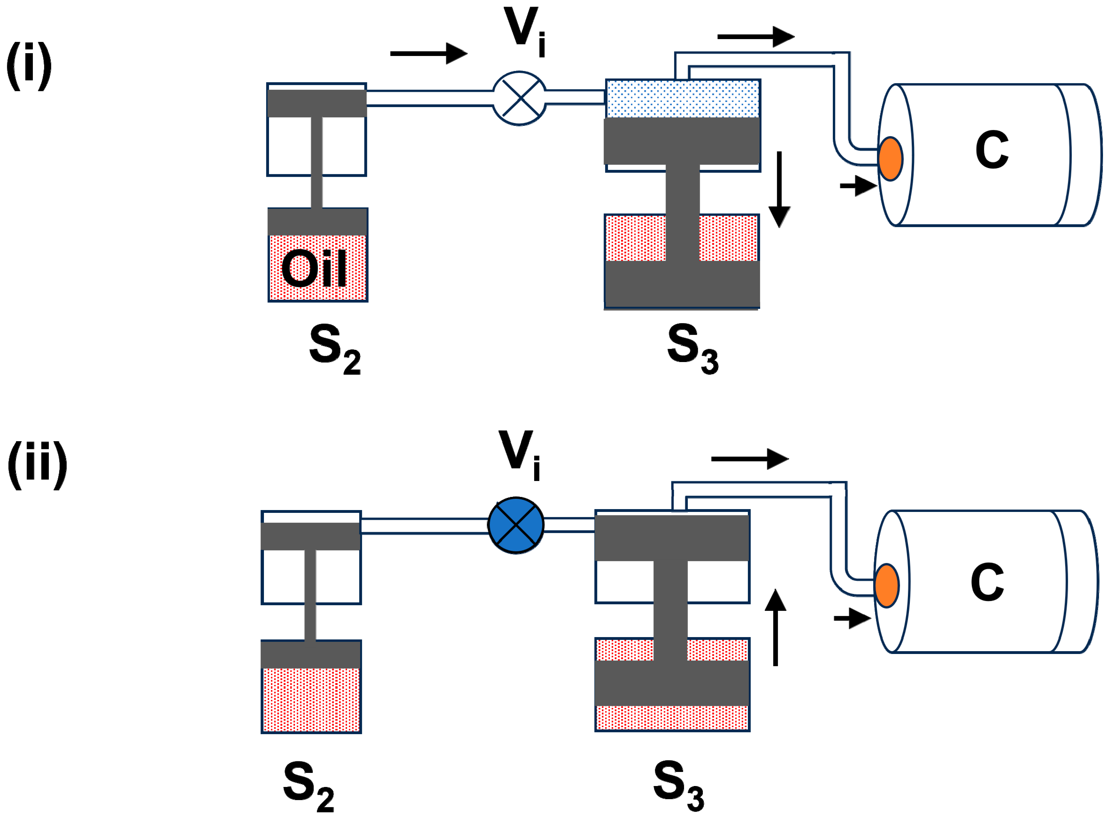
(b) Second-stage piston (S2): This stage is connected to the first-stage piston (S
1) and has a pressure of around 800 bar. There is again an oil-gas piston that moves down with the first-stage pressure of 800 bar, which is shown in
Figure 2i. Now, the intake valve (V
i) between S
1 and S
2 is closed, and the piston of S
2 moves upward slowly, which creates gas pressure inside the chamber up to 4000 bar. This process is similar to the first stage and is shown in
Figure 2ii.
(c) Third stage piston (S3): This stage piston has a bigger size than the first and second-stage pistons. Due to the second-stage pressure, this piston is moved to the down position, which is depicted in
Figure 3i. Once all gas pressure moves into the S
3 cavity and chamber, the intake valve (V
i) between S
2 and S
3 is closed. In the next step, the S
3 piston moves slowly in an upward direction through the oil-based pump and enhances the pressure inside the chamber (C). The maximum pressure achieved in S
3 can be reached at 1.8 GPa (18,000 bar).
Figure 3ii displays the block diagram of the third-stage piston movement to achieve the highest pressure. This stage plays an important role in reaching the ultimate pressure. Hence, this stage has a large piston chamber to collect more compressed gas and a powerful piston with a large oil tank to apply more force to compress the gas into the pressure chamber.
3. HP-HTS Technique at UNIPRESS
The HP-HTS facility designed at UNIPRESS is capable of producing a pressure of up to 1.8 GPa and a temperature of up to 1700 °C. One can use a one- or multi-zone furnace to create different temperatures, especially for a single crystal growth process [
9,
10,
12,
15]. Our current system is based on a three-stage oil-gas compressor to create high pressure, as discussed above. More advanced designs can produce pressure up to 3 GPa, which requires three pistons and a small diameter of the pressure chamber (C). Our HP-HTS technique is vital in synthesizing high-quality materials [
9,
10,
12,
15]. With the capability to generate high gas pressure, this system has multi-zone furnaces, real-time temperature measurement, and adaptability for various sample types and positions inside the pressure chamber. It is a versatile tool for growing single and polycrystalline samples across diverse material categories [
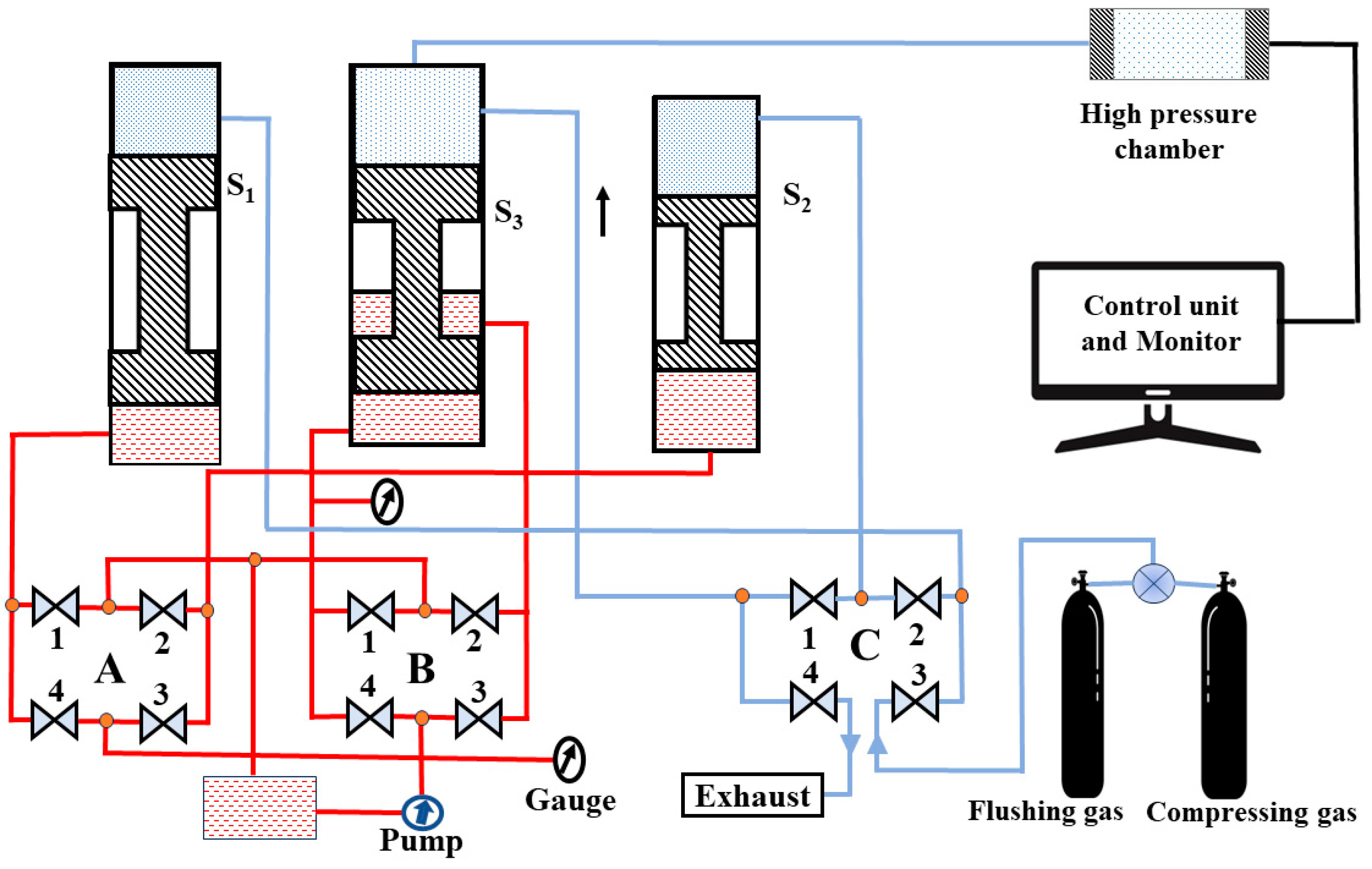
9]. The block diagram of our HP-HTS system is depicted in
Figure 4. The system has four main components: a high-pressure chamber, compressor, sample holder with furnace, and controller unit and monitor, which work cohesively to ensure precise and controlled pressurization, leak-free operation, and real-time temperature and pressure monitoring. These features empower high-pressure synthesis and sintering research, providing a platform for advancements in superconductivity research and applications.
The HP-HTS system which is currently used for the growth of FBS, is based on three pistons, as depicted in
Figure 4. These pistons are connected to each other and also to the pressure chamber. The first stage (S
1) generates the pressure for the second stage (S
2), the third stage (S
3), and the pressure chamber (C). In the next step, the first stage is disconnected, and the second-stage piston creates the pressure for the third stage (S
3) and pressure chamber. Finally, the third stage (S
3) starts to work and generate the maximum pressure inside the chamber, up to 1.8 GPa. More details about each part are given below:
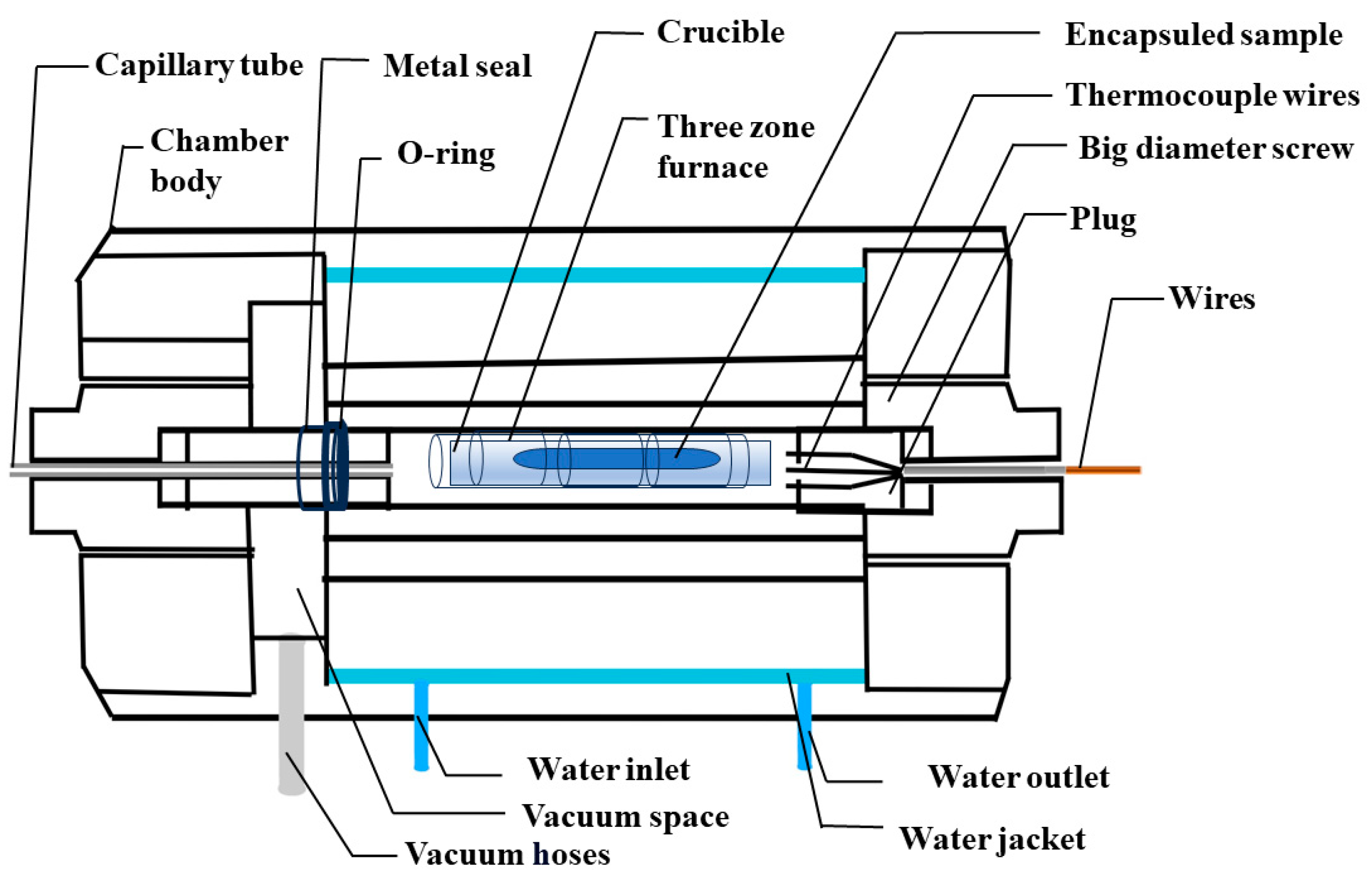
(i) High-Pressure chamber: The high-pressure chamber body is a central component, depicted in
Figure 5, and is constructed from robust steel to withstand extremely high pressures. Its intricate design ensures that this camber remains impervious to leaks even under high-pressure conditions, ensuring a safe environment for high-pressure growth. To regulate temperature efficiently, the outer jacket of the chamber is integrated with a water cooling system with a water inlet and outlet. The water cooling system plays a vital role in maintaining the temperature of the pressure chamber body and ensuring its safe operation under high-temperature and high-pressure conditions. One side of the chamber is precisely connected to a capillary using a big-diameter screw, supported with O-rings and additional seals, ensuring a completely leak-free chamber. This capillary tube serves a dual purpose, functioning as both the inlet and outlet for gas, and is connected to the compressor and gas bottle. On the opposite side, a sample holder with a high-quality O-ring and metal seal facilitates the insertion of samples into the pressure chamber, and a big-diameter screw provides crucial support to secure plugs, which contain numerous components within the chamber as shown in
Figure 5. Typically, we flush the chamber at least three times before initiating any growth processes. However, in some cases, the sample is highly sensitive to moisture and oxygen, so we employ a vacuum space to create a vacuum environment within the chamber and heat the entire chamber to a temperature of about 100 °C to eliminate any remaining oxygen and moisture. Within the sample holder, a variety of thermocouples are employed to monitor the temperature at different sections of the chamber precisely. Moreover, the plugs are the central hubs for all electrical connections, including heater wires, thermocouples, and pressure gauges, ensuring seamless operation and integration while securely eliminating any possibility of leakage risk. Reliability and security are ensured for the entire system by connecting these wires to the control unit and monitor. The chamber’s adaptability for single, double, or triple zone furnaces is a noteworthy feature, enhancing its utility for growing high-quality single crystals and facilitating a wide range of experiments in materials science.
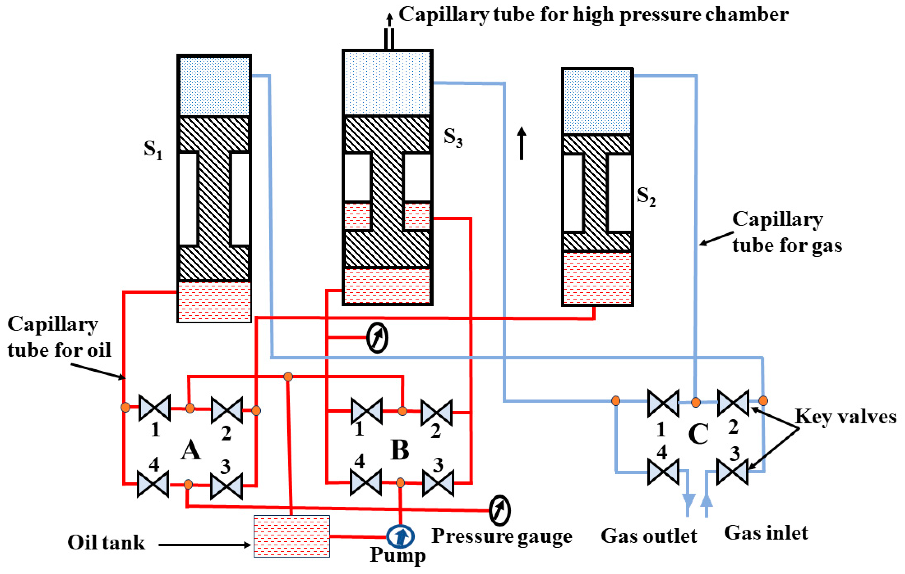
(ii) Compressor: The compressor is an oil-based system with a three-stage piston configuration and a pump, as shown in
Figure 6. The piston moves upward to create gas pressure. Generally, this pump is connected to all the stages and moves the piston upward to create high pressure. The systematic block diagram is shown in
Figure 6, and the list of maximum pressures for different stages is mentioned in
Table 1. In the first stage (S
1), it can generate pressure up to 800 bar. The second piston (S
2) can achieve pressures of up to 4000 bar, and in the final stage (S
3), it can reach an impressive pressure of up to 1.8 GPa (18,000 bar). This three-stage piston setup allows for the precise control and adjustment of pressure from low to very high, which is one of the notable strengths of our compressor. The presence of 12 key valves is the most intricate and critical aspect of the compressor, as shown in
Figure 6, which plays a pivotal role during the gas compression process and ensures precise and controlled pressurization. The basic principle of the pump is already explained above.
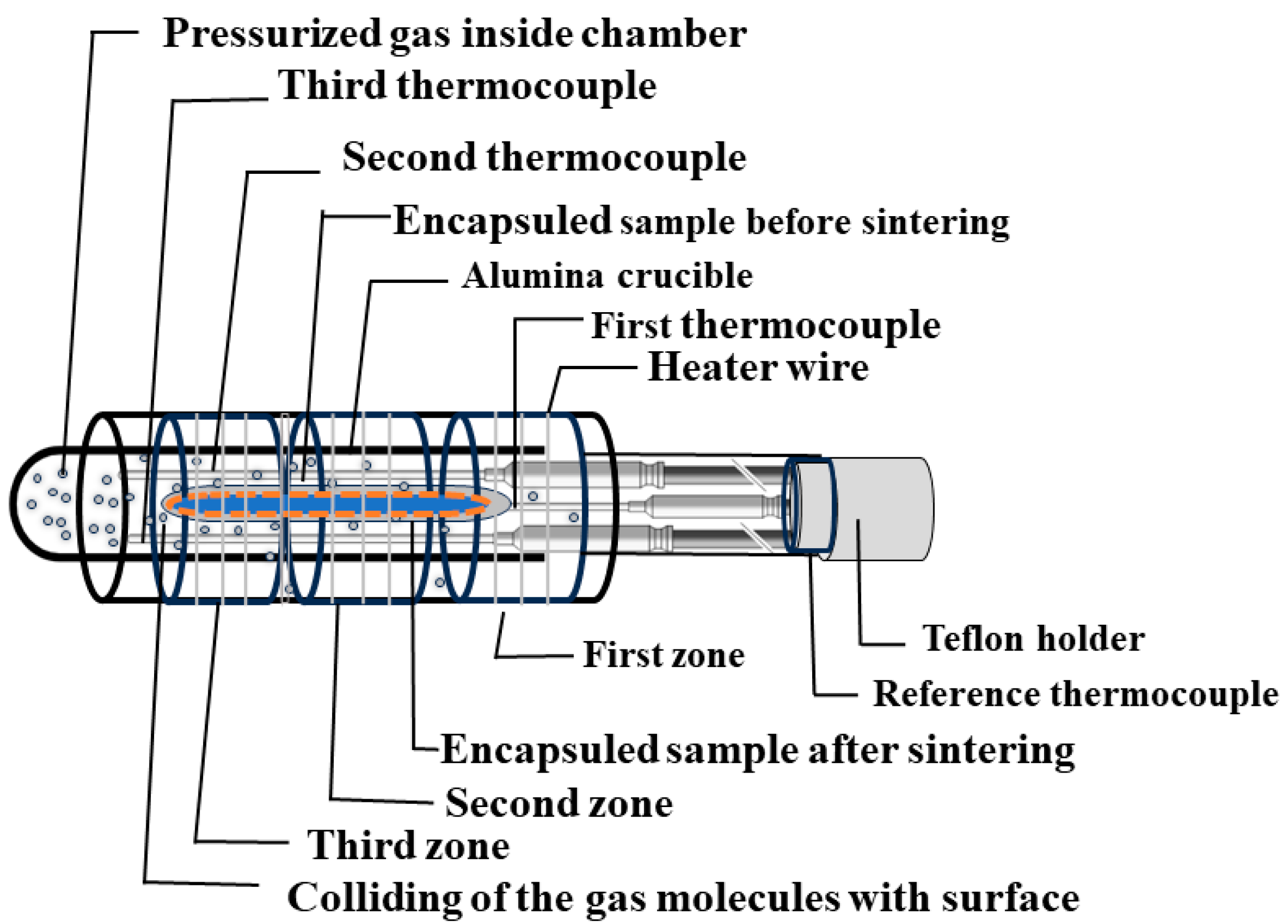
(iii) Sample holder with furnace: This component contains a wide setup, consisting of essential components like the sample container, furnace, thermocouples, and pressure gauge. A systematic block diagram is shown in
Figure 7. The sample container, designed either in a boat or cylindrical form with a secure cap, acts as the vessel for keeping the samples inside the high-pressure chamber. The furnace is equipped with a Kanthal (FeCrAl alloy) heater wire capable of reaching temperatures up to 1100 °C under high pressure for a long time. When higher temperatures are needed, molybdenum (Mo) wires can be utilized, through which the maximum temperature can reach up to approximately 1700 °C within this high-pressure chamber [
3], as listed in
Table 2. Furthermore, either a single or multi-zone furnace can be used, as shown in
Figure 7, to create the high temperature. However, a three-zone, or multi-zone, furnace is typically employed to establish temperature variations during the sample growth process. The length of the heater is around ~15 cm, and a thermal gradient in one zone furnace can be observed in the range of 10 °C to 30 °C at the top and bottom of the chamber compared to the center part of the chamber.
For accurate temperature monitoring, three thermocouples are employed, in addition to a reference thermocouple that provides precise temperature readings across all zones. We can use various kinds of thermocouples according to the temperature range, as mentioned in
Table 3. The plug tip’s temperature is typically monitored with T-type thermocouples made of copper and constantan, commonly used as a reference thermocouple, where its temperature variation up to 50–70 °C is a common practice to ensure the safety of plug connections and suggests a good performance of the experiment during high-temperature and high-pressure conditions within the sample holder. Typically, K-type thermocouples made of chromel and nickel-aluminum, are used for three thermocouples that are placed at the bottom, center, and top positions of the sample holder. We generally use these sensors to monitor the temperature up to 1100 °C. For high temperatures ranging from 1100 °C to 1700 °C, B-type thermocouples made of platinum and rhodium are used in a similar way. However, various thermocouples can be selected based on specific requirements [
3,
16]. The actual pressure inside the chamber is regularly monitored using pressure gauges. These vital components, including the thermocouples, heaters, and gauges, are seamlessly connected to the controller unit and monitor, ensuring precise control and monitoring of the high-pressure chamber’s conditions. Modifying this chamber according to specific material growth conditions adds to its versatility and suitability for diverse research and experimentation needs in materials science.
(iv) Controller unit and monitor: The final component of HP-HTS comprises a temperature controller and a pressure gauge, both of which can be connected to a computer for enhanced functionality. This capability allows for the real-time monitoring of temperature and pressure within the system. The temperature controller facilitates the monitoring of all four thermocouples, each positioned at different locations within the system. One of these thermocouples also serves as a reference temperature point, enabling precise temperature measurements near the sample. This feature provides valuable insights into the actual temperature conditions during experiments. Through the interface with the computer, the pressure gauge provides real-time data on the pressure inside the chamber. This allows for continuous monitoring and control, ensuring that pressure conditions are maintained as required for specific experiments.
4. Current Results Using this HP-HTS Facility
Currently, we are applying this HP-HTS technique for FBS [
17,
18], which has the highest
Tc of 58 K, a high upper critical field (
Hc2) of 100 T, and a high critical current density (
Jc) of 10
7–10
8 A/cm
2 at 5 K [
19]. These properties make them a strong contender for practical applications [
20]. Many compounds belonging to this high
Tc superconductor can be categorized into six families, of which 1111 (
REFeAs(O,F),
RE = La, Ca, Pr, Gd) as a doped family and 1144 (
AeAFe
4As
4;
Ae = Ca;
A = K) as a stoichiometric family provide the highest
Tc of 58 K [
21] and 36 K [
22], respectively, for FBS. Hence, our current focus is on the growth process of 1111 and 1144 families using the HP-HTS technique [
15]. Before using the high-pressure technique for these complicated families, the HP-HTS technique was applied to the simplest FBS, i.e., the 11 (FeSe) family. Tellurium (Te) doping at Se-sites, i.e., Fe(Se,Te), provides the highest transition temperature
Tc of 15 K for FeSe
0.5Te
0.5 [
23]. First, we synthesized the high-quality Fe(Se,Te) sample by the solid-state reaction method at ambient pressure (0 GPa). The selected composition FeSe
0.5Te
0.5 is prepared at 600 °C for 21 h in the first step, and in the second stage, the sample is grounded and heated again at 600 °C for 4 h, as more detail was discussed in our previous studies [
12,
23]. This FeSe
0.5Te
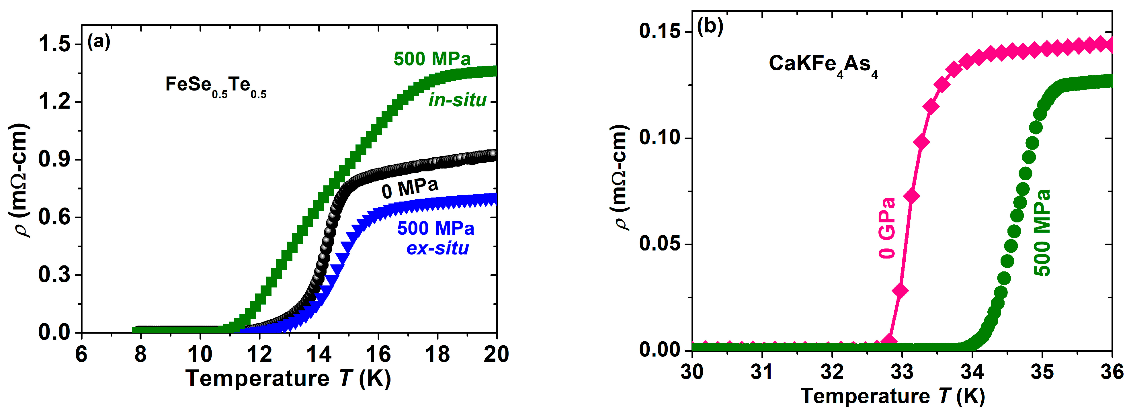
0.5 sample shows the transition temperature up to 15 K by the convenient synthesis method at ambient pressure, as reported by the previous report [
23] and depicted in
Figure 8a.
To understand the high-pressure growth effect, Fe(Se,Te) bulks are prepared in a very broad pressure range from 0 GPa to 1 GPa at 600 °C for 1 h and 11 h, as reported in our previous study [
12]. Also, these samples were prepared by in-situ and ex-situ processes and were sealed in a Ta-tube or placed in an open Ta-tube. These various conditions were used to optimize the best growth conditions so that a high-quality sample could be produced with high superconducting properties. Interestingly, the optimized conditions were obtained at 600 °C, 1 h, and 500 MPa, where samples show the highest superconducting properties [
12]. The comparative graph is shown in
Figure 8a. Our studies also confirm that grain connectivity can be improved by having the pure superconducting phase when the samples are sealed into a Ta-tube under an argon gas atmosphere through an ARC melter, whereas the samples placed in an open Ta-tube have a pure superconducting phase, but the grain connectivity is poor due to the high gas pressure passing through the micro- or nanopores. Fe(Se,Te) bulks prepared by the optimized conditions are depicted in
Figure 8a, which shows the high superconducting transition (
Tc = 17 K) compared to the samples prepared by the ambient pressure method (
Tc = 15 K). These optimized study processes confirm that the high gas pressure technique can be an effective method to enhance the superconducting properties, and the synthesis process can be completed in a very short reaction time under the optimized growth pressure [
12].
After having a good experience with this 11 family of FBS, we have started to work with CaKFe
4As
4 (1144) which is a stoichiometric compound of FBS [
15,
24]. On the basis of the optimization of the 11 (FeSe
0.5Te
0.5) family, we have prepared 1144 samples under the optimized conditions (500 MPa, 1 h) at 500 °C. Interestingly, CaKFe
4As
4 prepared by HP-HTS has enhanced the superconducting transition by ~2 K with improved sample quality compared to the 1144 bulks prepared under the conventional synthesis method [
15] at ambient pressure. The resistivity measurements of these samples are depicted in
Figure 8b, which clearly enhances the
Tc value with a sharp transition. It suggests that the 1144 bulk prepared by HP-HTS has homogeneous and well-connected grain boundaries. In a similar way, we are also applying this HP-HTS to other members of the 1144 and 1111 families.


