Article

Writer Performance Optimization with Shingled Rounded Corner and Exchange Coupled Composite Media

1
School of Mathematics and Computer Science, Gannan Normal University, Ganzhou 341000, China
2
Key Laboratory of Jiangxi Province for Numerical Simulation and Emulation Techniques, Gannan Normal University, Ganzhou 341000, China
3
School of Economics and Management, JiangXi University of Science and Technology, Ganzhou 341000, China
*
Author to whom correspondence should be addressed.
Crystals 2022, 12(9), 1261; https://doi.org/10.3390/cryst12091261
Submission received: 7 August 2022 / Revised: 26 August 2022 / Accepted: 2 September 2022 / Published: 6 September 2022
(This article belongs to the Special Issue Magnetic and Magnetoelectric Materials and Devices)

Abstract

:
The shingled magnetic recording (SMR) with exchange coupled composite (ECC) media is a feasible method to achieve the areal density of multi-Tera-bit/in2. However, a rounded corner is inevitable due to deviations from the fabrication process of a shingled writer. The rounded corner is modeled and characterized by two parameters: the rounded angle (θ) and the corner length (L). This paper investigates the influence of the rounded corner effect on the field distribution, writing capability, bit error rate (BER), and erase band width (EBW) of SMR. The analysis suggests that an optimized structure of rounded corner can increase the write field gradient and reduce the stray field to avoid adjacent track encroachment. The results show that if the shingled rounded corner writer with θ = 40° and L = 3 nm is elaborately constructed, the write field gradient can attain a peak value of 552 Oe/nm, and the write performance of the recording system can be improved.

1. Introduction

When magnetic recording storage reaches ultra-high areal density, the recording media requires a larger anisotropy energy density (due to the smaller volume of each grain) to maintain thermal stability, and the writability needs to be enhanced to reverse the recording grain with a high anisotropy energy barrier, one of the feasible methods is to apply a shingled magnetic recording with ECC media [1,2,3]. The shingled magnetic recording technology has been applied in the manufacture of commercial hard drives. Currently Western Digital and Seagate companies have both launched the commercial hard drives based on shingled magnetic recording technology. Compared with conventional media, ECC media greatly decreases the switching field while maintaining almost the same thermal stability [4]. Composite media consists of a hard/soft magnetic bilayer structure, the hard layer with high anisotropy providing thermal stability while the soft layer with low anisotropy helps to switch the hard layer during the writing process, and it works through the quantum mechanical exchange coupling among magnetic layers [5,6,7,8]. Meanwhile, it is known that shingled magnetic recording utilizes the pole tip with a relatively large write corner to switch recording bits, thus the write corner plays an important role in the write performance. However, the rounded corner is inevitable in the manufacturing process for the main pole of a shingled writer [2]. The write performances of a rotated single sense head and normally oriented single head with two-dimensional magnetic recording systems were investigated [9]. The multi-track detection scheme with a two-dimensional hybrid equalizer was developed to mitigate the impact of inter-track interference and media noise on the bit error rate performance [10]. The four-reader array detection architecture was proposed to recover the shingled recording data [11]. The novel read channel was modeled to capture the effects of inter-track and inter-symbol interference, and the neural network block predictor was presented to recover the recording information [12]. This research studies the effect of a shingled rounded corner writer on the write performance of SMR, which provides a guiding role on improving the writer design to reduce the erase band width.
Figure 1a shows the 3D model of a shielded shingled rounded corner writer. Figure 1b shows the rounded corner from the air-bearing surface (ABS) view. As shown in Figure 1c, the rounded corner is characterized by two parameters in the model of a shingled rounded corner writer: the rounded angle (θ) and corner length (L). The study indicates that during the writing process, the influence of a rounded corner causes the fluctuation of head field distribution around the write corner. Different structures of rounded corners cause variations of field gradients along the cross-track direction, which may lead to adjacent track erasure (ATE).
This paper explores the impact of rounded corner writer design on the write performance of SMR with ECC media. First, the effect of writer structure on the write performance was investigated to reach a trade-off between adequate writability and field gradient. Specifically, the influence of the rounded corner effect on the write performance was evaluated by considering the variation of the write field gradient, the write-in error rate, and the erase band noise. Additionally, the EBWs of single-phase and ECC media were also studied and compared using the proposed EBW calculation method [13]. Furthermore, the influence of shield gap on the EBW was also discussed in this paper. Such an optimized shingled writer structure with a rounded corner was found to increase the field gradient and avoid the stray field-induced track erasure, which improves the write performance.

2. Model Parameters and Methodology

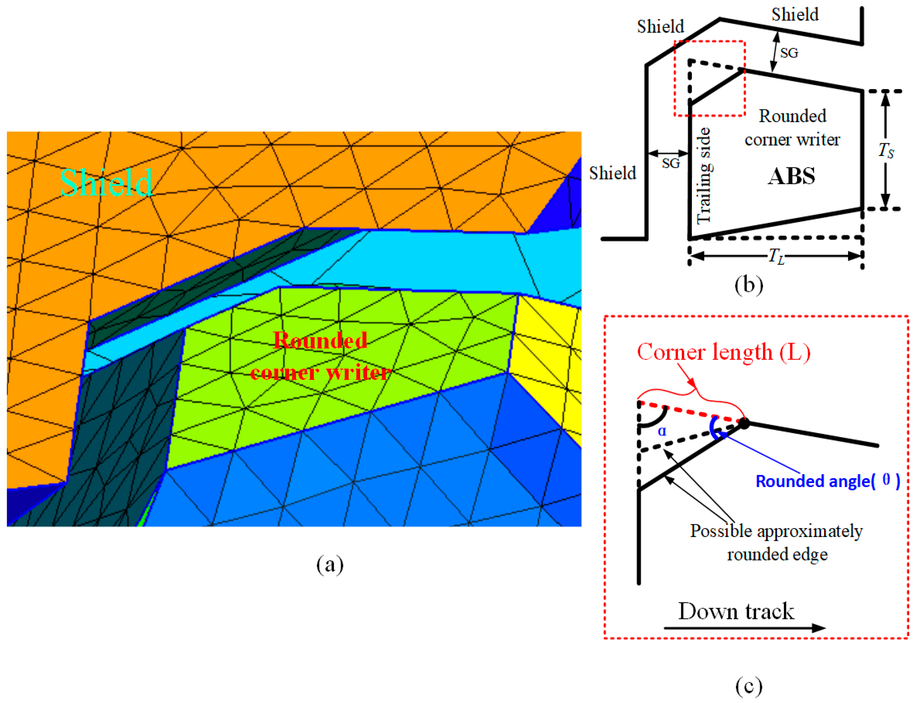
2.1. Design of Trapezoidal Shingled Writer

The experimental model applies the frequently used trapezoidal shingled writer to investigate the rounded corner effect. The shingled writer consists of a tapered pole tip, return yoke, half wrap-around shield, and soft magnetic underlayer (SUL) which functions as a mirror for the shingled writer to increase the field gradient. The finite element micromagnetic method (FEM) is introduced to mesh the shingled writer into tetrahedral elements [14], and the edge length of pole tip part is 1 nm, which is sufficient to emulate the relaxation process of the magnetic writer. The height of the pole tip is 80 nm. The write corner angle (α) and tip tapered angle are set as 78° and 45°, respectively. The height of the half wrapped-around shield is 15 nm and the shield tapered angle is 30°. The width of the narrow end (Ts) and the length (TL) of the pole tip (shown in Figure 1b) are set as 14 nm and 34 nm, respectively. The writer-media spacing is maintained at 5 nm. During simulation, the shingled rounded corner writer with various rounded angles (θ), corner lengths (L), and shield gaps (SG) are designed to analyze the effect of the rounded corner on the write performance. The detailed structure of the shingled writer was discussed in our previous work [13].
The magnetic parameters of the shingled writer are set as follows according to [13,15]: the saturation magnetization (Ms), exchange coupling constant and anisotropy constants (Ku) of the main pole are 1910 emu/cm3, 1.0 × 10⁻⁶ erg/cm and 3 × 10⁴ erg/cm3, respectively. The shield is half wrapped around to produce a steeper field gradient in the cross-track direction. The Ms of shield is 800 emu/cm3, the exchange coupling, and Ku are the same as the shingled writer. The damping factor is 0.1 for the recording simulation. The width of the tip broad end (Tw) is varied to obtain reasonable writing capability of the shingled writer.
Figure 2 shows the effective write field and field gradient as a function of the width of the tip broad end (Tw) without a rounded corner. As illustrated, the effective write field increases as the width becomes longer, but it reaches a comparatively large value and grows slowly if the width exceeds about 48 nm. The effective write field does not grow unrestricted with the increasing width. This is because the effective write field is mainly determined by the writing corner in the SMR system, and when the width is larger than a certain value (i.e., 50 nm in our simulation), the newly added portion of the pole tip is further away from the writing corner, which makes the impact of the write field negligible. The write field gradient peaks at the width of 40 nm, which avoids ATE and reduces the bit error rate of adjacent tracks. In this situation (Tw = 40 nm), the effective write field is 17.6 kOe and the maximum field gradient is 470 Oe/nm.

2.2. Magnetic Configuration of ECC Media

Compared with the conventional perpendicular media, the ECC media effectively decreases the switching field without a loss in thermal stability. The ECC media structure increases the writability for the shingled writer, which reaches a trade-off between adequate write field and manufacture of the shingled writer. The ECC media is modeled from Voronoi grains with an average diameter of 5 nm, targeting an areal density of 20 T grains per square inch. Each grain consists of a two-layer composite structure, the top layer is the soft magnetic layer, and the bottom layer is the hard magnetic layer. The thickness of the seed layer between the two-layer composite structures is 2 nm.
The average relaxation time τ is calculated as a function of the energy barrier ΔE of ECC magnetic grain according to the Neel–Arrhenius equation [4].
1 / τ = f 0 e Δ E / k B T
where kB is Boltzmann constant, T is working temperature (T = 350 K), and the thermal attempt frequency f0 of two spin model for composite media is set as 1.3 × 10¹² Hz for ultra-high recording density [4]. Here, the thermal stability factor (ΔE/kBT) is set as 60, aiming at the relaxation time of more than 10 years in the working environment. The energy barrier (ΔE) as mentioned in [16] is given by
Δ E = ( K u h V h + K u s V s ) ( 1 H H s w ) γ
where Ku is the anisotropy constant of soft (index s) and hard (index h) layers, V is the volume, H is the writer field and Hsw is the switching field, γ equals 1.5.
In the micromagnetic simulation, L10-FePt is used for the hard layer of ECC media due to its high magnetocrystalline anisotropy which could provide sufficient thermal stability [17], and [Co/Ni]5 is chosen as the soft layer materials, which helps to overcome the limitation of the current magnetic writing field. The magnetic parameters are set as follows according to [13,18,19]: Ku are set as KFePt = 1.61 × 10⁷ erg/cm3 and K[Co/Ni]5 = 2.5 × 10⁶ erg/cm3, while the thicknesses of hard and soft layers are set to 6 nm and 4 nm to keep ΔE = 60kBT, respectively. Ms is set to MFePt = 500 emu/cm3 and M[Co/Ni]5 = 750 emu/cm3. The exchange coupling constants are set as AFePt = 1.2 × 10⁻⁶ erg/cm and A[Co/Ni]5 = 1.0 × 10⁻⁶ erg/cm; the interlayer exchange coupling constant Aex between hard and soft phases is assumed to be 1.1 × 10⁻⁶ erg/cm. The switching field of FePt(6 nm)/[Co/Ni]5(4 nm) is 16.44 kOe according to our simulation.
The erase band width is not only determined by the write field, but also by the media geometric, magnetic properties, etc. The EBW calculation is applied to continuous magnetic recording media for evaluating the erase band noise. The EBW calculation method provides a fast evaluation criterion for the write performance, which can account for the effects of the rounded corner and adjacent track erasure. For comparison, the EBW as a function of skew angle is investigated for the single-phase media [Co/Ni]5(10 nm) and ECC media FePt(6 nm)/[Co/Ni]5(4 nm) with the same thickness. As illustrated in Figure 3, the minimum and maximum EBW of FePt/[Co/Ni]5 are 8.1 nm and 15.8 nm, respectively. In contrast, the EBW of ECC media is far superior to the corresponding EBW of 54.8 nm and 55.5 nm for the single-phase media [Co/Ni]5. Meanwhile, the EBW of the single-phase media varies insignificantly with the increase of skew angle. Because the switching field of [Co/Ni]5 (about 6.8 kOe) is much smaller than that of FePt/[Co/Ni]5 with the same thickness. The corresponding recording position is far away from the shingled writer, where the skew effect becomes insignificant.

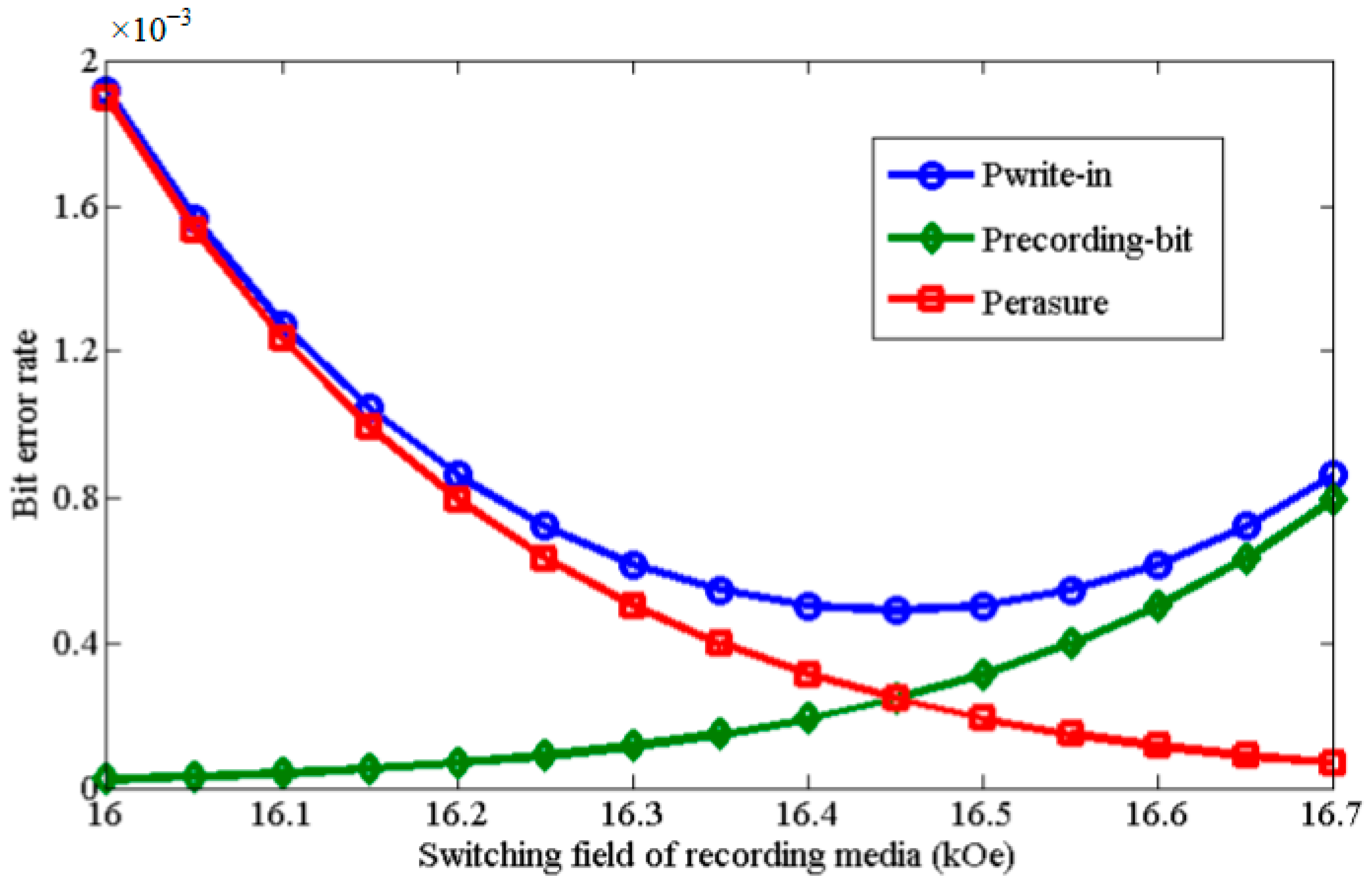
2.3. Combined Write-In Error Probability

The combined write-in error probability (Pwrite-in) is one of the evaluation criteria for the write performance. The Pwrite-in is defined as the rate that the adjacent track bit is erased (Perasure) and the current recording bit is not reversed (Precording_bit) when writing the current bit, which can be expressed by
P w r i t e i n = 1 ( 1 P e r a s u r e ) × ( 1 P r e c o r d i n g _ b i t )
Assuming that the statistical deviation is Gaussian distribution, the Perasure and Precording_bit are given according to [13,20].
P e r a s u r e = 0.5 × ( 1 e r f ( H s w H max _ A T E σ H 2 ) )
P r e c o r d i n g _ b i t = 0.5 × ( 1 e r f ( H r e c o r d i n g H s w σ H 2 ) )
where Hsw is the switching field of recording media, Hmax_ATE is the stray field of adjacent bit, Hrecording is the writing field strength, σH, σH′ are the combined field variance of the adjacent bit and recording bit, respectively. The recording noise is mainly caused by three aspects, including: (1) writer synchronization, (2) intrinsic switching field distribution and demagnetizing field from the neighboring grains, and (3) cell spacing or size deviation. When the shingled writer moves across the recording bits along the down track direction and switches the media polarity, the adjacent track’s bits could be potentially erased by the stray field. The combined field variance consists of 5% writer synchronization variance (σtime), 3.5% grain anisotropy field distribution and demagnetizing field from neighboring grains (σsw), and 15% grain size deviation (σjitter). Considering the recording noise discussed above, σH and σH′ can be obtained by the quadratic sum of the three field variances.
The switching field of the recording media (Hsw) is a critical factor affecting the BER. It needs to be ensured that Hsw is much smaller than the writing field (Hrecording) to reverse the recording bit with a high possibility, and larger than the maximum adjacent track erasure field (Hmax_ATE) to avoid the potential reverse of adjacent bits. Figure 4 shows how the switching field affects the write performance. As illustrated, the combined write-in error probability (Pwrite-in) is sensitive to the switching field. A small dispersion of Hsw can lead to an abrupt change in BER. As mentioned in Equation (3), the smaller Hsw makes the recording bit be reversed more easily, and increases the erasure possibility of the adjacent track bit. The Perasure drops sharply along with the increase of Hsw when Hsw is smaller than 16.44 kOe, so the Pwrite-in declines as well. In contrast, because the Precording_bit increases rapidly along with the increase of Hsw when Hsw is larger than 16.44 kOe, the Pwrite-in increases correspondingly. The results show that proper Hsw is significant to guarantee the writing capability of the shingled writer, and simultaneously the media polarity can avoid being potentially switched by the stray field at the same write window. Therefore, L10-FePt(6 nm)/[Co/Ni]5(4 nm) (Hsw = 16.44 kOe) is adopted as an appropriate ECC media to calculate EBW and the combined write-in error rate.

3. Results and Discussion

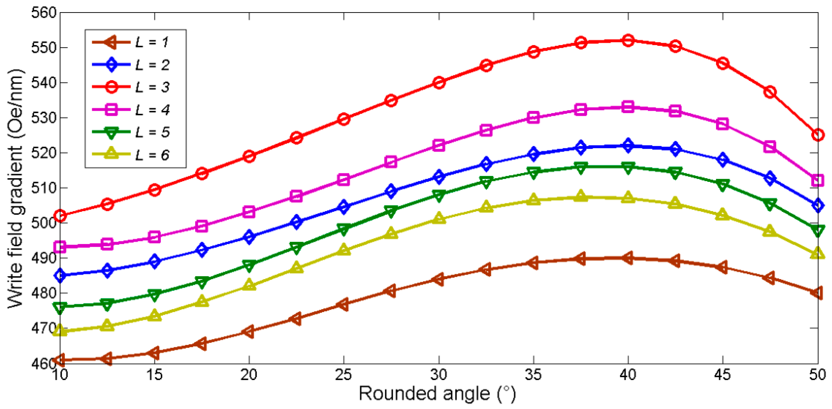
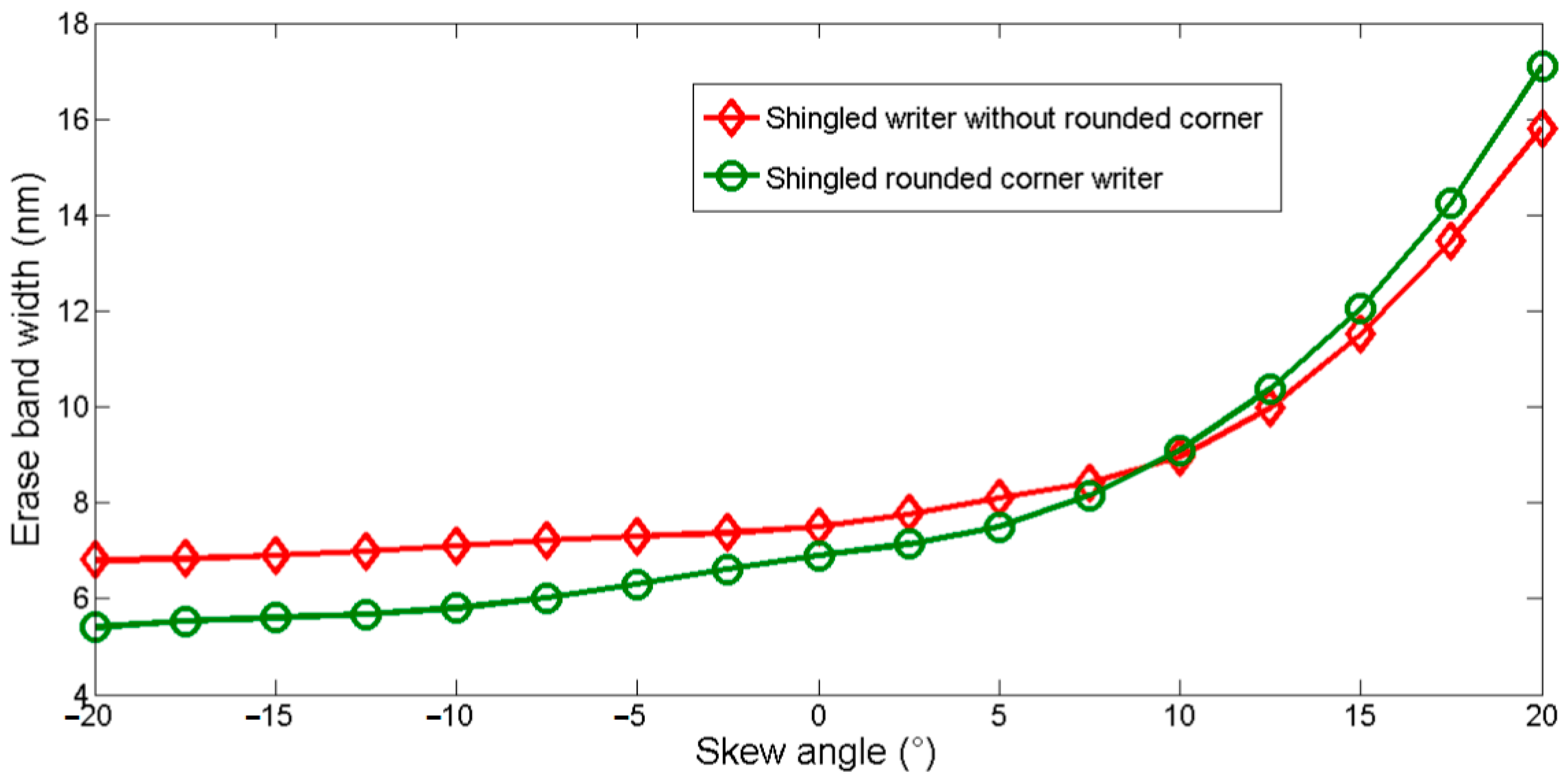
3.1. The Rounded Corner
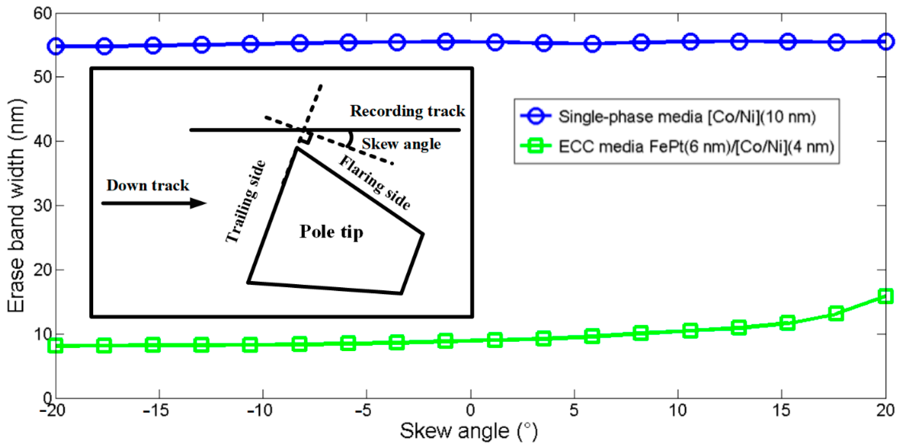
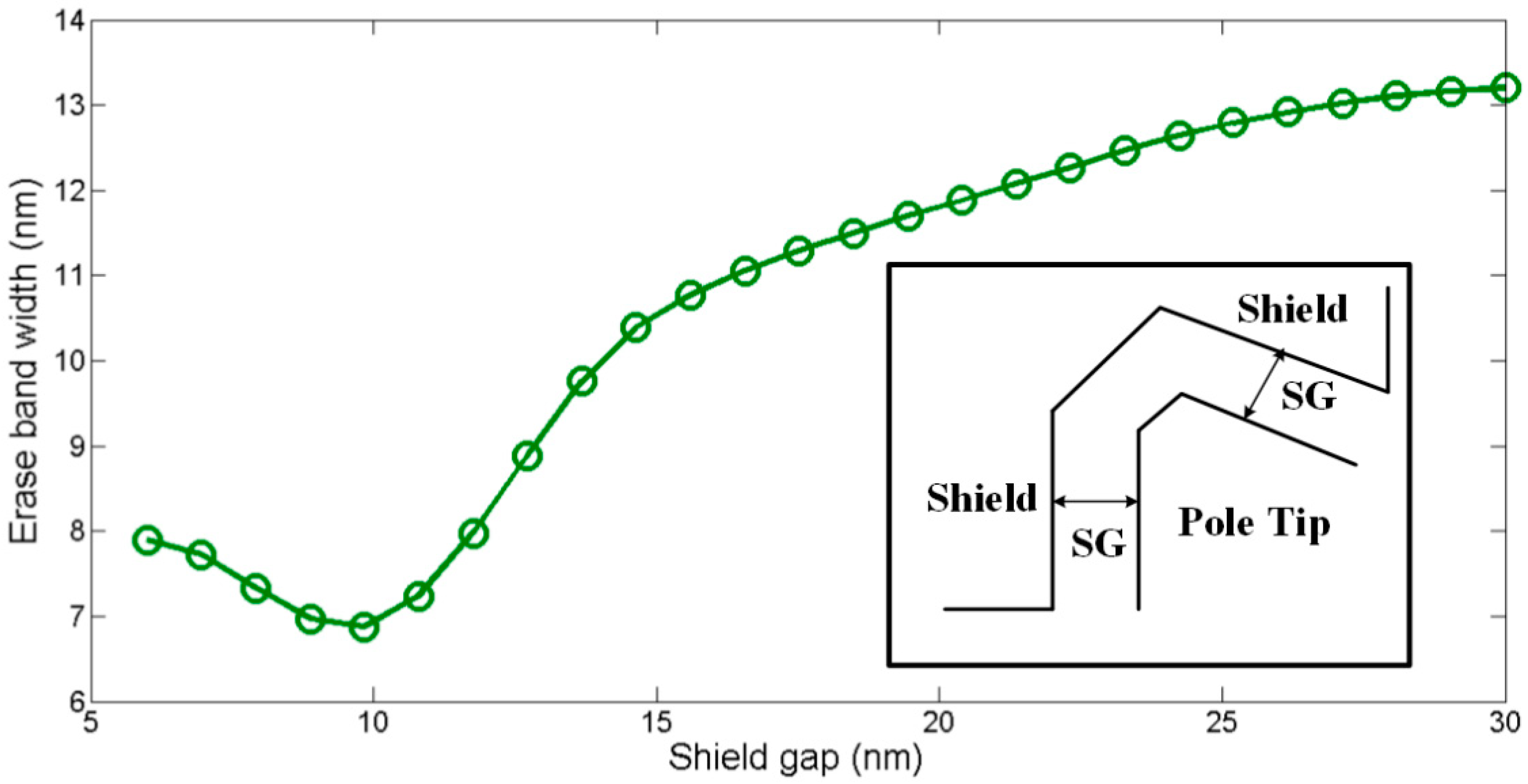
The rounded corner writer is modeled as shown in Figure 1c. The shape of the rounded corner is characterized by the rounded angle (θ) and corner length (L). The rounded corner greatly influences the field distribution of the shingled writer and also changes the field gradient at the writing corner. A tiny loss of the tapered structure caused by manufacturing deviation may have little influence on the edge field to recording bit, but it could cause the fluctuation of the stray field and thus lead to adjacent track erasure. Therefore, the parameter θ and L are varied to generate different rounded corner structures to analyze their impact on the write performance of the recording system.
The tip broad end width of the shingled writer is fixed as 40 nm according to Figure 2. θ is ranged from 10° to 50°, and L varies from 1 nm to 6 nm to construct different rounded corner shapes. The write field gradient changes with different θ and L, which is shown in Figure 5. As illustrated, the shingled rounded corner writer can attain the maximum field gradient when L is 3 nm, and the field gradient peaks when the rounded angle is 40° for all corner length cases. The larger field gradient results in a larger field margin, which is the difference between the write field of recording cells and the erasing field of adjacent track erasure cells. As a result, the peak of field gradient is about 552 Oe/nm (with θ = 40° and L = 3 nm). In this case, the field margin is the largest, which helps to reduce the possibility of erasing neighboring cells and avoiding adjacent track encroachment. It is worth noting that a larger field gradient results in a smaller ATE field, which is most affected by the writer stray field and determines the bit error rate of the adjacent track. Thus, the maximum field gradient in cross-track direction is calculated to avoid track erasure and attain a better write performance.
Figure 6 shows the combined write-in error probability versus different rounded corner cases. As illustrated, a moderate corner length (L = 3 nm) is recommended to achieve a satisfactory system BER. Furthermore, a relatively large rounded angle (θ = 40°) is helpful to achieve the lowest combined write-in error rate. According to the calculation, the combined write-in error rate of L = 3 reduces by 31% compared with that of L = 1 nm when θ = 40°. The recording system achieves the best write performance at θ = 40° and L = 3 nm with the combined write-in error rate of 3.9 × 10⁻⁴. Meanwhile, the BER of the recording cell and the adjacent cell are Precording_bit = 1.4 × 10⁻⁴, Perasure = 2.5 × 10⁻⁴, respectively.
Figure 7 compares the skew angular dependence of EBW between a normal shingled writer and a rounded corner writer (θ = 40° and L = 3 nm). The results show that the EBW increases with the skew angle, and the EBW of the rounded corner writer is smaller than the normal writer when the skew angle increases from −20° to 8°, because the effective write field with a rounded corner is slightly smaller than the normal writer. Meanwhile the write field gradient with rounded corner decreases more sharply than the normal writer when the skew angle is greater than 8°, which brings a severer fringing field, and correspondingly the EBW of the rounded corner writer increases more sharply.

3.2. The Shield Gap

The shield is usually used to increase the field gradient, which also affects EBW. The shield gap (SG) is an important structure parameter of the writer design for the write performance. In the simulations, the corresponding EBW changes as a function of SG increase from 5 nm to 30 nm are shown in Figure 8. It is observed that EBW decreases from the initially 7.9 nm to its minimum value of 6.9 nm as SG increases from 6 nm to 10 nm, and then the EBW increases sharply when SG further increases. However, when SG is larger than 25 nm, the EBW increases slowly because the shielding effect is rather weakened. This indicates that overlarge SG damages the field gradient, while excessively small SG greatly decreases the effective write field, which are both detrimental to improving the track density and the write performance. Hence, a half wrap-around shield with a proper shield gap similar to the track pitch should be advantageous to reduce the erase band noise and ATE.

4. Conclusions

This paper explored the rounded corner effect on the write performance of the shingled magnetic recording system with ECC media, targeting the areal density of 20T grains/in2. The rounded corner is modeled for various structures and characterized by two parameters: rounded angle and corner length. The field gradient at the writing corner is analyzed for various structures of the rounded corner. The combined write-in error rate and EBW are taken into consideration to evaluate the performance of the recording system. The recording system achieves the best write performance at θ = 40° and L = 3 nm with a combined write-in error rate of 3.9 × 10⁻⁴. The EBW increases with the skew angle, and the EBW of the rounded corner writer is smaller than a normal writer when the skew angle increases from −20° to 8°. To maintain a large write field gradient, a skew angle no more than 8° is suggested. The recording system can avoid track erasure induced by shingled stray field and narrower tracks, hence achieving a higher track density of shingled magnetic recording.

Author Contributions

Conceptualization, G.X.; funding acquisition, G.X.; methodology, G.X.; investigation, G.X. and Y.W.; writing—original draft preparation, G.X.; writing—review and editing, G.X. and Y.W. All authors have read and agreed to the published version of the manuscript.

Funding

This research is supported by the Project of Science and Technology of Education Department of Jiangxi Province (Grant No. GJJ211407), the Tendering Project for the Key Laboratory of Jiangxi Province for Numerical Simulation and Emulation Techniques (Grant No. 21zb02), the National Natural Science Foundation of China (Grant No. 62166001), the Project of Jiangxi Provincial Natural Science Foundation (Grant No. 20202BAB202010), the Science and Technology Program of Jiangxi Province (Grant No. 20192BCB23019, Grant No. 20202BBE53024), the Jiangxi Double Thousand Plan (Grant No. jxsq2019201061), and the Science and Technology Innovation Talent Program of Ganzhou.

Institutional Review Board Statement

Not applicable.

Informed Consent Statement

Not applicable.

Data Availability Statement

Not applicable.

Conflicts of Interest

The authors declare no conflict of interest.

References

  1. Wood, R.; Williams, M.; Kavcic, A.; Miles, J. The Feasibility of Magnetic Recording at 10 Terabits Per Square Inch on Conventional Media. IEEE Trans. Magn. 2009, 45, 917–923. [Google Scholar] [CrossRef]
  2. Kanai, Y.; Jinbo, Y.; Tsukamoto, T.; Greaves, S.J.; Yoshida, K.; Muraoka, H. Finite-Element and Micromagnetic Modeling of Write Heads for Shingled Recording. IEEE Trans. Magn. 2010, 46, 715–721. [Google Scholar] [CrossRef]
  3. Wang, Y.; Xu, Y.; Chen, Y.; Lv, N.; Wen, Y.; Li, P. Improved Recording Performance with Writer Design and Joint Learning-Based Neural Network for Heat-Assisted Interlaced Magnetic Recording. IEEE Trans. Magn. 2021, 58, 3100608. [Google Scholar] [CrossRef]
  4. Shen, X.; Kapoor, M.; Field, R.; Victora, R.H. Issues in Recording Exchange Coupled Composite Media. IEEE Trans. Magn. 2007, 43, 676–681. [Google Scholar] [CrossRef]
  5. Victora, R.H.; Xiao, S. Exchange Coupled Composite Media. Proc. IEEE 2008, 96, 1799–1809. [Google Scholar] [CrossRef]
  6. Sohn, H.; Victora, R.H. Recording Comparison of ECC versus Conventional Media at Equal Grain Size. IEEE Trans. Magn. 2011, 47, 4073–4076. [Google Scholar] [CrossRef]
  7. Makarov, D.; Lee, J.; Brombacher, C.; Schubert, C.; Fuger, M.; Suess, D.; Fidler, J.; Albrecht, M. Perpendicular FePt-based exchange-coupled composite media. Appl. Phys. Lett. 2010, 96, 485. [Google Scholar] [CrossRef]
  8. Richter, H.J.; Choe, G.; Terris, B.D. Recording Behavior of Exchange Coupled Composite Media. IEEE Trans. Magn. 2011, 47, 4769–4774. [Google Scholar] [CrossRef]
  9. Wang, Y.; Erden, M.F.; Victora, R.H. Study of Two-Dimensional Magnetic Recording System Including Micromagnetic Writer. IEEE Trans. Magn. 2014, 50, 3002405. [Google Scholar] [CrossRef]
  10. Xu, Y.; Wang, Y.; Li, Y.; Chen, L.; Li, P. Multitrack Detection with Two-Dimensional Hybrid Equalizer for High-Density Bit-Patterned Media Recording. IEEE Magn. Lett. 2020, 11, 6505505. [Google Scholar] [CrossRef]
  11. Wang, S.; Chen, J.; Luo, K.; Xie, G.; Lu, P.; Cheng, W. Joint Four-Reader Array Equalization and Detection for a Single Track in TDMR. IEEE Trans. Magn. 2019, 55, 3002006. [Google Scholar] [CrossRef]
  12. Luo, K.; Wang, S.; Xie, G.; Chen, W.; Chen, J.; Lu, P.; Cheng, W. Read Channel Modeling and Neural Network Block Predictor for Two-Dimensional Magnetic Recording. IEEE Trans. Magn. 2019, 56, 6700805. [Google Scholar] [CrossRef]
  13. Chen, J.; Xie, G.; Luo, K.; Wang, S.; Ping, L.; Wang, Y. Study of Erase Band and Write Performance for Shingled Magnetic Recording With FePt-Based Exchanged Coupled Composite Media. IEEE Trans. Magn. 2018, 54, 7100306. [Google Scholar] [CrossRef]
  14. Fischbacher, T.; Franchin, M.; Bordignon, G.; Fangohr, H. A systematic approach to multiphysics extensions of finite-element-based micromagnetic simulations: Nmag. IEEE Trans. Magn. 2007, 43, 2896–2898. [Google Scholar] [CrossRef]
  15. Wang, Y.; Victora, R.H.; Erden, M.F. Two-Dimensional Magnetic Recording with a Novel Write Precompensation Scheme for 2-D Nonlinear Transition Shift. IEEE Trans. Magn. 2015, 51, 7100306. [Google Scholar] [CrossRef]
  16. Goll, D.; Macke, S.; Bertram, H.N. Thermal reversal of exchange spring composite media in magnetic fields. Appl. Phys. Lett. 2007, 90, 2828. [Google Scholar] [CrossRef]
  17. Wang, J.; Sepehri-Amin, H.; Takahashi, Y.K.; Okamoto, S.; Hono, K. Magnetization reversal of FePt based exchange coupled composite media. Acta Mater. 2016, 111, 47–55. [Google Scholar] [CrossRef]
  18. Zhang, J.; Liu, Y.; Wang, F.; Zhang, J.; Zhang, R.; Wang, Z.; Xu, X. Design and micromagnetic simulation of the L10-FePt/Fe multilayer graded film. J. Appl. Phys. 2012, 111, 545. [Google Scholar] [CrossRef]
  19. Liu, E.; Vaysset, A.; Swerts, J.; Devolder, T.; Couet, S.; Mertens, S.; Lin, T.; Elshocht, S.V.; Boeck, J.D.; Kar, G.S. Control of Interlayer Exchange Coupling and its Impact on Spin-Torque Switching of Hybrid Free Layers with Perpendicular Magnetic Anisotropy. IEEE Trans. Magn. 2017, 53, 3401305. [Google Scholar] [CrossRef]
  20. Yu, G.; Xu, S.; Cheng, W.; Chen, J. Angular Dependence of Coercivity and Bit Error Rate Estimation for Shingled Magnetic Recording with ECC Media. IEEE Trans. Magn. 2015, 51, 3000704. [Google Scholar] [CrossRef]
Figure 1. (a) 3-D Model of shingled rounded corner writer; (b) Pole tip from ABS view. The main pole is half-wrapped around by shield; (c) Illustration of the rounded corner writer. The writer is characterized by write corner angle (α), rounded angle (θ), and corner length (L).
Crystals 12 01261 g001
Figure 2. Effective write field and cross-track field gradient of shingled writer depends on the width of broad end (without rounded corner).
Crystals 12 01261 g002
Figure 3. EBW as function of the skew angle for single-phase media [Co/Ni]5(10 nm) and ECC media FePt(6 nm)/[Co/Ni]5(4 nm). Inset: the ABS view of pole tip, the skew angle is defined as the angle between recording track and normal direction of trailing side.
Crystals 12 01261 g003
Figure 4. Bit error rate versus switching field of recording media.
Crystals 12 01261 g004
Figure 5. Write field gradient with different rounded angle (θ) and corner length (L).
Crystals 12 01261 g005
Figure 6. Combined write-in error rate with different rounded angle (θ) and corner length (L).
Crystals 12 01261 g006
Figure 7. Comparison of the skew angle dependence of EBW between shingled writer without rounded corner and shingled rounded corner writer (with θ = 40° and L = 3 nm).
Crystals 12 01261 g007
Figure 8. Erase band width versus shield gap (SG). Inset: The SG is the distance between pole tip and shield.
Crystals 12 01261 g008
Publisher’s Note: MDPI stays neutral with regard to jurisdictional claims in published maps and institutional affiliations.

