Article

The Effect of Scanning Strategies on FeCrAl Nuclear Thin-Wall Cladding Manufacturing Accuracy by Laser Powder Bed Fusion

State Key Laboratory for Manufacturing Systems Engineering, Xi’an Jiaotong University, Xi’an 710049, China
*
Authors to whom correspondence should be addressed.
These authors contributed equally to this work.
Crystals 2022, 12(9), 1197; https://doi.org/10.3390/cryst12091197
Submission received: 21 July 2022 / Revised: 19 August 2022 / Accepted: 21 August 2022 / Published: 25 August 2022

Abstract

:
FeCrAl alloy has been proposed as an alternative material for accident-tolerant fuel (ATF) cladding for nuclear reactors. Thin-wall cladding can be rapidly fabricated by laser powder bed fusion (LPBF). In this paper, a finite element model is established to simulate the transient temperature fields of the cladding under two different laser scanning strategies (linear scanning and ring scanning). In linear scanning simulations, bidirectional scanning, compared with unidirectional scanning, had a smaller temperature gradient along the radial direction. In the ring scanning simulation, the maximum temperature gradually increased and then became stable with the increase of layers. Then, FeCrAl thin-wall cladding with a wall thickness of 0.14 mm was fabricated by LPBF. FeCrAl cladding using the ring scanning strategy had a smaller roughness value (Ra = 4.061 μm). Ring scanning had better accuracy than bidirectional scanning for FeCrAl thin-wall cladding with a wall thickness below 0.4 mm. Therefore, compared with the bidirectional scanning, the ring scanning is more suitable for the high-accuracy manufacturing of FeCrAl thin-wall cladding.

1. Introduction

The safety accident at the Fukushima Daiichi nuclear power plant in 2011 highlighted a lack of fault tolerance among traditional nuclear fuel element [1]. Zirconium-based alloys are often used as nuclear fuel cladding and structural components in conventional light water reactors (LWR). However, in high-temperature steam environments, the aggressive oxidation and high heat generation of zirconium-based alloys may significantly increase the risk of hydrogen-induced explosions [2]. Therefore, the development of advanced accident-tolerant fuel (ATF) with greater safety margins has become a major focus [3,4]. At present, FeCrAl alloy is a promising ATF cladding material to replace zirconium [5]. Because of the formation of an alumina film on the surface, FeCrAl alloys have unrivalled oxidation resistance in air and steam at temperatures above 1000 °C, with a melting point of approximately 1500 °C [6,7,8]. They are being investigated as an option for ATF cladding.
The traditional cladding manufacturing method is generally rolling forming, which requires a series of complicated process flows, has low processing efficiency, and encounters difficulties in manufacturing complex parts. Due to the larger thermal neutron absorption cross-section of FeCrAl [9], the cladding thickness is more strictly controlled than that of conventional Zr alloys, which put forward higher requirements for the fabrication of cladding. Laser powder bed fusion (LPBF) is a promising method for the rapid fabrication of FeCrAl nuclear fuel cladding. Compared with the traditional fabrication process, LPBF has many advantages [10,11,12]. LPBF method is an additive manufacturing process; it can produce complex three-dimensional structures. In addition, the LPBF process has the characteristics of a fast forming speed, high dimensional accuracy and customization [13,14].
In the LPBF process, metal powders are rapidly melted and solidified by the laser heat source. The transient temperature field plays an important role in the process and has a direct influence on the deformation and residual stress [15]. However, the processing parameters, such as laser power, scanning speed and scanning strategy, greatly affect the temperature field distribution, and then affect the final part quality [16]. Therefore, in recent years, many scholars have simulated the forming process of LPBF through the finite element method to predict the quality and performance of the final formed parts.
Roberts et al. [17] adopted a new simulation technology, Element Birth and Death, to simulate the three-dimensional temperature field of a multilayer powder bed. The results show that there was a slight increasing temperature accumulation in the parts and the base plate as the number of layers increases. Hussein et al. [18] developed a nonlinear transient model based on sequential coupled thermo-field analysis using ANSYS APDL and simulated the temperature field and stress field of monolayers 316 L stainless steel LPBF. It was found that the width and depth of the molten pool decreased with the increase of scanning speed. Meanwhile, the length of the molten pool increased due to the limitation of the cooling rate. Parry et al. [19] studied the influence of scanning strategy on residual stress by using finite element analysis. It was found that there is no significant numerical difference between the two scanning strategies (bidirectional and unidirectional), but their distribution differs due to the thermal history difference.
Some researchers have studied the manufacturing of FeCrAl alloys by LPBF. Walk et al. [20] fabricated the simple thin-wall FeCrAl structure. They researched the effects of laser power and scanning speed on the fine oxide particle distribution. Boegelein et al. [21] prepared PM2000 (ODS-FeCrAl) samples by LPBF. Fine dispersion of Y-containing precipitates was observed in the manufactured thin-wall component. However, although these studies obtained the FeCrAl thin-walled structure, they did not study the effect of scanning strategy on it.
This paper aims to explore the effect of the scanning strategy on forming accuracy and quality of FeCrAl alloy cladding by LPBF. Since the cladding is tubular, the ring scanning strategy matches its shape better than other methods. Meanwhile, linear scanning is a widely used scanning strategy. Therefore, this paper will focus on these two scanning strategies. The temperature distribution of linear scanning and ring scanning strategies were studied by numerical simulation. Herein, numerical simulations were operated by Ansys software using the finite element method (FEM). At the same time, the test and analysis of the FeCrAl cladding were studied with white light interferometry and electron backscatter diffraction (EBSD). The results of this paper can provide an effective way to prepare nuclear thin-wall cladding by LPBF.

2. Model for LPBF Process

Firstly, a numerical model based on the finite element method is established by ANSYS 19.2 software (ANSYS, Inc., Canonsburg, PA, USA). Figure 1 illustrates the LPBF process. The laser beam illuminates the surface of the powder bed in a preset path. The metal powder rises in temperature and melts beyond its melting point. Subsequently, the molten pool is rapidly cooled and solidified. Repeat this step, layer by layer, to complete the parts. Therefore, heat transfer must be taken into consideration in LPBF. The FeCrAl alloy used in this study is a new type of second-generation nuclear FeCrAl alloy and many of its thermal properties parameters are not complete data. C35M is a kind of FeCrAl alloy, and its chemical composition is close to that of the FeCrAl used in this paper, as shown in Table 1 [22]. So, the simulation in this paper uses C35M data.

2.1. Thermal Models

In LPBF, the thermal transfer is affected by inherent properties such as density, heat capacity and thermal conductivity. The distribution of the temperature field satisfies the differential equation of three-dimensional heat conduction, which can be expressed as [18]:
ρ c T t = x ( k T x ) + y ( k T y ) + z ( k T z ) + Q
where ρ is the material density, c is the specific heat capacity, T is the temperature, t is the time, k is the thermal conductivity, and Q is heat generated per volume within the component.
The initial temperature was set to the preheating temperature. The initial temperature was 25 °C at 0 s [18];
T ( x , y , z , t ) | t = 0 = T 0 ( x , y , z ) D
where T0 is the preheating temperature and D denotes the manufactured area.
The coefficients of thermal conductivity, density and specific heat capacity change with temperature in the LPBF process. The values of the above three temperature-dependent properties are listed in Table 2 [23].

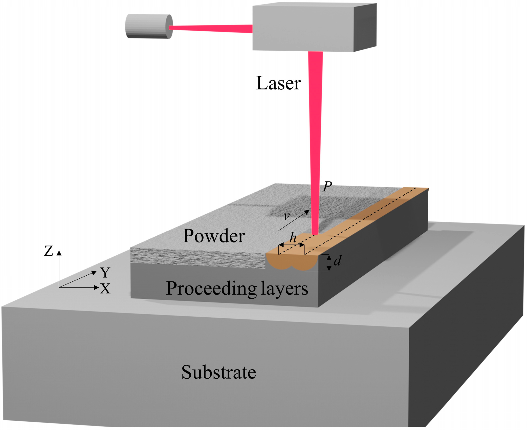
2.2. Heat Source Model

The laser energy distribution in LPBF was the Gaussian distribution, which was mathematically presented as [24]:
q ( r ) = 2 α P π ω 2 exp ( 2 r 2 ω 2 )
where q(r) is the input heat flux; α is the absorption rate of powder, which is 70%; ω is the radius of laser spot, which is 0.5 mm; P is the laser power and r is the radial distance from the center of the laser beam.

2.3. Finite Element Model

The 3D finite element model of the LPBF is shown in Figure 2a. The gray part represents the substrate, and the yellow part represents the power bed. In the simulation, the model is simplified to reduce the amount of calculation. Set the size of the substrate to 30 mm × 30 mm × 2 mm. The inner diameter of the cladding is 10 mm, the wall thickness is 1 mm. The thickness of a single powder layer was 30 μm, and three powder layers were set in the model. The mesh dimensions of cladding are 100 μm × 100 μm × 30 μm, and the mesh dimensions of the substrate are 500 μm × 500 μm × 500 μm. The three-dimensional simulation model is meshed into 38,644 nodes and 21,600 elements in total.
The scanning strategies of the laser beam are unidirectional, bidirectional and employ ring scanning, as shown in Figure 2b. Because the FeCrAl cladding has a ring structure, many scanning paths need to be defined when linear scanning is adopted. This simulation is very complicated. Therefore, parts of the ring model are used for simplification, as shown in Figure 2c. Three paths are defined to simulate the local linear scanning of the ring. According to the scanning spacing of 0.05 mm, the effective width of the three paths is 0.15 mm. The central angle of the arc length in the local model is only about 1.7 °, which is simplified as a rectangle (1 mm × 0.15 mm). The simplified substrate size is 2 mm × 1 mm × 0.25 mm. So, the three-dimensional simulation model of simplified model is meshed into 21,750 nodes and 4240 elements.
In the present model, some assumptions are made as follows [25]:
(1)
The whole FeCrAl powder bed is assumed to be a continuous and uniform medium and the heat transfer between the powder pores is not considered.
(2)
The shrinkage of the powder bed is negligible for simplifying the calculation.
(3)
The surface of the molten pool is assumed to be flat without respect to evaporation and capillary flow.
(4)
The moving laser heat source is modeled as the Gaussian distribution and is input directly on the surface of the powder layer.

2.4. Boundary Conditions

In this model, the temperature of the air and the heat transfer coefficient between the object and the air are specified. The overall initial temperature of the substrate is set to a different preheating temperature or the normal temperature (25 °C), and the bottom of the substrate is set to be insulated. The vertical contact side is static air, and its convective coefficient is set to 5 W/K m2 [26]. In the LPBF process, the powders are densely spread on the substrate to form powder layers. The flow rate of air on the powder layer and substrate surface is 0. In addition, there must be radiation heat transfer between the powder layer, the substrate and the surrounding environment, but the heat exchanged by radiation heat transfer is far less than that by convection heat transfer. As such, only convection heat transfer needs to be considered, which can be expressed as [27],
κ T z = h i ( T T E )
where hi is the thermal convection coefficient; κ is the thermal conductivity; T is temperature and TE is the environment temperature.
Table 3 lists the simulation parameters of this paper.

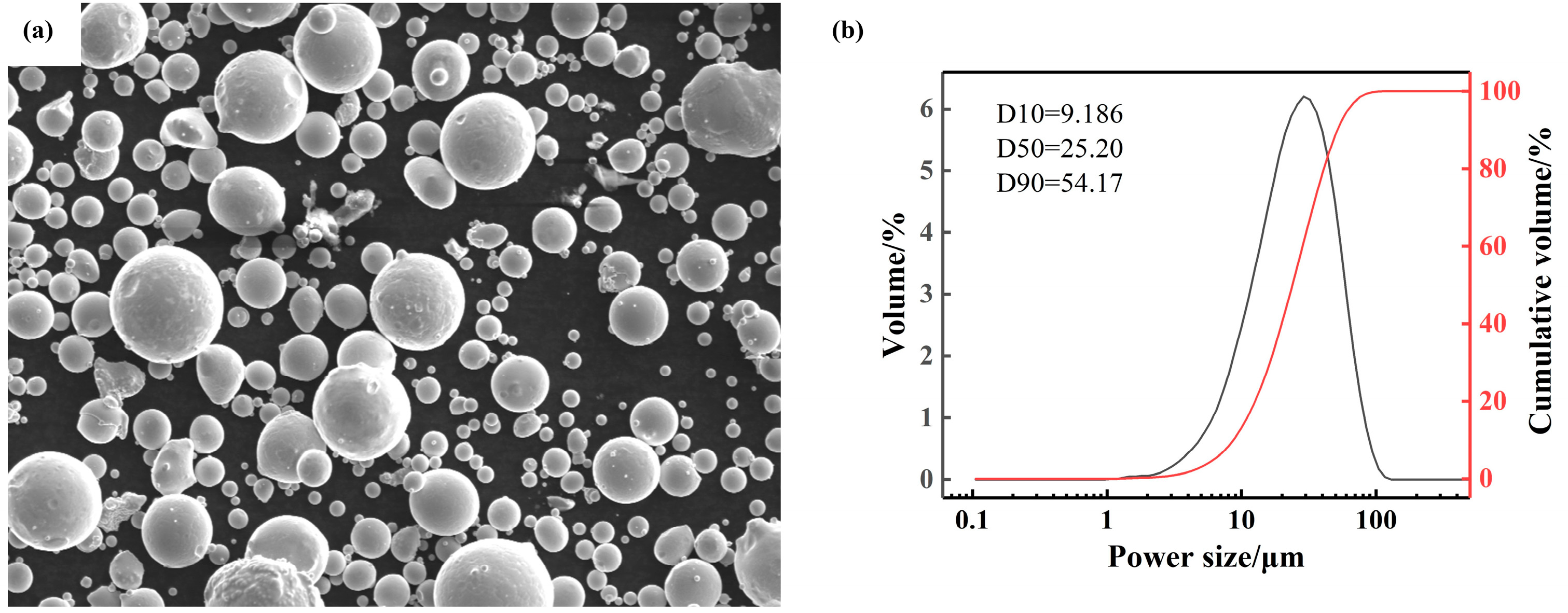
3. Materials and Experiment

Self-made gas-atomized FeCrAl alloy powders were used as raw material. Table 1 shows the chemical composition of FeCrAl alloy powder. The micromorphology of the FeCrAl alloy powders is shown in Figure 3a and the particle size distribution is shown in Figure 3b.
Laser powder bed fusion equipment (the home-built SLM-M150) was used to fabricate FeCrAl alloy specimens. The specimens were fabricated using various combinations of laser powers (200 W), scanning speeds (500 mm/s), hatching spaces (0.05 mm) and layer thickness (0.03 mm). Bidirectional scanning and ring scanning strategy were used to manufacture thin-wall cladding, respectively.
The surface roughness of cladding was measured by white light interferometry (1000 WLI). A scanning electron microscope (SU3500) was used for microstructure analysis.

4. Results and Discussion

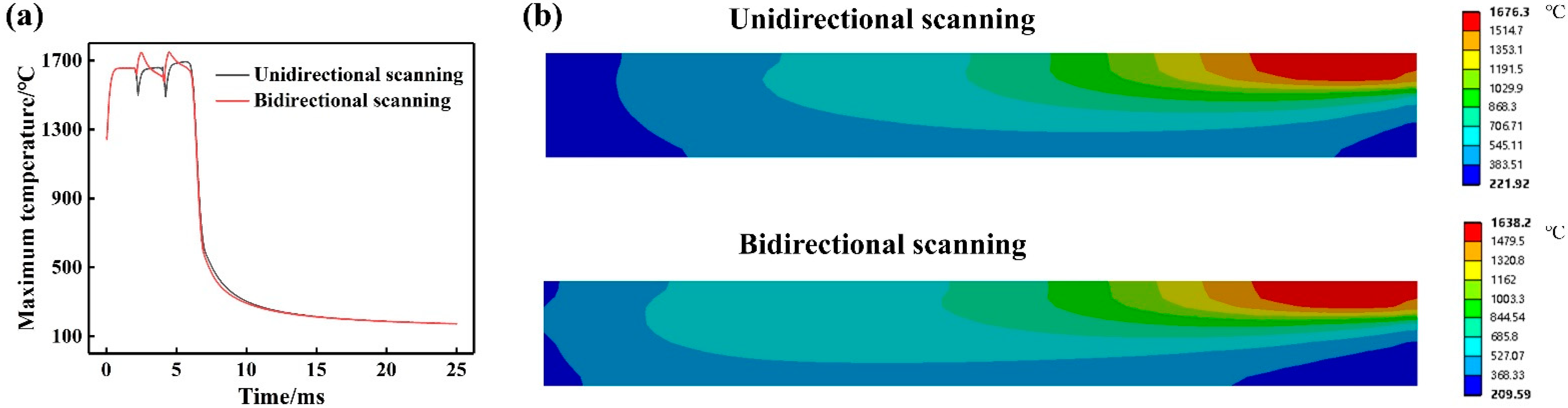
4.1. Linear Scanning Simulation

In multi-pass linear scanning, remelting zones are formed between the weld passes to achieve metallurgical bonding. Unidirectional scanning and bidirectional scanning methods are selected to conduct simulation respectively. The simulation curves of maximum temperature are shown in Figure 4a. The simple change of scanning mode has little influence on the trend of maximum temperature but has a great influence on the whole temperature field. In the process of unidirectional scanning, each laser track is not continuous. Therefore, the maximum temperature of the molten pool is stable at a constant value. About bidirectional scanning, the laser beam is continuous at the ends. Heat accumulates gradually, so the molten pool temperature continues to rise. The maximum temperature of bidirectional scanning is higher than that of unidirectional scanning. Figure 4b gives the temperature field distribution of different linear scanning at the same time. The temperature gradient along the axis of bidirectional scanning is obviously smaller than that of unidirectional scanning. The bidirectional scanning has a wide heat distribution. This is related to the thermal history of the laser scanning path. This helps to reduce axial stress and deformation of the cladding.

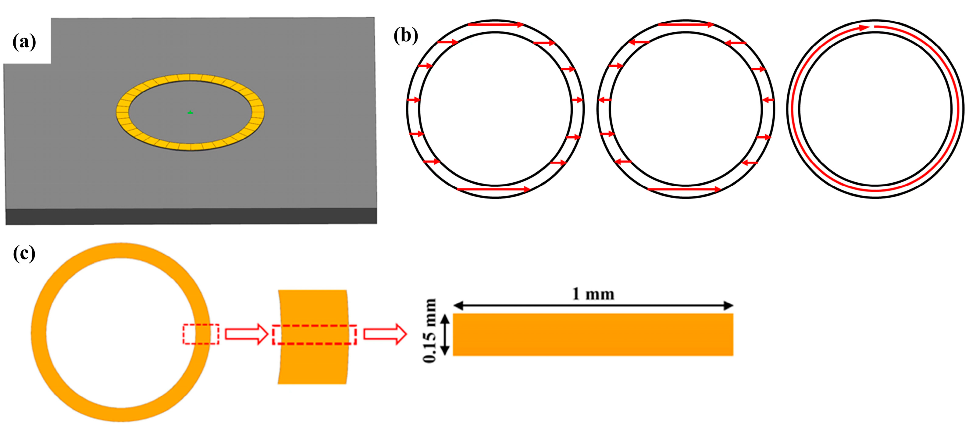
4.2. Ring Scanning Simulation

Figure 5a shows the maximum temperature variation curve of three layer at the ring scanning strategy. Figure 5b shows the temperature distribution of the first layer at six moments. After the laser scanning starts operation, the maximum temperature of the molten pool rose rapidly to above the melting point and fluctuated within a small temperature range until the scanning was completed. At the end of the first layer (t = 0.07 s), the laser spot returned near the starting point, and the residual temperature at the starting point increased the maximum temperature, as shown in Figure 5b. Then the laser heat source disappeared, and the maximum temperature decreased sharply, and gradually decreased to near the preheating temperature.
As shown in Figure 5a, because of the short interval between layers and significant heat accumulation, the maximum temperature of the third layer was significantly higher than that of the first layer. However, the temperature increases of the third layer compared with the second layer were significantly less than that of the second layer compared with the first layer. The maximum temperature tends to stabilize as the number of layers increases. This indicates that the temperature gradient decreases as the number of layers increases. The grain size is larger when the higher layer is formed. When scanning the third layer, it can be seen that the maximum temperature of the third layer is much higher than that of the second layer. There is a large temperature gradient between layers along the building direction. As the printing continues, the formed layer will still have a temperature fluctuation, so the bottom layer will go through several thermal cycles in the whole process, which will make the bottom grain also have a trend of coarsening.
Figure 6 shows the four points selected on the cladding model, and their temperature changes are shown in Figure 6b. There was almost no obvious difference between point B and point C. It can be seen that the inner and outer temperature changes of ring scanning were little affected. The maximum temperature difference between point A and D was about 530 °C, and that between point A and point C was about 120 °C.

4.3. Forming Accuracy
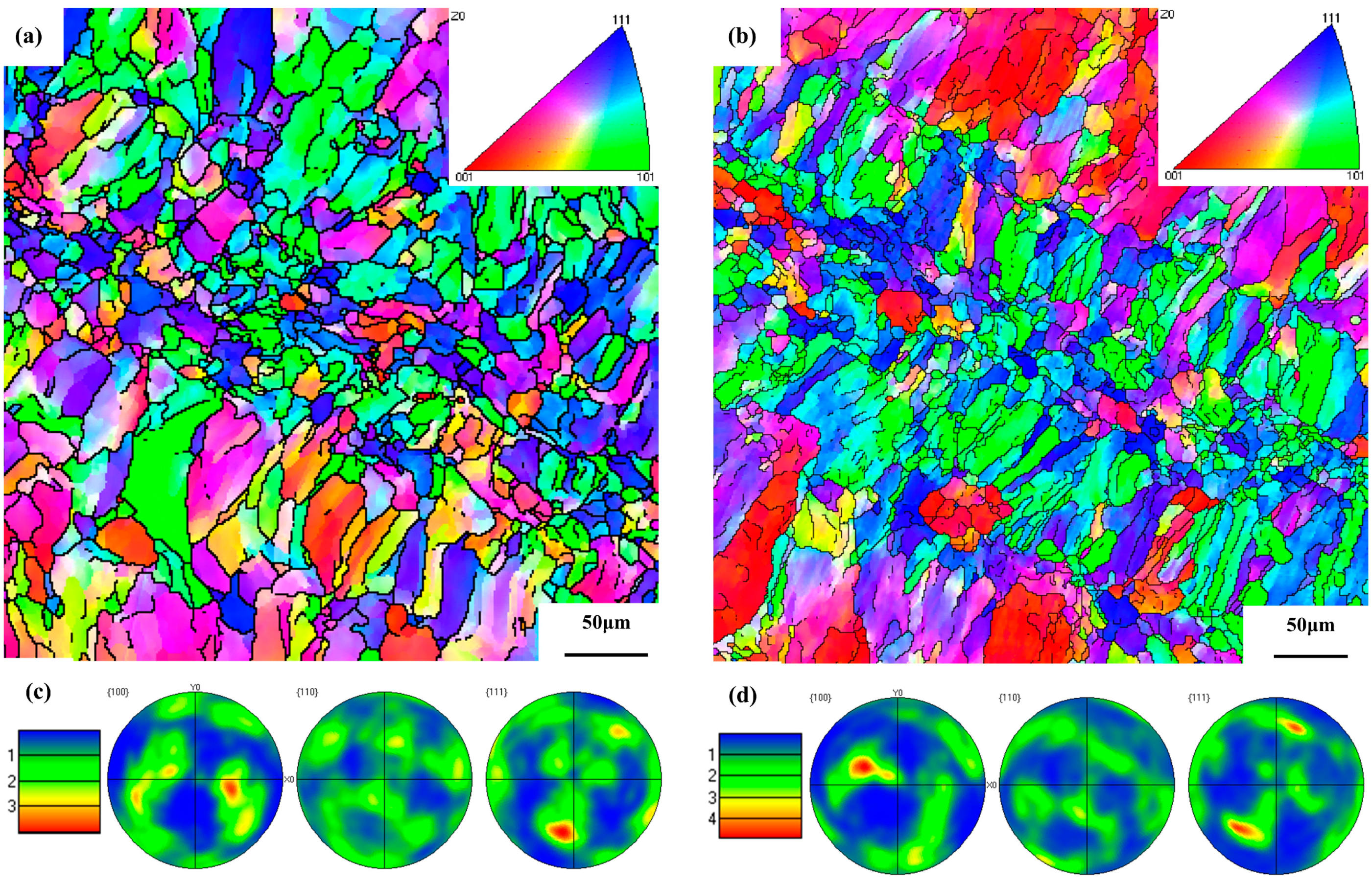
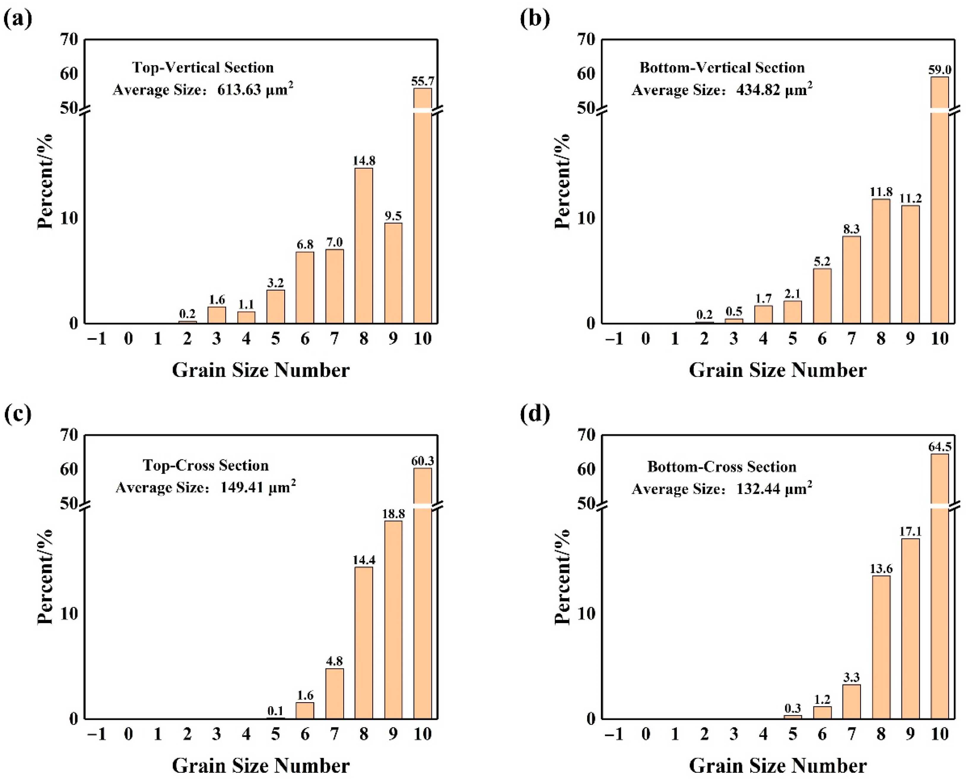
Due to the particularity of thin-wall cladding and ring shape of thin-wall cladding, ring scanning is one of the best candidates. In order to compare the advantages and disadvantages of the two scanning methods in forming FeCrAl thin-wall cladding, bidirectional and ring scanning were used respectively, as shown in Figure 7. The inner diameter of the design cladding model is 10 mm, and the wall thickness is 0.05, 0.1, 0.2, 0.4 and 0.8 mm, respectively. Figure 7a shows the actual samples used for the ring scanning and the measured wall thicknesses were 0.14, 0.18, 0.30, 0.54, and 0.96 mm, respectively. Figure 7b gives actual samples used for the bidirectional scanning and the measured wall thickness were 0.37, 0.47, 0.65 and 1.03 mm, respectively. When the wall thickness of the model is 0.05 mm, FeCrAl cladding cannot be fabricated by bidirectional scanning. It can be seen the thickness of forming cladding is greater than that of the designed model. The thinnest thickness that can be formed by bidirectional scanning is 0.37 mm and the thinnest thickness can reach 0.14 mm by ring scanning. So, the range of bidirectional scanning meeting the wall thickness requirement is small and ring scanning can fully meet the requirements of wall thickness.
White light interferometry was used to collect the outer three-dimensional shape of the FeCrAl cladding by ring scanning and bidirectional scanning respectively, as shown in Figure 8. The cladding which used ring scanning had a smaller roughness value (Ra = 4.061 μm) than the cladding using bidirectional scanning (Ra = 7.946 μm). Figure 8a illustrates that the outer part of the cladding was evenly distributed with obvious small burrs, but the outer surface was still smooth. These burrs were caused by the flow of the ring scanning pool into the gaps between the powders on both sides and can be removed by subsequent sandblasting or surface finishing. Figure 8b gives the morphology of the outer part of the cladding using bidirectional scanning. The outer surface of the cladding was uneven and had many burrs. This was because the end point and start point of each scan line of bidirectional scanning were on the outer surface, which made the surface quality of the cladding significantly worse than that of the ring scanning. Therefore, in order to control the wall thickness within 0.4 mm and obtain better surface quality, the ring scanning was obviously better than the bidirectional scanning.

4.4. Microstructure

FeCrAl cladding of 50 mm high and 1 mm wall thickness manufactured using a ring-type scanning strategy was selected. The top (45–50 mm) and bottom (0–5 mm) of the cladding were cut, respectively. The vertical and cross-sections at the top and bottom of the sample were characterized by EBSD characterization.
The microstructure of the top and bottom vertical sections of the FeCrAl cladding is shown in Figure 9. The grains at the bottom were more concentrated in <001> and <101> direction, while in <111> direction grains were fewer. The grain orientation at the top was distributed in <001>, <101> and <111> directions without obvious optimization of grain direction. Meanwhile, Figure 9c,d give the pole figure of the top and bottom vertical sections of the cladding, respectively. There was no strong texture in either. Figure 10 illustrates the microstructure of the top and bottom cross-sections of the FeCrAl cladding. There was no obvious optimization of grain orientation in the two sections. The orientation of grain was distributed in <001>, <101> and <111> directions. Figure 10c,d are polar diagrams of cross-sections at the top and bottom of the cladding, respectively. The two cross-sections also show no strong texture. Figure 10b shows that the orientation of grains in the middle region were very different from those on both sides. The grains in the middle region were concentrated in <100> and <111> directions, and the grains on both sides were concentrated in <001> direction. The heat dissipation conditions of different parts of the ring were different and the orientation of different parts of the grain was different, and so the optimization of the orientation of the whole grain was not obvious. However, the metal powders around the cladding forming had preheating and heat transfer qualities. The temperature was obviously higher than the top of the air; the vertical direction was still the main direction of heat dissipation. The temperature gradient in the building direction was still significantly greater than that in the horizontal direction, and the grains were still columnar.
Figure 11 shows the grain size distribution of the vertical and cross sections at the top and bottom of the cladding. The average grain size at the bottom of the vertical section was 434.82 μm2, and the average grain size at the top was 613.63 μm2. The average grain size at the bottom of the cross section was 132.44 μm2, and the average grain size at the top was 149.41 μm2. The grains at the top were significantly larger than those at the bottom. With the increase in the number of processing layers, the temperature gradient at the beginning of the condensation of the top molten pool was much smaller than that at the beginning of the condensation of the bottom molten pool when the heat accumulation tends to be stable.

5. Conclusions

In this study, thin-wall FeCrAl claddings are fabricated by laser powder bed fusion. The effect of the scanning strategy was studied by simulation and experiment. The main conclusions are as follows:
(1)
Linear scanning simulation shows that the maximum temperature of unidirectional scanning is stable. The maximum temperature of bidirectional scanning is higher than that of unidirectional scanning. The bidirectional scanning has a smaller temperature gradient along the radial direction. It can help to improve the dimensional accuracy of the FeCrAl cladding.
(2)
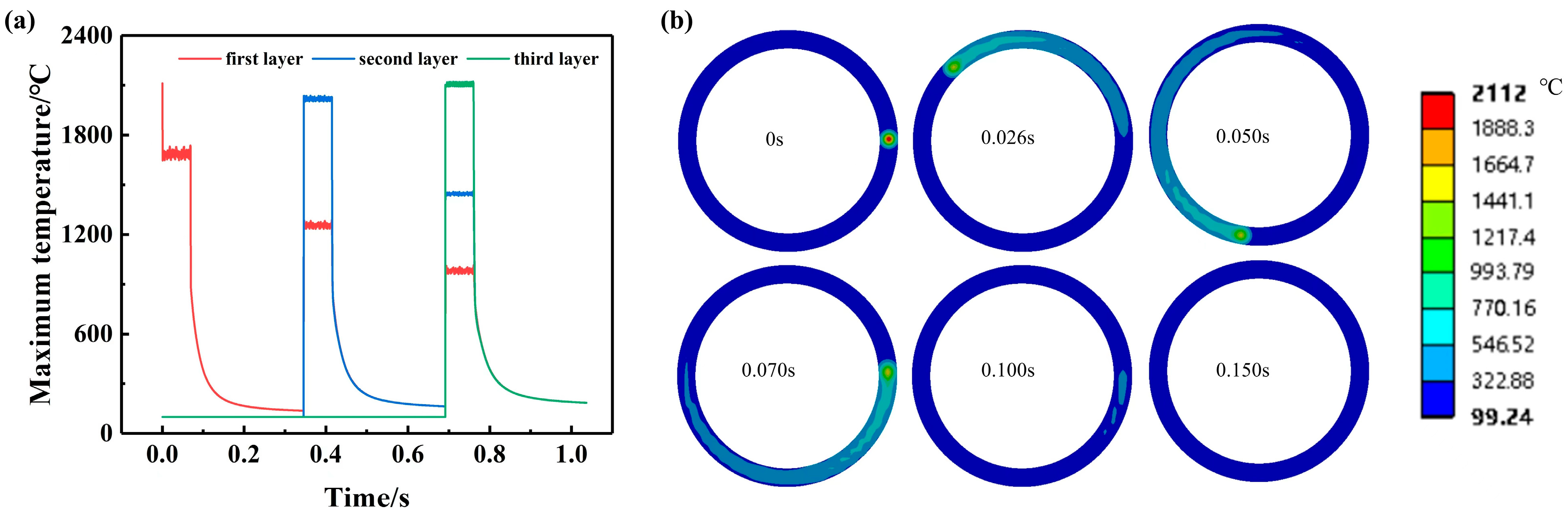
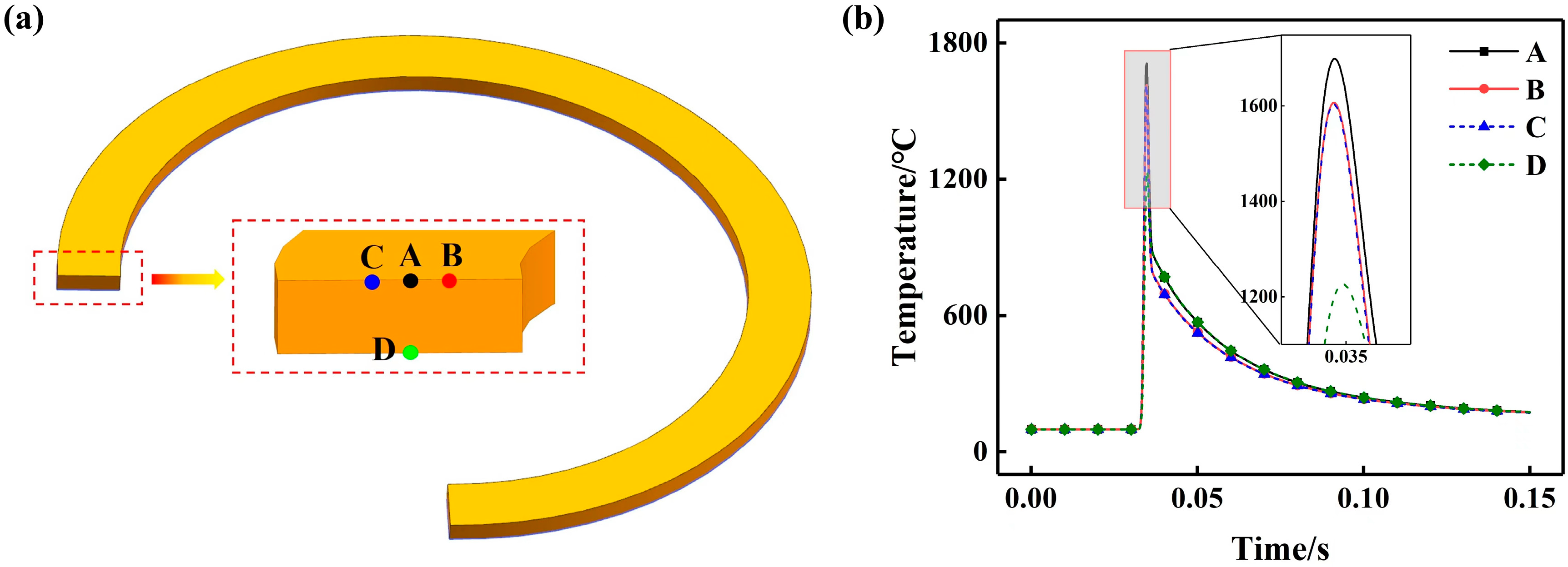
Ring scanning simulation gives the maximum temperature fluctuated within a very small temperature range after the laser scanning began. The maximum temperature gradually increases and then tends to be stable with the increase of layers. The temperature gradient is greatest along the building direction.
(3)
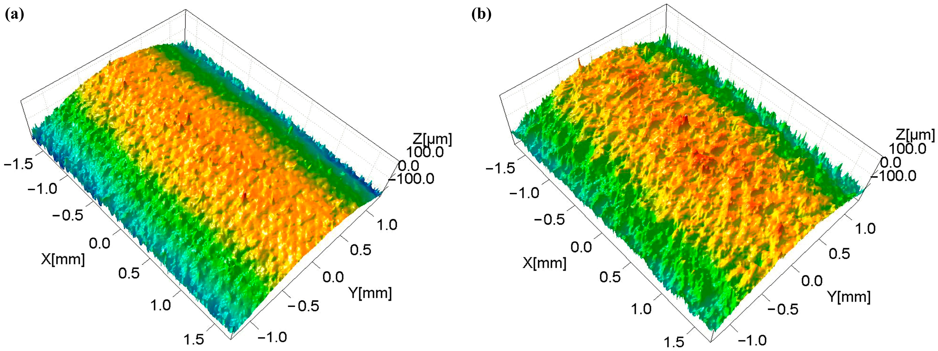
Thin-wall cladding samples were fabricated by LPBF. The thinnest shell thickness is 0.37 mm in the bidirectional scanning strategy, and 0.14 mm in ring scanning strategy. The cladding used for the ring scanning has a smaller roughness value (Ra = 4.061 μm) than the cladding used for bidirectional scanning (Ra = 7.946 μm). When the thickness of thin-walled cladding is less than 0.4 mm, the manufacturing accuracy of ring scanning is better than that of bidirectional scanning.
(4)
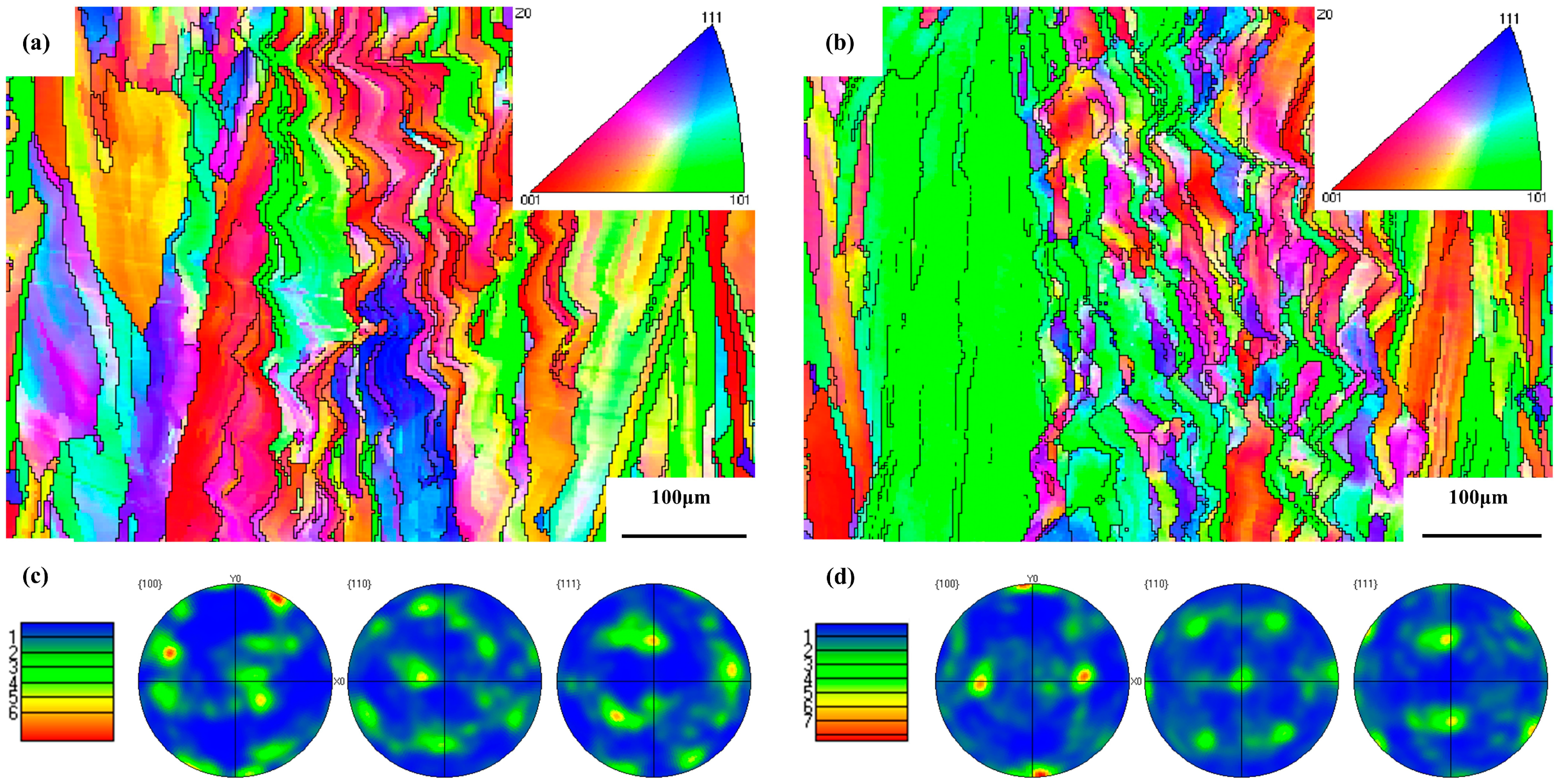
The grain size of the top and bottom of the cladding was analyzed. The grain of the cladding is columnar. The grain size at the top is larger than that at the bottom due to thermal accumulation.

Author Contributions

Conceptualization, F.C. and H.Z. (Haitian Zhang); methodology, F.C. and H.Z. (Haitian Zhang); software, H.Z. (Haitian Zhang) and H.Z. (Hang Zhou); validation, F.C. and H.Z. (Hang Zhou); formal analysis, Y.H. and S.L.; investigation, F.C., Y.R. and J.Z.; resources, F.C., K.M. and Z.L.; data curation, Y.H.; writing—original draft preparation, F.C., H.Z. (Haitian Zhang) and H.Z. (Hang Zhou); writing—review and editing, H.Z. (Hang Zhou), K.M. and Z.L.; visualization, F.C.; supervision, D.L.; project administration, Z.L.; funding acquisition, Z.L. All authors have read and agreed to the published version of the manuscript.

Funding

This work was funded by the Key project of Nuclear Safety and advanced Nuclear Technology, grant number 2019YFB1901002.

Institutional Review Board Statement

Not applicable.

Informed Consent Statement

Not applicable.

Data Availability Statement

Not applicable.

Conflicts of Interest

The authors declare no conflict of interest.

References

  1. Chen, P.; Qiu, B.; Wu, J.; Zheng, M.; Gao, S.; Zhang, K.; Zhou, Y.; Wu, Y. A comparative study of in-pile behaviors of FeCrAl cladding under normal and accident conditions with updated FROBA-ATF code. Nucl. Eng. Des. 2021, 371, 110889. [Google Scholar] [CrossRef]
  2. Tang, C.; Jianu, A.; Steinbrueck, M.; Grosse, M.; Weisenburger, A.; Seifert, H.J. Influence of composition and heating schedules on compatibility of FeCrAl alloys with high-temperature steam. J. Nucl. Mater. 2018, 511, 496–507. [Google Scholar] [CrossRef]
  3. Duan, Z.; Yang, H.; Satoh, Y.; Murakami, K.; Kano, S.; Zhao, Z.; Shen, J.; Abe, H. Current status of materials development of nuclear fuel cladding tubes for light water reactors. Nucl. Eng. Des. 2017, 316, 131–150. [Google Scholar] [CrossRef]
  4. Park, D.J.; Kim, H.G.; Jung, Y.I.; Park, J.H.; Yang, J.H.; Koo, Y.H. Microstructure and mechanical behavior of Zr substrates coated with FeCrAl and Mo by cold-spraying. J. Nucl. Mater. 2018, 504, 261–266. [Google Scholar] [CrossRef]
  5. Chang, K.; Meng, F.; Ge, F.; Zhao, G.; Du, S.; Huang, F. Theory-guided bottom-up design of the FeCrAl alloys as accident tolerant fuel cladding materials. J. Nucl. Mater. 2019, 516, 63–72. [Google Scholar] [CrossRef]
  6. Field, K.G.; Yamamoto, Y.; Pint, B.A.; Gussev, M.N.; Terrani, K.A. Accident tolerant FeCrAl fuel cladding: Current status towards commercialization. In Proceedings of the 18th International Conference on Environmental Degradation of Materials in Nuclear Power Systems–Water Reactors, Portland, OR, USA, 13–17 August 2019; pp. 1381–1389. [Google Scholar]
  7. Park, D.J.; Kim, H.G.; Park, J.Y.; Jung, Y.I.; Park, J.H.; Koo, Y.H. A study of the oxidation of FeCrAl alloy in pressurized water and high-temperature steam environment. Corros. Sci. 2015, 94, 459–465. [Google Scholar] [CrossRef]
  8. Gupta, V.K.; Larsen, M.; Rebak, R.B. Utilizing FeCrAl oxidation resistance properties in water, air and steam for accident tolerant fuel cladding. ECS Trans. 2018, 85, 3. [Google Scholar] [CrossRef]
  9. Alrwashdeh, M.; Alameri, S.A. Preliminary neutronic analysis of alternative cladding materials for APR-1400 fuel assembly. Nucl. Eng. Des. 2021, 384, 111486. [Google Scholar] [CrossRef]
  10. Bartkowiak, K.; Ullrich, S.; Frick, T.; Schmidt, M. New developments of laser processing aluminium alloys via additive manufacturing technique. Phys. Procedia 2011, 12, 393–401. [Google Scholar] [CrossRef]
  11. Amato, K.; Gaytan, S.; Murr, L.E.; Martinez, E.; Shindo, P.; Hernandez, J.; Collins, S.; Medina, F. Microstructures and mechanical behavior of Inconel 718 fabricated by selective laser melting. Acta Mater. 2012, 60, 2229–2239. [Google Scholar] [CrossRef]
  12. Thijs, L.; Kempen, K.; Kruth, J.-P.; Van Humbeeck, J. Fine-structured aluminium products with controllable texture by selective laser melting of pre-alloyed AlSi10Mg powder. Acta Mater. 2013, 61, 1809–1819. [Google Scholar] [CrossRef]
  13. Nagahari, T.; Nagoya, T.; Kakehi, K.; Sato, N.; Nakano, S. Microstructure and creep properties of Ni-Base Superalloy IN718 built up by selective laser melting in a vacuum environment. Metals 2020, 10, 362. [Google Scholar] [CrossRef]
  14. Xiao, Z.; Yang, Y.; Wang, D.; Song, C.; Bai, Y. Structural optimization design for antenna bracket manufactured by selective laser melting. Rapid Prototyp. J. 2018, 24, 539–547. [Google Scholar] [CrossRef]
  15. Mohanty, S.; Hattel, J. Cellular scanning strategy for selective laser melting: Capturing thermal trends with a low-fidelity, pseudo-analytical model. Math. Probl. Eng. 2014, 2014, 715058. [Google Scholar] [CrossRef]
  16. He, K.; Zhao, X. 3D thermal finite element analysis of the SLM 316L parts with microstructural correlations. Complexity 2018, 2018, 6910187. [Google Scholar] [CrossRef]
  17. Roberts, I.A.; Wang, C.; Esterlein, R.; Stanford, M.; Mynors, D. A three-dimensional finite element analysis of the temperature field during laser melting of metal powders in additive layer manufacturing. Int. J. Mach. Tools Manuf. 2009, 49, 916–923. [Google Scholar] [CrossRef]
  18. Hussein, A.; Hao, L.; Yan, C.; Everson, R. Finite element simulation of the temperature and stress fields in single layers built without-support in selective laser melting. Mater. Des. 2013, 52, 638–647. [Google Scholar] [CrossRef]
  19. Parry, L.; Ashcroft, I.; Wildman, R.D. Understanding the effect of laser scan strategy on residual stress in selective laser melting through thermo-mechanical simulation. Addit. Manuf. 2016, 12, 1–15. [Google Scholar] [CrossRef]
  20. Walker, J.C.; Berggreen, K.M.; Jones, A.R.; Sutcliffe, C.J. Fabrication of Fe–Cr–Al oxide dispersion strengthened PM2000 alloy using selective laser melting. Adv. Eng. Mater. 2009, 11, 541–546. [Google Scholar] [CrossRef]
  21. Boegelein, T.; Louvis, E.; Dawson, K.; Tatlock, G.J.; Jones, A.R. Characterisation of a complex thin walled structure fabricated by selective laser melting using a ferritic oxide dispersion strengthened steel. Mater. Charact. 2016, 112, 30–40. [Google Scholar] [CrossRef] [Green Version]
  22. Yamamoto, Y.; Pint, B.A.; Terrani, K.A.; Field, K.G.; Yang, Y.; Snead, L.L. Development and property evaluation of nuclear grade wrought FeCrAl fuel cladding for light water reactors. J. Nucl. Mater. 2015, 467, 703–716. [Google Scholar] [CrossRef]
  23. Field, K.G.; Snead, M.A.; Yamamoto, Y.; Terrani, K.A. Handbook on the Material Properties of FeCrAl Alloys for Nuclear Power Production Applications; Nuclear Technology Research and Development; Oak Ridge National Laboratory: Oak Ridge, TN, USA, 2017. [Google Scholar]
  24. Yin, J.; Zhu, H.; Ke, L.; Lei, W.; Dai, C.; Zuo, D. Simulation of temperature distribution in single metallic powder layer for laser micro-sintering. Comput. Mater. Sci. 2012, 53, 333–339. [Google Scholar] [CrossRef]
  25. Huang, W.; Zhang, Y. Finite element simulation of thermal behavior in single-track multiple-layers thin wall without-support during selective laser melting. J. Manuf. Processes 2019, 42, 139–148. [Google Scholar] [CrossRef]
  26. Kosky, P.; Balmer, R.T.; Keat, W.D.; Wise, G. Exploring Engineering: An Introduction to Engineering and Design, 5th ed.; Academic Press: Cambridge, MA, USA, 2021; pp. 317–340. [Google Scholar]
  27. Duan, W.; Yin, Y.; Zhou, J. Temperature field simulations during selective laser melting process based on fully threaded tree. Chin. Foundry 2017, 14, 405–411. [Google Scholar] [CrossRef] [Green Version]
Figure 1. LPBF process.
Crystals 12 01197 g001
Figure 2. (a) 3D finite element model; (b) unidirectional, bidirectional and ring scanning strategies; (c) parts of the ring model.
Crystals 12 01197 g002
Figure 3. (a) The micromorphology of FeCrAl alloy powders and (b) the particle size distribution.
Crystals 12 01197 g003
Figure 4. (a) The simulation curves of maximum temperature under different linear scanning; (b) temperature field distribution of different linear scanning at the same time.
Crystals 12 01197 g004
Figure 5. (a) Maximum temperature curve of ring scanning, (b) temperature field distribution of the first layer of the ring scanning.
Crystals 12 01197 g005
Figure 6. The temperature changes with time at different points on the longitudinal section: (a) the distance from point A to point B is 0.1 mm, the distance from point A to point C is 0.1 mm, the distance from point A to point D is 0.03 mm, and (b) temperature curve over time.
Crystals 12 01197 g006
Figure 7. FeCrAl cladding of different thickness in LPBF, (a) ring scanning and (b) bidirectional scanning.
Crystals 12 01197 g007
Figure 8. The outer three-dimensional shape of FeCrAl cladding in LPBF, (a) ring scanning and (b) bidirectional scanning.
Crystals 12 01197 g008
Figure 9. EBSD analysis of vertical sections of top (a,c) and bottom (b,d) of thin-wall cladding, (c,d) pole figure of (a,b).
Crystals 12 01197 g009
Figure 10. EBSD analysis of cross-sections of top (a,c) and bottom (b,d) of thin-wall cladding, (c,d) pole figure of (a,b).
Crystals 12 01197 g010
Figure 11. Grain size distribution of vertical sections (a,b) and cross-sections (c,d) of FeCrAl cladding at the top region (a,c) and the bottom region (b,d).
Crystals 12 01197 g011
Table 1. Chemical composition of FeCrAl alloy and C35M (in wt.%).
IDsFeMoAlCrCONS
FeCrAl81.271.983.9212.82<0.018<0.008<0.074<0.003
C35M80.1524.513----
Table 2. Thermal physical of FeCrAl.
Temperature (K)27040060080010001200140016001800
Thermal conductivity (W/m K)12.514.317.019.521.924.026.128.029.7
Specific heat (J/kg K)423.3513.8616.8791.4742.9709.4741.3855.91082.5
Density (kg/m3)7.107.067.016.946.846.726.596.436.26
Table 3. Simulation parameters.
Parameter UnitValue
Laser powerW200
Scan speedmm/s500
Hatching spacesmm0.05
Layer thicknessmm0.03
Initial temperature°C25
Thermal conductivityW/m KTable 2
Specific heatJ/kg KTable 2
Densitykg/m3Table 2
Absorption%70
Radius of laser spotmm0.5
Convective heat transfer coefficientW/K m25
Publisher’s Note: MDPI stays neutral with regard to jurisdictional claims in published maps and institutional affiliations.

