Article

Fabrication and Characterization of Lead-Free BNT-6BT Ultrasonic Transducers Designed by an Intelligent Optimization Algorithm

1
Electronic Materials Research Laboratory, Key Laboratory of the Ministry of Education & International Center for Dielectric Research, School of Electronic Science and Engineering, Xi’an Jiaotong University, Xi’an 710049, China
2
School of Equipment Management, Engineering University of PAP, Xi’an 710089, China
3
School of Microelectronics, Xidian University, Xi’an 710071, China
4
Guangdong JC Technological Innovation Electronics Co., Ltd., Zhaoqing 526000, China
*
Authors to whom correspondence should be addressed.
These authors contributed equally to this work.
Crystals 2022, 12(8), 1181; https://doi.org/10.3390/cryst12081181
Submission received: 29 July 2022 / Revised: 14 August 2022 / Accepted: 17 August 2022 / Published: 22 August 2022
(This article belongs to the Special Issue Lead-free Ferro-/Piezoelectric Ceramics and Thin Films)

Abstract

:
Lead-free piezoelectric material-based ultrasonic transducers have been researched for several years, but the inefficient properties and design difficulties have troubled lead-free ultrasonic transducers for a long time. To improve the performance and design efficiency of lead-free ultrasonic transducers, in this work, an equivalent circuit model and intelligent optimization algorithm were combined for use in a transducer design. Firstly, 0.94(Bi0.5Na0.5)TiO3-0.06BaTiO3(BNT-6BT) lead-free piezoelectric ceramics were prepared and characterized. Then, BNT-6BT ceramics were used to fabricate the ultrasonic transducers. An equivalent circuit model-based software, PiezoCAD, and a genetic algorithm-based back-propagation neural network were used to optimize the design of the transducers. A 3.03 MHz center frequency and 60.3% −6 dB bandwidth of the optimized transducers were achieved, which were consistent with the neural networks optimization results. To verify the application potential of the lead-free transducers, tungsten rods phantom imaging and polystyrene spheres with 300 μm diameter manipulation were completed by the transducers, and the experiment results indicate that the BNT-6BT lead-free transducers have great potential in further biological and biomedical applications.

Graphical Abstract

1. Introduction

Piezoelectric materials are the kinds of materials that can convert signals between mechanical and electric energy, which are used in transducers, sensors, actuators, motors, and buzzers [1,2,3]. In past years, the most widely used piezoelectric materials were Pb(Zrx, Ti1−x)O3 (PZT)-based ceramics [4,5]. However, the lead (Pb) in PZT-based ceramics is one of the most important reasons for environment pollution [6,7]. Thus, lead-free piezoelectric materials are urgently needed for industry, which is facing a shortage of lead-based materials. Among all the novel lead-free piezoelectric materials, (Bi0.5Na0.5)TiO3 (BNT)-based ceramics are one of the most promising candidates to replace PZT-based ceramics. In our previous work, we found out that there is a morphotropic phase boundary (MPB) between the rhombohedral phase and tetragonal phase in BNT-xBaTiO3 components with x = 0.06 (BNT-6BT) [8,9]. Several studies have illustrated that the piezoelectric solid solution component would show excellent piezoelectric and ferroelectric properties near the MPB. Therefore, BNT-6BT lead-free ceramics could be used in further applications [10,11].
Ultrasonic transducers are widely used in medical diagnosis fields because of their non-invasiveness, high resolution, and large detecting depth [12,13,14,15]. The key part of ultrasonic transducers is the piezoelectric materials. It has been proven that novel lead-free piezoelectric materials could be used in ultrasonic transducer applications. In addition, the performance of the transducer is mainly affected by its design parameters. The size and thickness of piezoelectric materials could determine the center frequency and electrical impedance. The acoustic impedance and thickness of piezoelectric materials and matching layers could affect the acoustic transmission between transducers and the front medium. As a multifactor affected goal, it is unavoidable to adjust the design parameters many times to obtain the desired performance parameters [16,17,18]. For the traditional design method, the trial-and-error method mainly relies on the designer’s experience. Therefore, a high-efficiency design method for transducers is urgently needed.
In recent years, artificial intelligence methods, such as neural networks, intelligent optimization algorithms, expert systems, etc., have been widely used in industry, medicine, education, and information [15,16,19]. Neural networks have the advantages of efficient modeling and data mining. Neural networks intelligent optimization is widely used in the modeling of complex systems because of its self-adaptation, self-organization, self-learning, and robustness [20,21]. Therefore, it can be used for the optimal design and manufacture of high-performance transducers. For the ultrasonic transducers, a Krimholtz–Leedom–Mattaei (KLM) equivalent circuit model is one of the most important methods used to determine the relationship between design and performance [22,23]. Combining the KLM model and neural networks could highly improve the efficiency and accuracy of the design and manufacture of ultrasonic transducers.
In this paper, BNT-6BT ceramics were prepared and investigated. An efficient optimization design method based on KLM model-based PiezoCAD software (Sonic Concepts, Inc., Bothell, USA) a genetic algorithm-based back-propagation neural network (GA-BPNN), and a particle swarm optimization (PSO) algorithm was used to design BNT-6BT based lead-free ultrasonic transducers. The database of design parameters and performance parameters is provided by PiezoCAD software. According to the optimized parameters, BNT-6BT based ultrasonic transducers were prepared and measured. When a focal lens was added into the transducers, the acoustic imaging and acoustic tweezers applications were achieved.

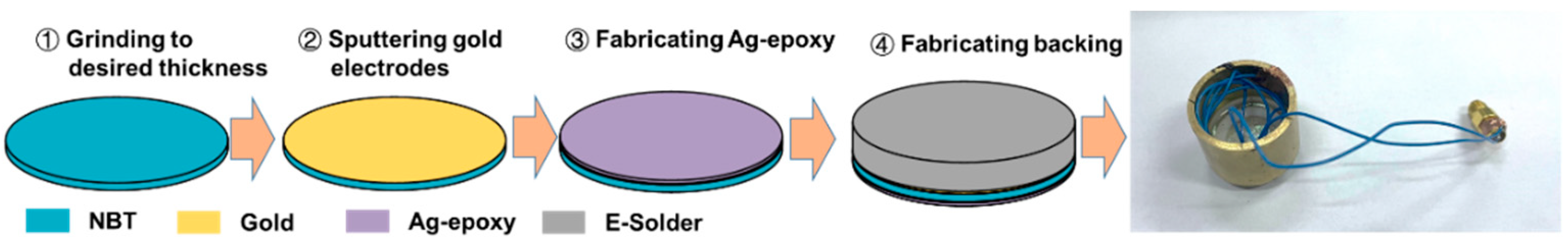
2. Materials and Methods

2.1. BNT-6BT Ceramics

BNT-6BT ceramics were prepared by Bi2O3, TiO2, Na2CO3, and BaCO3 as raw materials with the stoichiometric formulas. The powders were mixed and were then ball milled for 15 h with ethanol. The mixtures were dried under 90 °C for 4 h, pressed into pellets, and calcined at 900 °C for 2 h. After calcination, the powder was ball milled for 15 h and dried under 90 °C for 4 h. Then the BNT-6BT powder was added to PVA binder and pressed into pellets of 10 mm diameter under 200 MPa. Finally, the green sheets were sintered through two steps: at 600 °C for 4 h and 1150 °C for 2 h.
The phases of BNT-6BT ceramics were measured by X-ray diffractometer (D/MAX-2400, Rigaku, Japan, Cu Kα radiation). The surface morphology images of the ceramics were obtained using field-emission scanning electron microscopy (SEM) equipment (FEI Quanta, 250 FEG, Hillsboro, USA). The temperature dependences, dielectric constant, and dielectric loss were measured by an LCR meter (4980A, Agilent Technologies Inc., Santa Clara, USA). The piezoelectric strain, and P-E and S-E hysteresis loops were measured by using a ferroelectric testing system (TF Analyzer 2000E, aixACCT, Aachen, Germany).
In Figure 1a, the XRD pattern of BNT-6BT ceramics shows a pure perovskite structure with no secondary phase, and the surface morphology of BNT-6BT ceramics can be obtained in Figure 1b. The grain sizes are about 2 μm, and there is almost no pore on the surface. At the same time, the relative density is 96.5%, which illustrates that the ceramics are of good quality.
The BNT-6BT ceramics were poled under an external electric field of two times the coercive electric field Ec for 15 min in silicon oil at room temperature. Then the piezoelectric coefficient d33 was measured by a quasi-static d33 m after poling. The d33 value of the BNT-6BT ceramics is about 130 pC/N, indicating that the ferroelectric dipoles were aligned along the direction of the external electric field.
The temperature dependance, dielectric constant, and loss are shown in Figure 2a, in which two dielectric anomalies were observed in the BNT-6BT ceramics. At room temperature, the dielectric constant and loss of BNT-6BT ceramics are 1784 and 0.051, respectively. Between 250 °C and 300 °C, there is a broadened peak with the maximum dielectric constant, which is defined as Tm. As the temperature increases, there are sudden changes for both remnant polarization (Pr) and maximum strain (Smax), as shown in Figure 2b–d.
The temperature-dependent polarization was measured and is illustrated in Figure 2b. The Pr is 34.3 μC/cm2 at room temperature. With an increase in temperature, the Pr value decreased. Pr was 30.6 μC/cm2 at 90 °C, and the value was close to 0 when the temperature was higher than 110 °C. The bipolar strain (S-E) hysteresis loops and piezoelectric strain show the same trend, which can be found in Figure 2c,d, respectively. The Smax for the piezoelectric strain was about 1.41 ‰ under 60 kV/cm at room temperature, suggesting that the d33* was about 237 pm/V. The Smax increased with the increase in temperature. When the temperature was 90 °C, the Smax was about 1.95 ‰ with d33* = 326 pm/V. Then the Smax suddenly increased to 1.41 ‰ with d33* = 699 pm/V when the temperature reached 110 °C. Finally, the Smax decreased with the increase in temperature when the temperature was higher than 110 °C.

2.2. Optimization of Transducer Design

The design parameters of ultrasonic transducer include piezoelectric layer thickness, piezoelectric layer diameter, and matching layer thickness. The performance parameters of the ultrasonic transducer include center frequency and −6 dB bandwidth. The design parameters of the transducer are shown in Table 1. Based on the traditional design rules: the thickness of the piezoelectric layer is one-half of the wavelength; the thickness of the matching layer is one-quarter of the wavelength. Due to the complex influence of the design parameters, the traditional design method cannot effectively determine the optimal design parameters. To further optimize the thickness and diameter of the BNT-6BT ceramics, and the thickness of Ag-epoxy matching layer, their ranges were arranged from 745 μm to 785 μm, 11 mm to 19 mm, and 155 μm to 195 μm, respectively. In order to reduce the number of calculation times and ensure the accuracy of results, an orthogonal design was used. The specific content of the orthogonal design is shown in the Table S1, including the performance parameters corresponding to the design parameters.
The relationship between design parameters and performance parameters was established by training a GA-BPNN model. Then, the PSO algorithm was adopted to optimize the design parameters according to the established optimization criteria. The details of the neural network can be found in our previous work [21]. The flowchart of training GA-BPNN is shown in Figure 3.
In this work, the optimized performance parameters of the transducer are the center frequency and −6 dB bandwidth. The objective function is J, which is the sum of the normalized performance parameters with the weight coefficient. The objective function can be expressed as
J = α ( C F C F d e s C F max C F min ) + β ( B W B W d e s B W max B W min )
where α and β are the weights of center frequency and −6 dB bandwidth, respectively. In this study, the weights a and b are both 0.5, CFdes and BWdes are 3 MHz and 60%, respectively.
To reduce the errors generated in the optimization calculation process, 30 independent calculations were adopted. In addition, the purpose of setting the number of iterations in each independent calculations to 50 is to ensure the accuracy and efficiency of the calculation. Figure 4 shows the best fitness of the optimization method. The optimal fitness value is close to 0 after 50 iterations, which proves the excellent quality of the optimization algorithm.
Based on the trained GA-BPNN, the improved particle swarm algorithm is used for 30 calculations, and the performance parameters shown in Figure 5 are obtained. The thickness of the piezoelectric sheet is 765 μm with a diameter of 14.85 mm, and the thickness of Ag-Epoxy is 165 μm. In addition, the results obtained by 30 calculations present no difference, which proves the stability and effectiveness of the optimization method. As shown in Figure 6, the center frequency is 3 MHz and the bandwidth is 60%, which satisfies the desired requirement. Table 2 shows the mean value and standard deviation of the optimization results. Compared to the mean value, the standard deviation of the 30 simulation results is extremely small, which also proves the effectiveness of the optimization method.

3. Results

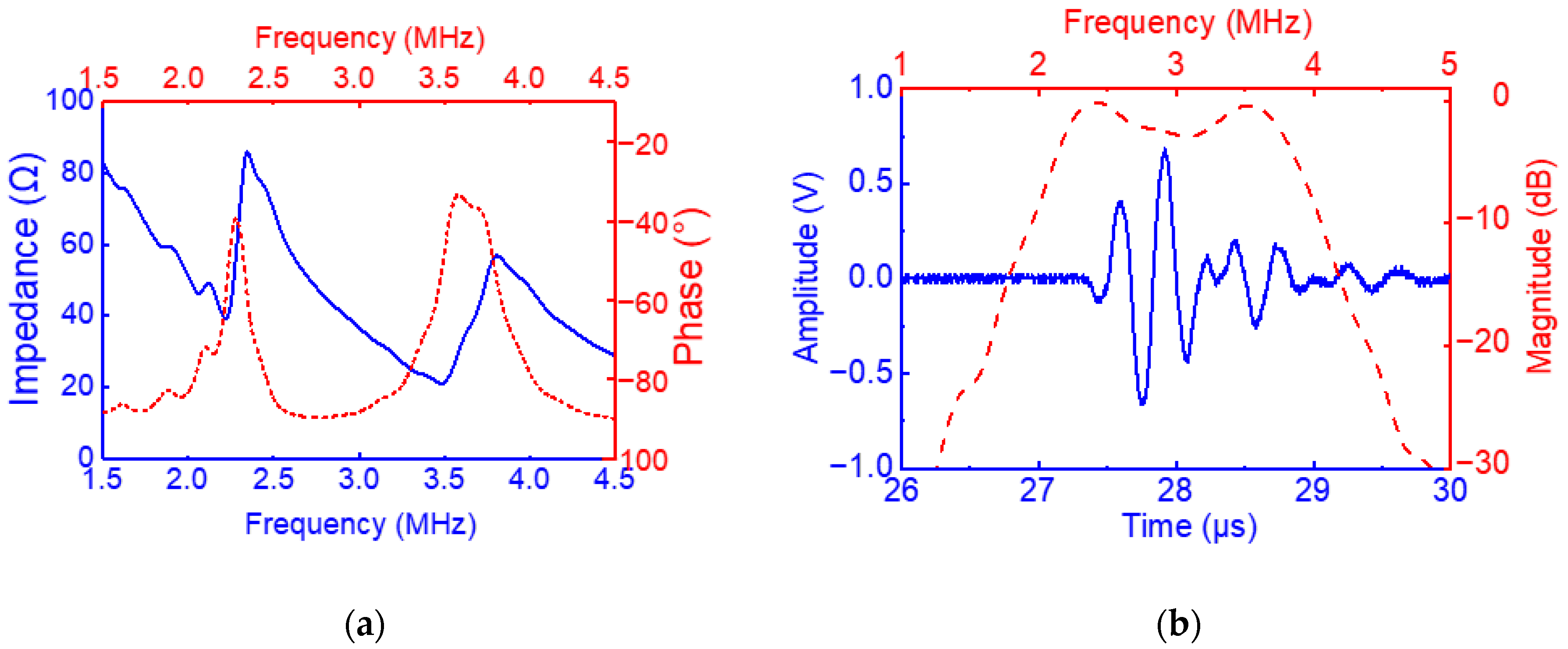
3.1. Simulation and Experimental Results of Transducers

Based on the optimized design parameters from Figure 5, PiezoCAD software was used to evaluate the optimized transducer. The backing material is E-solder (acoustic impedance 5.92 MRayl), and the propagation medium is water (acoustic impedance 1.54 MRayl). The pulse-echo diagram and impedance phase diagram obtained from the simulation are shown in Figure 7. The center frequency is 3 MHz, and the −6 dB bandwidth is 60.5%, which is consistent with the performance parameters obtained by optimization.
To further evaluate the effectiveness of the optimization method, ultrasonic transducers were fabricated based on the optimization results. First, the BNT-6BT ceramics were polished to 765 μm. Then, the gold electrodes were sputtered, and the configured Ag-epoxy was filled on the surface of the samples at room temperature for 24 h. Significantly, Ag-epoxy was made by mixing silver powder and epoxy resin in a certain proportion (3:1.25). Before mixing, the prepared epoxy solution was evacuated for 30 min to remove air from the solution. Furthermore, the Ag-epoxy was coated on the surface of diced piezoelectric plate and centrifuged for 15 min to ensure that there was no air inside the sample. The thickness of the cured sample was measured at any time and ground to a thickness of 175 μm. The samples were turned over and filled with the prepared E-solder 3022. Finally, the wires were connected with E-solder 3022 (Von Roll Inc., New Haven, USA), and the samples were encapsulated in brass shells with epoxy resin. The fabrication process of the transducer and the sample are shown in Figure 8.
Measurements of the electrical impedance spectrum and phase were performed with an impedance analyzer (Wayne Kerr Electronics, WK6500B 1J65120B, London, UK). The results are shown in Figure 9a, in which the blue solid line is the electrical impedance curve corresponding to the frequency, and the red dotted line is the phase curve. The tested pulse-echo is shown in Figure 9b. The OLYMPUS 5073PR pulser-receiver (Olympus NDT, Waltham, MA, USA) was used as the excitation with the repetition frequency of 200 Hz, and the energy was 2 μJ with 50 Ω damping. The acoustic wave emitted by the transducer was reflected by the quartz block and finally received by the pulse receiver, and the received waveform was displayed on the oscilloscope (RTE 1104, Rohde Schwarz, Munich, Germany). It can be obtained from Figure 9 that the peak-to-peak voltage of the echo wave is 1.34 V at center frequency 3.03 MHz, and the −6 dB bandwidth is 60.3%. The measured results are consistent with the results obtained by optimization and simulation.

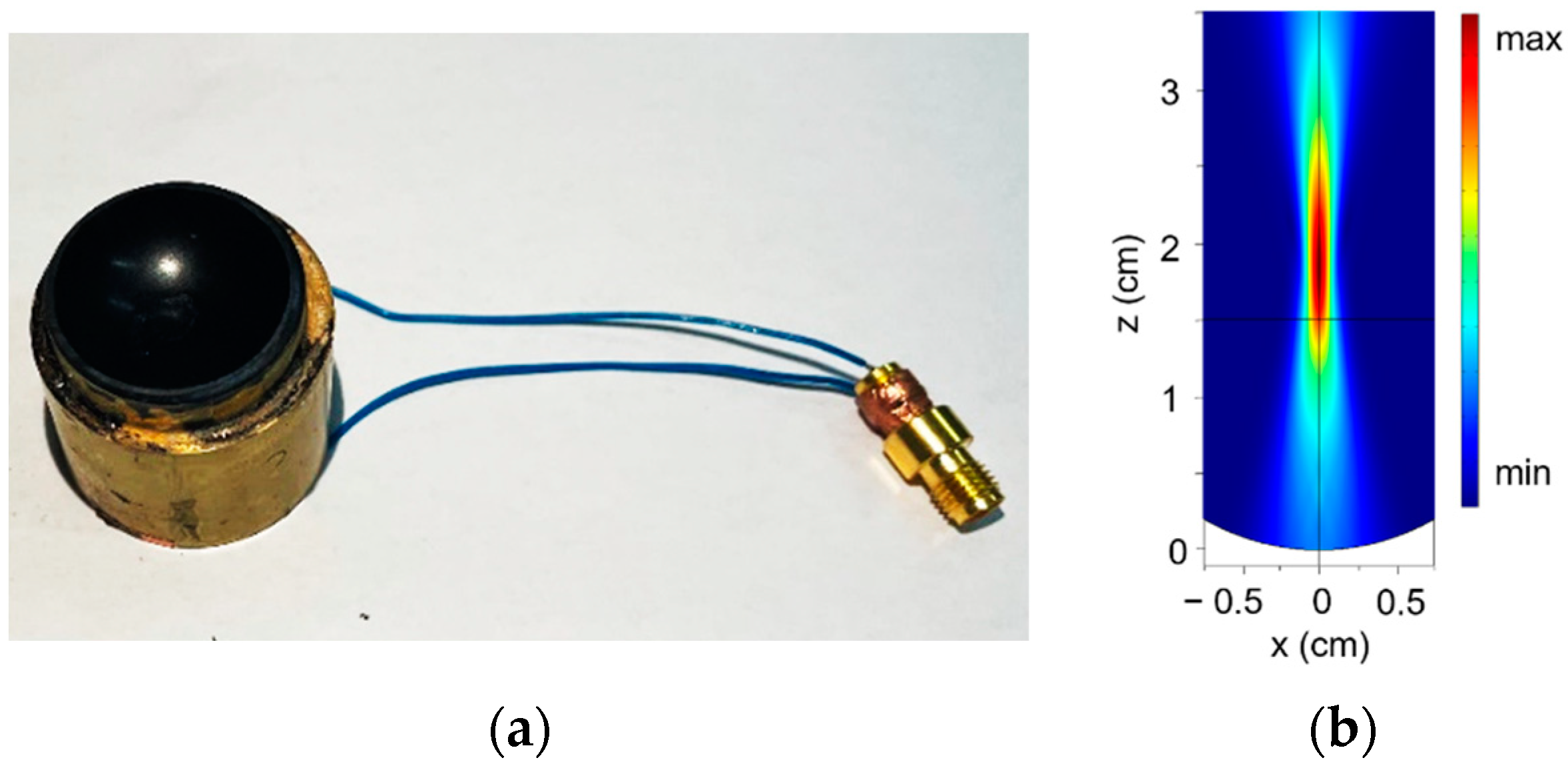
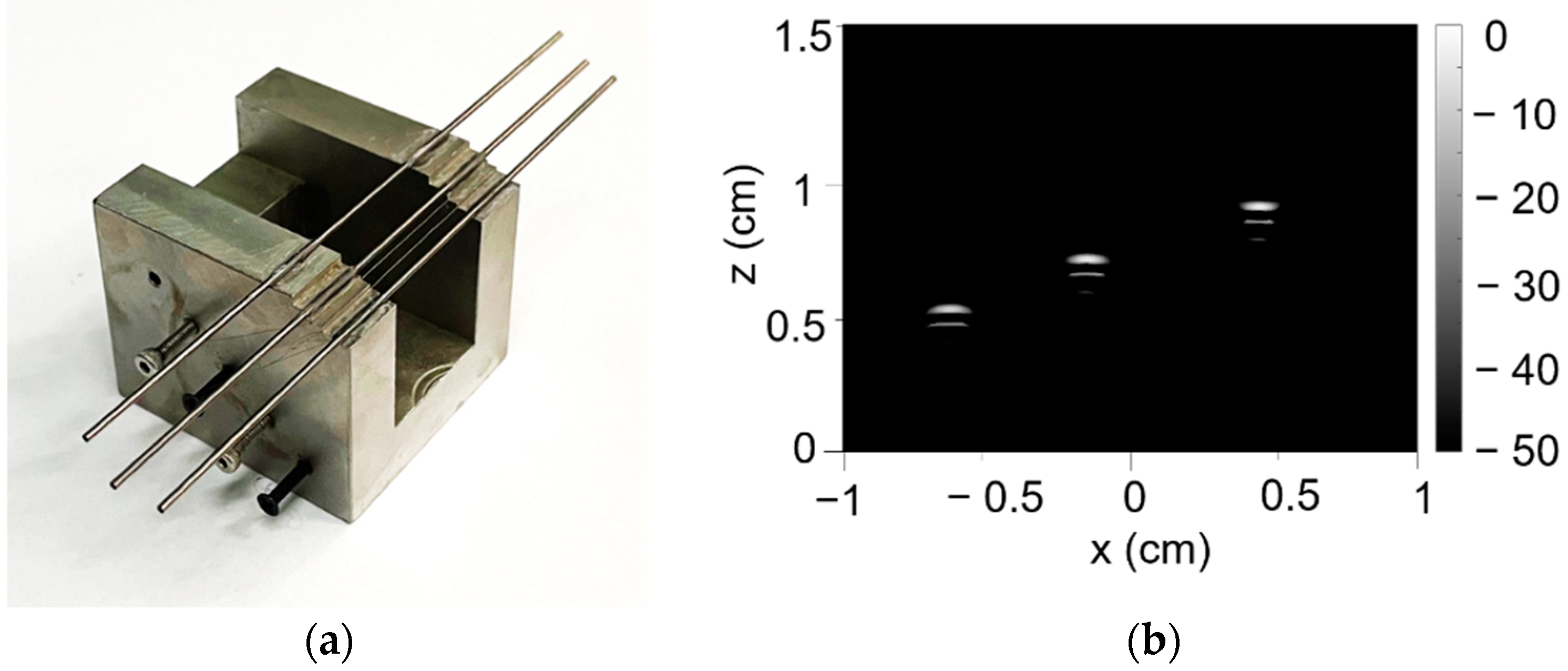
3.2. Imaging of Tungsten Rod Phantoms

To further validate the transducer’s potential for imaging and biological applications, an epoxy focal lens with a 30 mm radius of curvature was added on the surface of the transducer using epoxy, as shown in Figure 10a. The acoustic field of the transducer with an epoxy lens in water was simulated by COMSOL Multiphysics, as shown in Figure 10b. It can be seen from Figure 10b that the focal point of the transducer is located at 19 mm from the bottom of the lens.
As shown in Figure 11a, the tungsten rods with a diameter of 1 mm were placed on different steps with a height interval of 1.5 mm. Figure 11b shows the image of the tungsten rods phantom. The position of the tungsten rods can be seen clearly, which indicates that the fabricated transducer has a good imaging performance.
Furthermore, polystyrene spheres (PS) with a diameter of 300 μm were selected for acoustic tweezer measurements. The signal emitted by the SMB 100A Signal Generator (Rohde Schwarz, Munich, Germany) is amplified by the power amplifier. The signal from the function generator is 10 sine cycles of 3 MHz frequency, and the peak-to-peak voltage is 20 mV. Figure 12 is a schematic diagram of acoustic tweezers. The transducer was fixed on the acoustic tweezer platform, and an inverted microscope at the bottom of the transducer was used to observe the movement of the PS.
Figure 13 shows the motion process of the PS from the starting point and moving to complete a rectangular loop. The PS is captured by the acoustic radiation force and moves along the moving direction of the transducer. Imaging and acoustic tweezer experiments demonstrate the excellent performance of the transducer and the effectiveness of the optimization method.

4. Discussion

To protect the environment, the Restriction of Hazardous Substances Directive (RoHS) has been implemented to minimize the use of toxic materials such as lead in end products. Lead-free piezoelectric materials should be used in more applications. Novel lead-free BNT-6BT piezoelectric ceramics were used to prepare ultrasonic transducers. In our previous work, several BNT-based ultrasonic transducers were reported. In 2013, BNT composite films with a thickness of ~11 μm were used to fabricate ultrahigh-frequency ultrasonic transducers [24]. In 2018, 30 MHz high-frequency ultrasonic transducers were prepared using 70 μm BNT-based thick films [9]. In this work, to further improve the properties of transducers and overcome the difficulty of design, an intelligent optimization algorithm and KLM model were used to optimize the design of transducers. Moreover, the acoustic tweezer is one of the most important applications for ultrasonic transducers, and could be used in non-contract manipulation of microparticles and cells. This is the first time that BNT-based ceramics have been used in acoustic tweezers. However, the electromechanical coupling coefficient kt of piezoelectric materials is the most important parameter of transducers. For BNT-6BT ceramics, the kt is about 0.35, which is not a high value for transducer applications. Thus, the bandwidth and sensitivity of the transducers could be further improved if there is a high kt value of BNT-6BT ceramics. Composite structures could be introduced to BNT-6BT ceramics to improve the kt of piezoelectric materials.

5. Conclusions

Lead-free BNT-6BT-ceramics-based ultrasonic transducers were designed and simulated using an intelligent optimization algorithm and the KLM model-based software, PiezoCAD. The center frequency of the fabricated transducer was 3.03 MHz and the −6 dB bandwidth was 60.3%, which was consistent with the design parameters. The precision and effectiveness of the transducer design was verified based on the intelligent optimization algorithm. To verify potential applications of the transducer, imaging and acoustic tweezer tests were carried out. With an epoxy focal lens added, the tungsten rods phantom imaging of the BNT-6BT transducer was measured. Furthermore, polystyrene particles with a diameter of 300 μm were captured and manipulated using the transducer, which indicates that BNT-6BT lead-free piezoelectric ultrasonic transducers possess a potential application in particle control and the drug delivery field.

Supplementary Materials

The following supporting information can be downloaded at: https://www.mdpi.com/article/10.3390/cryst12081181/s1, Table S1: Orthogonal design of ultrasonic transducer.

Author Contributions

Conceptualization, Y.Q. and J.Z. (Junshan Zhang); methodology, J.Z. (Jianxin Zhao) and Z.W.; software, Y.L.; formal analysis, J.Z. (Jianxin Zhao); investigation, K.Z.; resources, L.W.; data curation, J.H.; writing—original draft preparation, J.Z. (Junshan Zhang); writing—review and editing, Y.Q. and J.Z. (Jian Zhuang); supervision, W.R.; project administration, W.R.; funding acquisition, Z.J. All authors have read and agreed to the published version of the manuscript.

Funding

This work was supported by the China National Key R&D Program (2020YFC0122100), the Natural Science Fundamental Research Project of Shaanxi Province of China (No. 2021JM253), the “111 Project” of China (B14040), Xijiang Innovation Team Introduction Program of Zhaoqing, and the Fundamental Research Funds for the Central Universities.

Institutional Review Board Statement

Not applicable.

Informed Consent Statement

Not applicable.

Data Availability Statement

Not applicable.
The data presented in this study are available on request from the corresponding author.

Conflicts of Interest

The authors declare no conflict of interest.

References

  1. Uchino, K. Piezoelectric Actuators and Ultrasonic Motors; Springer: Boston, MA, USA, 1996. [Google Scholar]
  2. Mistewicz, K.; Jesionek, M.; Kim, H.J.; Hajra, S.; Kozioł, M.; Chrobok, Ł.; Wang, X. Nanogenerator for determination of acoustic power in ultrasonic reactors. Ultrason. Sonochem. 2021, 78, 105718. [Google Scholar] [CrossRef] [PubMed]
  3. Chen, J.; Fei, C.; Lin, D.; Gao, P.; Zhang, J.; Quan, Y.; Chen, Z.; Yang, Y. A Review of Ultra High Frequency Ultrasonic Transducers. In New Piezoelectric Materials and Devices: Fabrication, Structures, and Applications; Frontiers Media: Lausanne, Switzerland, 2022. [Google Scholar]
  4. Jaffe, B.; Roth, R.S.; Marzullo, S. Piezoelectric properties of lead zirconate-lead titanate solid-solution ceramics. J. Appl. Phys. 1954, 25, 809–810. [Google Scholar] [CrossRef]
  5. Quan, Y.; Ren, W.; Niu, G.; Wang, L.Y.; Zhao, J.Y.; Zhang, N.; Liu, M.; Ye, Z.-G.; Liu, L.Q.; Tomoaki, K. Large Piezoelectric Strain with Superior Thermal Stability and Excellent Fatigue Resistance of Lead-free Potassium Sodium Niobate-Based Grain Orientation-Controlled Ceramics. ACS Appl. Mater. Interfaces 2018, 10, 10220–10226. [Google Scholar] [CrossRef] [PubMed]
  6. Jo, W.; Rödel, J. Electric-field-induced volume change and room temperature phase stability of (Bi1/2Na1/2)TiO3-x mol. % BaTiO3 piezoceramics. Appl. Phys. Lett. 2011, 99, 042901. [Google Scholar] [CrossRef] [Green Version]
  7. Ashura, N.I.; Topolov, V.Y. Lead-free 0–3-type composites: From piezoelectric sensitivity to modified figures of merit. J. Adv. Dielectr. 2013, 11, 2150010. [Google Scholar]
  8. Moya, B.R.; Silva, A.C.; Peláiz-Barranco, A.; Guerra, J.D.S. Structural, microstructural and dielectric characterizations of (Bi0.5Na0.5)TiO3 based lead-free ferroelectric ceramics. J. Adv. Dielectr. 2021, 11, 2140006. [Google Scholar] [CrossRef]
  9. Zhang, J.; Ren, W.; Liu, Y.; Wu, X.; Fei, C.; Quan, Y.; Zhou, Q. Fabrication and characterization of high-frequency ultrasound transducers based on lead-free BNT-BT tape-casting thick film. Sensors 2018, 18, 3166. [Google Scholar] [CrossRef] [Green Version]
  10. Zhao, J.Y.; Zhang, N.; Quan, Y.; Niu, G.; Ren, W.; Wang, Z.; Zheng, K.; Zhao, Y.; Ye, Z.-G. Evolution of mesoscopic domain structure and macroscopic properties in lead-free Bi0.5Na0.5TiO3-BaTiO3 ferroelectric ceramics. J. Appl. Phys. 2021, 129, 084103. [Google Scholar] [CrossRef]
  11. Huang, X.Y.; Gao, C.H.; Chen, Z.G.; Liu, H.P. Influence of Composition on Properties of BNT-BT Lead-Free Piezoceramics. J. Rare Earths 2006, 24, 321–324. [Google Scholar]
  12. Scopelliti, M.G.; Chamanzar, M. Ultrasonically sculpted virtual relay lens for in situ microimaging. Light Sci. Appl. 2019, 8, 565–579. [Google Scholar] [CrossRef] [Green Version]
  13. Zhang, Z.; Xu, J.L.; Yang, L.L.; Liu, S.X.; Xiao, J.J.; Zhu, R.F.; Li, X.B.; Wang, X.; Luo, H.S. Fabrication of angle beam two-element ultrasonic transducers with PMN-PT single crystal and PMN-PT/epoxy 1-3 composite for NDE applications. Sens. Actuators A Phys. 2011, 168, 223–228. [Google Scholar] [CrossRef]
  14. Panda, S.; Hajra, S.; Mistewicz, K.; In-na, P.; Sahu, M.; Rajaitha, P.M.; Kim, H.J. Piezoelectric energy harvesting systems for biomedical applications. Nano Energy 2022, 100, 107514. [Google Scholar] [CrossRef]
  15. Fei, C.L.; Liu, X.L.; Zhu, B.P.; Li, D.; Yang, X.F.; Yang, Y.T.; Zhou, Q.F. AlN piezoelectric thin films for energy harvesting and acoustic devices. Nano Energy 2018, 51, 146–161. [Google Scholar] [CrossRef]
  16. Gudra, T.; Opieli’nski, K.J. Influence of acoustic impedance of mutilayer acoustic systems on the transfer function of ultrasionic airborne transducers. Ultrasonics 2002, 40, 457–463. [Google Scholar] [CrossRef]
  17. Fei, C.L.; Ma, J.G.; Chiu, C.T.; Williams, J.A.; Fong, W.N.; Chen, Z.Y.; Zhu, B.P.; Xiong, R.; Shi, J.; Hsiai, T.K.; et al. Design of matching layers for high-frequency ultrasonic transducers. Appl. Phys. Lett. 2015, 107, 123505. [Google Scholar] [CrossRef] [Green Version]
  18. Yang, X.Y.; Fei, C.L.; Li, D.; Sun, X.H.; Hou, S.; Chen, J.; Yang, Y.T. Multi-layer polymer-metal structures for acoustic impedance matching in high-frequency broadband ultrasonic transducers design. Appl. Phys. 2020, 160, 107123. [Google Scholar] [CrossRef]
  19. Chen, D.; Wang, L.; Luo, X.; Fei, C.; Li, D.; Shan, G.; Yang, Y. Recent development and perspectives of optimization design methods for piezoelectric ultrasonic transducers. Micromachines 2021, 12, 779. [Google Scholar] [CrossRef]
  20. Wan, Z.; Chen, Y.; Huang, S.; Feng, D.D. A modified nonmonotone BFGS algorithm for solving smooth nonlinear equations. Optim. Lett. 2014, 8, 1845–1860. [Google Scholar] [CrossRef]
  21. Huang, S.; Wan, Z.; Deng, S.H. A modified projected conjugate gradient algorithm for unconstrained optimization problems. Anziam J. 2013, 54, 143–152. [Google Scholar]
  22. Krimholtz, R.; Leedom, D.A.; Matthaei, G.L. New equivalent circuits for elementary piezoelectric transducers. Electron. Lett. 1970, 6, 398–399. [Google Scholar] [CrossRef]
  23. Zhou, Q.F.; Lau, S.T.; Wu, D.W.; Shung, K.K. Piezoelectric films for high frequency ultrasonic transducers in biomedical applications. Prog. Mater. Sci. 2011, 56, 139–174. [Google Scholar] [CrossRef] [PubMed] [Green Version]
  24. Yan, X.; Ji, H.; Lam, K.H.; Chen, R.; Zheng, F.; Ren, W.; Zhou, Q.; Shung, K.K. Lead-free BNT composite film for high-frequency broadband ultrasonic transducer applications. IEEE Trans. Ultrason. Ferroelectr. Freq. Control 2013, 60, 1533–1537. [Google Scholar] [PubMed]
Figure 1. (a) XRD pattern, (b) SEM image for the surface morphology of BNT-6BT ceramics.
Crystals 12 01181 g001
Figure 2. Temperature dependance: (a) dielectric constant and loss, (b) P-E hysteresis loops, (c) bipolar S-E hysteresis loops, (d) piezoelectric strains of BNT-6BT ceramics.
Crystals 12 01181 g002
Figure 3. Flowchart of training GA-BPNN.
Crystals 12 01181 g003
Figure 4. Fitness of the developed optimization design method for ultrasonic transducer.
Crystals 12 01181 g004
Figure 5. Optimized design parameters of the ultrasonic transducer.
Crystals 12 01181 g005
Figure 6. Performance parameters of ultrasonic transducer obtained at the optimized design parameters.
Crystals 12 01181 g006
Figure 7. (a) Simulated electrical magnitude and phase angle; (b) pulse-echo wave and frequency spectrum performances of the transducers.
Crystals 12 01181 g007
Figure 8. Fabrication process of the BNT-6BT ultrasonic transducer.
Crystals 12 01181 g008
Figure 9. (a) Measured electrical magnitude and phase angle; (b) pulse-echo wave and frequency spectrum performances of the transducers.
Crystals 12 01181 g009
Figure 10. (a) Fabricated ultrasonic transducer with focal lens; (b) simulated acoustic field diagram of the focused transducer.
Crystals 12 01181 g010
Figure 11. (a) Tungsten rods phantom; (b) image of tungsten rods phantom.
Crystals 12 01181 g011
Figure 12. Schematic diagram of acoustic tweezers.
Crystals 12 01181 g012
Figure 13. Particle with a diameter of 300 μm moving along a specific trace with the order (af).
Crystals 12 01181 g013
Table 1. Design parameters of ultrasonic transducer.
Design ParametersRange
Diameter of BNT-6BT (mm)11, 12, 13, 14, 15, 16, 17, 18, 19
Thickness of BNT-6BT (μm)745, 750, 755, 760, 765, 770, 775, 780, 785
Thickness of Ag-epoxy (μm)155, 160, 165, 170, 175, 180, 185, 190, 195
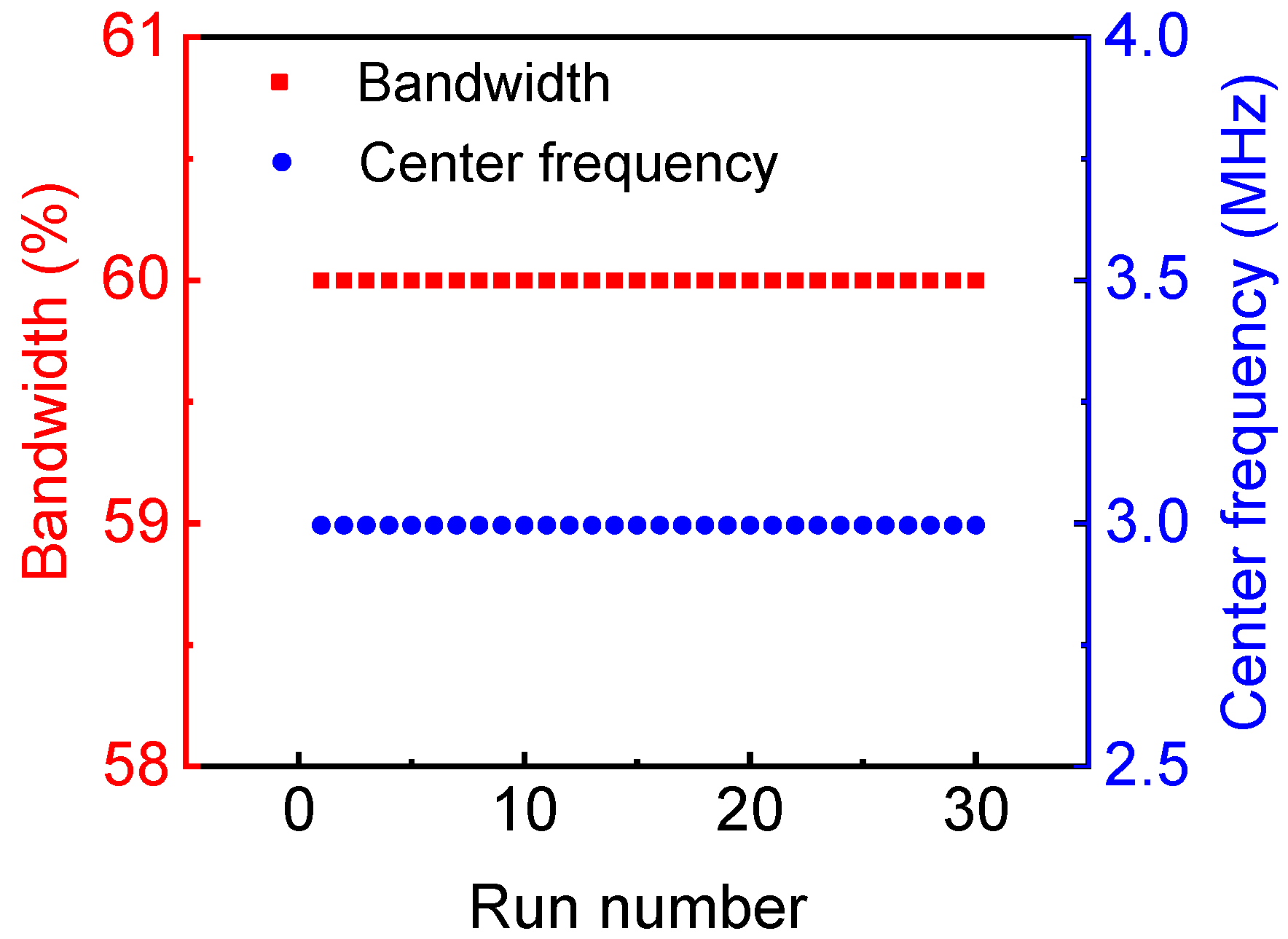
Table 2. Value of design parameters.
ParametertAg-epoxytBNT-6BTDiameterBandwidthCenter Frequency
Mean value176.8766.914.859.992.99
Standard deviation0.00230.00230.00560.0000440.0000035
tAg-epoxy: Thickness of Ag-epoxy; tBNT-6BT: Thickness of BNT-6BT.
Publisher’s Note: MDPI stays neutral with regard to jurisdictional claims in published maps and institutional affiliations.

