Article

The Effect of Different Copper Discs on the Discharge of Superconducting Coils

1
Hefei Institutes of Physical Science, Chinese Academy of Sciences, Hefei 230031, China
2
Science Island Branch, Graduate School, University of Science and Technology of China, Hefei 230026, China
3
The Joint Laboratory on Power Superconducting Technology, China Southern Power Grid Co., Ltd., Guangzhou 510080, China
4
School of Electronic Information and Electrical Engineering, Shanghai Jiao Tong University, Shanghai 200240, China
*
Author to whom correspondence should be addressed.
Crystals 2022, 12(8), 1118; https://doi.org/10.3390/cryst12081118
Submission received: 27 June 2022 / Revised: 25 July 2022 / Accepted: 26 July 2022 / Published: 10 August 2022
(This article belongs to the Special Issue Research on High-Temperature Superconducting Materials)

Abstract

:
High temperature superconducting (HTS) magnets often work at high energy density and have slow quench propagation speed, so a quench will present a serious risk to the safety of magnets. The quench protection method based on the dump resistance can effectively reduce the current and release the energy in the HTS magnets. However, too large dump resistance may cause excessive voltage across the magnets. A quench protection system consisting of dump resistances and metal discs has been proposed. Copper discs are often embedded in HTS magnets for conducting cooling and mechanical support. In the discharging process of HTS magnets, the copper discs can absorb energy from the magnets through magnetic coupling, thus accelerating the current decay of the magnets. This quench protection method is more effective than using dump resistance alone. In this paper, the effect of different copper discs on the discharging process of HTS coils is discussed. Eight types of copper with different residual resistivity ratios (RRR) are applied. The results show that with the increase of the RRR of the copper disc, the current decay rate of the coil increases, and the energy absorbed by the copper disc from the coil increases. The role of different copper discs in the fast quench protection of the coil can be sorted as: RRR = 300 > RRR = 100 > RRR = 80 > RRR = 60 > RRR = 40 > RRR = 30 > RRR = 20 > RRR = 10. The copper disc with RRR of 300 shows the best performance in quench protection of HTS coils.

1. Introduction

The second-generation high temperature superconductor (HTS), ReBCO coated conductor is a very promising material [1,2]. HTS magnets are the primary candidates for manufacturing high magnetic field magnets due to their high critical current and high critical temperature [3,4,5]. However, the quench protection has always been an important problem in the development of HTS magnets in [6,7]. HTS coils often work at a high current density, and the quench propagation rate of insulated coils is low [8,9]. Therefore, when a local quench occurs, a large amount of Joule heat can be generated at the quench region. The generated Joule heat not only presents a serious risk to the safety of HTS magnets, but also affects the cooling system [10,11,12]. A quench protection system which can rapidly reduce the current in HTS coils is required.
Quench protection heaters is an effective active quench protection method [13]. Heating the whole HTS coils to the normal state in a sufficiently short time requires a sufficiently powerful heaters, which is extremely demanding for a quench heater system [14]. Another common active quench protection method is to rapidly reduce the current in HTS coils by using the dump resistance [15,16]. However, in some high-field magnets, too large dump resistance may breakdown the magnets, so the dump resistance is limited to avoid excessive voltage across the magnets [17,18]. Some research has been conducted to overcome this drawback. A quench protection system consisting of dump resistances and copper discs has been proposed [19]. Copper discs often used in HTS magnets for conducting cooling. The copper discs can absorb considerable energy from HTS magnets through electromagnetic coupling, resulting in a rapid current drop at the beginning of discharge [20,21]. This quench protection method is more effective than using dump resistance alone.
During the fast-discharging process of HTS coils, copper discs can accelerate the energy release in the coils, but the effect of copper with different purity on this process may be significantly different. In this paper, the discharging tests based on a dump resistance and a copper disc are performed on a small HTS test coil, which further confirm the acceleration effect of copper disc on the discharge of coil current. Moreover, a finite element model (FEM) is built by COMSOL, which includes a large-scale insulated HTS coil and two copper discs. A series of discharge tests are performed on the coil. Eight types of copper with different residual resistivity ratios (RRR) are applied, and the RRRs of copper are 300, 100, 80, 60, 40, 30, 20, and 10, respectively. In the eight cases of copper with different RRRs, the coil current, energy in the coil, current and temperature of copper discs are compared.

2. Experiment

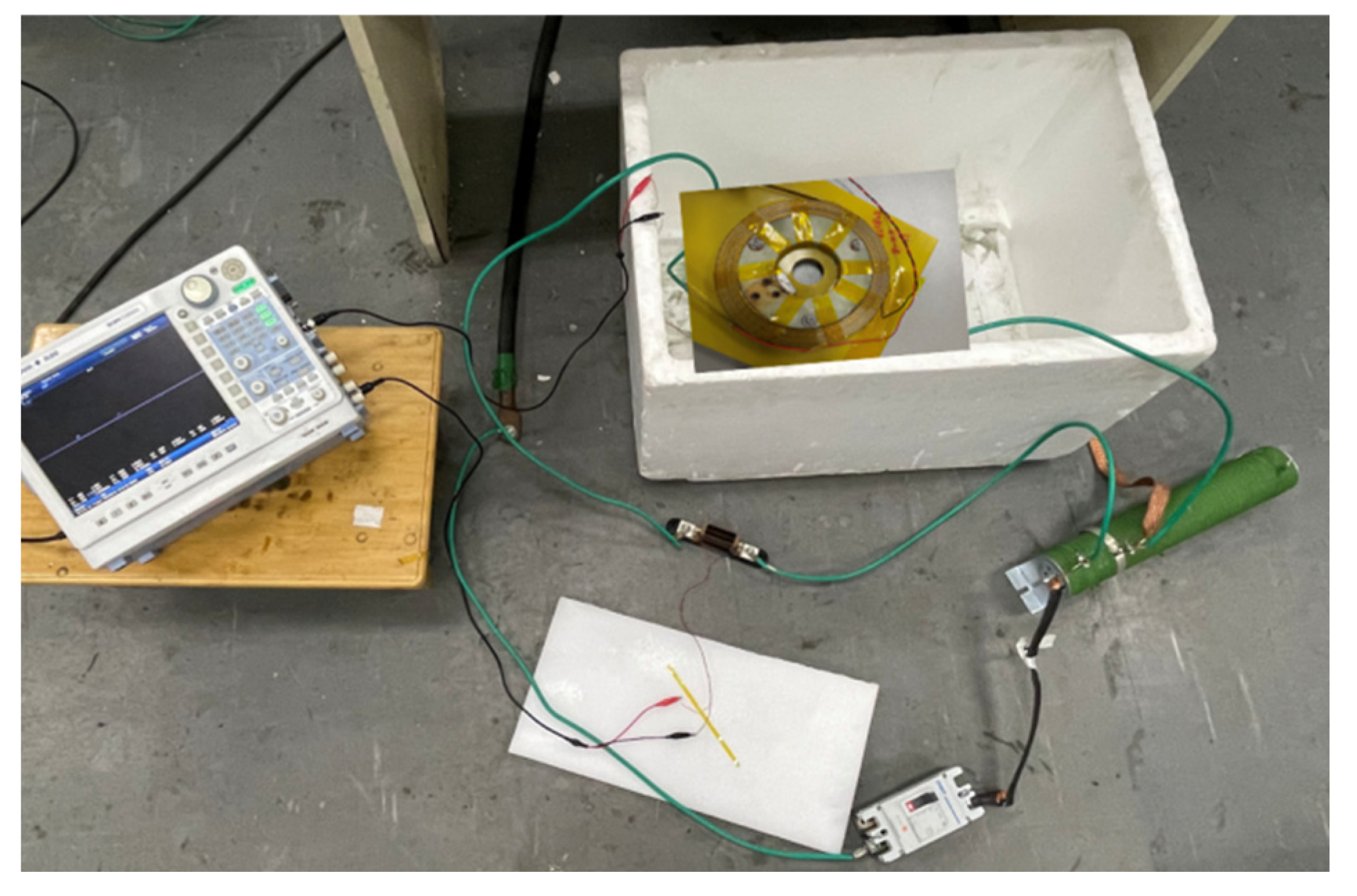
2.1. Experiment Setup

An experimental platform is built to test the effect of copper discs on the fast discharge of HTS coil, as shown in Figure 1. This experimental platform consists of a DC power supply, a sliding rheostat (dump resistance), a switch, an oscilloscope and a small HTS test coil. The coil is an insulated double pancake (DP) coil made of HTS ReBCO tapes from SuNAM, South Korea. The turn-to-turn insulation of the coil is Kapton, and the detailed coil parameters are displayed in Table 1. A copper disc is used in the experiment. The thickness of the copper disc is 2 mm, and the inner diameter and outer diameter are 70 mm and 120 mm respectively.
The HTS test coil and copper disc are tested in liquid nitrogen (77 K). In the tests, the first step is to charge the coil to a preset value using the power supply. After the coil current is stable, the copper disc is placed above the coil. Finally, the power supply is disconnected, and the coil is discharged through the dump resistance. During the discharging process, the current and voltage of the coil are recorded by oscilloscope. The experimental schematic diagram of the discharging process is shown in Figure 2. When the coil is discharged with the dump resistance, the copper disc is magnetically coupled with the coil. In this figure, Rd is the dump resistance, Rc is the resistance of the copper disc, and M is the mutual inductance between the copper disc and the coil.

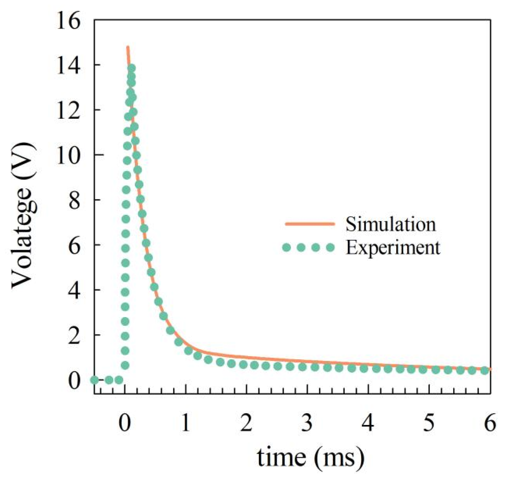
2.2. Experiment Results

Two tests are conducted in the experiment: without and with copper disc. Both discharging tests have the same initial conditions. The initial transport current in the coil is 29.0 A, and the dump resistance Rd is 0.51 Ω. The variation of coil current and voltage during discharging process with and without copper disc are plotted in Figure 3. After the discharge starts, the coil current without copper disc decays exponentially. Compared with the current curve without copper disc, the curve with copper disc decays faster at the initial stage of discharge. The maximum current difference between the two curves happens at t = 1 ms, the coil current with copper disc is 7.2 A, and the coil current without copper disc is 12.9 A. The difference is 19.7% of the initial transport current. The integral of square current of the coil without copper disc is 0.51, and that with copper disc is 0.36, indicating that 29.4% of the energy stored in the coil is absorbed by the copper disc.
Before the discharge starts, the voltage of the coil is zero. At the beginning of the discharge, the voltage generates a high pulse and then gradually decays. The decay trend of coil voltage is the same as that of coil current. The peak of the voltage curve without copper disc is 15.4 V, and the peak of the voltage curve with copper disc is 12.9 V, which is 16.2% lower than that without copper disc.

3. Simulation Model

3.1. FEM Model

To comprehensively study the effect of different copper discs in the discharging process of the coil, a 2D axisymmetric model is built by COMSOL Multiphysics. This model is a FEM model, which consists of an electromagnetic part, a thermal part and a circuit part. The electromagnetic part of the model is applied to all regions, and its input is the current of HTS coil calculated by the circuit part [20]. The electromagnetic part is coupled to the circuit part to simulate the current distribution in the copper discs, and its governing equation is:
× B = μ J B = × A
where B is the magnetic flux, A is the magnetic vector potential, and µ is the permeability. In the thermal part, it is assumed that the copper discs are heated up adiabatically and the input is the eddy current distribution on the copper discs. The governing equation is:
ρ C c T t + ( k c T ) = Q h
where ρ is the density, kc and Cc are thermal conductivity and heat capacity, respectively. The circuit part of the model is used to solve the discharging process of the HTS coil, which is the process after the power supply is disconnected in the experiment. The coil and copper discs are equivalent to ideal inductance elements, and the inductance is constant. First, the circuit equations are listed according to the coupling relationship between the coil and the copper discs, and then solved by the differential algebraic equations (DAEs) in COMSOL. The circuit part obtains the temperature of the copper discs from the thermal part to calculate the equivalent resistance of the copper discs.
According to the parameters in the experiment, a simulation model is built to validate this model. The self-inductance of the copper disc is 1.3 × 10⁻⁷ H, and the mutual inductance between the coil and the copper disc is 5.5 × 10⁻⁶ H. The coil voltages from the experiment and simulation are compared. As shown in Figure 4, the two voltage curves are in good agreement.

3.2. Study Case

The HTS coil used in the simulation is a large-scale insulated DP coil, which is made of ReBCO tapes. The turn-to-turn insulation of the coil is Kapton. The specifications of the large-scale coil are shown in Table 2. The model is shown in Figure 5. Two identical copper discs are distributed in the upper and lower parts of the coil respectively. The thickness of the copper discs is 2 mm, and the inner and outer diameters are the same as those of the coil.
The schematic diagram of the discharging tests of the coil is shown in Figure 6. Mc1 and Mc2 are the mutual inductance between the coil and two copper discs, Mcc is the mutual inductance between the two copper discs. Rd is the dump resistance and Rc is the resistance of the copper discs, which increases with the increase of temperature. In separate simulations, the inductance parameters between the coil and copper discs are calculated using the magnetic energy. The results are shown in Table 3. In the following simulation tests, the initial conditions remain unchanged. The initial temperature is 4.2 K, the initial transport current is 350 A, and Rd is 1 Ω.

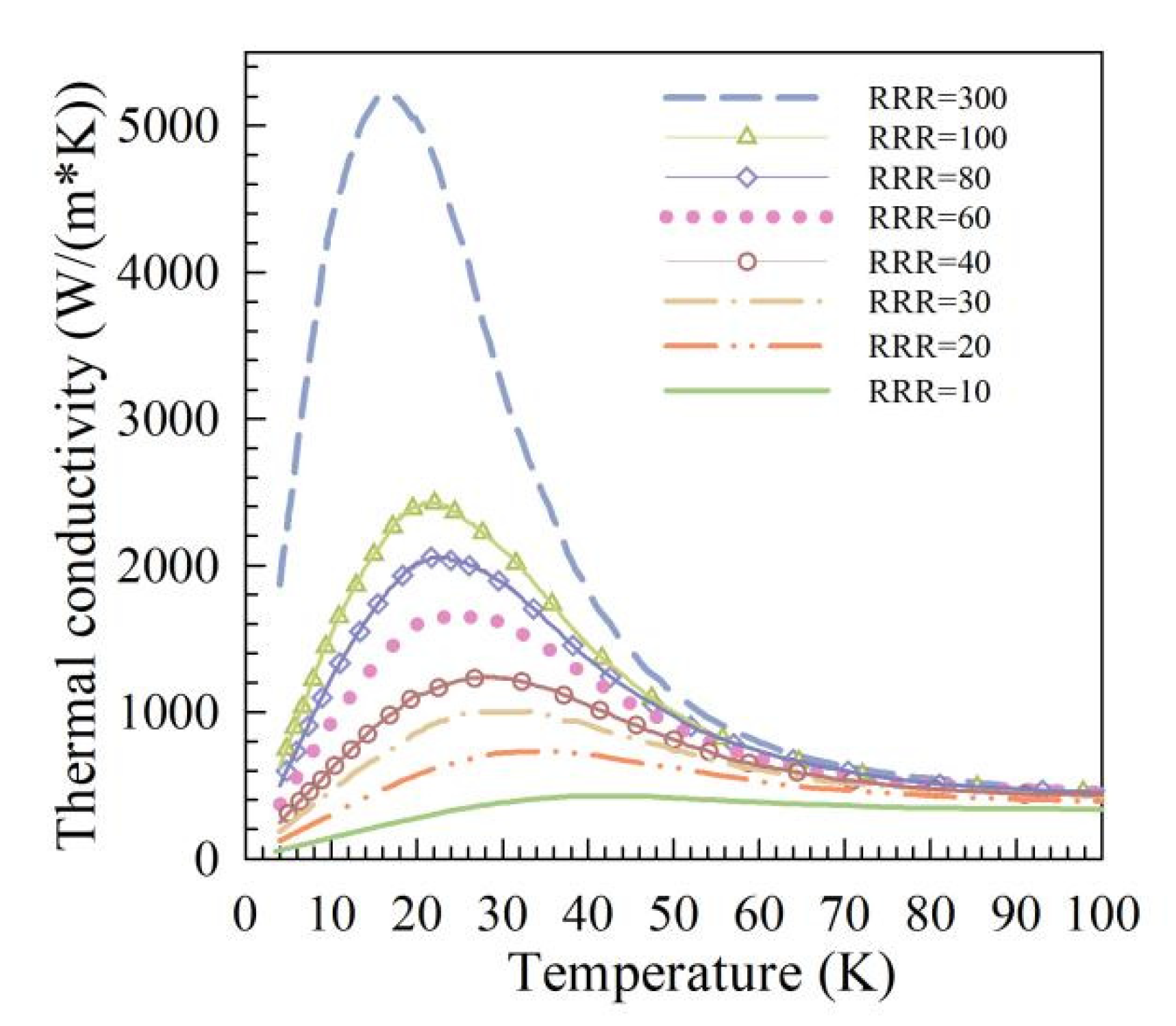
3.3. Material Parameters

In the simulation, the RRRs of different copper discs used is 300, 100, 80, 60, 40, 30, 20, and 10, respectively. The purity of copper discs with different RRRs is different, and their electromagnetic and thermal properties are also different. The electrical conductivity and thermal conductivity of copper with different RRRs are obtained from [22], their variations with temperature are shown in Figure 7 and Figure 8. Copper with different RRRs has an approximate heat capacity, and its variation with temperature is shown in Figure 9.

4. Results and Discussion

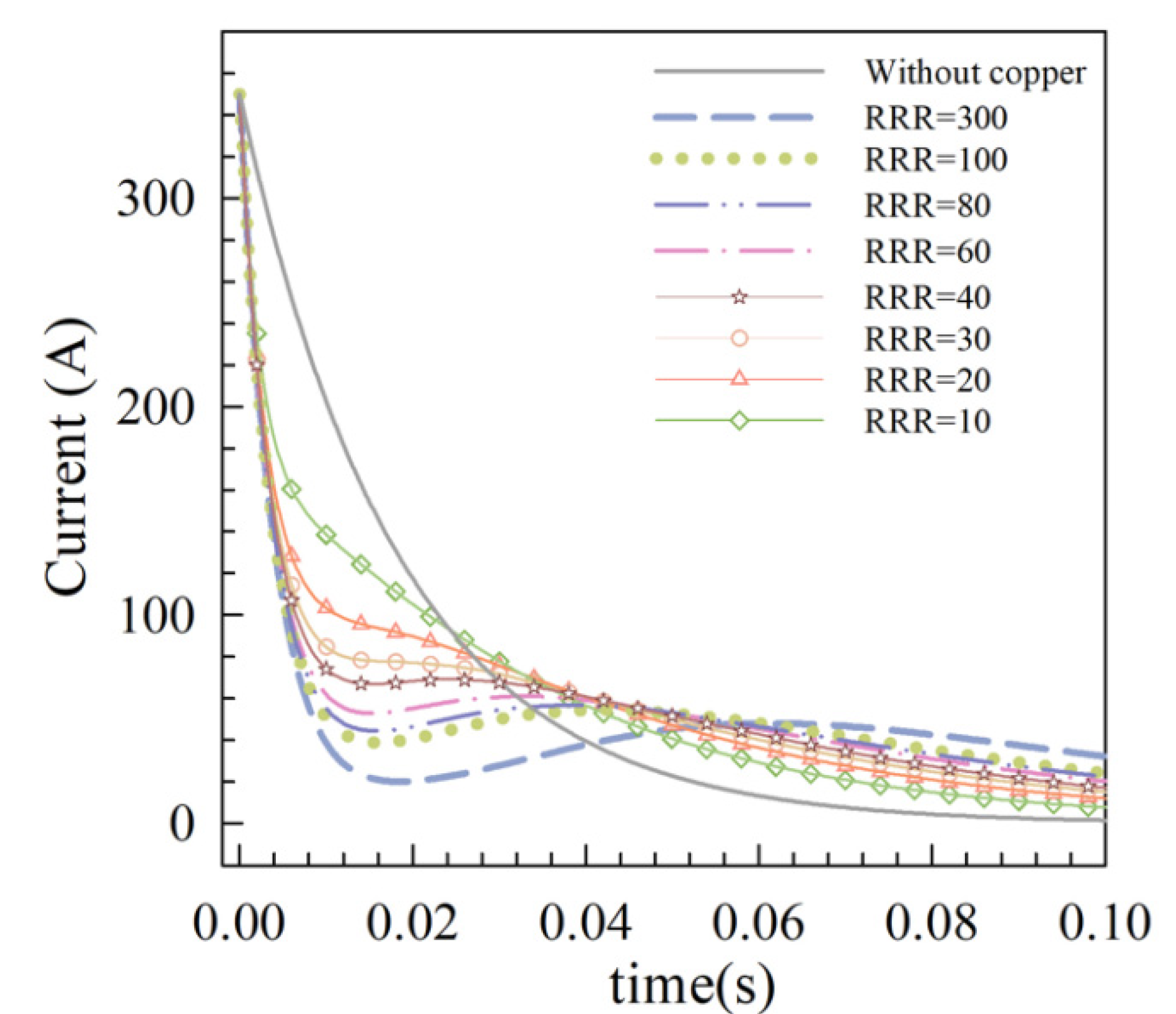
4.1. The Current and Energy in the HTS Coil

Nine discharging tests are performed on the HTS coil, and eight types of copper with different RRRs are applied. The variation of coil current during discharging process is shown in Figure 10. The discharging current of the coil without copper discs follows an exponential decay, and the time constant τ is 18.3 ms. In the case of with copper discs, the coil current has a rapid current drop at the beginning of discharging process, and then the decay rate slows down. When the RRR of copper is high enough, the coil current rebounds after a rapid decay, so there is a current valley in the curve.
The current of coil without copper disc decays by 63.2% in the first τ of the discharge. In the case of copper with RRRs of 10, 20, and 30, the coil current decays by 68.5%, 73.8%, and 77.8%, respectively in the first τ of the discharge. When the RRR of copper is greater than 30, the coil current rebounds after attenuation. In the case of copper with RRR of 40, the current valley happens at t = 15 ms, and the corresponding current attenuation is 283.2 A, which is 80.9% of the initial transport current. In the case of copper with RRR of 60, the current valley occurs at t = 15.5 ms, and the attenuation is 84.9% of the initial transport current. In the case of copper with RRR of 80, the current valley occurs at t = 16 ms, and the coil current is attenuated by 87.3%. In the case of copper with RRR of 100, the current valley also happens at t = 16 ms, and the coil current is attenuated by 88.9%. In the case of copper with RRR of 300, the coil current shows the fastest drop before the valley, which decreases by 94.3% at t = 19 ms. In the discharging process of the coil with different copper discs, the occurrence time of the current valley is similar, which is near the first τ.
Figure 7 shows the variation of the electrical conductivity of copper with different RRRs in the temperature range of 4–100 K. The equivalent resistance of the copper disc is inversely proportional to the electrical conductivity, so the higher the RRR of copper, the lower the resistance of the copper disc. The equivalent resistance of the copper disc decreases, and more eddy currents can be induced in the copper disc during discharging process. Therefore, the higher the RRR of copper, the faster the coil current decays at the beginning of discharging process.
To analyze the flow of energy stored in the HTS coil during the discharging process, this paper calculates the integral of the square current of the coil to the discharge time. The discharge time in this study is 0.1 s. The integral of the square current of the coil in the nine discharging tests and their ratios to the integral without copper discs are listed in Table 4. The energy of the coil without the copper disc is consumed only by the dump resistance Rd. The energy of the coil with the copper disc is consumed by the dump resistance and the copper disc. As shown in Table 4, with the decrease of RRR, the ratio of the integral of square current is gradually increasing. When RRR = 10, the integral with copper disc accounts for 64.3% of the integral without copper disc, and the copper disc only consumes 35.7% of the energy stored in the coil during the whole discharging process. When RRR = 300, the integral ratio is 34.5%, indicating that the energy consumed in the copper disc is 65.5% of the energy stored in the coil, which is 1.8 times that of RRR = 10. With the RRR of copper increases, the energy absorbed by the copper disc from the coil increases greatly. Therefore, the current drop of the coil is steeper at the beginning of the discharging process, and the energy stored in the coil is released faster. It can be concluded that the higher the RRR of copper is, the more effective this technique is for HTS coils.

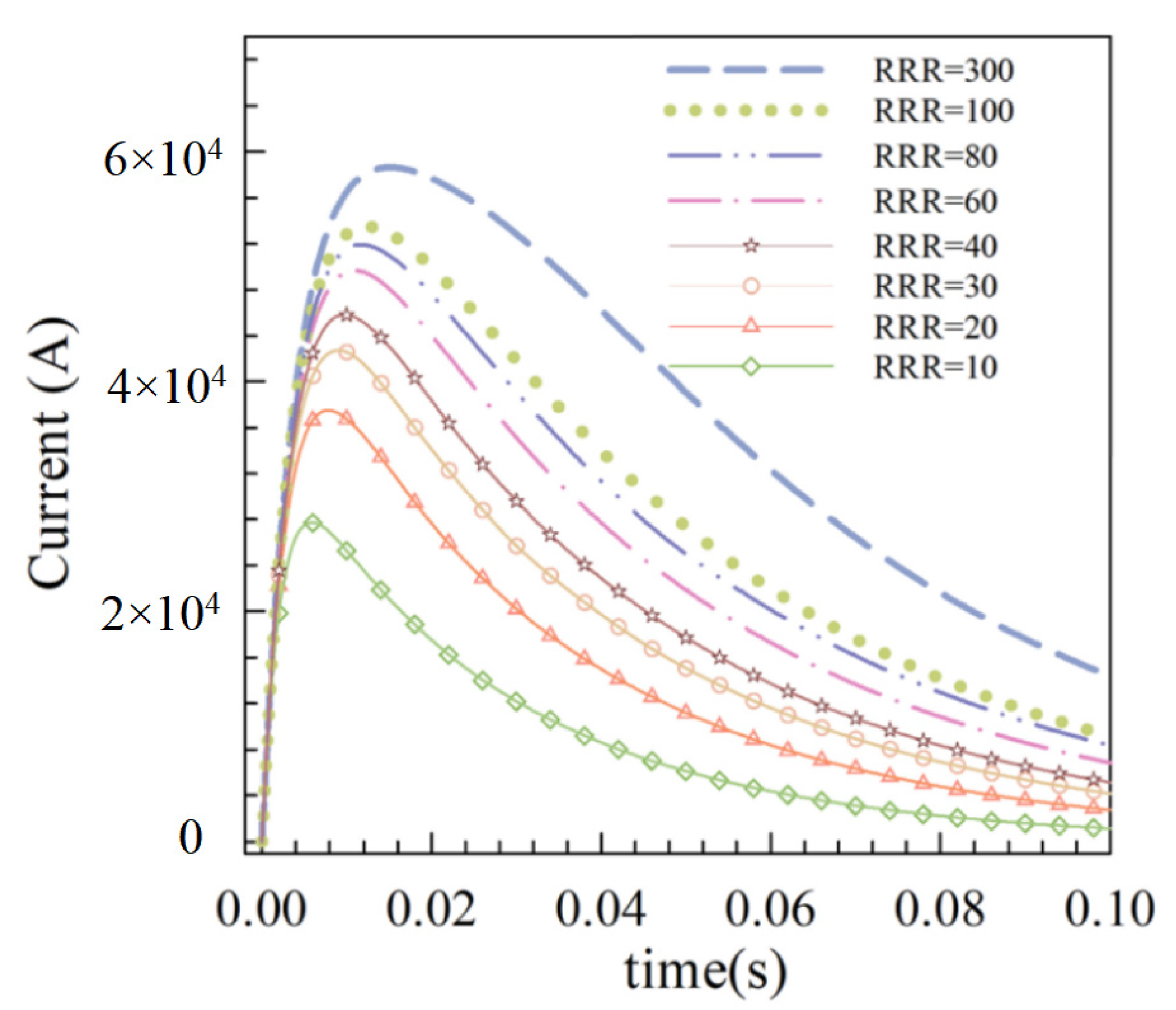
4.2. Current of Copper Discs

As shown in Figure 5, the two copper discs in the model are distributed in the upper and lower parts of the HTS coil. The two copper discs are in a symmetrical position and they have the same size. Thus, the current variations in the two copper discs are the same, as shown in Figure 11. During the discharging process of the coil with different copper discs, the current in the copper disc follows the same trend, first rising rapidly from zero to a peak, then gradually decreasing. At the beginning of the discharge, the copper disc can induce considerable eddy currents by magnetic coupling with the coil. Then, the current in the copper disc flows through its own resistance to produce Joule heat and gradually decreases.
As the RRR of copper increases, the peak current in the copper disc gradually decreases. In the case of RRR = 10, the copper disc has the lowest peak current, 27.7 kA. In the case of RRR = 300, the copper disc has the highest peak current of 58.6 kA, which is 2.1 times that of RRR = 10. This is because the electrical conductivity of copper increases significantly with the increase of RRR in the temperature range of 4–20 K, as shown in Figure 7. The electrical conductivity of copper with RRR of 300 is nearly two orders of magnitude higher than that of copper with RRR of 10, so the peak current induced in the copper disc with RRR of 300 is much higher.

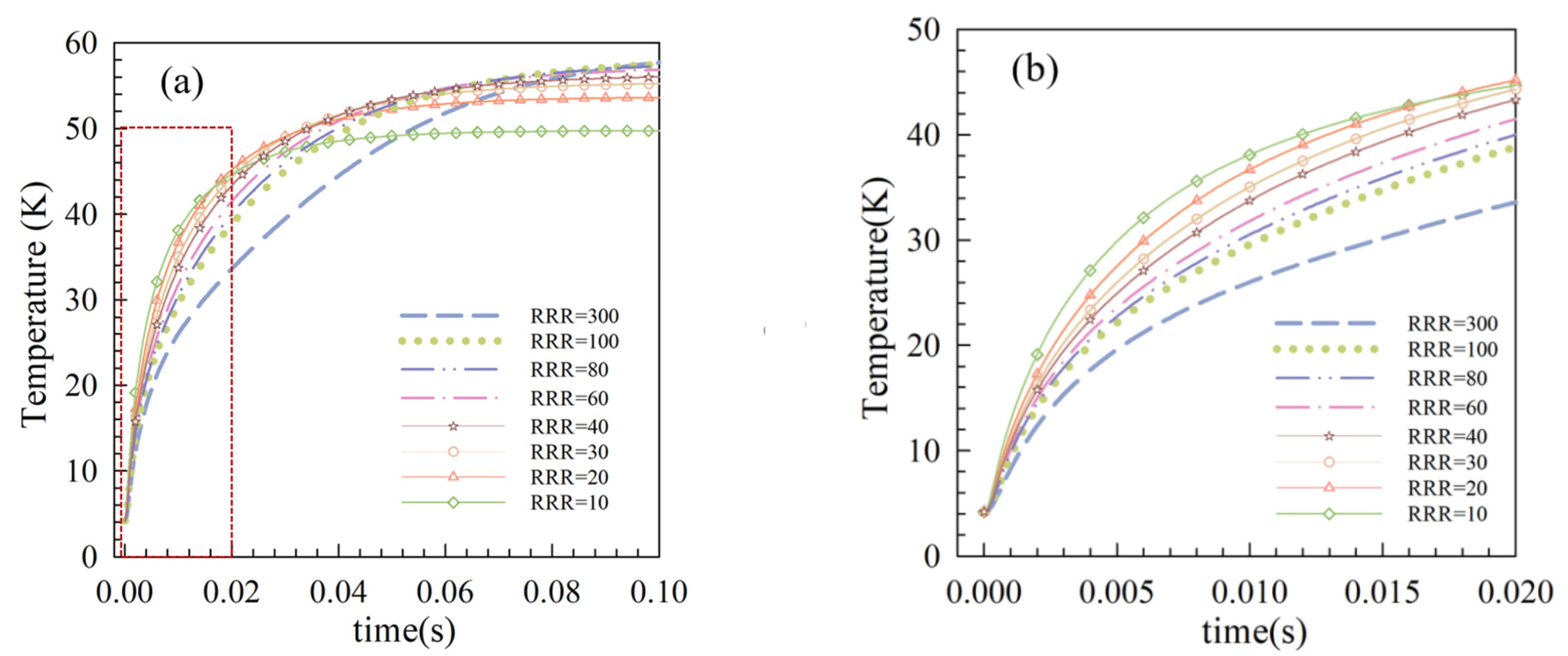
4.3. Temperature of Copper Discs

The current distribution in the two copper discs is the same, so the temperature distribution on the copper discs is the same. During the discharging process, the temperature distribution difference on the copper disc is ignored, and the average temperature on the copper disc is calculated, as shown in Figure 12. Plot (b) shows the partial enlargement of the red dotted area in plot (a). In the early stage of discharging process, the higher the RRR of copper is, the faster the average temperature on the copper disc rises. The copper disc with RRR of 300 has the slowest temperature rise. As the RRR of copper increases, the equivalent resistance of the copper disc decreases significantly, and the temperature rise on the copper disc becomes slower. Therefore, even though the copper disc with RRR of 300 has the largest peak current, the temperature rise is the slowest.
At t = 0.1 s, the average temperature on the copper disc with RRR of 300 is the highest and continues to rise. As the RRR of copper decreases, the final average temperature on the copper disc decreases. When RRR = 10, the final average temperature on the copper disc is 49.7 K. As shown in Figure 7, the difference between the electrical conductivity of copper with different RRRs decreases substantially when the temperature is greater than 20 K. The electrical conductivity of copper with RRR of 300 decays fastest with temperature, so the resistance has the largest increase, and the temperature continues to rise. The electrical conductivity of copper with RRR of 10 has the least obvious attenuation with temperature, so the increase of resistance is small, and the temperature basically remains unchanged after t = 20 ms.

5. Conclusions

In this paper, the effect of copper discs with different RRRs on the discharging process of HTS coils is analyzed by finite element simulation. At the early stage of the discharging process, the acceleration effect of copper disc on the current of the HTS coil is verified on a small HTS test coil. The simulation results show that with the increase of RRR, the acceleration effect of copper discs on the coil current at the beginning of discharge becomes significant, and the copper discs can absorb more energy from the coil. Therefore, the role of different copper discs in the quench protection of HTS coils can be sorted as: RRR = 300 > RRR = 100 > RRR = 80 > RRR = 60 > RRR = 40 > RRR = 30 > RRR = 20 > RRR = 10. The copper disc with RRR of 300 has the best performance in this quench protection technique.

Author Contributions

Conceptualization, Y.X., Y.S. and J.Z.; data curation, Y.X., Z.L.; formal analysis, Y.X. and J.Z., Z.L.; funding acquisition, Y.S. and M.S.; investigation, H.L.; methodology, Y.S. and F.L.; project administration, H.L. and M.S.; resources, Y.S. and M.S.; supervision, Y.S.; validation, H.L., Z.L., J.Z. and F.L.; visualization, Y.X., Z.L; writing—original draft, Y.X.; writing—review & editing, Y.X., H.L. and F.L. All authors have read and agreed to the published version of the manuscript.

Funding

This research was funded by the Strategic Priority Research Program of the Chinese Academy of Sciences (CAS) grant number XDB25020200.

Institutional Review Board Statement

Not applicable.

Informed Consent Statement

Not applicable.

Data Availability Statement

Not applicable.

Conflicts of Interest

The authors declare no conflict of interest.

References

  1. Obradors, X.; Puig, T. Coated conductors for power applications: Materials challenges. Supercond. Sci. Technol. 2014, 27, 044003. [Google Scholar] [CrossRef]
  2. Zhao, Y.; Zhu, J.-M.; Jiang, G.-Y.; Chen, C.-S.; Wu, W.; Zhang, Z.-W.; Chen, S.K.; Hong, Y.M.; Hong, Z.-Y.; Jin, Z.-J.; et al. Progress in fabrication of second generation high temperature superconducting tape at Shanghai Superconductor Technology. Supercond. Sci. Technol. 2019, 32, 044004. [Google Scholar] [CrossRef]
  3. Hahn, S.; Kim, K.; Kim, K.; Hu, X.; Painter, T.; Dixon, I.; Kim, S.; Bhattarai, K.R.; Noguchi, S.; Jaroszynski, J.; et al. 45.5-tesla direct-current magnetic field generated with a high-temperature superconducting magnet. Nature 2019, 570, 496–499. [Google Scholar] [CrossRef] [PubMed]
  4. Yoon, S.; Kim, J.; Cheon, K.; Lee, H.; Hahn, S.; Moon, S.H. 26 T 35 mm all-GdBa2Cu3O7-x multi-width no-insulation superconducting magnet. Supercond. Sci. Technol. 2016, 29, 04T04. [Google Scholar] [CrossRef]
  5. Gao, P.; Guan, M.; Wang, X.; Zhou, Y. Electromagnetic-thermal-structure multi-layer nonlinear elastoplastic modelling study on epoxy-impregnated REBCO pancake coils in high-field magnets. Superconductivity 2022, 1, 100002. [Google Scholar] [CrossRef]
  6. Wang, Y.; Chan, W.K.; Schwartz, J. Self-protection mechanisms in no-insulation (RE)Ba2Cu3Ox high temperature superconductor pancake coils. Supercond. Sci. Technol. 2016, 29, 045007. [Google Scholar] [CrossRef]
  7. Bascunan, J.; Hahn, S.; Lecrevisse, T.; Song, J.; Miyagi, D.; Iwasa, Y. An 800-MHz all-REBCO Insert for the 1.3-GHz LTS/HTS NMR Magnet Program—A Progress Report. IEEE Trans. Appl. Supercond. 2016, 26, 4300205. [Google Scholar] [CrossRef]
  8. Bellis, R.; Iwasa, Y. Quench propagation in high Tc superconductors. Cryogenics 1994, 34, 129–144. [Google Scholar] [CrossRef]
  9. Lecrevisse, T.; Chaud, X.; Debray, F.; Devaux, M.; Fazilleau, P.; Juster, F.P.; Miyoshi, Y.; Rey, J.-M.; Tixador, P.; Vincent, B. Quench Propagation in YBCO Pancake: Experimental and Computational Results. IEEE Trans. Appl. Supercond. 2013, 23, 4601805. [Google Scholar] [CrossRef]
  10. Chigusa, S.; Maeda, H.; Taniguchi, Y.; Hayakawa, N.; Okubo, H. Insulation performance of pressurized liquid helium under quench-induced thermal bubble disturbance for superconducting power apparatus. IEEE Trans. Dielectr. Electr. Insul. 1999, 6, 385–392. [Google Scholar] [CrossRef]
  11. Nanato, N.; Tsumiyama, Y.; Kim, S.; Murase, S.; Seong, K.-C.; Kim, H.-J. Development of quench protection system for HTS coils by active power method. Phys. C Supercond. Its Appl. 2007, 463–465, 1281–1284. [Google Scholar] [CrossRef]
  12. Rummel, T.; Gaupp, O.; Lochner, G.; Sapper, J. Quench protection for the superconducting magnet system of WENDELSTEIN 7-X. IEEE Trans. Appl. Supercond. 2002, 12, 1382–1385. [Google Scholar] [CrossRef]
  13. Weijers, H.W.; Hannahs, S.T.; Murphy, T.P.; Markiewicz, W.D.; Gavrilin, A.V.; Voran, A.J.; Viouchkov, Y.L.; Gundlach, S.R.; Noyes, P.D.; Abraimov, D.V.; et al. Progress in the Development and Construction of a 32-T Superconducting Magnet. IEEE Trans. Appl. Supercond. 2016, 26, 1–7. [Google Scholar] [CrossRef]
  14. Bermudez, S.I.; Ambrosio, G.; Bajas, H.; Bourcey, N.; Chlachidze, G.; Troitino, J.F.; Ferracin, P.; Perez, J.C.; Pincot, F.-O.; Ravaioli, E.; et al. Overview of the Quench Heater Performance for MQXF, the Nb3Sn Low-β Quadrupole for the High Luminosity LHC. IEEE Trans. Appl. Supercond. 2018, 28, 4008406. [Google Scholar] [CrossRef]
  15. Li, Y.; Chen, S.; Dai, Y.; Lei, Y.; Song, S.; Ni, Z.; Hu, X.; Yan, L. A Passive Quench Protection Design for the 9.4 T MRI Superconducting Magnet. IEEE Trans. Appl. Supercond. 2013, 24, 4401605. [Google Scholar] [CrossRef]
  16. Song, H. Sudden-Discharge Cycling Characteristics and Millisecond Dynamic Behaviors of a HTS Stainless-Steel Insulated Double-Pancake Coil with Thin Copper Plates. IEEE Trans. Appl. Supercond. 2020, 30, 4702506. [Google Scholar] [CrossRef]
  17. Ravaioli, E.; Datskov, V.I.; Giloux, C.; Kirby, G.; Kate, H.H.T.; Verweij, A.P. New, Coupling Loss Induced, Quench Protection System for Superconducting Accelerator Magnets. IEEE Trans. Appl. Supercond. 2013, 24, 0500905. [Google Scholar] [CrossRef] [Green Version]
  18. Wang, K.; Song, Z.; Fu, P.; Tong, W.; Li, H.; Zhang, X. Structure Optimization of Fast Discharge Resistor System for Quench Protection System. IEEE Access 2019, 7, 52122–52131. [Google Scholar] [CrossRef]
  19. Green, M.A. Various Quench Protection Methods for HTS Magnets. IOP Conf. Ser. Mater. Sci. Eng. 2020, 755, 012134. [Google Scholar] [CrossRef]
  20. Fazilleau, P.; Borgnolutti, F.; Lecrevisse, T. Protection Design for a 10-T HTS Insert Magnet. IEEE Trans. Appl. Supercond. 2016, 26, 4700705. [Google Scholar] [CrossRef]
  21. Witte, H.; Sampson, W.B.; Weggel, R.; Palmer, R.; Gupta, R. Reduction of the Hot Spot Temperature in HTS Coils. IEEE Trans. Appl. Supercond. 2013, 24, 4601904. [Google Scholar] [CrossRef] [Green Version]
  22. Duthil, P. Material properties at low temperature. arXiv 2015, arXiv:1501.07100. [Google Scholar]
Figure 1. Experiment platform for discharging tests of the HTS coil.
Crystals 12 01118 g001
Figure 2. Experimental schematic diagram for discharging tests of the HTS coil.
Crystals 12 01118 g002
Figure 3. The (a) current and (b) voltage of the HTS coil during the discharging process with and without the copper disc.
Crystals 12 01118 g003
Figure 4. The coil voltages from experiment and simulation in the discharging tests with a 2 mm copper disc. Rd is 0.51 Ω, Initial current is 29.0 A.
Crystals 12 01118 g004
Figure 5. Schematic illustration of the HTS DP coil and two copper discs in 2D axisymmetric space.
Crystals 12 01118 g005
Figure 6. Schematic diagram for discharging tests of the HTS DP coil in the simulation.
Crystals 12 01118 g006
Figure 7. Temperature-dependent electrical conductivity of copper with different RRRs.
Crystals 12 01118 g007
Figure 8. Temperature-dependent thermal conductivity of copper with different RRRs.
Crystals 12 01118 g008
Figure 9. Temperature-dependent heat capacity of copper.
Crystals 12 01118 g009
Figure 10. Current of the coil with different copper discs during fast discharging tests. Rd is 1 Ω. The initial transport current is 350 A.
Crystals 12 01118 g010
Figure 11. Current in different copper discs during fast discharging tests.
Crystals 12 01118 g011
Figure 12. Average temperature of the copper discs during fast discharging tests. (a) during 0–0.1 s; (b) during 0–0.02 s.
Crystals 12 01118 g012
Table 1. Specifications of test coil.
ParametersTest Coil
Tape width4 mm
Tape thickness0.25 mm
Average thickness of each turn444 μm
Number of turns, DP27 × 2
Inner/outer diameter80/104 mm
InsulationKapton
Field per Ampere0.7 mT/A
Self-inductance0.4 mH
Critical current of the coil96 A @ 77 K
Table 2. Specifications of the large-scale coil.
ParametersIndustry-Scale Coil
Tape width10 mm
Tape thickness95 μm
Number of turns, DP200 × 2
Inner/outer diameter80/128 mm
Kapton25 μm
Field per Ampere7.4 mT/A
Self-inductance18.3 mH
Table 3. The inductance parameters.
ParametersValues
Self-Inductance of copper disc1.48 × 10−7 H
Mutual-Inductance between two copper discs, Mcc6.10 × 10−8 H
Mutual-Inductance between HTS coil and copper discs Mc1 = Mc23.86 × 10−5 H
Table 4. Energy parameters of different copper discs.
Materials 0 t I 2 d t Ratios
Without copper disc1121.5100%
RRR = 300387.534.5%
RRR = 100436.538.9%
RRR = 80449.340.1%
RRR = 60472.742.1%
RRR = 40510.445.5%
RRR = 30541.648.3%
RRR = 20599.953.5%
RRR = 10721.164.3%
Publisher’s Note: MDPI stays neutral with regard to jurisdictional claims in published maps and institutional affiliations.

