Abstract
Functionally graded materials (FGMs), which constitute a new type of composite material, have received considerable attention in industry because of the spatial gradient of their composition and the microstructure-induced gradient in their material performance, which make them better suited for high-performance multifunctional applications. Additive manufacturing (AM) has become one of the most promising techniques for the manufacture of materials and structures because of its high flexibility. The combination of advanced materials (FGMs) and advanced manufacturing methods (AM) is expected to facilitate the further development of such engineering materials. In this paper, the definition, historical development and material gradient types of FGMs are introduced. The classification, process principle and typical research results of the AM of metal FGMs are summarized and discussed. In particular, the research status of wire and arc additive manufacture (WAAM), which is more suitable for the preparation of large-scale metal FGMs, is reviewed in detail according to the types of FGMs, and a double-wire bypass plasma arc additive manufacturing technique, which is suitable for inducing a gradient along the direction of single-pass cladding, is proposed. On the basis of this summary of the important achievements made to date, future research is proposed.
1. Introduction
Materials are an important basis for human scientific and technological progress and social development, and the development and innovation of advanced materials are the core of modern manufacturing [1]. With the rapid development of the manufacturing industry, traditional homogeneous materials have been unable to meet the sophistication and diversification requirements of component structure and function. For example, different parts of a structure with different densities, thermal expansion coefficients, ferromagnetism, crystal structures, strengths, etc. are needed [2], which has inspired the gradual introduction of FGMs. FGMs are new biomimetic materials with special functions whose chemical composition, microstructure and atomic order change continuously or quasicontinuously along the length, thickness or other specific direction of the materials, and the physical, chemical and mechanical properties of the materials change continuously or quasicontinuously along the same direction [3,4,5]. These materials have strong designability, and the properties and functions of the materials change with the material position to satisfy the complex and diversified structural and functional requirements to achieve wide use in the aerospace, electronic optics, energy engineering, petrochemical engineering, biomedical engineering and other fields [6,7,8,9,10,11,12,13].
FGMs were first discovered by Bever et al. in 1972, and this concept was formally proposed by the Japanese scientists Masayuki Shinano and Toshio Hirai et al. in 1987 in an aerospace project at the National Aerospace Laboratory [5,14,15]. Since then, many researchers have carried out research on FGMs. Traditional methods for preparing FGMs mainly include plasma spraying, chemical vapour deposition, physical vapour deposition, centrifugal casting, powder metallurgy and self-propagating high-temperature synthesis [16,17,18,19,20,21,22,23,24,25,26]. Although these traditional preparation methods have many advantages, they also have many limitations in practical applications. For example, physical and chemical vapour deposition methods can form only surface coatings and are not suitable for forming block coatings, centrifugal casting can produce only cylindrical components, powder metallurgy can produce only relatively simple structures with high porosity and the self-propagating high-temperature synthesis method is limited by material selection. These limitations have become an obstacle to the further development and industrial application of FGMs. It is thus necessary to explore new methods for the preparation of FGMs.
Additive manufacturing (AM), a strategic emerging industry, is rapidly changing the traditional manufacturing mode [27]. AM is a technique based on the principle of discrete stacking, which accumulatively generates three-dimensional entities through continuous physical layer stacking and can better control the components and performance of metal components than any previous metallurgical techniques. This process provides designers with greater freedom to design according to their own needs, achieve higher production speed and maximum material utilization, and produce more personalized products [5]. The common metal AM techniques based on different heat sources (laser, electron beam and arc) and different raw material supplies (powder bed, powder feeding and wire feeding) are derived from a number of technical routes, but most AM techniques work for a single metal material [28,29,30]. The AM techniques of FGMs involves the preparation of a FGM structure with multiple material properties by changing the ratio of the filling materials and process parameters of the accumulation layer. Based on common metal AM techniques, many researchers have reformed/optimized the manufacturing system and carried out extensive research on the AM of metal FGMs with heterogeneous metal materials [31,32,33,34,35,36].
Because the AM for large-scale metal FGMs has wide application potential, the research status of this technique is reviewed in this paper. The types of FGMs prepared by AM in recent years are introduced, and the classification, process principle and typical research results of metal FGM AM are summarized and discussed. In particular, the research status of WAAM, which is more suitable for the preparation of large-scale metal FGMs, is reviewed in detail according to the types of FGMs. Finally, future research is proposed, especially for the WAAM of FGMs.
2. Types of FGMs Prepared by AM
Different from traditional materials, FGMs have the great advantage of material gradients designed according to requirements to achieve functional gradient characteristics. Fundamentally, material gradients are related to changes in material composition and microstructural characteristics. According to the nature of the gradient, material gradients can be divided into four types: fraction gradient, shape gradient, size gradient and orientation gradient, as shown in Figure 1 [5,37]. According to the material, FGMs prepared by AM can be divided into two types: homogeneous materials and heterogeneous materials [38].
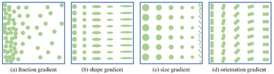
Figure 1.
Various types of gradients in FGMs [5].
Homogeneous materials are obtained by using the same filling material (powder or wire) and adjusting the process or structural design parameters in the AM process, forming a single-phase material with a gradient distribution of microstructural characteristics or macroscopic structure size, which can be divided into four types: solid solution enhancement, grain size, grain orientation and lattice structure [2,38]. Solid-solution-enhancement FGMs (Figure 2a) have the same basic substance phase, and the gradient distribution of solid solution gases is created by the adjustment of the shielding gas composition during the AM process. Grain-size and grain-orientation FGMs (Figure 2b,c) are obtained by adjusting the process parameters during AM, such as heat input, scanning path and scanning rate [38]. Lattice-structure FGMs (Figure 2d) have lattice structure size gradient distributions and are prepared by AM techniques through structural design.
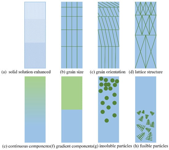
Figure 2.
Schematic illustration of additively manufactured gradient metallic materials [2,38].
Heterogeneous gradient materials are obtained by using two or more kinds of filling material (powders or wires) and adjusting the powder/wire feeding speeds during the AM process, resulting in the formation of a material with a gradient distribution of alloying elements or the second phase, which can be divided into four types: continuous components, gradient components, insoluble particles and fusible particles [2,38]. Continuous-component FGMs (Figure 2e) are gradient materials with a smooth transition of the composition gradient of the multiphase alloy, which is formed by gradually adjusting the feeding speed for two or more kinds of powders or wires during the AM process [38]. Gradient-component FGMs (Figure 2f) are gradient materials with a steep transition of the multiphase alloy composition achieved by adjusting the feeding speed for two or more kinds of powders or wires during the AM process under metallurgy conditions [38]. Insoluble-particle FGMs (Figure 2g) are gradient materials with a volume fraction or size gradient distribution of insoluble particles prepared by adjusting the ratio between insoluble reinforced particles and matrix materials during the AM process. Fusible-particle FGMs (Figure 2h) are gradient materials with volume fraction or size gradient distribution of fusible particles achieved by adjusting the ratio between the dissolved reinforced particles and matrix materials during the AM process.
3. AM Techniques for Metal FGMs
AM has become the most promising and efficient method for the preparation of FGMs due to its discrete-stacking manufacturing concept. At present, common metal AM techniques can be divided into laser AM, electron beam AM and WAAM techniques based on the different heat sources. In this section, their applications in the preparation of FGMs are discussed in turn, with a focus on the WAAM technique, which is suitable for large-scale metal FGM AM.
3.1. Laser AM Techniques for Metal FGMs
The laser AM technique uses a high-energy laser as the heat source and a metal wire or powder as the raw material, stacking the materials layer by layer until finally forming complete parts directly. According to the different methods of raw material supply, this technique can be divided into laser-directed energy deposition (DED) and laser powder bed fusion (LPBF) [39,40,41,42,43]. The laser DED technique uses a laser as the heat source to generate a molten pool in the deposition area moving at a high speed. The raw materials (wire or powder) are directly fed into the high-temperature melt area for rapid melting–solidification, ultimately resulting in complete parts via layer-by-layer deposition, as shown in Figure 3 [44,45]. It can be further subdivided into laser metal deposition (LMD), direct laser metal deposition (DLMD), laser-engineered net shaping (LENS), laser cladding (LC), etc. [46,47,48]. By applying the DED technique, FGMs can be prepared by controlling the feeding rate ratio of two or more kinds of raw materials (powder, wire) or controlling the laser scanning strategy, which is currently the most suitable AM process for preparing metal FGMs [49].
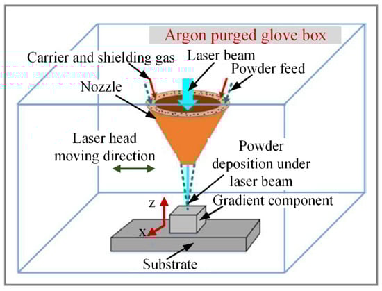
Figure 3.
Schematic of the DED process [45].
Kim et al. [50] used the DED technique and Inconel 718 and SS 316L powders as raw materials, and continuous-component FGMs with a gradient from pure Inconel 718 to pure SS 316L were prepared by controlling the feeding speed of the two powders, as shown in Figure 4. It was found that defects (pores and cracks) caused by ceramic oxides (Al2O3 and TiO2) occurred due to the presence of carbide and intermetallic compounds, and the defects were formed further since the thermal and residual stresses became concentrated at the grain boundaries, causing the constitutional supercooling and columnar-to-equiaxial transition (CET). Bobbio et al. [51] applied the DED technique and selected Ti-6Al-4V powder and prealloyed Invar powder as raw materials to prepare continuous-component FGMs with a gradient from Ti-6Al-4V to Invar 36 (64 wt.% Fe, 36 wt.% Ni). They found that the intermetallic phases (FeTi, Fe2Ti, Ni3Ti and NiTi2) formed in the gradient zone of Ti-6Al-4V and Invar may have led to cracking in the gradient zone, and the composition gradient type was recommended to avoid harmful phases. Zhang et al. [47] adopted the LENS technique and selected austenitic stainless-steel ASS (0Cr18Ni9) powder and martensitic stainless-steel MSS (0Cr16Ni5Mo1) powder as raw materials. Continuous-component FGMs with a gradient from 100% MSS to 100% ASS were prepared with a 25% composition gradient, as shown in Figure 5. It was found that there was no clear preferential orientation for the FGM specimens with different mass fractions, and the grains tended to grow with the increase in austenite (from 100% MSS to 100% ASS); large grains were observed in the regions dominated by austenite (100% ASS, 25% MSS/75% ASS) and the grain size began to grow in the 50% MSS/50% ASS region and the grains were fine-grained with equiaxed grain morphology in the regions dominated by martensite (75% MSS/25% ASS, 100%MSS). The precipitation of α-ferrite in austenite results in a decrease in the ductility of MSS/ASS graded materials. By applying the DLMD technique and using stainless-steel 316L and Inconel 718 powders as raw materials, Reza et al. [52] prepared continuous-component and gradient-component FGMs with a gradient from 100% SS316L to 100% IN718, as shown in Figure 6. It was found that the microstructure morphology alternated between cellular, columnar dendritic and equiaxed dendritic in the building direction, and the coarsest microstructure was observed in the final layers. The element distribution in the continuous-component FGMs changed gradually, while the gradient-component FGMs formed a mixing zone at the interface of SS316L and IN 718, and a gradient was formed due to dilution between the adjacent layers. The gradual distribution of components is beneficial to the mechanical properties of structures. Li et al. [53] prepared continuous-component FGMs with a gradient from Ti2AlNb to TiC + Ti3SiC2 by using Ti, SiC, Si and C powders as raw materials and LC technology. They found that the mixed transition layer of Ti + SiC was mainly composed of TiC and Ti5Si3 and retained the residual Ti-rich phase, and the Ti + Si + C ceramic composite was mainly composed of Ti5Si3, TiC and Ti3SiC2. The mechanical properties increased gradually from Ti2AlNb to TiC + Ti3SiC2. By applying the DED technique and using TC4 powder as the raw material, Zhang et al. [54] obtained solid-solution-enhancement FGMs by changing the composition of the shielding gas. The powder carrier gas was changed from Ar to N2 to produce titanium nitride (TiN) with high hardness when depositing the enhanced region of titanium alloy.
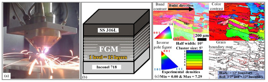
Figure 4.
(a) Photographic image of the LENSTM process, (b) Schematic of the FGMs Inconel 718/SS 316L, (c) EBSD micrographs of the FGM in the defective compositional range of 30 wt.% Inconel 718/70 wt.% SS 316L to 20 wt.% Inconel 718/80 wt.% SS 316L [50].
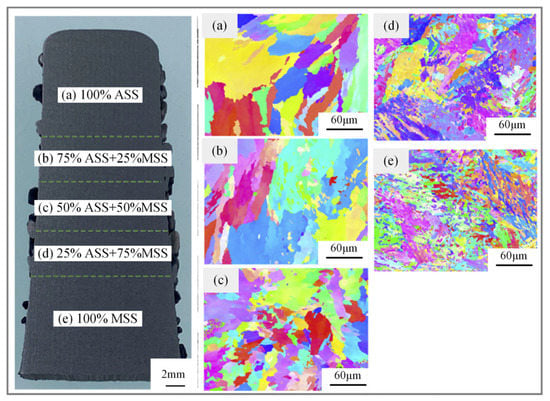
Figure 5.
(a–e) IPF figures of MSS/ASS FGMs for region with different mass fractions [47].
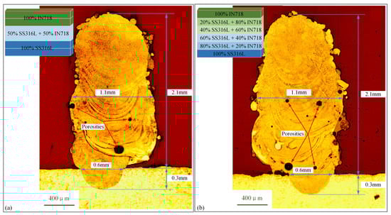
Figure 6.
The cross-section of SS316L/IN718 samples under different gradient types fabricated by DLMD: (a) Composition changed every two layers, (b) Composition changed every one layer [52].
The LPBF technique uses a laser beam under the control of a scanning vibrator to rapidly irradiate the prelaid metal powder layer according to the planned path, resulting in rapid melting and solidification to form a metallurgical cladding layer, and the complete structure is obtained via layer-by-layer cladding. This technique can be further subdivided into selective laser melting (SLM), selective laser sintering (SLS), etc. [55,56]. By applying the LPBF technique, FGMs can be prepared by successively laying powders with different components in the powder bed or adjusting the process parameters, such as the filling method; this method has great advantages in terms of the formation accuracy, surface quality and breadth of applied materials [57].
Narvan et al. [55] selected tool steel H13 powder and vanadium carbide (VC) powder as raw materials and used the LPBF technique to prepare nearly fully compact gradient-component FGMs with a gradient from H13 to VC-H13 (1, 3 and 5 wt.% VC-H13), as shown in Figure 7. It was found that the microstructure of the component was mainly martensite, and V and C existed in the matrix as a supersaturated solid solution, which improved the microhardness, nano-hardness and wear resistance of the component. By applying SLM and using pure iron and Al-12Si powder as raw materials, Demir et al. [58] prepared gradient-component FGMs with a gradient from pure iron to Fe/Al-12Si (55v %Fe and 45v % Al-12Si) to pure Al-12Si, as shown in Figure 8. It was found that the microhardness of the Fe/Al-12Si region was significantly higher than those of pure Fe and pure Al-12Si due to the generation of the intermetallic compound FeAl in the Fe/Al-12Si region, but the high brittleness of the intermetallic compound FeAl could induce cracks, and the microstructure and properties of FGMs could be improved by adjusting the process parameters, such as laser power. Niendorf et al. [56] prepared AISI316L FGMs with different grain sizes and grain orientations by using different laser powers in different areas during the AM process by applying SLM, as shown in Figure 9. They found that fine crystals were present in the 400 W laser region and columnar crystals were present in the 1000 W laser region. The corresponding texture also varied considerably, and the <001> fibre strength of the columnar crystals was greater than that of the fine crystals.
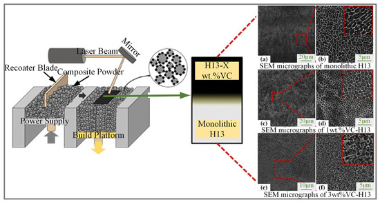
Figure 7.
Schematic of LPBF [55]. (a) Overview of SEM micrograph for monolithic H13 (b) high-magnification image of the dashed square shown in (a), (c) Overview of SEM micrograph for 1wt.%VC-H13, (d) high-magnification image of the dashed square shown in (c), (e) Overview of SEM micrograph for 3wt.%VC-H13, (f) high-magnification image of the dashed square shown in (e) [55].
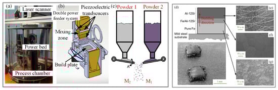
Figure 8.
(a) Schematic of the SLM, (b) Design of the powder feeder system, (c) Schematic of the powder feeder for mixing powders, (d–g) Sample and the cross-sections of different layers of FGMs with pure Fe/Al-12Si [58].
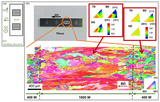
Figure 9.
(a) Schematic of employing two different laser sources within one sample to obtain FGMs, (b) Microstructure analyses for FGMs [56].
3.2. Electron Beam AM Techniques for Metal FGMs
The electron beam AM technique uses a high-energy-density electron beam as a heat source, and wire or powder as raw materials; these materials are placed in a vacuum environment and deposited in a preplanned path to produce complete parts [59,60]. This technique can be further subdivided into electron beam formation (EBF), electron beam selective melting (EBSM), etc. [36,61]. The electron beam AM technique can be used to fabricate FGMs by controlling the ratio of two or more raw materials, which has great advantages in the AM of refractory metals and active metals at high temperatures.
By applying EBSM, Guo et al. [62] used Ti6Al4V and Ti47Al-2Cr2Nb powders as raw materials to prepare gradient-component FGMs with a gradient from Ti47Al2Cr2Nb to Ti6Al4V. The brittle material Ti47Al2Cr2Nb and the plastic material Ti6Al4V were combined, which is difficult to achieve using traditional processes. It was found that the γ-TiAl was formed on the Ti47Al2Cr2Nb side and a coarse basket-weave microstructure was formed on the Ti6Al4V side. The thickness of the interface layer without cracks was approximately 300 µm, and Ti and Al were distributed in a stepped manner at the interface. Hinojos et al. [63] selected IN718 powder and 316L SS powder as raw materials and applied EBSM to prepare gradient-component FGMs with gradients from IN718 to 316L SS and from 316L SS to IN718. It was found that the preferred direction of the grains growing was the <001> direction and the grains in the fabricated material were growing epitaxially in a columnar fashion. The abundance of NbC and the sparse amount of low-melting-point phases indicated that the thermal process at the interface of the two alloys was favourable for their mixing, but the corrosion resistance and brittleness of the fusion zone (FZ) were reduced due to the formation of a large number of carbides and precipitates. Rock et al. [64] adopted EB-PBF and selected pure Mo and titanium carbide (TiC) powders as raw materials to prepare gradient-component FGMs with a gradient from pure Mo to Mo + TiC (the Mo and TiC powders were mixed at a volumetric ratio of 60:40) to pure TiC, as shown in Figure 10. They found that the Mo + TiC solid phase was composed of a mixture of Mo with discrete TiC particles, eutectic Mo + TiC and Mo dendrites (with Ti- and C-rich interdendritic regions), and the unexpected phase in this system could be avoided by accurately controlling the powder input. Based on EBSM and the concept of element evaporation, Zhou et al. [36] used Ti47Al2Cr2Nb alloy powder as a raw material to prepare one-dimensional gradient-component FGMs with a gradient from (α2 + γ) TiAl alloy to (α + β) Ti alloy by controlling the electron beam power, as shown in Figure 11. It was found that α2, α and β phases formed in the interface transition zone (ITZ) of the FGMs. The interface transition zone (ITZ) mainly consisted of non-uniform basket-weave structures when the overlap was 0.5 mm, and ITZs mainly consisted of fine basket-weave structures when the overlaps were 1.0 mm and 2.0 mm. The (α + β) Ti alloy mainly consisted of lamellar and basket-weave (α + β) structures with a small α number when the overlap was 0.5 mm and 1.0 mm, and completely consisted of lamellar and basket-weave (α + β) structures when the overlap was 2.0 mm.
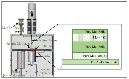
Figure 10.
(a) Schematic of the secondary feeder in EB-PBF, (b) Schematic of Mo–Mo + TiC–Mo sandwich sample [64].
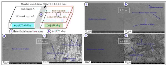
Figure 11.
Schematic of the fabrication of FGMs by EBSM and the microstructure for different zones [36].
Utyaganova et al. [65] adopted the electron-beam wire-feed additive technique (EBWAM) with Al-Mg alloy 5356 (AA5356) wire as the raw material and deposited AA5356 on an AA7075 (Al-Zn-Mg-Cu Alloy 7075) substrate to form gradient-component FGMs. They found that the Mg content gradually increased and the Cu and Zn contents gradually decreased in the transition region, and the microstructure changed from a thick intergrain intermetallic network to a uniform distribution of intermetallic particles. By applying EBWAM, Osipovich et al. [66] used copper C11000 and AISI 304 SS wires as raw materials to prepare continuous-component FGMs with a gradient from 304 SS to Cu, as shown in Figure 12. It was found that the uneven distribution of steel and copper in the gradient region was caused by the solidification and precipitation of copper. With an increase in the copper content, the presence of copper in the gradient region could be divided into three stages: the copper distributed into the iron matrix as a grid, the combination of copper and elements near the dendrite boundary and the formation of secondary-phase Cu and nano-Cu particles precipitated from a supersaturated solid solution of Cu in austenite.
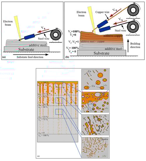
Figure 12.
Schematic of the fabrication of FGMs by EBWAM: (a) SS wire deposition, (b) Copper wire deposition, (c) Microstructural scheme of the evolution of microstructure for the gradient zone [66].
3.3. Wire and Arc AM for Large-Scale Metal FGMs
WAAM uses an arc as the heat source and a metal wire as the raw material to fabricate metal parts layer by layer. According to the form of the arc heat source, this technique can be subdivided into the gas metal arc (GMA) AM technique, gas tungsten arc (GTA) AM technique and plasma arc (PA) AM technique [29,67,68]. By applying the WAAM technique, FGMs can be fabricated by controlling the ratio of the wire feeding speed for two or more wires and other process parameters (shielding gas composition, etc.). Because of its advantages in terms of formation efficiency, formation size and manufacturing cost, WAAM has become one of the most promising manufacturing methods for preparing large-scale metal FGM components.
At present, the FGM components prepared by the WAAM technique can be divided into three types, solid solution enhancement, continuous component and gradient component, among which the multidimensional heterogeneous type is derived based on the gradient component type.
Solid solution enhancement type. Huang et al. [69,70] applied GTA as a heat source and the TiN enhanced phase was generated in situ by adding N2 to the Ar shielding gas (Figure 13). Titanium alloy (TC4) FGMs were fabricated by WAAM with different contents of the TiN strengthened phase in different parts of the structure, which was controlled by the percentage of N2 in the Ar shielding gas. They found that the cladding layers were composed of α-Ti phases and β-Ti phases when no N2 was contained in the shielding gas, and the lamellar α-Ti phase transformed to the TiN phase with particle or dendrite shapes when the percentage content of N2 in the shielding gas increased. The gradually enhanced in situ reinforcement, which was caused by the gradual increase in N2, resulted in a gradient distribution of the composition and microstructure, and the Vickers hardness and compressive strength of the titanium alloy were enhanced. Huang et al. [33] applied GTA as the heat source and Ti6Al4V alloy wire as the raw material, and changed the ratio of TiOx and TiC phases in the cladding layer by controlling the content of CO2 gas in the shielding gas with the other parameters held constant. The cladding layer was mainly composed of lath, a small amount of basket-woven α + β grains and coarse α, and the TiOx and TiC phases gradually increased with the increase in CO2 flow rate.
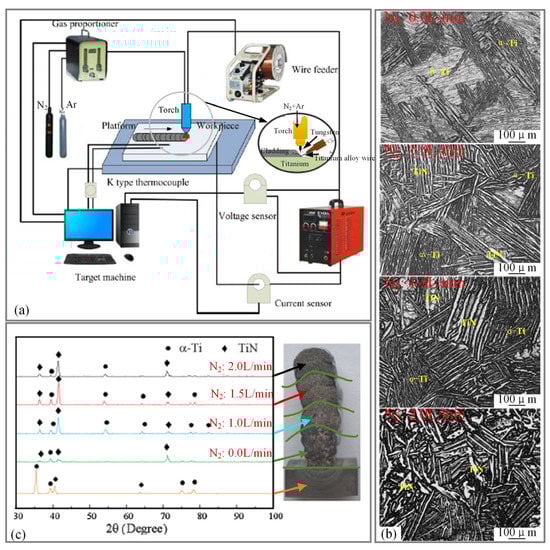
Figure 13.
(a) Schematic of the GTA-AM system [69], (b) Microstructure of the cladding layer with different nitrogen flow rates [69], (c) XRD patterns of base material and individual layers [70].
Continuous component type. Shen et al. [71] used a double-wire arc AM system (Figure 14a) based on the GTA-AM technique and selected 99.5% purity annealed iron wire and 1080-grade aluminium wire as raw materials. Continuous-component FGMs with a gradient from Fe to FeAl and aluminium contents from 0 to more than 50% were fabricated. It was found that the Fe-rich large columnar grains were present at the bottom, the Fe-rich equiaxed grains were present in the upper section and Al-rich lump-shaped grains were present at the very top; the grains in the sample showed an epitaxial growth trend, as shown in Figure 14b. The actual composition presented a smooth transition, rather than the designed ladder composition curve. By applying the GTA-AM technique, Wang et al. [72] used pure titanium wire and pure aluminium 1080 wire as raw materials and successfully prepared continuous-component FGMs with a gradient from pure Ti to Ti-50 at % Al, as shown in Figure 15 and Figure 16. With an increase in the Al content along the gradient direction, the bulk exhibited a layered structure consisting of α–β duplex structure, α-α2 lamellar structure, large α2 grains, α2-γ duplex lamellar structure and γ interdendrite structure in sequence from the bottom to the top. Chen et al. [73] prepared continuous-component FGMs with a gradient from TC4 to 316L by using TC4 and ER-316L wires as raw materials and the GTA-AM technique. They found that cracks appeared on TC4-316L FGM components when the iron content reached 50%, and the microstructure evolution with increasing iron content was as follows: α-Ti + FeTi → Fe2Ti + FeTi + Cr2Ti → Fe2Ti + Cr2Ti. By applying the GTA-AM technique, Lu et al. [74] used TA1 and Inconel 625 wires as raw materials to prepare continuous-component FGMs with a gradient from TiA1 to Inconel 625 by WAAM. It was found that the microstructure changed from α-Ti + β-Ti + NiTi2 to β-Ti + NiTi2 + NiTi, NiTi + Ni3Ti + (Cr, Mo) and γ-Ni + NiTi + Ni3Ti + Laves + (Cr,Mo), and the microhardness of the FGMs changed significantly with changing composition. Chen et al. [75] used 99.9% purity iron (FE005180 grade) and nickel (NI005171 grade) wires as raw materials and adopted the GTA-AM technique to prepare continuous-component FGMs with a gradient from Fe to Fe3Ni. They found that Fcc-Fe3Ni and Bcc-α-Fe were present in the Fe-Fe3Ni FGMs and that Bcc-α-Fe dissolved in the Fe3Ni matrix after heat treatment. Gao Jia [76] developed the auxiliary wire-feeding GMA-AM technique and selected H08Mn2SiA and H06MnNiCrMoA wires as raw materials to prepare continuous-component FGMs by adjusting the main wire-feeding speed, auxiliary wire material and wire feeding speed. It was found that the auxiliary wire feeding speed was inversely correlated with the substrate thermal input and that the maximum melting rate of the auxiliary wire was positively correlated with the total energy/current. EIMER et al. [77] applied the wire laser arc additive manufacture (WLAAM) technique (Figure 17) by using a laser–MIG composite arc as the heat source and adding a second wire. The deposition of an aluminium copper zinc matrix with a continuous change in the zinc content was fabricated by using 2319 aluminium wire and zinc wire as raw materials. A deposition layer with high zinc content and without macroscopic segregation was obtained.
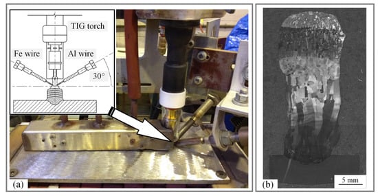
Figure 14.
(a) Schematic of WAAM system, (b) Macrostructure of the cross section of FGMs [71].
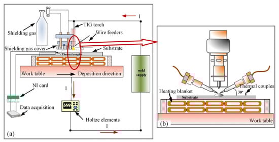
Figure 15.
(a) Schematic of WAAM system, (b) Schematic of double-wire-feeding units [72].
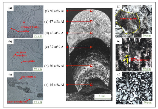
Figure 16.
Microstructure with progressively higher Al content from the bottom to the top [72].
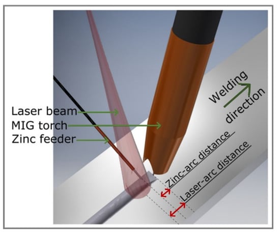
Figure 17.
Schematic of WLAAM [77].
Gradient component type. Dharmendra et al. [78] fabricated gradient-component FGMs with a gradient from 316L stainless steel to nickel–aluminium bronze (NAB) by cladding AWS A5.7 ER CuNiAl wire on a 10 mm-thick 316L stainless steel substrate and applying the GTA-AM technique. They found that the interface did not exhibit any strong texture orientation owing to the control of the thermal gradient and intermetallic Fe3Al was formed at the NAB/SS interface. Coarse and rosette-like κI particles were formed on the NAB side in the first deposited layer only. By applying the GTA-AM technique, Liu et al. [79] used 7055 aluminium alloy wire and 2024 aluminium alloy wire as raw materials to prepare gradient-component FGMs with a gradient from 7055 aluminium alloy to 2024 aluminium alloy, filling the gap in the field of preparation of aluminium-alloy-gradient structural parts [80]. Rodrigues et al. [81] applied the GTA-AM technique and used Er CuAl-A2 (Cu-Al alloy) and ER-120S-G (HSLA steel) wires as raw materials to prepare gradient-component FGMs with a gradient from HSLA steel to CuAl alloy. It was found that the mixture of retained δ-ferrite (BCC) and Cu (FCC) was found in the interface region and no brittle metal phase formed in the interface region. Wu et al. [82] adopted the GMA-AM technique and prepared transverse-gradient component FGMs with a gradient from steel to nickel by adding ER70S-6 steel and ERNi-1 (Ni-3.5 wt.%Ti) nickel wires, as shown in Figure 18. They found that a relatively fine and cellular microstructure was observed on both the Fe and Ni sides, and the dendrite orientation was aligned with the maximum heat flux, which was along the feedstock delivery direction. Additionally, the strength of the interface increased due to the gradient of Fe–Ni solid solution strengthening, which was produced by the intermixing of the Fe and Ni. By applying the GMA-AM technique, Liu et al. [83] used ER70s-6 and SG-CuSi3 wires as raw materials to prepare gradient-component FGMs with a gradient from-low carbon steel to silicon bronze. They found that Cu was not present on the steel side, while Fe entered the bronze side in the forms of particles and large chunks. The interface between the steel and bronze was well bonded without cracks or pores, and metallurgical bonding was achieved. AHSAN et al. [84] adopted the WAAM technique based on the CMT welding process and used ER70s-6 wire and ER316L wire as raw materials. Gradient-component FGMs with a gradient from low-carbon steel (LCS) to AISI 316L stainless steel (SS) were prepared, as shown in Figure 19. The results showed that directional columnar grain growth was shown in the LCS, and the predominant microstructural feature was acicular ferrite in the middle section; the microstructural feature at the inner side was Widmanstatten ferrite along with polygonal and grain-boundary ferrite, and the microstructural feature at the outer surface was fine grains. A vertical columnar growth was shown in the SS, and small columnar dendrites growing toward the surfaces were shown on the inner side and the outer surface. For the interface, acicular ferrite was observed on the LCS side and typical FA transformation microstructure was observed on the SS side. Liu et al. [85] adopted the WAAM technique based on the CMT welding process and selected and prepared gradient-component FGMs with ER80S-G wire as the matrix raw material and OK Tubrodur 15.50 wire as the hard-zone raw material. They found that the structure of the matrix was evenly distributed and consisted of granular bainite, ferrite and carbide particles. The microstructure of each layer in the hard zone differed considerably: the bottom layer was dominated by lamellar tempered martensite, in which the tempered martensite volume decreased and the quenched martensite volume increased with increasing layers, and the last layer was dominated by quenched martensite. Srinivasan et al. [86] adopted the WAAM technique based on the CMT welding process and selected ER70S-6 and ER 2209 wires as raw materials to prepare gradient-component FGMs with a gradient from duplex stainless steel to carbon manganese steel, as shown in Figure 20. The results found that the volume fractions of secondary phases were seen in the microstructure at the carbon manganese steel side, which comprised pearlite, bainite and martensite in the ferrite matrix. Additionally, the formation of martensite in the carbon manganese steel was evident at the interface and in the carbon manganese steel near the interface. A typical solidified duplex stainless steel microstructure with austenitic ferritic grains was observed on the duplex stainless steel side. Miao et al. [87,88] adopted the WAAM technique based on a bypass plasma arc and selected 304 stainless steel wire and S201 red copper wire as raw materials to prepare gradient-component FGMs with a gradient from stainless steel to red copper, as shown in Figure 21. They found that the cladding sequence of copper first, followed by stainless steel, was conducive to formation, and the interfacial layer region was characterized by an α + ε duplex structure.
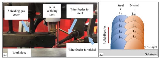
Figure 18.
(a) Schematic of WAAM system, (b) Deposition path patterns [82].
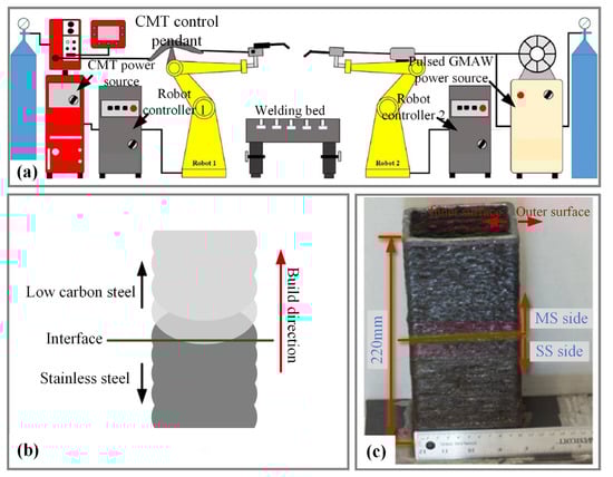
Figure 19.
(a) Schematic of WAAM system, (b) Schematic of FGMs, (c) FGM sample [84].
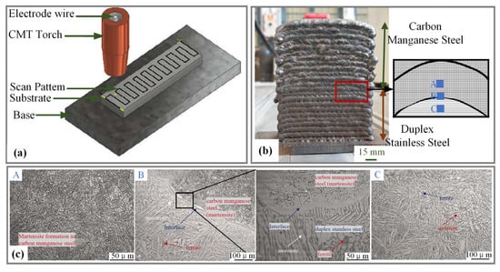
Figure 20.
(a) Schematic of WAAM system based on CMT, (b) Front view of FGM sample, (c) Microstructure at locations A, B and C in figure (b) [86].
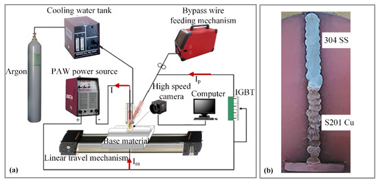
Figure 21.
(a) Schematic of WAAM based on bypass-PA [87], (b) T-section structure of AM [88].
Multidimensional heterogeneous type. Guo [89] adopted double-sided AM based on the CMT welding process and selected ER316L wire and high-nitrogen steel (HNS) wire as raw materials to prepare a 30° interlayer staggered bimetal multilayer interwoven member. Based on the CMT welding process, E [90] adopted the mode with the heterogeneous wires entering the same molten pool and selected ER316L, ER50-6 and HNS wires as raw materials to prepare the multidimensional heterogeneous materials by overlapping cladding of the hard layer with high strength and high hardness (which consisted of stainless steel and low-carbon steel) and the high-plastic soft layer (which consisted of stainless steel and high-nitrogen steel), as shown in Figure 22. There was a large amount of lath martensite and small amounts of ferrite, carbide and austenite in the hard layer, and a large amount of austenite with small amounts of ferrite and nitride in the soft layer. By applying the PA-AM technique, Xu et al. [91] used ER316L stainless-steel wire and ER130SG high-strength steel wire to prepare multidimensional heterogeneous stainless steel/high-strength steel, which adopted a sandwich structure (high strength steel + (one layer, two layers, three layers) stainless steel + high strength steel) and alternating superposition structure (one layer, two layers) high strength steel + stainless steel). They found that there were two transition forms of austenite dendrite transition and martensite structure transition in this part. Guo et al. [92] adopted the PA-AM technique to prepare multidimensional heterogeneous high-carbon steel/high-strength steel by alternating cladding of high-nitrogen austenitic steel wire and 18Ni high-strength steel wire (where the ratio was 1:2, that is, cladding one layer of high-nitrogen austenitic steel and then cladding two layers of high-strength steel), and the angle between the two cladding layers was 90°, as shown in Figure 23. They found that the microstructure of high-nitrogen steel was mainly austenitic isometric and dendrites, and that of high-strength steel was strip martensite. Treutler et al. [93] selected FeNi36 wire and high-strength fine-grained structural steels (DIN EN ISO 16844-AG 69 6M21 Mn4Ni1.5CrMo) as the raw materials, and the FGMs shown in Figure 24 were fabricated by WAAM. They found that the martensitic and austenitic microstructures existed side by side without a pronounced interface region, the martensitic microstructure was observed in the top layer and the tempered martensite was observed in the two layers beneath the top layer.
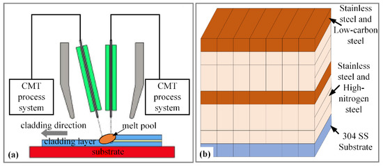
Figure 22.
(a) Schematic of WAAM based on CMT with heterogeneous wires, (b) Schematic of FGMs [90].
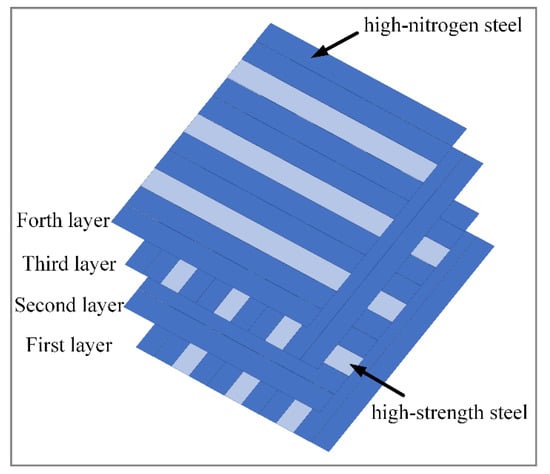
Figure 23.
Schematic of FGMs by PA-AM [92].
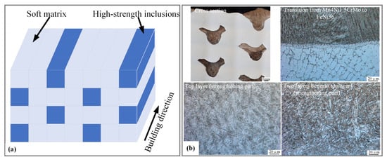
Figure 24.
(a) Schematic for the distribution of layers, (b) Cross section and microstructure of layer structure [93].
It can be seen from the above studies that, although the FGMs prepared by WAAM present different gradient types, the components in each cladding layer are evenly distributed. The authors carried out a systematic study on the properties of a twin-body plasma arc [94,95,96], and the results showed that the heat input of the substrate reduced and the melting amount of the wire increased due to the separation of the wire current from the plasma arc. The amount of wire melting was approximately proportional to the wire current, and the heat input of the substrate was mainly determined by the substrate current. Based on this and by combining the advantages of the plasma arc of high energy density and strong stability, the double-wire bypass plasma arc AM technique, which is suitable for achieving a gradient along the direction of single-pass cladding, was proposed. FGMs whose composition changes along the direction of single-pass cladding were prepared by coordinating each bypass current and controlling the bypass current and wire-feeding speed independently; that is, the change in the material composition gradient for the single-pass cladding occurred along the direction of the single-pass cladding.
A schematic diagram of the double-wire bypass plasma arc AM technique is shown in Figure 25. The main arc supplied by the PAW power supply is established between the tungsten electrode (which is contained in the PAW torch, cathode) and workpiece (anode). One bypass arc supplied by GTAW power supply 1 is established between the tungsten electrode (which is contained in the PAW torch, cathode) and wire 1 (anode). The other bypass arc supplied by GTAW power supply 2 is established between the tungsten electrode (which is contained in the PAW torch, cathode) and wire 2 (anode). The total current (I) includes the main current (I1), wire 1 current (I2) and wire 2 current (I3). Under the premise that I and I1 remain unchanged, the change in the material composition gradient for the single-pass cladding is obtained by the coordinated control of I2 and I3 and the corresponding real-time adjustment of the wire-feeding speed, and the FGMs prepared by this technique are obtained. This will enrich WAAM, which is suitable for metal FGMs, and improve the flexibility of large-scale metal material–structure–function (large-scale metal FGMs) integrated manufacturing.
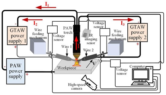
Figure 25.
Schematic of double-wire bypass plasma arc AM.
In summary, the WAAM technique can be used to fabricate FGM parts, and FGMs with different gradient types (solid solution enhanced type, continuous component type, gradient component type and multidimensional heterogeneous type) can be fabricated by changing the wire-feeding speed or shielding gas composition according to the designed material composition. At present, most of the WAAM techniques applied to metal FGMs are based on traditional arc heat sources, namely GMA, GTA and PA. However, with the continuous emergence of novel arc processes/heat sources, the CMT process, laser–MIG composite arc heat source, bypass plasma arc heat source and other arc heat sources have been gradually applied to the WAAM technique for FGMs. The material adaptability will be broadened and the forming quality will be further optimized. Compared with the laser AM technique and electron beam AM technique, the WAAM technique has unique advantages and great potential in the field of large-scale metal material–structure–function integrated manufacturing due to its advantages in formation quality, manufacturing efficiency, material utilization and manufacturing cost. However, it needs to be combined with a mechanical processing technique to avoid the problem of poor formation accuracy.
4. Summary and Future Work
In recent years, studies on metal FGMs have increased, especially FGMs fabricated by the AM technique. In this way, compositional gradient metallurgy allows for the strategic mixing of materials, and a larger material property space is obtained, breaking through the traditional preparation or metallurgical combination of materials. By controlling the shielding gas composition, heat input, input ratio of raw materials and other parameters, FGMs with different gradient types (solid solution enhanced type, grain size type, grain orientation type, continuous component type, gradient component type and multidimensional heterogeneous type) are fabricated by the AM technique, which results in high wear resistance, hardness and other excellent mechanical properties. Defects such as porosity and cracks can be avoided effectively by adjusting the composition of the gradient region and process parameters.
The laser AM technique is one of the earlier techniques for the preparation of FGMs, and it is also one of the techniques that can be applied to a wide range of materials. The WAAM technique was later applied to the preparation of FGMs. It breaks the strict requirements of the environment, part size and part shape in traditional manufacturing methods and laser/electron beam additive manufacturing and integrates the advantages of high efficiency and high adaptability, which has unique advantages in large-scale metal material–structure–function (large-scale metal FGMs) integrated manufacturing.
Research on the preparation of FGMs by the WAAM technique has attracted increasing attention from researchers. Most of the research is about the basic theoretical aspects, such as the microstructure, texture, composition distribution, interface region characteristics and new AM technique of FGMs with a single wall. There have been few engineering application-oriented studies, such as process parameter optimization and engineering preparation of FGM components. In the future, it will be necessary to focus on engineering applications, extend the research from the laboratory to production workshops and seek a process scheme suitable for engineering applications. Making full use of the computer-aided function can play a role in the establishment of a FGM database and the simulation and prediction of the structure and properties of FGMs. It can not only save the cost of materials, but also guide the design and performance optimization of FGMs and help to further expand the application field of FGMs fabricated by the AM technique. Moreover, it is necessary to develop comprehensive material–product–manufacturing principles [13], guidelines and standards for all steps of FGMs fabricated by the WAAM technique to further develop the commercial potential and value of FGMs.
Author Contributions
Conceptualization, R.Z.; methodology, F.J.; software, R.Z.; validation, R.Z.; formal analysis, R.Z.; investigation, R.Z. and J.Y.; resources, R.Z. and J.Y.; data curation, R.Z.; writing—original draft preparation, R.Z.; writing—review and editing, R.Z.; visualization, R.Z.; supervision, L.X.; project administration, R.Z.; funding acquisition, R.Z. and F.J. All authors have read and agreed to the published version of the manuscript.
Funding
This project was supported by the Youth Program of the National Natural Science Foundation of China (Grant No. 51905008), Beijing Postdoctoral Research Foundation (Grant No. 2021-zz-064), the Major Science and Technology Innovation Project of Shandong Province (Grant No. 2020JMRH0504), Jinan Innovation Team Project (Grant No. 2021GXRC066) and Quancheng Scholars Construction Project.
Institutional Review Board Statement
Not applicable.
Informed Consent Statement
Not applicable.
Data Availability Statement
Not applicable.
Acknowledgments
The authors sincerely acknowledge the financial support from the National Natural Science Foundation of China (Grant No. 51905008), Beijing Postdoctoral Research Foundation (Grant No. 2021-zz-064), the Major Science and Technology Innovation Project of Shandong Province (Grant No. 2020JMRH0504), Jinan Innovation Team Project (Grant No. 2021GXRC066) and Quancheng Scholars Construction Project.
Conflicts of Interest
The authors declare no conflict of interest.
References
- Wu, S.; Wu, Z.; Kang, G.; Chen, W.; Li, J.; Ke, L.; Wang, T.; Xiao, T.; Yuan, Q.; Hu, C. Research Progress on Multi-dimensional and Multi-scale High-throughput Characterization for Advanced Materials. J. Mech. Eng. 2021, 57, 37–65. [Google Scholar]
- Hofmann, D.C.; Kolodziejska, J.; Roberts, S.; Otis, R.; Dillon, R.P.; Suh, J.; Liu, Z.; Borgonia, J. Compositionally graded metals: A new frontier of additive manufacturing. J. Mater. Res. 2014, 29, 1899–1910. [Google Scholar] [CrossRef] [Green Version]
- Liu, Z.; Meyers, M.A.; Zhang, Z.; Ritchie, R.O. Functional gradients and heterogeneities in biological materials: Design principles, functions, and bioinspired applications. Prog. Mater. Sci. 2017, 88, 467–498. [Google Scholar] [CrossRef]
- Xue, C.; Song, Z.; Chunhua, Z.; Chenliang, W.; Qiang, W.; Shiyun, D. Research status and prospect of laser additive manufacturing technology for high performance gradient functional materials. J. Mater. Eng. 2020, 48, 13–23. [Google Scholar]
- Sarathchandra, D.T.; Subbu, S.K.; Venkaiah, N. Functionally graded materials and processing techniques: An art of review. Mater. Today Proc. 2018, 5, 21328–21334. [Google Scholar] [CrossRef]
- Gupta, A.; Talha, M. Recent development in modeling and analysis of functionally graded materials and structures. Prog. Aerosp. Sci. 2015, 79, 1–14. [Google Scholar] [CrossRef]
- Domack, M.S.; Baughman, J.M. Development of Nickel-Titanium Graded Composition Components. Rapid Prototyp. J. 2004, 11, 41–51. [Google Scholar] [CrossRef]
- Pompe, W.; Worch, H.; Epple, M.; Friess, W.; Gelinsky, M.; Greil, P.; Hempele, U.; Scharnweber, D.; Schulte, K. Functionally graded materials for biomedical applications. Mater. Sci. Eng. A 2003, 362, 40–60. [Google Scholar] [CrossRef]
- Matsuo, S.; Watari, F.; Ohata, N. Fabrication of a functionally graded dental composite resin post and core by laser lithography and finite element analysis of its stress relaxation effect on tooth root. Dent. Mater. J. 2001, 20, 257. [Google Scholar] [CrossRef]
- Malinina, M.; Sammi, T.; Gasik, M.M. Corrosion Resistance of Homogeneous and FGM Coatings. Mater. Sci. Forum 2005, 492–493, 305–310. [Google Scholar] [CrossRef]
- Kawasaki, A.; Watanabe, R. Thermal fracture behavior of metal/ ceramic functionally graded materials. Eng. Fract. Mech. 2002, 69, 1713–1728. [Google Scholar] [CrossRef]
- Müller, E.; Drašar, Č.; Schilz, J.; Kaysser, W.A. Functionally graded materials for sensor and energy applications. Mater. Sci. Eng. A 2003, 362, 17–39. [Google Scholar] [CrossRef]
- Hsiang, L.G.; Eujin, P.; David, H.; Monzón, M.D. An overview of functionally graded additive manufacturing. Addit. Manuf. 2018, 23, 34–44. [Google Scholar]
- Bever, M.B.; Duwez, P.F. Gradients in Composite Materials. Mater. Sci. Eng. 1972, 10, 1–8. [Google Scholar] [CrossRef]
- Shen, M.; Bever, M.B. Gradients in polymeric materials. J. Mater. Sci. 1972, 7, 741–746. [Google Scholar] [CrossRef]
- Zhu, J.C.; Yin, Z.D.; Lai, Z.H. Fabrication and microstructure of ZrO2-Ni functional gradient material by powder metallurgy. J. Mater. Sci. 1996, 31, 5829–5834. [Google Scholar] [CrossRef]
- El-Galy, I.M.; Ahmed, M.H.; Bassiouny, B.I. Characterization of functionally graded Al-SiCp metal matrix composites manufactured by centrifugal casting. Alex. Eng. J. 2017, 56, 371–381. [Google Scholar] [CrossRef]
- Wan, B.Q.; Sun, X.Y.; Ma, H.T.; Feng, R.F.; Li, Y.S.; Yang, Q. Plasma enhanced chemical vapor deposition of diamond coatings on Cu–W and Cu–WC composites. Surf. Coat. Technol. 2015, 284, 133–138. [Google Scholar] [CrossRef]
- Uribe, E.; Salas, O.; Melo-Máximo, D.V.; Hernández-Durán, P.E.; Oseguer, J.; Torres, R.D. Evolution of PVD Al oxide coatings in carburizing atmospheres at high temperature. Surf. Coat. Technol. 2015, 284, 2–8. [Google Scholar] [CrossRef]
- Khor, K.A.; Dong, Z.L.; Gu, Y.W. Plasma prayed functionally graded thermal barrier coatings. Mater. Lett. 1999, 38, 437–444. [Google Scholar] [CrossRef]
- Kawase, M.; Tago, T.; Kurosawa, M.; Utsumi, H.; Hashimoto, K. Chemical vapor infiltration and deposition to produce a silicon carbide-carbon functional gradient material. Chem. Eng. Sci. 1999, 54, 3327–3334. [Google Scholar] [CrossRef]
- Kotikala, R.; Suresh Babu, V.; Davidson, M.J. Interfacial microstructure and properties of Al-Cu functionally graded materials fabricated by powder metallurgy method. Mater. Today Proc. 2021, 46, 9212–9216. [Google Scholar]
- Gao, J.W.; Wang, C.Y. Modeling the solidification of functionally graded materials by centrifugal casting. Mater. Sci. Eng. A 2000, 292, 207–215. [Google Scholar] [CrossRef]
- Weon, Y.S.; Jongcheon, Y.; Hyub, L.; Sik, S.D. Defect of functionally graded material of inconel 718 and STS 316L fabricated by directed energy deposition and its effect on mechanical properties. J. Mater. Res. Technol. 2022, 17, 478–497. [Google Scholar]
- Wei, C.; Cheng, J.; Zhang, M.; Zhou, R.; Wei, B.; Yu, X.; Luo, L.; Chen, P. Fabrication of diamond/W–Cu functionally graded material by microwave sintering. Nucl. Eng. Technol. 2022, 54, 975–983. [Google Scholar] [CrossRef]
- Yi, H.C.; Moore, J.J. Self-propagating high-temperature (combustion) synthesis (SHS) of powder- compacted materials. J. Mater. Sci. 1990, 25, 1159–1168. [Google Scholar] [CrossRef]
- Lu, B.; Li, D. The development of Additive manufacturing (3D printing) technology. Mach. Build. Autom. 2013, 42, 1–4. [Google Scholar]
- Zhu, Y.; Li, J.; Tian, X.; Wang, H.; Liu, D. Microstructure and mechanical properties of hybrid fabricated Ti-6.5Al-3.5Mo-1.5Zr-0.3Si titanium alloy by laser additive manufacturing. Mater. Sci. Eng. A 2014, 607, 427–434. [Google Scholar] [CrossRef]
- Martinaa, F.; Mehnenb, J.; Williamsa, S.W.; Colegrovea, P.; Wang, F. Investigation of the benefits of plasma deposition for the additive layer manufacture of Ti6Al4V. J. Mater. Processing Technol. 2012, 212, 1377–1386. [Google Scholar] [CrossRef] [Green Version]
- Matz, J.E.; Eagar, T.W. Carbide formation in alloy 718 during Electron Beam Solid Freeform Fabrication. Metall. Mater. Trans. A 2002, 33, 2559–2567. [Google Scholar] [CrossRef]
- Li, W.; Karnati, S.; Kriewall, C.; Liou, F.; Newkirk, J.; Taminger, K.M.B.; Seufzer, W.J. Fabrication and characterization of a functionally graded material from Ti-6Al-4V to SS316 by laser metal deposition. Addit. Manuf. 2017, 14, 95–104. [Google Scholar] [CrossRef]
- Li, K.; Zhan, J.; Zhang, M.; Ma, R.; Tang, Q.; Zhang, D.Z.; Murr, L.E.; Cao, H. A functionally graded material design from stainless steel to Ni-based superalloy by laser metal deposition coupled with thermodynamic prediction. Mater. Des. 2022, 217, 110612. [Google Scholar] [CrossRef]
- Huang, J.; Liu, S.; Wu, L.; Yu, S.; Yu, X.; Yuan, W.; Liao, Y.; Fan, D. The microstructures and corrosion behavior of cladding layer on Ti-6Al-4V alloy using arc deposition with Arc and CO2 mixed shield gas. J. Alloys Compd. 2020, 857, 157557. [Google Scholar] [CrossRef]
- Reichardt, A.; Shapiro, A.A.; Otis, R.; Dillon, R.P.; Borgonia, J.P.; McEnerney, B.W.; Hosemann, P.; Beese, A.M. Advances in additive manufacturing of metal-based functionally graded materials. Int. Mater. Rev. 2021, 66, 1–29. [Google Scholar] [CrossRef]
- Seymur, H.; Alkunte, S.; Rajeshirke, M.; Gupta, A.; Huseynov, O.; Fidan, I.; Alifui-Segbaya, F.; Rennie, A. Review on Additive Manufacturing of Multi-Material Parts: Progress and Challenges. J. Manuf. Mater. Process. 2022, 6, 4. [Google Scholar]
- Zhou, J.; Li, H.; Yu, Y.; Firouzian, K.; Qian, Y.; Lin, F. Characterization of interfacial transition zone of functionally graded materials with graded composition from a single material in electron beam powder bed fusion. J. Alloys Compd. 2020, 832, 154774. [Google Scholar] [CrossRef]
- Guptha, K.M. Engineering Materials: Research, Applications and Advances; CRC Press: New York, NY, USA, 2015. [Google Scholar]
- Bai, G.; Han, R.; Ming, Z.; Zhang, M.; Zhen, L.; Wang, W. Applications and prospects of metal additive manufacturing technique in military component. Ordnance Mater. Sci. Eng. 2021, 44, 135–147. [Google Scholar]
- Ji, S.; Sun, Z.; Zhang, W.; Chen, X.; Xie, G.; Chang, H. Microstructural evolution and high temperature resistance of functionally graded material Ti-6Al-4V/Inconel 718 coated by directed energy deposition-laser. J. Alloys Compd. 2020, 848, 156255. [Google Scholar] [CrossRef]
- Daniel, M.; Jan, D.; Martina, K.; Sylwia, R.; Jaroslav, V. Structural integrity and mechanical properties of the functionally graded material based on 316L/IN718 processed by DED technology. Mater. Sci. Eng. A 2021, 811, 141038. [Google Scholar]
- Zhang, X.; Li, L.; Liou, F. Additive manufacturing of stainless steel—Copper functionally graded materials via Inconel 718 interlayer. J. Mater. Res. Technol. 2021, 15, 2045–2058. [Google Scholar] [CrossRef]
- Zuback, J.S.; Palmer, T.A.; DebRoy, T. Additive manufacturing of functionally graded transition joints between ferritic and austenitic alloys. J. Alloys Compd. 2019, 770, 995–1003. [Google Scholar] [CrossRef]
- Han, C.; Li, Y.; Wang, Q.; Cai, D.; Wei, Q.; Yang, L.; Wen, S.; Liu, J.; Shi, Y. Titanium/hydroxyapatite (Ti/HA) gradient materials with quasi-continuous ratios fabricated by SLM: Material interface and fracture toughness. Mater. Des. 2018, 141, 256–266. [Google Scholar] [CrossRef]
- Cui, X.; Zhang, S.; Zhang, C.H.; Wu, C.L.; Zhang, J.B.; Liu, Y.; Abdullah, A.O. The impact of powder oxygen content on formability of 12CrNi2 alloy steel fabricated by laser melting deposition. Powder Metall. 2019, 62, 186–195. [Google Scholar] [CrossRef]
- Wei, M.; Yin, X.; Wang, Z.; Fang, J.; Guo, L.; Ma, Q.; Cui, B. Additive manufacturing of a functionally graded material from Inconel625 to Ti6Al4V by laser synchronous preheating. J. Mater. Process. Technol. 2020, 275, 116368. [Google Scholar]
- Su, Y.; Chen, B.; Tan, C.; Song, X.; Feng, J. Influence of composition gradient variation on the microstructure and mechanical properties of 316 L/Inconel718 functionally graded material fabricated by laser additive manufacturing. J. Mater. Process. Technol. 2020, 283, 116702. [Google Scholar] [CrossRef]
- Zhang, C.; Liu, Y.; Lu, J.; Xu, L.; Lin, Y.; Chen, P.; Sheng, Q.; Chen, F. Additive manufacturing and mechanical properties of martensite/austenite functionally graded materials by laser engineered net shaping. J. Mater. Res. Technol. 2022, 17, 1570–1581. [Google Scholar]
- Bobbio, L.D.; Bocklund, B.; Reichardt, A.; Otis, R.; Borgonia, J.P.; Dillon, R.P.; Shapiro, A.A.; McEnerney, B.W.; Hosemann, P.; Liu, Z.; et al. Analysis of formation and growth of the σ phase in additively manufactured functionally graded materials. J. Alloys Compd. 2020, 814, 151729. [Google Scholar]
- Hu, Y.; Cong, W. A review on laser deposition-additive manufacturing of ceramics and ceramic reinforced metal matrix composites. Ceram. Int. 2018, 44, 20599–20612. [Google Scholar] [CrossRef]
- Hoon, K.S.; Hoyoung, L.; Mo, Y.S.; Clodualdo, A.; Kyunsuk, C.; Jongcheon, Y.; Weon, Y.S.; Hyub, L. Selective compositional range exclusion via directed energy deposition to produce a defect-free Inconel 718/SS 316L functionally graded material. Addit. Manuf. 2021, 47, 102288. [Google Scholar]
- Bobbio, L.D.; Otis, R.A.; Borgonia, J.P.; Dillon, R.P.; Shapiro, A.A.; Liu, Z.-K.; Beese, A.M. Additive Manufacturing of a Functionally Graded Material from Ti-6Al-4V to Invar: Experimental Characterization and Thermodynamic Calculations. Acta Mater. 2017, 127, 133–142. [Google Scholar] [CrossRef]
- Reza, G.; Homam, N.; Mahmoud, M. Additive manufacturing of thin-walled SS316L-IN718 functionally graded materials by direct laser metal deposition. J. Mater. Res. Technol. 2021, 15, 2673–2685. [Google Scholar]
- Li, N.; Xiong, H.; Qin, R.; Liu, W.; Huang, S.; Gao, C. Microstructure and Mechanism of Ti2AlNb/TiC+Ti3SiC2 Gradient Materials by In-situ Reaction Laser Cladding. J. Mech. Eng. 2018, 54, 144–150. [Google Scholar] [CrossRef]
- Zhang, G.; Chen, J.; Tan, H.; Zhao, Z.; Lin, X.; Huang, W. Integrated Laser Additive Manufacturing Method for Reinforcement of Selected Titanium or Titanium Alloy Zone. CN:201711015935A, 6 August 2019. [Google Scholar]
- Morteza, N.; Ali, G.; Eskandar, F.; Mohamed, E. Laser powder bed fusion of functionally graded bi-materials: Role of VC on functionalizing AISI H13 tool steel. Mater. Des. 2021, 201, 109503. [Google Scholar]
- Thomas, N.; Stefan, L.; Andre, R.; Florian, B.; Thomas, T.; Albert, R.H.; Dieter, S. Functionally Graded Alloys Obtained by Additive Manufacturing. Adv. Eng. Mater. 2014, 16, 857–861. [Google Scholar]
- Wang, D.; Deng, G.; Yang, Y.; Chen, J.; Wu, W.; Zhang, M. Research Progress on Additive Manufacturing of Metallic Heterogeneous Materials. J. Mech. Eng. 2021, 57, 186–198. [Google Scholar]
- Gökhan, D.A.; Barbara, P. Multi-material selective laser melting of Fe/Al-12Si components. Manuf. Lett. 2017, 11, 8–11. [Google Scholar]
- DebRoy, T.; Wei, H.L.; Zuback, J.S.; Mukherjee, T.; Elmer, J.W.; Milewski, J.O.; Beese, A.M.; Wilson-Heid, A.; De, A.; Zhang, W. Additive manufacturing of metallic components-process, structure and properties. Prog. Mater. Sci. 2018, 92, 112–224. [Google Scholar] [CrossRef]
- Herzog, D.; Seyd, V.; Wycisk, E.; Emmelmann, C. Additive manufacturing of metals. Acta Mater. 2016, 117, 371–392. [Google Scholar] [CrossRef]
- Jun, Z.; Hongxin, L.; Yefeng, Y.; Yang, L.; Ya, Q.; Kevin, F.; Feng, L. Fabrication of functionally graded materials from a single material by selective evaporation in electron beam powder bed fusion. Mater. Sci. Eng. A 2020, 793, 139827. [Google Scholar]
- Chao, G.; Wenjun, G.; Feng, L. Dual-Material Electron Beam Selective Melting: Hardware Development and Validation Studies. Engineering 2015, 1, 124–130. [Google Scholar]
- Alejandro, H.; Jorge, M.; Ashley, R.; Pedro, F.; Peter, H.; Murr, L.E.; Wicker, R.B. Joining of Inconel 718 and 316 Stainless Steel using electron beam melting additive manufacturing technology. Mater. Des. 2016, 94, 17–27. [Google Scholar]
- Rock, C.; Lara-Curzio, E.; Ellis, B.; Ledford, C.; Leonard, D.N.; Kannan, R.; Kirka, M.; Horn, T. Additive Manufacturing of Pure Mo and Mo + TiC MMC Alloy by Electron Beam Powder Bed Fusion. JOM 2020, 72, 4202–4213. [Google Scholar]
- Utyaganova, V.; Filippov, A.; Tarasov, S.; Shamarin, N.; Gurianov, D.; Vorontsov, A.; Chumaevskii, A.; Fortuna, S.; Savchenko, N.; Rubtsov, V.; et al. Characterization of AA7075/AA5356 gradient transition zone in an electron beam wire-feed additive manufactured sample. Mater. Charact. 2021, 172, 110867. [Google Scholar] [CrossRef]
- Osipovich Kseniya, S.; Astafurova Elena, G.; Chumaevskii Andrey, V.; Kalashnikov Kirill, N.; Astafurov Sergey, V.; Maier Galina, G.; Melnikov Evgenii, V.; Moskvina Valentina, A.; Panchenko Marina, Y.; Tarasov Sergey, Y.; et al. Gradient transition zone structure in “steel–copper” sample produced by double wire-feed electron beam additive manufacturing. J. Mater. Sci. 2020, 55, 9258–9272. [Google Scholar] [CrossRef]
- Zhang, Y.M.; Chen, Y.; Li, P. Weld Deposition based Rapid Prototyping a Preliminary Study. J. Mater. Process. Technol. 2003, 135, 347–357. [Google Scholar] [CrossRef]
- Wang, H.; Jiang, W.; Ouyang, J.; Kovacevic, R. Rapid Prototyping of 4043 Al-alloy Parts by VP-GTAW. J. Mater. Process. Technol. 2004, 148, 93–102. [Google Scholar] [CrossRef]
- Huang, J.; Liu, S.; Yu, S.; Yu, X.; Chen, H.; Fan, D. Arc deposition of wear resistant layer TiN on Ti6Al4V using simultaneous feeding of nitrogen and wire. Surf. Coat. Technol. 2020, 381, 125141. [Google Scholar] [CrossRef]
- Huang, J.; Chen, H.; Pan, W.; Yu, S.; Fan, D.; Yang, F. Effect of nitrogen on the microstructures and mechanical behavior of Ti-6Al-4V alloy additively manufactured via tungsten inert gas welding. Mater. Today Commun. 2020, 24, 101171. [Google Scholar] [CrossRef]
- Chen, S.; Zengxi, P.; Dominic, C.; Jon, R.; Huijun, L. Fabrication of Fe-FeAl functionally Graded Material Using the Wire-Arc Additive Manufacturing Process. Metall. Mater. Trans. B 2016, 47, 763–772. [Google Scholar]
- Jun, W.; Zengxi, P.; Yan, M.; Yao, L.; Chen, S.; Dominic, C.; Huijun, L. Characterization of wire arc additively manufactured titanium aluminide functionally graded material: Microstructure, mechanical properties and oxidation behaviour. Mater. Sci. Eng. A 2018, 734, 110–119. [Google Scholar]
- Xinya, C.; Jian, H.; Jun, W.; Yangchuan, C.; Guoyang, Z.; Lianzhong, L.; Yi, X.; Yinbao, T. A functionally graded material from TC4 to 316L stainless steel fabricated by double-wire + arc additive manufacturing. Mater. Lett. 2021, 300, 130141. [Google Scholar]
- Lianzhong, L.; Yinbao, T.; Yangchuan, C.; Yi, X.; Xinya, C.; Guoyang, Z.; Jian, H. Microstructure and mechanical properties of a functionally graded material from TAl to Inconel 625 fabricated by dual wire + arc additive manufacturing. Mater. Lett. 2021, 298, 130010. [Google Scholar]
- Chen, S.; Xueming, H.; Mark, R.; Klaus-Dieter, L.; Gang, M.; Zengxi, P.; Ye, H.; Huijun, L. Thermal induced phase evolution of Fe-Fe3Ni functionally graded material fabricated using the wire-arc additive manufacturing process: An in-situ neutron diffraction study. J. Alloys Compd. 2020, 826, 154097. [Google Scholar]
- Jia, G. Process Research of Auxiliary Wire Feeding GMA Additive Manufacturing and Fabrication of Graded Material. Master’s Thesis, Harbin Institute of Technology, Harbin, China, 2018. [Google Scholar]
- Eimer, E.; Suder, W.; Williams, S.; Ding, J. Wire Laser Arc Additive Manufacture of Aluminium Zinc Alloys. Weld. World 2020, 64, 1313–1319. [Google Scholar] [CrossRef] [Green Version]
- Dharmendra, C.; Shakerin, S.; Ram, G.D.J.; Mohammadi, M. Wire-arc Additive Manufacturing of Nickel Aluminum Bronze/Stainless Steel Hybrid Parts-Interfacial Characterization, Prospects, and Problems. Materialia 2020, 13, 100834. [Google Scholar] [CrossRef]
- Liu, C.; Di, G.; Rui, F.; Zhuo, C.; Xiao, H. The Invention Relates to an Arc Additive Manufacturing Method for Aluminum Alloy Gradient Structure Parts. CN 110893502A, 20 March 2020. [Google Scholar]
- Shengzhao, Y.; Yingyue, Y.; Jian, G.; Zhenhua, Z.; Quanquan, H. Research Status and Prospect of Functionally Graded Additive Manufacturing Technology. Hot Work. Technol. 2021, 50, 35–54. [Google Scholar]
- Rodrigues, T.A.; Bairrão, N.; Farias, F.W.C.; Shamsolhodaei, A.; Shen, J.; Zhou, N.; Maawad, E.; Schell, N.; Santos, T.G.; Oliveira, J.P. Steel-copper functionally graded material produced by twin-wire and arc additive manufacturing (T-WAAM). Mater. Des. 2022, 213, 110270. [Google Scholar] [CrossRef]
- Wu, B.; Qiu, Z.; Pan, Z.; Kristin, C.; Wang, T.; Ding, D.; Van, D.S.; Li, H. Enhanced Interface Strength in Steel-Nickel Bimetallic Component Fabricated Using Wire Arc Additive Manufacturing with Interweaving Deposition Strategy. J. Mater. Sci. Technol. 2020, 52, 226–234. [Google Scholar] [CrossRef]
- Liu, L.; Zhuang, Z.; Liu, F.; Zhu, M. Additive manufacturing of steel-bronze bimetal by shaped metal deposition: Interface characteristics and tensile properties. Int. J. Adv. Manuf. Technol. 2013, 69, 2131–2137. [Google Scholar] [CrossRef]
- Ahsan, M.R.U.; Mohammad, T.A.N.; Taylor, R.; Ahmed, E.; Min-Suk, O.; Bong, K.D. Fabrication of bimetallic additively manufactured structure (BAMS) of low carbon steel and 316L austenitic stainless steel with wire + arc additive manufacturing. Rapid Prototyp. J. 2019, 26, 519–530. [Google Scholar] [CrossRef]
- Liu, Z.; Xue, D.; Han, S.; Deng, J.; Wang, L.; Yao, L. Microstructure and Mechanical Properties of Double Metal Arc Additive Forming Part Based on CMT Welding. Hot Work. Technol. 2017, 46, 184–186. [Google Scholar]
- Chandrasekaran, S.; Hari, S.; Amirthalingam, M. Wire arc additive manufacturing of functionally graded material for marine risers. Mater. Sci. Eng. A 2020, 792, 139530. [Google Scholar] [CrossRef]
- Yugang, M.; Chunwang, L.; Chenhao, Y.; Chao, W.; Zhicheng, L. Joint characteristics of carbon steel bypass-current PAW on additive manufacturing. J. Manuf. Process. 2021, 61, 408–416. [Google Scholar]
- Miao, Y.; Li, C.; Zhao, H.; Zou, J.; Zhang, P. Characteristic analysis of copper/steel composite joint bypass-current wire-heating PAW on additive manufacturing. Trans. China Weld. Inst. 2019, 40, 95–99. [Google Scholar]
- Guo, Y. Experimental Research on Multilayer Structureof High Nitrogen Steel-316L Made by Robot CMT Additive Manufacturing. Master’s Thesis, Nanjing University of Science and Technology, Nanjing, China, 2018. [Google Scholar]
- Xuanyu, E. Research on Microstructures Evolution and Mechanical Properties of Components Deposited by Hybrid Double-Wire Cmt Additive Manufacturing Process. Master’s Thesis, Nanjing University of Science & Technology, Nanjing, China, 2019. [Google Scholar]
- Xu, J.; Peng, Y.; Liu, Z.; Zhou, Q.; Kong, J. Study on Plasma Arc Additive Manufacturing Process of Dissimilar Steels with Various Composite Structures. Trans. China Weld. Inst. 2019, 40, 119–124. [Google Scholar]
- Guo, S.; Wang, P.; Zhou, Q.; Zhu, J.; Gu, J. Microstructure and mechanical properties of bimetallic intertexture structure fabricated by plasma arc additive manufacturing. Trans. China Weld. Inst. 2021, 42, 14–19. [Google Scholar]
- Kai, T.; Swenja, K.; Marcel, L.; Tobias, B.; Volker, W. Multi-material design in welding arc additive manufacturing. Metals 2019, 9, 809. [Google Scholar]
- Zhang, R.; Jiang, F.; Chen, S. Comparison of energy acted on workpiece among Twin-body Plasma Arc Welding, Non-transferred Plasma Arc Welding and Plasma Arc Welding. J. Manuf. Process. 2016, 24, 152–160. [Google Scholar] [CrossRef]
- Zhang, R.; Jiang, F.; Chen, S. Droplet transfer behaviour in twin-body plasma arc welding. J. Manuf. Process. 2019, 41, 330–336. [Google Scholar] [CrossRef]
- Zhang, R.; Jiang, F.; Chen, S. Power transferred to the filler wire in twin-body plasma arc welding. J. Manuf. Process. 2021, 62, 566–576. [Google Scholar] [CrossRef]
Publisher’s Note: MDPI stays neutral with regard to jurisdictional claims in published maps and institutional affiliations. |
© 2022 by the authors. Licensee MDPI, Basel, Switzerland. This article is an open access article distributed under the terms and conditions of the Creative Commons Attribution (CC BY) license (https://creativecommons.org/licenses/by/4.0/).