Communication

Reversible and Irreversible Laser Interference Patterning of MOF Thin Films

by
Nikolaj Zhestkij
1,
Anastasiia Efimova
1,
Sergey Rzhevskiy
1,
Yuliya Kenzhebayeva
1,
Semyon Bachinin
1,
Ekaterina Gunina
1,
Maxim Sergeev
1,
Vyacheslav Dyachuk
2,* and
Valentin A. Milichko
1,*
1
School of Physics and Engineering, ITMO University, 197101 St. Petersburg, Russia
2
A.V. Zhirmunsky National Scientific Center of Marine Biology, Far Eastern Branch of Russian Academy of Sciences, 690041 Vladivostok, Russia
*
Authors to whom correspondence should be addressed.
Crystals 2022, 12(6), 846; https://doi.org/10.3390/cryst12060846
Submission received: 23 May 2022 / Revised: 13 June 2022 / Accepted: 14 June 2022 / Published: 15 June 2022

Abstract

:
Laser interference patterning on top of a thin film and inside a crystal is a powerful tool today to create the desired patterns for optical data processing. Here, we demonstrate reversible and irreversible laser interference patterning on a metal-organic framework (MOF) thin film through the water desorption and thermal decomposition processes, respectively. The irreversible interference pattern with a period of the strips of up to 5 µm has been realized, and its morphology has been characterized using confocal Raman and reflection spectroscopy as well as atomic force microscopy. We revealed that reducing the distance between the interference maxima from 10.5 to a record of 5 µm for MOFs yields a 10-fold increase in the surface roughness of the irreversible pattern; on the other hand, the reversible laser pattern provides a completely non-destructive effect of variable optical contrast. The experimental results obtained open up prospects for the use of MOF crystals as photosensitive materials in the template drawing of the desired patterns for different application scopes.

1. Introduction

Metal-organic frameworks (MOFs), which are part of the family of coordination polymers [1], are highly crystalline and porous solids formed by the coordination binding of metal ions and multitopic organic linkers. Next to their outstanding sorption and capacitive properties [2], MOFs have found their application in micro and optoelectronics [3,4] due to their high degree of crystallinity and combined organo-inorganic nature. Recently, MOFs have also been attracting growing interest from the fields of nonlinear optics and laser physics. On the one hand, the interaction of coherent laser light with such crystals makes it possible to observe lasing [5], optical harmonic generation [6], and even correlated structural transformations [7]. On the other hand, at a higher laser power, the MOF crystals undergo irreversible structural changes that make it possible to produce new functional materials for catalysis [8,9], sorption [10], solar energy [11], and even scalable microelectronics [12,13].
In terms of laser optics, the ability to control the shape of a laser beam [14] opens up the prospect of reversible/irreversible patterning on an arbitrary surface in a desired way [15,16]. In this sense, regardless of its photosensitivity, MOF can be considered as an ideal model crystal for creating micrometer-scale patterns inside or on the surface of a crystal for sensing, light control, and image development. Indeed, the porosity and the high degree of optical transparency of some MOFs [17] facilitate the step-by-step, three-dimensional laser drawing of QR codes through multiphoton absorption [17,18,19]; alternatively, the complex chemical composition of MOFs provides a step-by-step laser drawing of metal contacts for electrical circuits [13], capacitors [20] or for producing new types of functional nanoclusters [21,22,23,24]. Nevertheless, the concept of single-step interference laser patterning has not yet been implemented for MOFs.
Here, we report on MOF thin film patterning by laser interference in the reversible and irreversible modes. The utilization of the HKUST-1 thin film on a fused glass and coherent 532 nm laser light with a varied intensity allowed us to draw the stripes in real time with a period of up to 5 µm. The interference patterning in the irreversible mode was achieved by a threshold MOF decomposition [25], followed by the removal of its components from the modification area. In this study, the reversible one was demonstrated via variable optical contrast due to a change in the MOF color initiated by the desorption of water molecules [26]. A series of Raman and reflectance spectroscopy as well as atomic force microscopy (AFM) allowed us to characterize the morphology of the resulting patterns. The results revealed that reducing the period of the irreversible pattern from 10.5 to 5 µm yields a 10-fold increase in the surface roughness of the pattern; in contrast, the surface of the reversible pattern remains unmodified. The experimental results obtained confirm the unique possibility of utilizing MOFs as photosensitive films in creating the desired patterns for various application scopes.

2. Results and Discussion

For a model MOF, we focused on HKUST-1, which is one of the representative and most investigated metal-organic frameworks [27]. Besides ordinary applications such as gas storage and catalysis [28], commercially available HKUST-1 has become the basis of optical applications [29] due to its simple synthesis procedure. Moreover, Cu atoms, as a part of the MOF structure, define it as a precursor to the fabrication of microelectronic circuits [13,20]. Above all, HKUST-1 is characterized by a relatively low decomposition temperature [30], thus allowing for the favorable energy production of different micro and optoelectronic MOF-based components.
The thin film of HKUST-1 (Figure 1, inset) was synthesized using a self-made setup based on a spin coater, a two-dimensional positioner system, and two automated microfluidic pumps filled with a solution of Cu(NO3)2 and BTC (1,3,5-benzenetricarboxylate) in ethanol (1.5 mmol and 3 mmol per 100 mL of ethanol, respectively). Menzel glass substrate, previously washed by isopropanol in an ultrasonic cleaner and treated in a cold-plasma cleaner, was utilized as a wafer for MOF thin film deposition. The rotating wafer holder (300 rpm) was previously heated up to 100 °C, followed by the dropping of the Cu(NO3)2 and BTC solutions onto the wafer over 700 times, thus providing the 2.1 µm film thickness controlled by AFM. The drop counting was controlled by an optical pair feedback system. At the end of the synthesis procedure, the film was air-dried on the wafer holder at 70 °C for 15 min. Finally, a powder X-ray diffraction analysis of the film was performed on a Rigaku SmartLab 3 X-ray diffractometer (Tokyo, Japan) with a 2 kW characteristic CuKα (Kα1 λ = 1.54059 Å, angular range 2θ = 5°–50°) X-ray radiation source and the Bragg—Brentano goniometer geometry. The angular resolution during the analysis was 0.01° at a scanning speed of 0.7° min−1. The analysis confirmed the HKUST-1 structure (Figure 1) based on the merging of most diffraction peaks (leaving out the varied peak intensity) with the etalon samples from the Cambridge Crystallographic Data Centre (CCDC numb. 112954) and the literature [31].
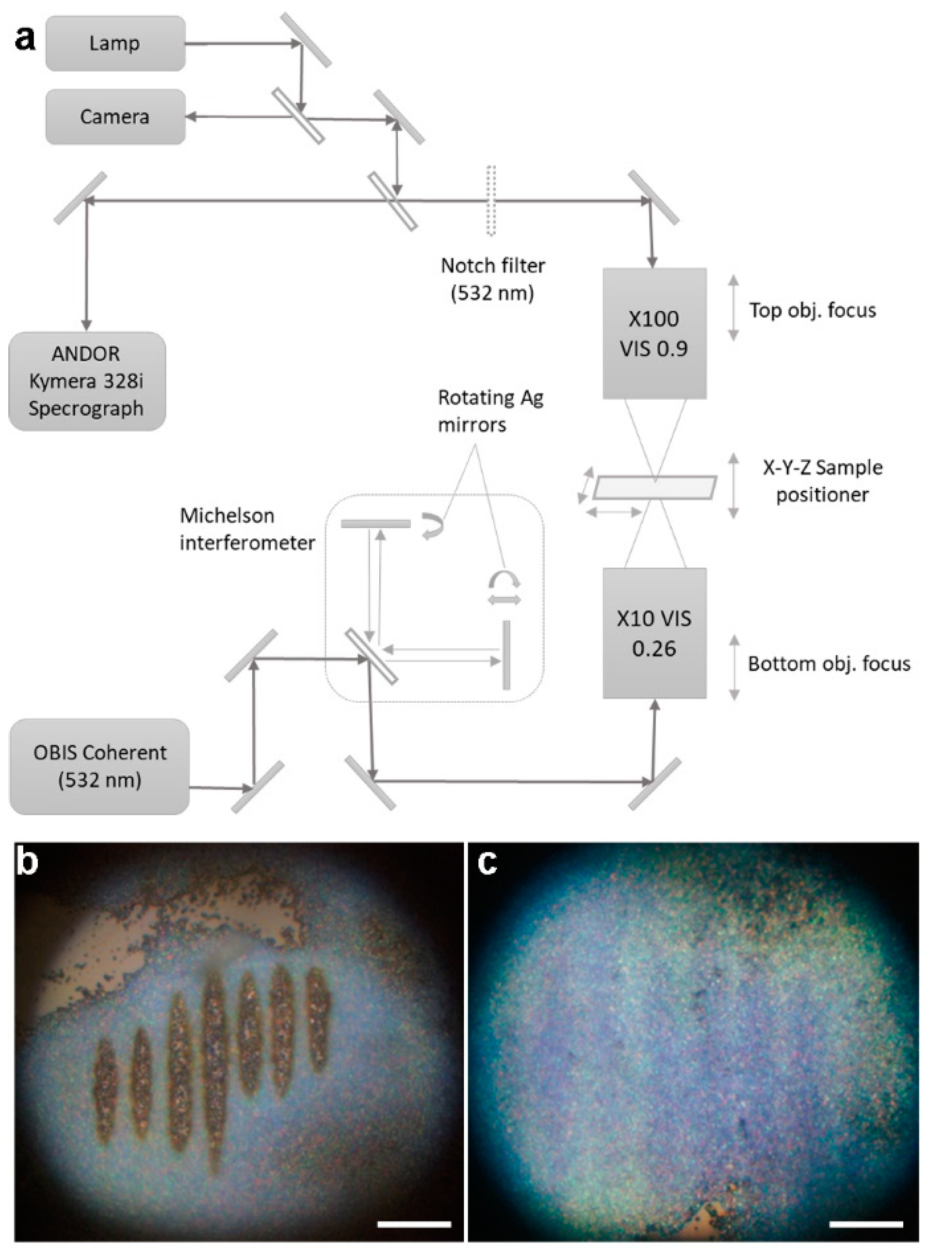
In the second step, an interference setup (Figure 2a) based on the ordinary Michelson interferometer and the OBIS Coherent (532 nm, 4 nm full width half maxima, 110 mW integral power) diode laser source was established. The pair of Ag mirrors on the shoulders of the interferometer include the angle adjustment, while one of them was mounted on the x-axis stage in order to regulate the distance. The interference pattern was focused on the backward plane of the film via an objective (Mytutoyo (Paris, France) Plan APO, 10×VIS, NA = 0.28). An optical image of the interference pattern on the MOF film was obtained from the front side of the film via an objective (Mitutoyo Plan APO, 50× VIS, NA = 0.55) and a CCD camera. The reflected (and Raman scattered) optical signal from the film was also collected by an objective (Mitutoyo Plan APO, 50× VIS, NA = 0.55) and then transferred to a confocal spectrometer. The obtained optical signal was additionally filtered by a 532 nm notch filter to prevent laser radiation.
Utilizing the interference scheme, we realized two modes of the film response: reversible (Figure 2c) and irreversible ones (Figure 2b). The former occurs for 1 s, with a laser intensity of tens of µW cm−2 (see below), due to laser-induced heating followed by the release of water molecules, as we described recently [26]. This process is characterized by a change in the compound refractive index and absorption coefficient [32], and also requires relatively low laser intensities to be initiated. What is important is that the reversible interference patterning does not have an effect on the inner structure of the MOF; hence, the thin film returns to its initial state after turning off the laser. In contrast, the latter mode (the irreversible one, occurring for 3–5 s at mW cm−2 laser intensity) is related to the thermal decomposition of HKUST-1 with the release of copper encapsulated in amorphous carbon [11,12,13,24,33]. Finally, both of these regimes could be realized on the same sample through the variation of the laser intensity (see below).
To estimate the period of the interference, Λ = (λ·l)/d, of the laser radiation, with a wavelength of λ = 532 nm focused on the film via a 10× objective, we measured the distances between the beam splitter and the film, l = 0.51 m, and two imaginary sources, d, on the scheme in Figure 2a (two laser beams passing through the beam splitter). Due to an ability to vary the angles of mirrors (Figure 2a) and a 10× magnification, we achieved d = 0.2–5 mm. Therefore, Λ equals approx. 5–136 µm, which is in good agreement with the optical images on Figure 2.
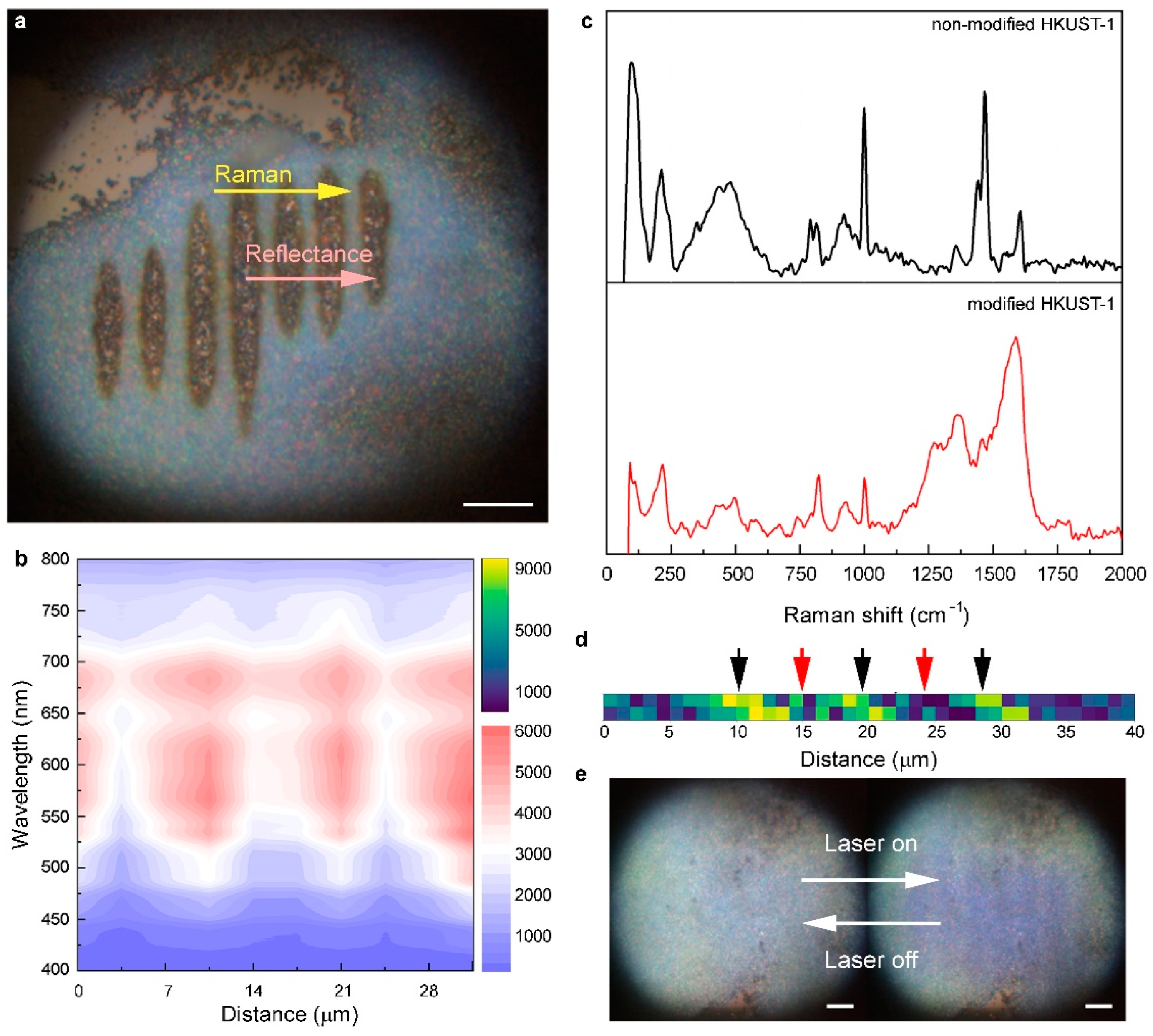
Since the irreversible mode changes the chemical structure of the initial MOF (Figure 3a), we performed Raman characterization using a self-made confocal optical setup based on the HORIBA LabRam spectrometer (Tokyo, Japan), with a water-cooling charge-coupled device (CCD, Andor DU 420A-OE 325), a 600 g mm−1 diffraction grating, and a high-aperture objective (Mitytoyo Plan Apo, 100× VIS, NA = 0.9) moving over the surface with a Thorlabs piezo-stage [34]. The Raman scattering signal was measured at 632.8 nm He–Ne continuous laser radiation excitation in reflection mode. Using this system, we mapped the coordination-bond breaking (the vibrations of Cu-O of the [Cu2C4O8] cage centered at 180–290 cm−1) [35] across the line shown in Figure 3a. As one can see (Figure 3c), the lower intensity of the coordination bonds and the newly appeared peaks of carbon (1320 and 1590 cm−1) correspond to the thermally decomposed areas with complete amorphization. The retained bonds highlighted with the black arrow in Figure 3d correspond to the non-modified area (i.e., an area of negative interference). We also checked the reflection spectra (via Andor Kymera 328i, iDus CCD detector, Oxford, UK) from the interference patterns: as in the case of the Raman mapping, Figure 3b illustrates that the irreversibly modified areas demonstrate relatively low reflectance as compared with the initial film. Despite the fact that the irreversible laser patterning of MOFs leads to the appearance of metal conglomerates [13], which should increase the surface reflection, the decline in reflection can be associated with another feature of laser exposure, i.e., the removal of material. We then analyzed this aspect using atomic force microscopy (AFM, SmartSPM 1000, Aist-NT microscope, Moscow, Russia). The AFM scans were performed at ambient conditions using HQ:NSC16 series cantilevers (HARD/AL BS and AL BS types by MikroMasch AFM probes/Innovative Solutions Bulgaria Ltd., Sofia, Bulgaria), with a force constant of around 45 N m−1 and a resonance frequency of 190 kHz.
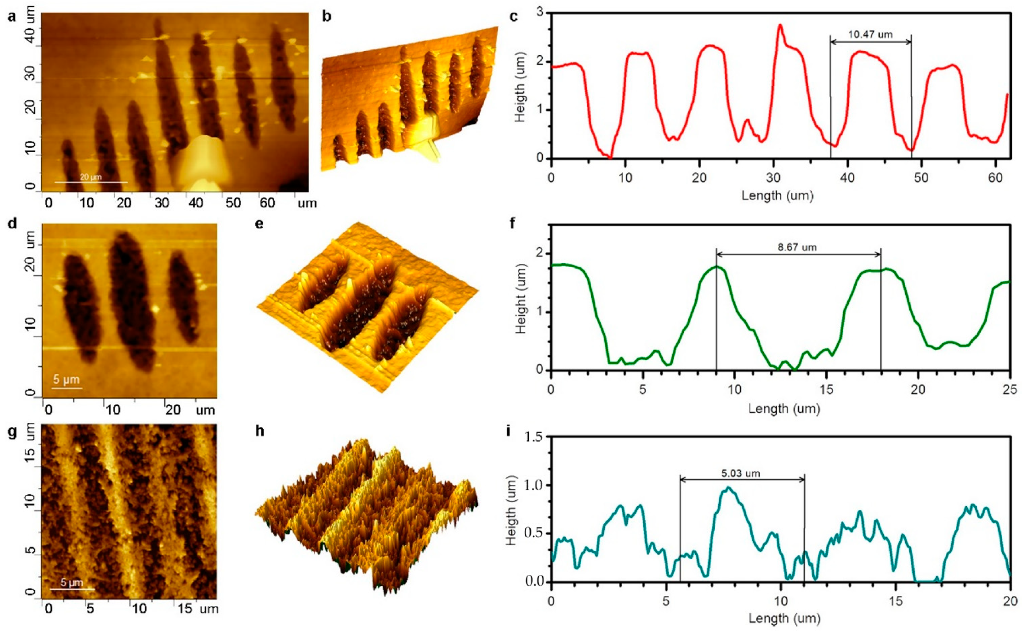
Figure 4 demonstrates three patterns (stripes) scanned by AFM in order to investigate the relationship between the laser interference periods and the changes in the surface roughness. As one can see, the patterned areas are characterized by the cavities inside the film (Figure 4b,e,h). Moreover, the roughness of the surface after the patterning strongly depends on the interference period: reducing the distance between the interference maxima from 10.5 µm (Figure 4a–c) to 8.7 µm (Figure 4d–f) and 5 µm (Figure 4g–i) increases the inhomogeneity of the surface by several tens of times. Based on these results, we can also estimate the laser intensities required for the reversible and irreversible modes. For a fixed period of the laser interference (8.7 µm), we estimated the area of the irradiated film in the reversible and irreversible modes (3600 and 180 µm2, respectively), which then makes it possible to estimate the laser intensities at a known laser power of 40 mW. We see that there is no patterning at a laser intensity less than 0.01 mW µm−2; then, the reversible pattern starts, and finally, at 0.22 mW µm−2, one can observe the irreversible patterning. These results confirm that irreversible laser patterning required 20 times more intensity as compared to the irreversible one.
Finally, the reversible mode presented on Figure 3e was realized due to the reversible process of water desorption [26], which accordingly causes a change in the color (contrast) of the HKUST film in the region of the laser interference maxima. This color-changing process is fast enough [26] and does not destroy the structure that it is possible to reversibly draw the stripes on the film surface more than 100 times at ambient conditions.

3. Conclusions

We have reported on MOF thin film patterning by laser interference in the reversible and irreversible modes. The utilization of the HKUST-1 thin film on a fused glass and a coherent 532 nm laser light with a varied intensity allowed us to draw the stripes in real time, with a period of up to 5 µm. The interference patterning in the irreversible mode was achieved with a threshold MOF decomposition using a highly intense laser light (0.22 mW µm−2), followed by the removal of its components from the modification area. In this study, the reversible one was demonstrated due to the change in the MOF color initiated by the laser-induced (0.01 mW µm−2) desorption of water molecules. A series of measurements via Raman and reflectance spectroscopy as well as atomic force microscopy allowed us to characterize the morphology of the resulting patterns. It was revealed that reducing the period of the irreversible pattern from 10.5 to a record of 5 µm yields a 10-fold increase in the surface roughness of the pattern; in contrast, the surface of the reversible pattern remains unmodified. The experimental results obtained confirm the unique possibility of utilizing MOFs as photosensitive films for the creation of desired patterns for various application scopes, including “smart” materials and responsive hybrid structures for sensing [36,37].

Author Contributions

V.A.M. conceived the research. S.R. synthesized the MOF thin films. Y.K. and S.B. performed the confocal Raman and reflection spectroscopy measurements. N.Z., E.G. and M.S. performed the reversible and irreversible laser interference patterning. N.Z. performed the PXRD analysis. A.E. performed the AFM analysis. N.Z., V.D. and V.A.M. contributed to the data analysis. All authors contributed to the writing of the manuscript. All authors have read and agreed to the published version of the manuscript.

Funding

The study is funded by RPMA grant of School of Physics and Engineering of ITMO University.

Institutional Review Board Statement

Not applicable.

Informed Consent Statement

Not applicable.

Data Availability Statement

Not applicable.

Conflicts of Interest

The authors declare no conflict of interests.

References

  1. Zhou, H.-C.; Long, J.R. Introduction to Metal–Organic Frameworks. Chem. Rev. 2012, 112, 673–674. [Google Scholar] [CrossRef] [PubMed]
  2. Furukawa, H.; Cordova, W.E. The Chemistry and Applications of Metal-Organic Frameworks. Science 2013, 341, 6149. [Google Scholar] [CrossRef] [PubMed] [Green Version]
  3. Xie, L.S.; Skorupskii, G. Electrically Conductive Metal–Organic Frameworks. Chem. Rev. 2020, 120, 8536–8580. [Google Scholar] [CrossRef] [PubMed] [Green Version]
  4. Kulachenkov, N.K.; Haar, Q. MOF-Based Sustainable Memory Devices. Adv. Funct. Mater. 2020, 32, 2107949. [Google Scholar] [CrossRef]
  5. Lv, Y.; Xiong, Z. Pure Metal–Organic Framework Microlasers with Controlled Cavity Shapes. Nano Lett. 2020, 20, 2020–2025. [Google Scholar] [CrossRef]
  6. Mingabudinova, L.R.; Vinogradov, V.V. Metal–organic frameworks as competitive materials for non-linear optics. Chem. Soc. Rev. 2016, 45, 5408–5431. [Google Scholar] [CrossRef] [Green Version]
  7. Danowski, W.; van Leeuwen, T. Unidirectional rotary motion in a metal–organic framework. Nat. Nanotechnol. 2019, 14, 488–494. [Google Scholar] [CrossRef]
  8. Ribeiro, E.L.; Davis, E.M. MOF-derived PtCo/Co3O4 nanocomposites in carbonaceous matrices as high-performance ORR electrocatalysts synthesized via laser ablation techniques. Catal. Sci. Technol. 2021, 11, 3002–3013. [Google Scholar] [CrossRef]
  9. Guo, S.; Zhao, Y.; Yuan, H.; Wang, C.; Jiang, H.; Cheng, G.J. Ultrafast Laser Manufacture of Stable, Efficient Ultrafine Noble Metal Catalysts Mediated with MOF Derived High Density Defective Metal Oxides. Small 2020, 16, 2000749. [Google Scholar] [CrossRef]
  10. Wang, K.-Y.; Feng, L. Rapid Generation of Hierarchically Porous Metal–Organic Frameworks through Laser Photolysis. Angew. Chem. Int. Ed. 2020, 59, 11349–11354. [Google Scholar] [CrossRef]
  11. Jiang, H.; Tong, L.; Liu, H.; Xu, J.; Jin, S.; Wang, C.; Hu, X.; Ye, L.; Deng, H.; Cheng, G.J. Graphene-Metal-Metastructure Monolith via Laser Shock-Induced Thermochemical Stitching of MOF Crystals. Matter 2020, 2, 1535–1549. [Google Scholar] [CrossRef] [Green Version]
  12. Ruiqian, M.; Haoqing, J. Multivariate MOFs for Laser Writing of Alloy Nanoparticle Patterns. Chem. Commun. 2020, 56, 2715–2718. [Google Scholar]
  13. Haoqing, J.; Shengyu, J. Nanoscale Laser Metallurgy and Patterning in Air Using MOFs. J. Am. Chem. Soc. 2019, 141, 5481–5489. [Google Scholar]
  14. Nakata, Y.; Osawa, K. Utilization of the high spatial-frequency component in adaptive beam shaping by using a virtual diagonal phase grating. Sci. Rep. 2019, 9, 4640. [Google Scholar] [CrossRef]
  15. Müller, D.W.; Fox, T. Applying Ultrashort Pulsed Direct Laser Interference Patterning for Functional Surfaces. Sci. Rep. 2020, 10, 3647. [Google Scholar] [CrossRef] [PubMed] [Green Version]
  16. Mulko, L.; Soldera, M. Structuring and functionalization of non-metallic materials using direct laser interference patterning: A review. Nanophotonics 2022, 11, 203–240. [Google Scholar] [CrossRef]
  17. Zhang, Y.; Su, Y.; Zhao, Y.; Wang, Z.; Wang, C. Two-Photon 3D Printing in Metal–Organic Framework Single Crystals. Small 2022, 18, 2200514. [Google Scholar] [CrossRef]
  18. Yu, J.; Cui, Y.; Wu, C.D.; Yang, Y.; Chen, B.; Qian, G. Two-Photon Responsive Metal–Organic Framework. J. Am. Chem. Soc. 2015, 137, 4026–4029. [Google Scholar] [CrossRef]
  19. Ameloot, R.; Roeffaers, M.B.J.; De Cremer, G.; Vermoortele, F.; Hofkens, J.; Sels, B.F.; De Vos, D.E. Metal–Organic Framework Single Crystals as Photoactive Matrices for the Generation of Metallic Microstructures. Adv. Mater. 2011, 23, 1788–1791. [Google Scholar] [CrossRef]
  20. Zhang, W.; Li, R.; Zheng, H.; Bao, J.; Tang, Y.; Zhou, K. Laser-Assisted Printing of Electrodes Using Metal–Organic Frameworks for Micro-Supercapacitors. Adv. Funct. Mater. 2021, 31, 2009057. [Google Scholar] [CrossRef]
  21. Pečinka, L.; Peña-Méndez, E.M.; Conde-González, J.E.; Havel, J. Laser ablation synthesis of metal-doped gold clusters from composites of gold nanoparticles with metal organic frameworks. Sci. Rep. 2021, 11, 4656. [Google Scholar] [CrossRef] [PubMed]
  22. Wu, Y.; Huang, Z.; Jiang, H.; Wang, C.; Zhou, Y.; Shen, W.; Xu, H.; Deng, H. Facile Synthesis of Uniform Metal Carbide Nanoparticles from Metal–Organic Frameworks by Laser Metallurgy. ACS Appl. Mater. Interfaces 2019, 11, 44573–44581. [Google Scholar] [CrossRef] [PubMed]
  23. Lam, D.V.; Dung, D.T.; Kim, J.H.; Kim, H.; Lee, S.M. Laser-induced sulfurization of nickel-based metal-organic frameworks for highly stable phase-engineered energy materials. Chem. Eng. J. 2022, 437, 135237. [Google Scholar] [CrossRef]
  24. Tang, Y.J.; Zheng, H.; Wang, Y.; Zhang, W.; Zhou, K. Laser-Induced Annealing of Metal–Organic Frameworks on Conductive Substrates for Electrochemical Water Splitting. Adv. Funct. Mater. 2021, 31, 2102648. [Google Scholar] [CrossRef]
  25. Kulachenkov, N.K.; Bruyere, S. Ultrafast Melting of Metal–Organic Frameworks for Advanced Nanophotonics. Adv. Funct. Mater. 2020, 30, 1908292. [Google Scholar] [CrossRef]
  26. Kulachenkov, N.K.; Sun, D. Photochromic Free MOF-Based Near-Infrared Optical Switch. Angew. Chem. Int. Ed. 2020, 59, 15522–15526. [Google Scholar] [CrossRef]
  27. Chui, S.S.-Y.; Lo, S.M.-F. A Chemically Functionalizable Nanoporous Material [Cu3(TMA)2(H2O)3]n. Science 1999, 283, 1148–1150. [Google Scholar] [CrossRef]
  28. Xu, S.; Chansai, S.; Stere, C.; Inceesungvorn, B.; Goguet, A.; Wangkawong, K.; Taylor, S.F.R.; Al-Janabi, N.; Hardacre, C.; Martin, P.A.; et al. Sustaining metal–organic frameworks for water–gas shift catalysis by non-thermal plasma. Nat. Catal. 2019, 2, 142–148. [Google Scholar] [CrossRef] [Green Version]
  29. He, C.; Liu, L. Volatile Organic Compound Vapour Measurements Using a Localised Surface Plasmon Resonance Optical Fibre Sensor Decorated with a Metal-Organic Framework. Sensors 2021, 21, 1420. [Google Scholar] [CrossRef]
  30. Al-Janabi, N.; Hill, P.; Murciano, L.T.; Garforth, A.; Gorgojo, P.; Siperstein, F.; Fan, X. Mapping the Cu-BTC metal–organic framework (HKUST-1) stability envelope in the presence of water vapour for CO 2 adsorption from flue gases. Chem. Eng. J. 2015, 281, 669–677. [Google Scholar] [CrossRef] [Green Version]
  31. Qi, Y.; Lin, S. Increased proton conductivity of metal–organic framework micro-film prepared by a facile salt-free approach. J. Mater. Chem. A 2014, 2, 8849–8853. [Google Scholar] [CrossRef]
  32. Kenzhebayeva, Y.; Bachinin, S.; Solomonov, A.I.; Gilemkhanova, V.; Shipilovskikh, S.A.; Kulachenkov, N.; Fisenko, S.P.; Rybin, M.V.; Milichko, V.A. Light-Induced Color Switching of Single Metal–Organic Framework Nanocrystals. J. Phys. Chem. Lett. 2022, 13, 777–783. [Google Scholar] [CrossRef] [PubMed]
  33. Mezenov, Y.A.; Bruyere, S. Probing the dynamics of Cu nanoparticle growth inside metal-organic frameworks upon electron beam irradiation. Photonics Nanostruct.—Fundam. Appl. 2020, 41, 100832. [Google Scholar] [CrossRef]
  34. Vinogradov, V.V.; Drozdov, A.S. Composites based on heparin and MIL-101(Fe): The drug releasing depot for anticoagulant therapy and advanced medical nanofabrication. J. Mater. Chem. B 2018, 6, 2450–2459. [Google Scholar] [CrossRef]
  35. Prestipino, C.; Regli, L.; Vitillo, J.G.; Bonino, F.; Damin, A.; Lamberti, C.; Zecchina, A.; Solari, P.L.; Kongshaug, K.O.; Bordiga, S. Local Structure of Framework Cu(II) in HKUST-1 Metallorganic Framework: Spectroscopic Characterization upon Activation and Interaction with Adsorbates. Chem. Mater. 2006, 18, 1337–1346. [Google Scholar] [CrossRef]
  36. Koryakina, I.; Kuznetsova, D.S. Optically responsive delivery platforms: From the design considerations to biomedical applications. Nanophotonics 2020, 9, 39–74. [Google Scholar] [CrossRef]
  37. Yin, Y.; Rogers, J.A. Introduction: Smart Materials. Chem. Rev. 2022, 122, 4885–4886. [Google Scholar] [CrossRef]
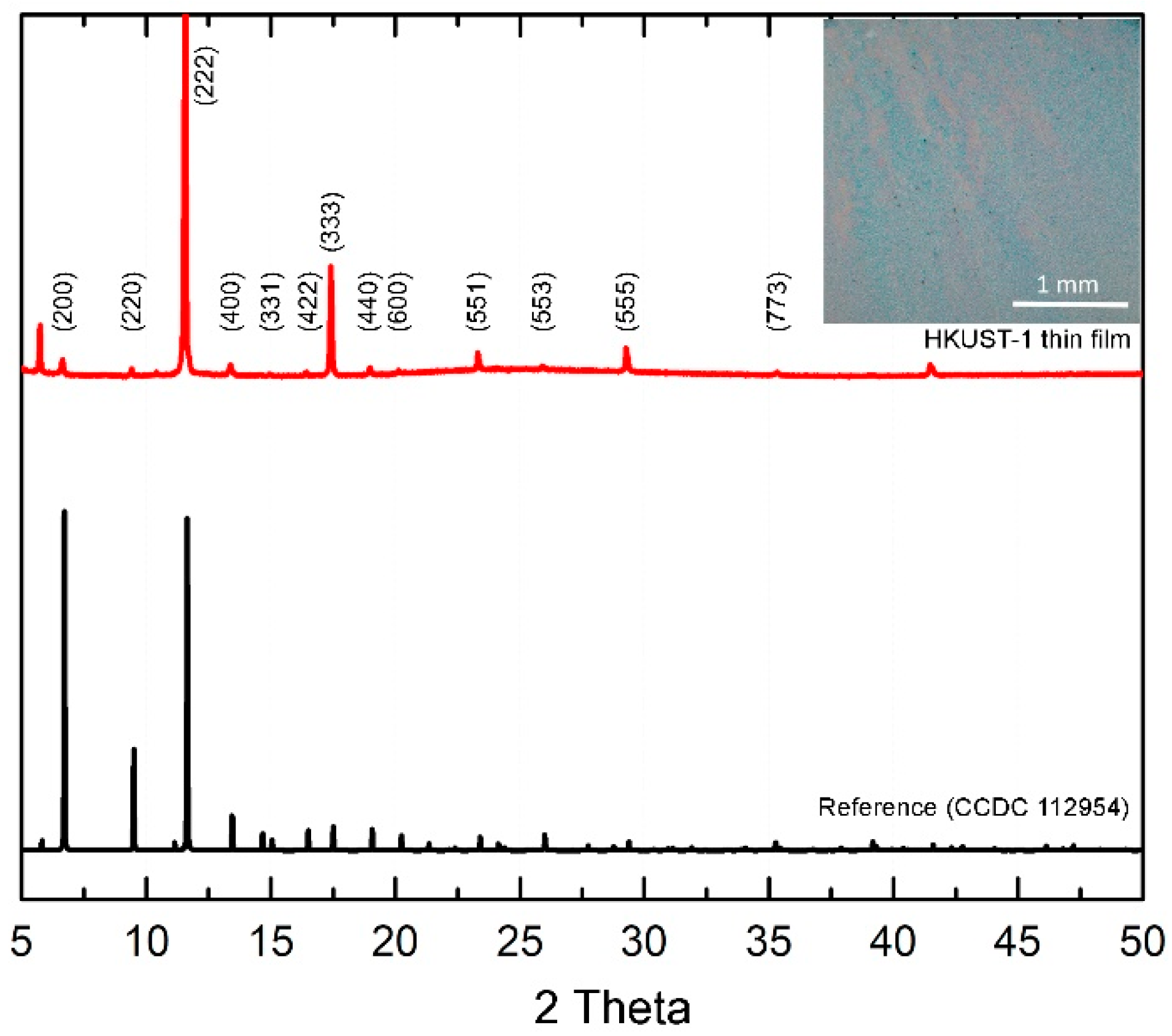
Figure 1. PXRD pattern of the synthesized HKUST-1 thin film and a reference compound (black curve, CCDC numb. 112954), with highlighted peaks from [31]. Inset: Optical image of the corresponding film. Scale bar, 1 mm.
Crystals 12 00846 g001
Figure 2. (a) Experimental setup based on the Michelson interferometer. (b,c) Optical images of irreversible and reversible laser patterning. Scale bar, 20 µm.
Crystals 12 00846 g002
Figure 3. (a) Optical image of the irreversible pattern, analyzed by (b) optical reflection (pink arrow) and (c,d) Raman (yellow arrow) mapping. Scale bar for (a), 20 µm. (c) The laser interference minima and maxima corresponding to the non-modified area (black curve and black arrows in (d)) and the modified area (red curve, red arrows in (d)) of the HKUST-1 thin film. (d) Raman mapping of coordination-bonds (the vibrations of Cu-O of the [Cu2C4O8] cage centered at 180–290 cm−1); black arrows indicate the bond retention, while the red ones correspond to bond breaking. (e) Optical images of the reversible mode. Scale bar, 20 µm.
Crystals 12 00846 g003
Figure 4. AFM analysis of three types of laser patterns corresponding to periods of (ac) 10.5, (df) 8.7, and (gi) 5 µm.
Crystals 12 00846 g004
Publisher’s Note: MDPI stays neutral with regard to jurisdictional claims in published maps and institutional affiliations.