Abstract
In this paper, multi-layer and multi-pass arc additive manufacturing experiments were carried out on the Q345 substrate using Y309L welding wire. Based on MSC. Marc software, a thermal-elastic-plastic finite element method was developed to numerically simulate the temperature field, stress field, and deformation during the additive manufacturing process. The effects of the substrate thickness and interpass temperature on the temperature field, stress field, and deformation were discussed. The results indicated that the deposition materials at different positions experienced different thermal cycles, which might lead to the non-uniform microstructure and mechanical properties within the workpiece. The interpass temperature and the thickness of the substrate influenced the residual stress distribution in the additive manufactured structure. A low interpass temperature and thin substrate was able to effectively reduce the tensile residual stress. The thick substrate resulted in a small angular deformation of the substrate during the additive manufacturing process.
1. Introduction
Wire Arc Additive Manufacturing (WAAM) is an additive manufacturing technology that uses an arc as a heat source to melt wires for directional deposition. Compared with other additive manufacturing technologies, WAAM technology has outstanding advantages, such as a high efficiency and low cost. During the manufacturing process, the wire metal cladding amount can reach 10 kg/h, and the material utilization rate is higher than 90% [1,2]. The prices of the wire and the equipment are significantly lower than in other additive methods, such as selective laser melting (SLM) [3] and electron beam additive manufacturing (EBAM) [4]. Large-sized or complex-structure parts can be manufactured using WAAM technology [5,6]. Meanwhile, WAAM products show a high performance and can even be comparable to traditional forgings under certain specific process conditions [7]. Thus, compared with traditional manufacturing methods, WAAM provides a new high-quality, high-efficiency, and low-cost method for the production of small-batch customized structural parts. At present, WAAM technology is widely used in practical industries. The Cranfield University in the UK has cooperated with the European Space Agency to manufacture large titanium alloy parts for aircraft using WAAM technology [8,9], and Bombardier Inc. has used WAAM technology to manufacture the rib of a wing [10]—which greatly improved the utilization rate of the materials and greatly reduced their production costs.
There are mainly two hindrances that have limited the potential application of additive manufacturing technologies, including WAAM [11], SLM [12], and EBAM [13] technologies. The first is the material defects in the products, such as gas inclusions, key-hole porosity, and lack-of-fusion defects. The second is the excessive residual stress and deformation caused by the rapid repeated heating and cooling process [14,15,16]. The existence of residual stress and deformation will not only greatly reduce the fatigue strength, crack resistance, and corrosion resistance of the products [17,18], but can also affect the subsequent machinability of the products—even directly leading to the failure of the manufacturing process. Carraturo et al. [19] developed an immersed boundary approach to evaluate residual stress. Their results indicated that the proposed immersed boundary approach can lead to a remarkable improvement in terms of computational time and memory usage when the mesh generation step is the main burden of a thermo-mechanical SLM process simulation. Adhitan et al. [20] investigated the stress evolution and re-melt volume fraction in the electron beam additive manufacturing process. In their study, the volume fraction of the re-melt material showed a non-linear and non-monotonic dependence on the electron beam size. Williams et al. [21] manufactured aircraft wings and special-shaped cones using WAAM technology. Their results indicated that high residual stress and deformation were the main problems with the process, which could be relieved by measures such as symmetrical alternating deposition, using a thick substrate, and performing simultaneous rolling. Li et al. [22] investigated the hybrid manufacturing process, combining WAAM with milling for the fabrication of stiffened panels. Their results indicated that the release of residual stress and deformation in the WAAM parts greatly reduced the cutting accuracy.
At present, the research on WAAM technology is mainly focused on the single-pass and multi-layer thin-walled components [23]. Only a few studies on multi-layer and multi-pass deposition have been reported. Martina et al. [24] manufactured a thick-walled structure using WAAM technology. The results showed that with the increase of the deposition height, it was difficult to ensure the structural formation of the component. After cooling to room temperature, there was large residual stress and deformation on both the deposition layer and the substrate. Belotti et al. [25] investigated the microstructural features of a thick-walled WAAM stainless steel part. Their research effectively improved the forming quality of the parts but lacked an in-depth analysis of residual stress and deformation. In the process of multi-layer and multi-pass deposition, the heat transfer characteristics in the deposition direction are more complex than in single-pass multi-layer deposition [1,23]—which will not only affect the stability of the molten pool shape in the subsequent deposition process but will also complicate the evolution of the microstructure, residual stress, and deformation within the component. However, the research on the above topics is inadequate and further quantitative investigations on residual stress and deformation during the WAAM process are still needed.
As basic research, this paper aimed to investigate the temperature field, stress field, and deformation during the WAAM process. In this paper, multi-layer and multi-pass arc additive manufacturing experiments were carried out on the Q345 substrate using Y309L welding wire, and the deformation of the substrate was measured. Meanwhile, based on MSC. Marc software, a thermal-elastic-plastic finite element method was developed to numerically simulate the temperature field, stress field, and deformation during the additive manufacturing process. The effects of the substrate thickness and interpass temperature on the temperature field, stress field, and deformation were discussed.
2. Experimental Procedures
In the additive manufacturing experiment, the substrate was Q345 low-alloy high-strength steel, and the deposition material was Y309L stainless steel wire with a diameter of 1.2 mm. Their chemical compositions are shown in Table 1. The substrate dimensions and weld pass arrangement are shown in Figure 1. The additive manufacturing experiments were carried out using robotic MIG (Metal-Inert Gas) welding machine TM1800 made by Panasonic (Tangshan, China). There were 4 layers and 10 passes in total. The welding current was 185 A, the welding voltage was 20 V, and the welding speed was 300 mm/min. The protective gas was pure Ar, and the gas flow was 18 L/min. After each welding pass, the workpiece was cooled to room temperature naturally in the air before the next welding pass. During the additive manufacturing process, no external restraint was applied and the angular deformation of the substrate was measured after each pass. After the additive manufacturing was completed, the deformation of the edge line L1 of the substrate (shown in Figure 1a) was recorded using the contour method. A schematic diagram of the substrate deformation measurement is shown in Figure 2. Due to the uneven surface of the additive manufactured workpiece, it is difficult to accurately measure the surface residual stress by the slicing method, pinhole method, or X-ray method. Therefore, the residual stress of the additive manufactured workpiece was not measured in this study. In future research, we plan to measure the residual stress of the additive manufactured products using the neutron diffraction method or the synchrotron radiation method.

Table 1.
Chemical compositions of the Q345 steel and Y309L wire (wt.%).
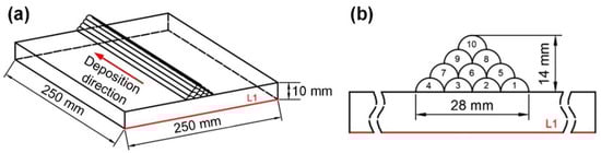
Figure 1.
(a) Substrate dimensions; (b) Weld pass arrangement.
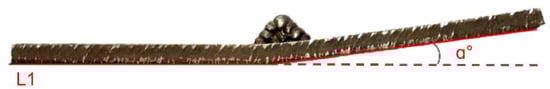
Figure 2.
Schematic diagram of the substrate deformation measurement.
3. Numerical Simulation
According to the geometric dimensions of the workpiece, the corresponding finite element model was established, as shown in Figure 3. It should be noted here that when simulating the deposition process of additive manufacturing, to simplify the modeling process and improve the calculation efficiency, this model did not accurately consider the cross-sectional shape of each weld bead and weld formation. In the established model, the center position and cross-sectional area of the weld were roughly equivalent to the actual weld bead. The height width of each weld pass were about 3.5 mm and 7.0 mm, respectively. To balance computational accuracy and computational efficiency, fine meshes were used in the weld pass and the heat-affected zone of the substrate, while relatively sparse meshes were used in the rest zone. The total number of elements in the model was 27,000 and the total number of nodes was 31,720.
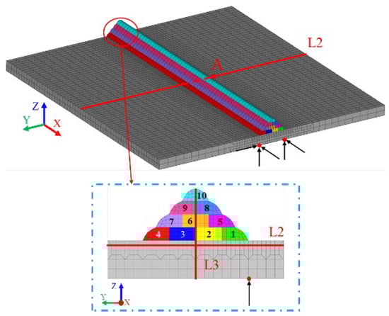
Figure 3.
Finite element model and boundary conditions.
A thermal-elastic-plastic finite element method was developed to numerically simulate the temperature field, stress field, and deformation during the additive manufacturing process, which was described in this section. The calculation process consisted of two parts, which were the thermal analysis and mechanical analysis. During the thermal analysis process, the temperature field was obtained. Then, the temperature data were introduced into the mechanical analysis as a thermal load to compute the stress and deformation. A heat source model was established. In this model, the actual additive manufacturing process was considered and the parameters related to heat transfer were set to improve the calculation accuracy of the temperature field. During the mechanical analysis, irrelevant factors were eliminated to shorten the calculation time.
The calculation software used in this study was MSC. MARC (2021, MSC software, Irvine, CA, USA). The element used in this model was the hexahedral 8-node element [26]. Since no external constraints were applied during the experiment, three-point constraints were applied in the finite element model to prevent the model from rigid movements during the calculation. The life–death element was used to simulate the deposition process of the metal. There were four calculation cases in this study, as shown in Table 2. Case A was consistent with the experiment. After each welding pass, the workpiece was cooled to room temperature before the next welding pass. The interpass temperature in Case A was 20 °C. In Case B, Case C, and Case D, the thickness of the substrate was varied to discuss its effects on the temperature field, stress field, and deformation of workpiece. To increase the efficiency of the additive manufacturing, the time between deposition layers was shortened to 33 s [15,27,28]. Thus, the interpass temperatures in Case B, Case C, and Case D were higher than 20 °C.
Table 2.
Simulation cases.
3.1. Heat Source Model and Thermal Analysis
In the additive manufacturing process, the heat transfer equation of the arc heat in the material is as shown in Equation (1).
where T is the temperature, λ is the thermal conductivity of materials, qv is the heat source power, ρ is the material density, c is the specific heat capacity of the materials, and t is the heat transfer time. x, y, and z are coordinates in the space coordinate system.
The dual ellipsoid heat source model proposed by Goldak et al. [29] was used to simulate the heat input in the additive manufacturing process. The heat flux densities of its front and back halves are described by Equations (2) and (3), respectively.
where qf and qr are the heat flux densities in the front and back half of the double ellipsoid heat source model, respectively. Q is the welding heat (Q = ηUI, U is the voltage, I is the current, and η is the thermal efficiency 0.8 [30,31,32]). af, ar, b, and c represent the shape parameters of the double ellipsoid, ff and fr represent the heat distribution function before and after the double ellipsoid; ff + fr = 2, and in this study, ff = 0.6, fr = 1.4 [33].
The convection and radiation were considered in this model to analyze the heat exchange between the workpiece and the external environment. The convective heat transfer is described by Newton’s law (Equation (4)), and the radiation heat transfer is described by the Stefan–Boltzmann law (Equation (5)).
where qc is the convection heat dissipation, hc = 15 × 10−6 W/(mm2·°C) is the convection exchange coefficient, qr is the radiation heat dissipation, ε = 0.8 is the radiation heat dissipation coefficient, σ is the Stefan–Boltzman constant, and T0 is the environment temperature (20 °C) [31,32,34,35].
The changes in the material properties with temperature were considered in the calculation process. The high-temperature thermophysical properties of the Q345 steel substrate and the Y309L wire [31,32] are shown in Figure 4.
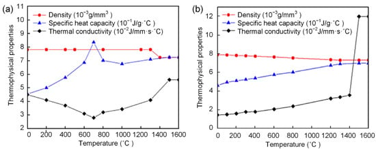
Figure 4.
Thermophysical properties of the (a) Q345 steel and (b) Y309L wire [31,32].
3.2. Mechanical Analysis
When calculating the stress field and deformation, the model used was the same as when calculating the temperature field. The calculation results of the temperature field were loaded into the finite element model as thermal loads for the elastic-plastic analysis. The total strain of the material during the calculation process could be expressed by the following formula:
where εtotal represents the total strain, εe is the elastic strain, εp is the plastic strain, εth is the thermal strain, εcr is the creep strain, and εph is the phase transformation strain.
The solid-state transformation of Q345 steel has little effect on residual stress and deformation [32]. The deposited material in this study was Y309L austenitic stainless steel, which had no solid-state transformation during the welding. Thus, the transformation strain was not considered in the calculation process. Since the high-temperature residence time in the arc additive manufacturing process was short and the creep phenomenon was not obvious, the creep strain was ignored. The total strain of the material during the additive manufacturing process could be expressed by the following formula:
The elastic strain calculation follows Hook’s law, and the plastic deformation adopts the Von–Mises criterion. The work hardening phenomenon of Q345 was not obvious [36]. However, Y309L is austenitic stainless steel with a significant tendency for work hardening. Thus, the work-hardening phenomenon of Q345 was ignored in the calculation process, and the isotropic criterion was used to describe the work-hardening effect of the Y309L [37]. At the same time, the annealing softening effect of the Y309L stainless steel was considered because the deposition layers underwent multiple thermal cycles. In this study, a step annealing model was used to describe the annealing softening effect. The annealing temperature was set to 1000 °C [38]. The high-temperature mechanical properties of the Q345 and the Y309L are shown in Figure 5.
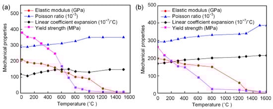
Figure 5.
Mechanical properties of the (a) Q345 steel and (b) Y309L wire.
4. Results and Discussion
4.1. Deformation
Figure 6 shows the calculated and experimental angular deformations of the substrate in Case A. The calculated results agreed well with the experimental measurements, which verified the reliability of the developed finite element method. When the additive manufacturing was finished, obvious asymmetric welding deformation occurred in the substrate. The final angular deformation of the substrate was about 8°. The angular deformation increment was significant when the first layer was deposited. Then, the angular deformation increments gradually decreased with increases in the deposition height.
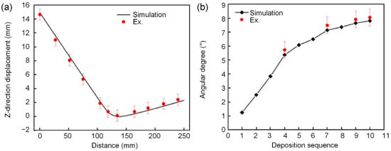
Figure 6.
Calculated and experimental results for the deformation of the substrate in Case A. (a) Z-direction displacement; (b) angular deformation.
4.2. Temperature Field
Figure 7 shows the temperature distributions in Case C when the heat source moved to the center of the 1st, 6th, and 10th weld pass. It can be seen from Figure 7 that as the additive manufacturing process proceeded, the high-temperature area of the substrate and the size of the molten pool increased accordingly. This phenomenon was mainly due to the heat-accumulation effect of the additive manufacturing process. During the additive manufacturing process, more and more heat accumulated in the workpiece, increasing the temperature of the substrate and the size of the molten pool.
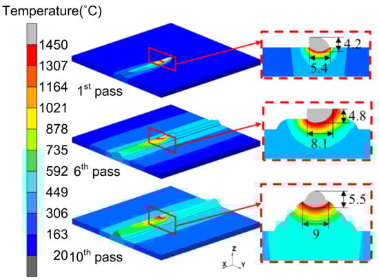
Figure 7.
Temperature fields.
Figure 8 illustrates the temperature histories of the deposition materials in the 1st, 6th, and 10th weld passes. Due to the heating effect of the subsequent weld passes, these thermal cures showed different characteristics. For the deposition material in the 1st weld pass, there were a total of ten temperature peaks in its thermal curve. The first temperature peak (1857 °C) was due to the deposition process of the 1st weld pass. The other nine temperature peaks were due to the heating effect of subsequent weld passes. The closer the subsequent weld pass was to the 1st weld pass, the more significant heating effect on the deposition materials in the 1st weld pass it had, and the higher the corresponding temperature peak was. Since the 5th weld pass was near the 1st weld pass, it had a significant heating effect on the deposition materials in the 1st weld pass. The corresponding peak temperature exceeded the melting point of the material, resulting in remelting of the deposition materials in the 1st weld pass. For the deposition materials in the 6th and 10th weld pass, their thermal curves were different from that of the 1st weld pass. Owing to the heat-accumulation effect of the additive manufacturing process, the maximum peak temperatures of the 1st, 6th, and 10th weld passes gradually increased, reaching 1857 °C, 2056 °C, and 2180 °C, respectively. In the thermal curve of the deposition materials in the 6th pass, the corresponding peak temperatures of the 7th, 8th, and 9th weld passes were close to the melting point of the deposition material. It can be seen from the above analysis that the deposition materials at different positions experienced different thermal cycles, which may have led to the non-uniform microstructure and mechanical properties within the workpiece.
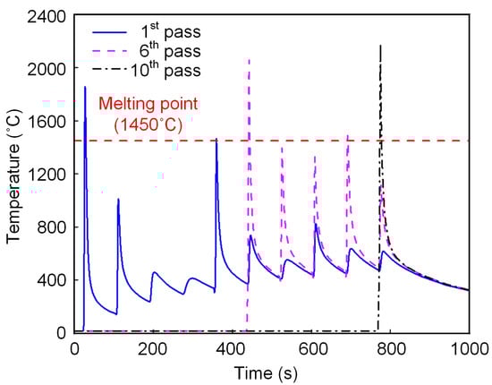
Figure 8.
Thermal cycle curves in different passes.
Figure 9 shows the temperature cycling curves at point A when the substrate thicknesses were 5 mm, 10 mm, and 20 mm, respectively. Point A was located in the middle of the substrate, 5 mm from the edge of the 1st weld pass. It could be seen from the figure that as the additive manufacturing process proceeded, the interpass temperature increased. With the same welding parameters, a thick substrate can effectively reduce the interpass temperature. When the thickness of the substrate increased from 5 mm to 20 mm, the maximum temperature at point A decreased from 642 °C to 304 °C. This was because, during the additive manufacturing process, the thermal conduction and heat dissipation of the deposition heat through the substrate was much faster than the convection and radiation heat dissipation on the surface of the deposition layer. The thicker the substrate was, the more conducive to rapid heat dissipation it was.
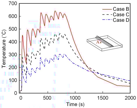
Figure 9.
Thermal cycle curves in Position A.
4.3. Residual Stress Field
Figure 10 shows the residual stress distribution on the central sections of the models in four cases. High residual stress formed inside the deposition layers as well as in the middle of the substrate. The longitudinal and transverse residual stress peaks inside the deposition layers exceeded the room-temperature yield strength of Y309L. This was because Y309L had a high tendency for work hardening. During the additive manufacturing process, large plastic deformation formed in the deposition layers, increasing the yield strength of the material. In addition, the materials at certain locations inside the deposited layers were in a state of triaxial stress, which also contributed to the formation of high residual stresses.
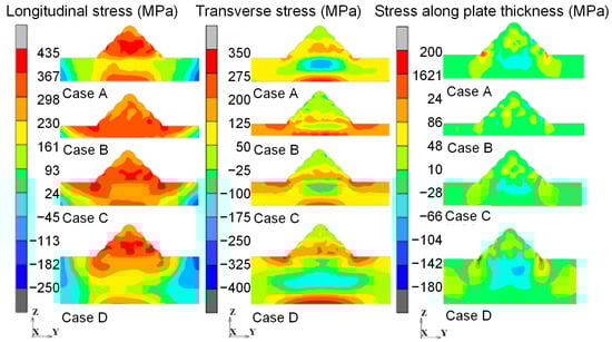
Figure 10.
Residual stress distribution of the model central section in the four cases.
In Case B, Case C, and Case D, high longitudinal tensile residual stress formed inside the deposition layers and in the middle of the substrates. With increases in the substrate thickness, the longitudinal high tensile stress area in the deposition layers gradually increased, while the longitudinal high tensile stress area in the middle of the substrate gradually decreased. The transverse tensile residual stress was mainly concentrated in the vicinity of the upper and lower surfaces of the substrate, and the balanced transverse compressive residual stress was distributed in the middle of the substrate and the top of the deposition layers. At the weld toes, there were high tensile residual stresses in three directions. With the increase of the substrate thickness, the area of high tensile residual stress increased gradually. The triaxial residual stresses limited the further plastic deformation of the materials at the weld toes and increased the risk of brittle fractures. Comparing Case A and Case C, it could be found that the longitudinal high tensile stress area in Case C was significantly larger than that in Case A, while the transverse compressive residual stress area was smaller than that in Case A. Thus, a low interpass temperature could effectively reduce the tensile residual stress during the additive manufacturing process.
Figure 11 shows the distribution of longitudinal and transverse residual stress on the central section of the substrate along line L2, which was 2 mm away from the upper surface of the substrate. The longitudinal residual stress was high tensile stress in the middle of the substrate and was compressive stress on both sides of the substrate. In Case B, Case C, and Case D, the longitudinal tensile stress peaks were located below the weld toes. With the increase in substrate thickness, the longitudinal tensile stress peaks (391 MPa, 383 MPa, 337 MPa) decreased gradually. The transverse tensile stress peaks appeared below the weld toes. In the area between the two weld toes, the transverse tensile stress decreased rapidly and turned into compressive stress. With the increase in substrate thickness, the peak value of the transverse tensile stress changed little, but the area of the high tensile stress gradually decreased. Case A and Case C were compared to illustrate the effect of the interpass temperature on the stress distribution. It could be seen that low interpass temperatures reduced the high tensile stress region and lowered the tensile stress peak but increased the transverse compressive stress peak in the middle of the substrate. Therefore, if only reductions in tensile residual stress are considered, a low interpass temperature is recommended for additive manufacturing.
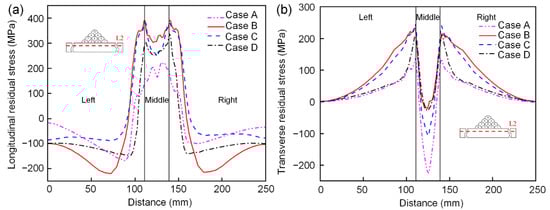
Figure 11.
Residual stress distribution along line L2. (a) Longitudinal residual stress; (b) Transverse residual stress.
Figure 12 shows the distribution of residual stress on L3. There was a large stress gradient near the Y309L/Q345 interface, which was mainly due to the thermal stress generated by the difference in the linear expansion coefficients of the two materials. In terms of the material parameters, the linear expansion coefficient of Y309L is about 40% larger than that of Q345. Inside the deposition layers, the longitudinal and transverse residual stresses at the bottom were significantly higher than those at the top. The thickness of the substrate determined the structural constraint of the workpiece—thus influencing the residual stress distributions. As the thickness of the substrate increased, the structural constraint of the workpiece increased correspondingly. As a result, both the high residual stress region and the residual stress peaks inside the deposition layers increased. If only reductions in the tensile residual stress in the deposition layers are considered, a thin substrate is recommended.
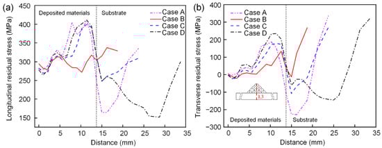
Figure 12.
Residual stress distribution along line L3. (a) Longitudinal residual stress; (b) Transverse residual stress.
4.4. Deformation Evolution
Figure 13 shows the angular deformation evolution of the substrates in four cases. The thickness of the substrate influenced the variation trend and final value of the angular deformation. Comparing Case B (5 mm) and Case C (10 mm), although their final angular deformations were close, the evolution processes of their angular deformations were different. In Case B, the angular deformation increment was almost invariable during the first three layers, but increased remarkably in the 4th layer. In Case C, the angular deformation increment was large in the 1st layer, then decreased gradually in the subsequent three layers. Case D (20 mm) had the smallest angular deformation. Only slight angular deformation of the substrate occurred when the first layer was deposited. In the subsequent deposition process, the substrate was free from further angular deformation. It was worth noting that although Case A and Case C had different interpass temperatures, their evolution processes for the angular deformation were almost the same.
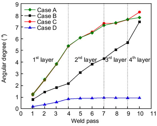
Figure 13.
Angular deformation revolution of the substrate in four cases.
In the additive manufacturing process, the angular deformation of the substrate was due to the uneven transverse shrinkage in its thickness direction. The driving force was the temperature gradient in the thickness direction of the substrate, and the resistance was the bending stiffness of the substrate. In Case B, the substrate was thin (5 mm). When depositing the first layer, the driving force of the angular deformation was small due to the small temperature gradient in the thickness direction of the substrate. With the increase in deposition height, the temperature gradient increased—thus increasing the driving force of the angular deformation correspondingly. However, the bending stiffness of the substrate also increased. Therefore, the angular deformation increments of the 2nd and 3rd layers were almost unchanged. Figure 3 shows that compared with previous layers, the 4th layer has a small contact area with the 3rd layer. During the deposition of the 4th layer, the arc heat could not be conducted into the previous layers rapidly and accumulated in the 4th layer. Thus, the temperature gradient in the workpiece increased, leading to the large angular deformation increment in this layer. In Case C, the substrate was thicker than that in Case B, which led to their different angular deformation evolutions of the substrate. When depositing the 1st layer, the angular deformation increment was large due to the large temperature gradient in the thickness direction of the substrate. As the additive manufacturing process proceeded, the bending stiffness of the workpiece gradually increased. The resistance of the angular deformation increased gradually, leading to a smaller increment in angular deformation in the subsequent deposition process. In Case D, since the substrate was thick (20 mm), its high bending stiffness limited the angular deformation of the substrate and only a small degree of angular deformation occurred after the additive manufacturing. Therefore, if only the control of the angular deformation of the substrate is considered, a thick substrate is recommended.
5. Conclusions
- During the additive manufacturing process, the deposition materials at different positions experienced different thermal cycles, which might have led to the non-uniform microstructure and mechanical properties within the workpiece. Increasing the thickness of the substrate could effectively slow down the increase in the interpass temperature.
- The interpass temperature and the thickness of the substrate influenced the residual stress distribution in the additive manufactured structure. A low interpass temperature and thin substrate could effectively reduce the tensile residual stress. The weld toes suffered from tensile residual stresses in three directions. A thick substrate increased the tensile residual stresses and the risk of brittle fractures in the weld toes.
- The calculated results for the angular deformation of the substrate agreed well with the experimental results, verifying the reliability of the finite element method developed. Increasing the thickness of the substrate could effectively reduce the deformation of the substrate during the additive manufacturing process.
Author Contributions
Conceptualization, G.F., H.W. and D.D.; methodology, G.F., H.W., Y.W. and D.D.; software, H.W.; validation, G.F. and H.W.; formal analysis, G.F. and H.W.; investigation, G.F. and H.W.; resources, G.F. and D.D.; data curation, G.F. and H.W.; writing—original draft preparation, G.F. and H.W.; writing—review and editing, G.F.; visualization, G.F., H.W. and J.Z.; supervision, G.F. and D.D.; project administration, G.F. and D.D.; funding acquisition, G.F. and D.D. All authors have read and agreed to the published version of the manuscript.
Funding
This research was funded by the National Natural Science Foundation of China, grant number 51875063 and 51905055; by the Natural Science Foundation of Chongqing, grant number cstc2020jcyj-msxmX0115; by the Fundamental Research Funds for the Central Universities Project, grant number 2020CDJLHZZ-086 and 2022CDJXY-010; and by the State Key Laboratory of Advanced Welding & Joining, grant number AWJ-21M08.
Institutional Review Board Statement
Not applicable.
Informed Consent Statement
Not applicable.
Data Availability Statement
Not applicable.
Conflicts of Interest
The authors declare no conflict of interest.
References
- Cunningham, C.R.; Flynn, J.M.; Shokrani, A.; Dhokia, V.; Newman, S.T. Invited review article: Strategies and processes for high quality wire arc additive manufacturing. Addit. Manuf. 2018, 22, 672–686. [Google Scholar] [CrossRef]
- Jin, W.; Zhang, C.; Jin, S.; Tian, Y.; Wellmann, D.; Liu, W. Wire Arc Additive Manufacturing of Stainless Steels: A Review. Appl. Sci. 2020, 10, 1563. [Google Scholar] [CrossRef] [Green Version]
- Zhu, Z.; Huang, H.; Min, S.; Hou, J.; Ji, W. Characterization of microstructure and hardening of SLM nickel-based alloy irradiated by He ions. J. Nucl. Mater. 2022, 566, 153794. [Google Scholar] [CrossRef]
- Pu, Z.; Du, D.; Wang, K.; Liu, G.; Zhang, D.; Liang, Z.; Xi, R.; Wang, X.; Chang, B. Evolution of transformation behavior and tensile functional properties with process parameters for electron beam wire-feed additive manufactured NiTi shape memory alloys. Mater. Sci. Eng. A 2022, 840, 142977. [Google Scholar] [CrossRef]
- Ermakova, A.; Mehmanparast, A.; Ganguly, S. A review of present status and challenges of using additive manufacturing technology for offshore wind applications. Procedia Struct. Integr. 2019, 17, 29–36. [Google Scholar] [CrossRef]
- Ren, H.J.; Zhou, G.N.; Cong, B.Q.; Ma, H.J.; Dong, W.Q. Development and application of Metal additive manufacturing in Aerospace field. Aeronaut. Manuf. Technol. 2020, 63, 72–77. [Google Scholar]
- Debroy, T.; Wei, H.L.; Zuback, J.S.; Mukherjee, T.; Elmer, J.W.; Milewski, J.O.; Beese, A.M.; Wilson-Heid, A.; De, A.; Zhang, W. Additive manufacturing of metallic components–Process, structure and properties. Prog. Mater. Sci. 2018, 92, 112–224. [Google Scholar] [CrossRef]
- Gu, J.; Ding, J.; Williams, S.W.; Gu, H.; Ma, P.; Zhai, Y. The effect of inter-layer cold working and post-deposition heat treatment on porosity in additively manufactured aluminum alloys. J. Mater. Res. Technol. 2016, 230, 26–34. [Google Scholar] [CrossRef]
- Martina, F.; Roy, M.J.; Szost, B.A.; Terzi, S.; Colegrove, P.A.; Williams, S.W.; Withers, P.J.; Meyer, J.; Hofmann, M. Residual stress of as-deposited and rolled wire + arc additive manufacturing Ti–6Al–4V components. Mater. Sci. Technol. 2016, 32, 1439–1448. [Google Scholar] [CrossRef] [Green Version]
- Lu, Z.; Tian, H.; Chen, S.; Li, F. Review on Precision Control Technologies of Additive Manufacturing Hybrid Subtractive Process. Acta Metall. Sin. 2020, 56, 83–98. [Google Scholar]
- Singh, S.; Sharma, S.K.; Rathod, D.W. A review on process planning strategies and challenges of WAAM. Mater. Today Proc. 2021, 47, 6564–6575. [Google Scholar] [CrossRef]
- Wei, W.; Xiao, J.C.; Wang, C.F.; Cheng, Q.; Guo, F.J.; He, Q.; Wang, M.S.; Jiang, S.Z.; Huang, C.X. Hierarchical microstructure and enhanced mechanical properties of SLM-fabricated GH5188 Co-superalloy. Mater. Sci. Eng. A 2022, 831, 142276. [Google Scholar] [CrossRef]
- Zykova, A.; Vorontsov, A.; Nikolaeva, A.; Chumaevskii, A.; Kalashnikov, K.; Gurianov, D.; Savchenko, N.; Nikonov, S.; Kolubaev, E. Structural design and performance evaluation of Ti6Al4V/5%Cu produced by electron-beam additive technology with simultaneous double-wire feeding. Mater. Lett. 2022, 312, 131586. [Google Scholar] [CrossRef]
- Somashekara, M.A.; Naveenkumar, M.; Kumar, A.; Viswanath, C.; Simhambhatla, S. Investigations into effect of weld-deposition pattern on residual stress evolution for metallic additive manufacturing. Int. J. Adv. Manuf. Technol. 2017, 90, 2009–2025. [Google Scholar] [CrossRef]
- Lee, Y.; Bandari, Y.; Nandwana, P.; Gibson, B.T.; Simunovic, S. Effect of Interlayer Cooling Time, Constraint and Tool Path Strategy on Deformation of Large Components Made by Laser Metal Deposition with Wire. Appl. Sci. 2019, 9, 5115. [Google Scholar] [CrossRef] [Green Version]
- Wang, L.; Xue, J.; Wang, Q. Correlation between arc mode, microstructure, and mechanical properties during wire arc additive manufacturing of 316L stainless steel. Mater. Sci. Eng. A 2019, 751, 183–190. [Google Scholar] [CrossRef]
- Ahsan, M.R.U.; Tanvir, A.N.M.; Seo, G.J.; Bates, B.; Hawkins, W.; Lee, C.; Liaw, P.K.; Noakes, M.; Nycz, A.; Kim, D.B. Heat-treatment effects on a bimetallic additively-manufactured structure (BAMS) of the low-carbon steel and austenitic-stainless steel. Addit. Manuf. 2020, 32, 101036. [Google Scholar] [CrossRef]
- Colegrove, P.A.; Coules, H.E.; Fairman, J.; Martina, F.; Kashoob, T.; Mamash, H.; Cozzolino, L.D. Microstructure and residual stress improvement in wire and arc additively manufactured parts through high-pressure rolling. J. Mater. Res. Technol. 2013, 213, 1782–1791. [Google Scholar] [CrossRef]
- Carraturo, M.; Kollmannsberger, S.; Reali, A.; Auricchio, F.; Rank, E. An immersed boundary approach for residual stress evaluation in selective laser melting processes. Addit. Manuf. 2021, 46, 102077. [Google Scholar] [CrossRef]
- Adhitan, R.K.; Raghavan, N. Transient thermo-mechanical modeling of stress evolution and re-melt volume fraction in electron beam additive manufacturing process. Procedia Manuf. 2017, 11, 571–583. [Google Scholar] [CrossRef]
- Williams, S.W.; Martina, F.; Addison, A.C.; Ding, J.; Colegrove, P. Wire + Arc Additive Manufacturing. Mater. Sci. Technol. 2016, 32, 641–647. [Google Scholar] [CrossRef] [Green Version]
- Li, F.; Chen, S.; Shi, J.; Tian, H.; Zhao, Y. Evaluation and Optimization of a Hybrid Manufacturing Process Combining Wire Arc Additive Manufacturing with Milling for the Fabrication of Stiffened Panels. Appl. Sci. 2017, 7, 1233. [Google Scholar] [CrossRef] [Green Version]
- Oyama, K.; Diplas, S.; M′Hamdi, M.; Gunnæs, A.E.; Azar, A.S. Heat source management in wire-arc additive manufacturing process for Al-Mg and Al-Si alloys. Addit. Manuf. 2019, 26, 180–192. [Google Scholar] [CrossRef]
- Martina, F.; Ding, J.; Williams, S.; Caballero, A.; Pardal, G.; Quintino, L. Tandem metal inert gas process for high productivity wire arc additive manufacturing in stainless steel. Addit. Manuf. 2019, 25, 545–550. [Google Scholar] [CrossRef] [Green Version]
- Palmeira Belotti, L.; Van Dommelen, J.A.W.; Geers, M.G.D.; Goulas, C.; Ya, W.; Hoefnagels, J.P.M. Microstructural characterisation of thick-walled wire arc additively manufactured stainless steel. J. Mater. Res. Technol. 2022, 299, 117373. [Google Scholar] [CrossRef]
- Dai, P.; Hu, X.; Lu, S.; Wang, Y.; Deng, D. Influence of Size Factor on Calculation Accuracy of Welding Residual Stress of Stainless Steel Pipeby 2D Axisymmetric Model. Acta Metall. Sin. 2020, 56, 83–98. [Google Scholar]
- Xiong, J.; Li, R.; Lei, Y.; Chen, H. Heat propagation of circular thin-walled parts fabricated in additive manufacturing using gas metal arc welding. J. Mater. Process. Technol. 2018, 251, 12–19. [Google Scholar] [CrossRef]
- Zhao, H.; Zhang, G.; Yin, Z.; Lin, W. A 3D dynamic analysis of thermal behavior during single-pass multi-layer weld-based rapid prototyping. J. Mater. Process. Technol. 2011, 211, 488–495. [Google Scholar] [CrossRef]
- Goldak, J.; Chakravarti, A.; Bibby, M. A new finite element model for welding heat sources. Metall. Trans. B 1984, 15, 299–305. [Google Scholar] [CrossRef]
- Li, X.; Hu, L.; Deng, D. Influence of contact behavior on welding distortion and residual stress in a thin-plate butt-welded joint performed by partial-length welding. Thin. Wall. Struct. 2022, 176, 109302. [Google Scholar] [CrossRef]
- Feng, G.; Wang, Y.; Luo, W.; Hu, L.; Deng, D. Comparison of welding residual stress and deformation induced by local vacuum electron beam welding and metal active gas arc welding in a stainless steel thick-plate joint. J. Mater. Res. Technol. 2021, 13, 1967–1979. [Google Scholar] [CrossRef]
- Wang, Y.; Feng, G.; Pu, X.; Deng, D. Influence of welding sequence on residual stress distribution and deformation in Q345 steel H-section butt-welded joint. J. Mater. Res. Technol. 2021, 13, 144–153. [Google Scholar] [CrossRef]
- Deng, D.; Murakawa, H. Numerical simulation of temperature field and residual stress in multi-pass welds in stainless steel pipe and comparison with experimental measurements. Comput. Mater. Sci. 2006, 37, 269–277. [Google Scholar] [CrossRef]
- Dai, P.; Li, S.; Wu, L.; Wang, Y.; Feng, G.; Deng, D. A new numerical model to predict welding-induced sensitization in SUS304 austenitic stainless steel joint. J. Mater. Res. Technol. 2022, 17, 234–243. [Google Scholar] [CrossRef]
- Hu, X.; Feng, G.; Wang, Y.; Zhang, C.; Deng, D. Influence of lumping passes on calculation accuracy and efficiency of welding residual stress of thick-plate butt joint in boiling water reactor. Eng. Struct. 2020, 222, 111136. [Google Scholar] [CrossRef]
- Deng, D.; Kiyoshima, S. Numerical simulation of welding temperature field, residual stress and deformation induced by electro slag welding. Comput. Mater. Sci. 2012, 62, 23–34. [Google Scholar] [CrossRef]
- Deng, D.; Kiyoshima, S. FEM analysis of residual stress distribution near weld start/end location in thick plates. Comput. Mater. Sci. 2011, 50, 2459–2469. [Google Scholar] [CrossRef]
- Deng, D.; Shoichi, K. Influenceof annealing temperature on calculation accuracy of welding residual stress in a SUS304 stainless steel joint. Acta Metall. Sin. 2014, 50, 626–632. [Google Scholar]
Publisher’s Note: MDPI stays neutral with regard to jurisdictional claims in published maps and institutional affiliations. |
© 2022 by the authors. Licensee MDPI, Basel, Switzerland. This article is an open access article distributed under the terms and conditions of the Creative Commons Attribution (CC BY) license (https://creativecommons.org/licenses/by/4.0/).