Article

Characteristics of a 2-2 Piezoelectric Composite Transducer Made by Magnetic Force Assembly

Department of Mechanical and System Engineering, Korea Military Academy, Seoul 01805, Korea
Crystals 2022, 12(5), 740; https://doi.org/10.3390/cryst12050740
Submission received: 17 April 2022 / Revised: 13 May 2022 / Accepted: 19 May 2022 / Published: 20 May 2022

Abstract

:
A wider operational bandwidth, a higher electromechanical coupling factor, and lower acoustic impedance are important requirements for ultrasound transducers for use across many applications. Conventional 2-2 piezoelectric composite transducers have been widely researched because of their wider bandwidth and higher sensitivity over their piezoelectric ceramic counterparts. In this paper, the fabrication of a novel 2-2 piezoelectric composite using magnetic force assembly is proposed to explore the potential of the transducer and to minimize mode coupling effect compared to 1–3 composites. To determine the desired transducer performance, such as the electromechanical coupling factor, the operational bandwidth, and the acoustic impedance, the design of a 2-2 composite should be considered using the mode-coupling theory and an effective medium model. The experimental results indicate that the electromechanical coupling factor and the −6 dB fractional bandwidth of the composite achieve values of 0.58 and 65.2%, respectively, which are comparable to those of traditional 1-3 piezoceramic/epoxy composites.

1. Introduction

Piezoelectric composite ultrasound transducers are preferred in many applications, such as underwater sonar, biomedical imaging, and nondestructive testing (NDT) applications, due to their wide operational bandwidth and high electromechanical coupling factor [1,2,3,4]. A broadband transducer can offer better imaging performance with a higher spatial resolution. Piezoelectric composites are composed of an active piezoelectric phase and a passive polymer matrix. They have a certain connection mode, volume ratio, and spatial geometric distribution. For piezoelectric composites, a piezoelectric material with strong piezoelectric characteristics such as lead zirconate titanate (PZT) or lead titanate (PT) is generally selected as the piezoelectric phase, and the polymer matrix is generally epoxy resin in order to lower acoustic impedance. Piezoelectric composites are composed of two phases with self-connected 0, 1, 2, and 3 dimensions, so there are 10 combinations, namely 0-0, 0-1, 0-2, 0-3, 1-1, 1-2,1-3, 2-2, 2-3, and 3-3 [5,6]. The first and second number represent the connected dimension of the piezoelectric phase and the polymer phase, respectively.
Among them, 2-2 composites have been adopted for transducer design and fabrication in the last two decades. The benefits of 2-2 composites in some applications, for example, for the active elements of sensors, actuators, and transducers for medical-imaging applications, are widely known [7]. While 1-3 composites have a complex structure with piezoceramic rods that are incorporated into the polymer phase, 2-2 composites are composed of alternating beam-shaped pillars that are composed of ceramic and polymer materials. Moreover, 2-2 composites can minimize the mode coupling effect, and their electromechanical coupling coefficient, center frequency, and bandwidth are comparable to those of 1-3 composites [8].
There are many fabrication techniques for piezoelectric composite, such as dice-and-fill [8], hot pressing [9], the fused deposition of ceramics [10], tape casting [11], laser cutting [12], and interdigital pair bonding [13]. Due to its design flexibility and simple fabrication process, the most widely employed method for the fabrication of piezoelectric composites is the dice-and-fill technique. When using the conventional dice-and-fill method for the fabrication of 2-2 composites, a piece of bulk piezoelectric material is first parallelly diced with a mechanical dicing saw; then, the diced piezoelectric material is backfilled with epoxy resin. Finally, the base ceramic support and unwanted top part are removed with a grinder. However, the dice-and-fill method is affected by the thickness of the dicing saw, which is expensive and can cause errors in the fabrication process.
Therefore, in this paper, a magnetic force assembly method is introduced for the fabrication of a 2-2 composite transducer, representing a novel method. The design of the dimensions and the simulated performance of the transducer fabricated with the composites are also included.

2. Theoretical Design

Transducer sensitivity is related to the electromechanical coupling coefficient (k33), while the resolution is related to the center frequency (fc) and bandwidth. To obtain sufficient performance, the following properties were targeted for the 2-2 composite transducer made via magnetic force assembly (Table 1).
All of the properties were selected by considering the properties of the active piezoelectric material (PZT-5H) and the polymer matrix (epoxy) and the limited technical level of fabrication. Additionally, the design of the transducer consists of the active piezoelectric column and polymer matrix dimensions.

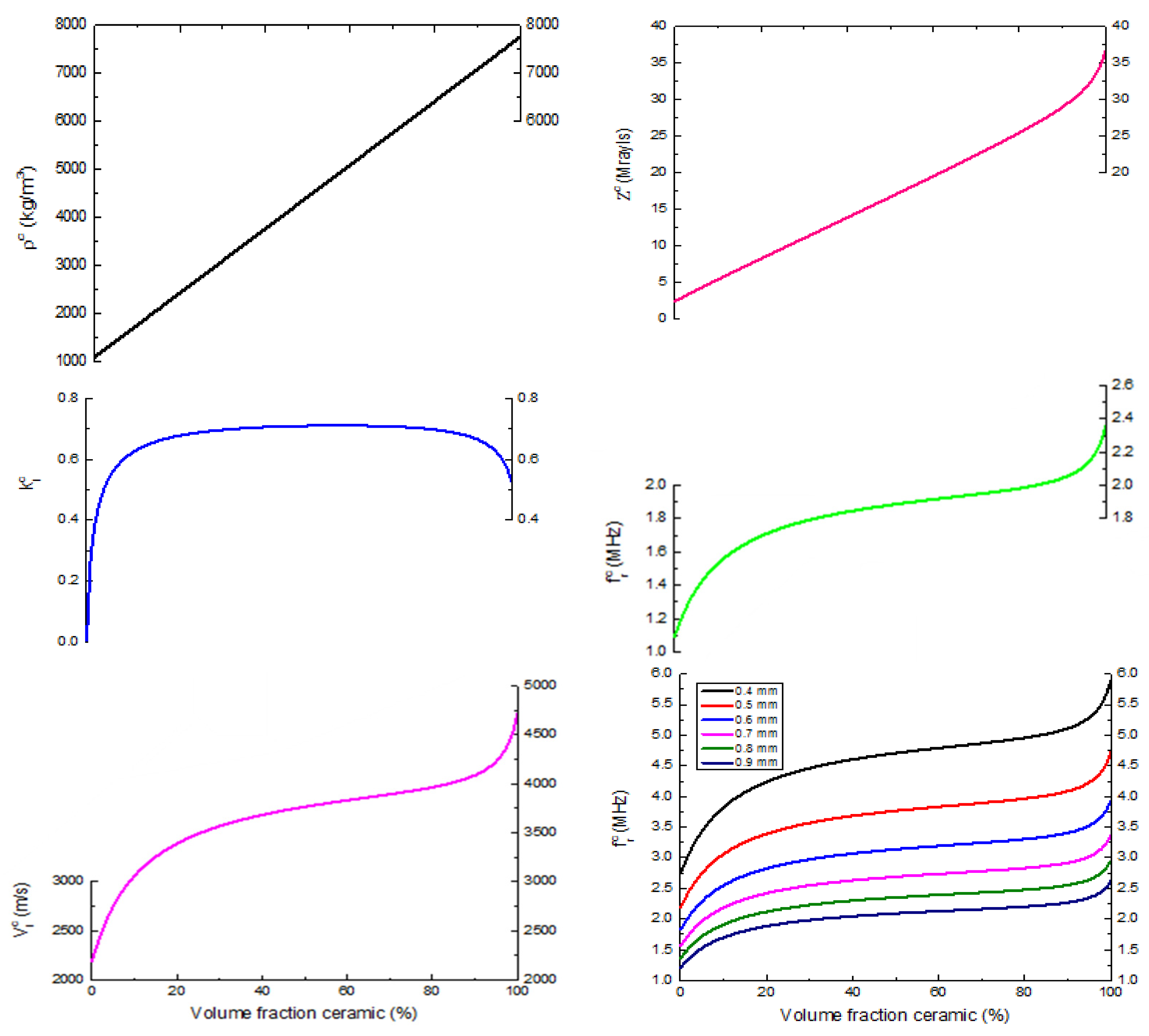
2.1. Design of Active Piezoelectric Material Dimension

Mode-coupling may occur in resonators with multi-axial resonance frequency modes at the target frequency, which couples with the desired axial mode of the transducer and causes significant performance degradation [14]. Therefore, the design of an active piezoelectric column should be focused on avoiding the mode-coupling effect. In this work, the mode-coupling theory was adopted during the design process.
Figure 1a shows a rectangular solid beam with length N in the y-direction, width L in the x-direction, and height H in the z-direction, which represents a piezoceramic/epoxy 2-2 composite with its z-axis as the polarization direction and with the electrodes on the surface occurring normally on the z-axis. If the beam is long enough such that N » L and H, then the resonance frequency determined by the length dimension (=N) will appear at frequencies that are far below those of the lateral (=L) and beam (=H) modes. Therefore, the width-to-height ratio G (=L/H) is the key factor to avoid the mode-coupling effect at high frequencies. According to mode-coupling theory, the biquadratic frequency equation of the rectangular solid beam can be expressed as [7]
( f a 2 f 2 ) ( f b 2 f 2 ) = f a 2 f b 2 γ 2  
where
  f a = 1 2 L C 11 ρ
and
f b = 1 2 H C 33 ρ  
which are the resonance frequencies of the uncoupled lateral (=L) and beam (=H) modes, respectively; γ = c 13 / c 11 c 33 is the coupling coefficient; c11, c13, and c33 are the elastic stiffness coefficients; and ρ is the density. Equation (1) provides the following solutions:
f ± H = C 33 8 ρ ( 1 + 1 G 2 C 11 C 33 ± ( 1 + 1 G 2 C 11 C 33 ) 2 4 G 2 C 11 C 33 ( 1 γ 2 ) )
where f and f+ describe the lower and upper frequency branches, respectively. Additionally, the coupled lateral (=fL) and beam (=fH) resonance frequencies are controlled by these two frequency branches in terms of G. Therefore, the theoretical curves of the coupled (f+ and f) and uncoupled (fa and fb) resonance frequencies at different G can be created by substituting the related piezoelectric properties into Equations (2) and (3), respectively.
Using the electromechanical properties of PZT-5H listed in Table 2, the theoretical curves of the coupled and uncoupled resonance frequencies in terms of G are plotted for the short-circuit conditions in Figure 1b. In the case of G < 0.5, the PZT-5H beam is a tall and narrow beam, resulting in the coupled lateral mode resonance frequency (=fL) appearing at a frequency that is well above the coupled beam mode resonance frequency (=fH) and that is not mode-coupled with fH. In the case of G > 3, the PZT-5H beam takes the shape of a thin and wide plate, resulting in the coupled lateral mode resonance frequency (=fL) appearing at a frequency that is well below the coupled beam mode resonance frequency (=fH) and that is not mode-coupled with fH. However, in the case of 0.5 < G < 3, significant mode coupling occurs between fL and fH. Therefore, in order to produce a high-performance ultrasonic transducer, the use of uncoupled and low-frequency beam modes (i.e., fH) with a higher electromechanical coupling factor (=k33) is more advantageous, and the layout of a PZT/epoxy 2-2 composite with G < 0.5 is the first design standard in this work.

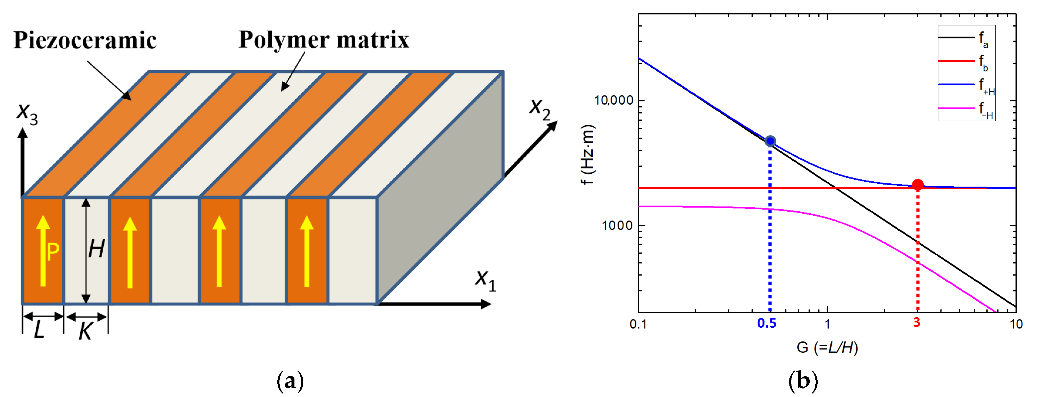
2.2. Design of 2-2 Composite Transducer
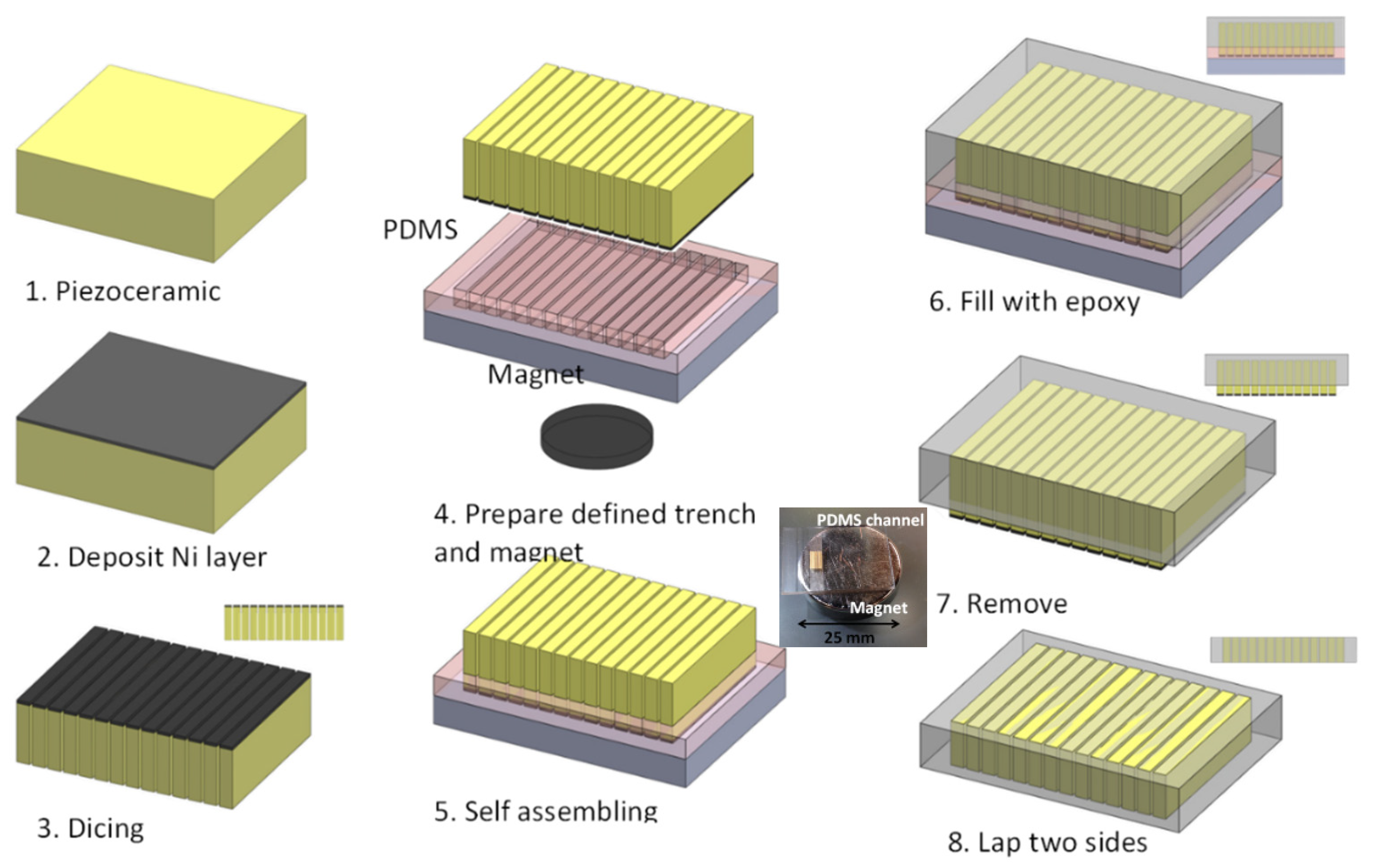
For desired transducer performance: k33, center frequency (fc), and the acoustic impedance (Z), the dimensions of the 2-2 composite should be considered. Specifically, due to the biphasic nature and the large differences in the material properties between the ceramic and the polymer, the surface displacement is often non-uniform, so accurately predicting composite transducer performance is challenging [15].
The most used method for designing piezoelectric composite transducers is the effective medium model, which can be derived from the assumption that a composite is a homogeneous medium with new effective material parameters so long as the beam size and spacing are sufficiently fine compared with all of the relevant acoustic wavelengths [16,17]. We followed the same procedure as a previous paper [16] and used all of the proposed assumptions to derive the effective parameters of a 2-2 composite:
c ¯ 33 E = V [ c 33 E 2 V ( c 13 E c 12 ) 2 V ( c 11 + c 12 ) + V ( c 11 E + c 12 E ) ] + V c 11
e ¯ 33 = V [ e 33   2 V e 31 ( c 13 E c 12 ) V ( c 11 + c 12 ) + V ( c 11 E + c 12 E ) ]
ϵ ¯ 33 S = V [ ϵ 33 S + 2 V ( e 31 ) 2 V ( c 11 + c 12 ) + V ( c 11 E + c 12 E ) ] + V ϵ 11  
c ¯ 33 D = c ¯ 33 E + e ¯ 33 2 / ϵ ¯ 33 S
ρ ¯ = V ρ c + V ρ p
In the above expressions, the upper bar denotes the composite, in which cij, eij, and εij are the elastic stiffness, piezoelectric constant, and dielectric constant, and the superscripts E and S refer to the constant electric field and strain quantities, respectively. V and V′ are the volume fractions of the piezoceramic and polymer, where V + V′ = 1, and ρc and ρp are the densities of the ceramic and the polymer, respectively. Finally, all of the relevant effective parameters for the thickness mode can be derived from the conventional definition
k ¯ 33 = e ¯ 33 / ( c ¯ 33 D ϵ ¯ 33 S ) 1 2
Z ¯ = ( c ¯ 33 D ρ ¯ ) 1 / 2      
v ¯ l = ( c ¯ 33 D / ρ ¯ ) 1 / 2        
f r = v ¯ l / 2 H
where L and vl are the thickness of the composite in the poling (x3) direction and the longitudinal wave speed, and fr is the resonance frequency calculated by the effective medium model. Using the above equations, we derived effective 2-2 composite parameters such as the density, electromechanical coupling coefficient, longitudinal wave speed, acoustic impedance, and thickness resonance frequency as a function of the volume fractions.

3. Fabrication

Figure 2 illustrates the fabrication process for a 2-2 composite transducer. We chose PZT-5H as the active material and deposited one nickel (Ni) layer on the top surface of the PZT-5H as a magnetic material. To generate a high magnetic force, the thickness of the Ni needed be considered. Ni electro plating was applied to deposit 10 um of Ni. After deposition, the piezoceramic with Ni layer deposited on top if it was diced into the pre-determined size (200 μm × 500 μm × 5 mm). Before using a magnet for self-assembly, a PDMS mold with grating patterns carved into it with a saw needed to be prepared. The grating pattern is the key element for this magnetic force assembly technique. The width of the grating was about 210 μm, which was a little bit larger than what was required for the piezoceramic size in order to fit the piezo pillars directly into the gratings; the pitch of gratings was about 320 μm. with a magnet with 25 mm diameter was applied for the self-assembly process. Because of the strong magnetic force, the piezo pillars with the deposited Ni layer were able to move into the grating easily. Once the piezo pillars were perfectly located in the gratings, they could no longer move from side to side. Then, we filled in the mold with epoxy so that the whole sample was covered. One of the properties of epoxy is its good liquidity, and this allowed it to easily fill in the gaps. After the epoxy had cured, the PDMS mold could be remove by it peeling off. Additionally, for the last step, two side of sample should be lapped down to 400 μm, and an electrode layer should be deposited.

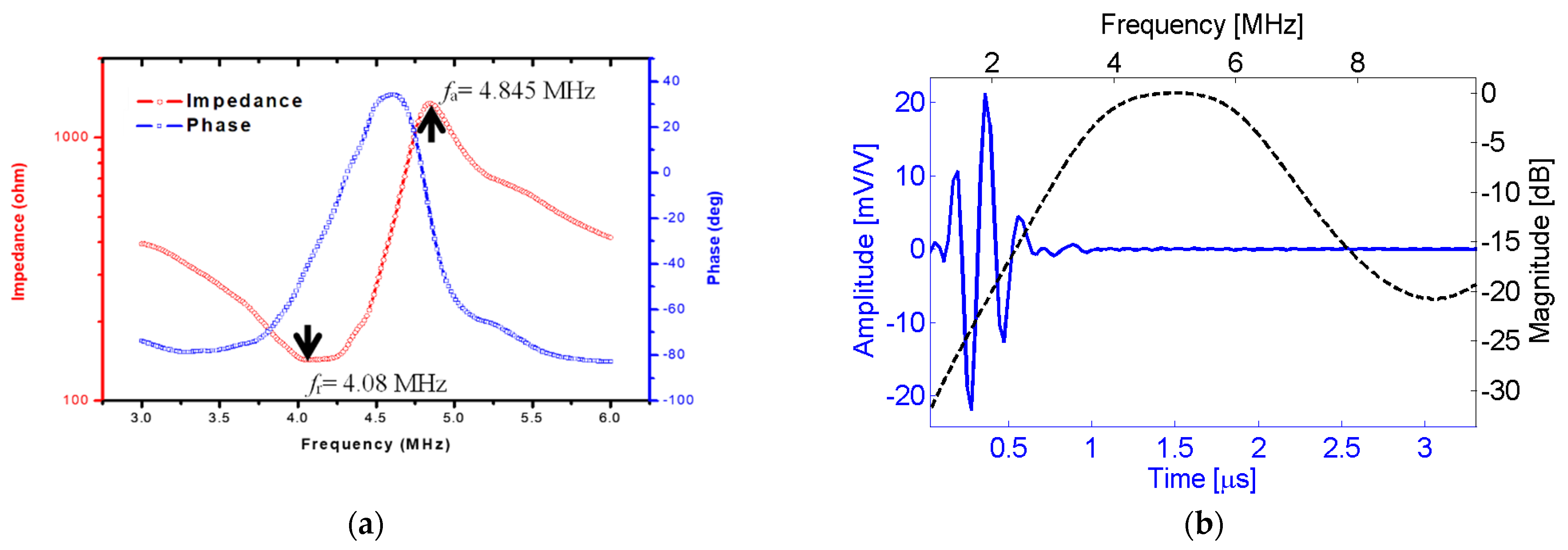
4. Results and Discussion

Figure 3 shows that the desired properties and performance of the obtained 2-2 composite transducer, such as the thickness-mode electromechanical coupling coefficient (k33 ≈ 70%), acoustic impedance (Z < 20 MRayl), and thickness resonance frequency (fr ≈ 5 MHz), could be obtained from the piezoceramic volume fraction (V = 60%) and from the thickness of the composite (H = 0.4 mm). Therefore, based on the first design criterion of the mode-coupling theory, G < 0.5, the length of the piezoceramic material (=L) should be less than 0.2 mm, and the kerf width (=K) should be 0.12 mm to so that a 60% volume fraction can be obtained for the composite. The acoustic characteristics of the fabricated transducer are listed in Table 3.
We used an impedance analyzer to measure the relationship between the impedance, phase, and frequency. Figure 4a. shows that the resonance peak and anti-resonance peak are 4.08 MHz and 4.845 MHz, respectively. Based on the calculations, the electromechanical coupling factor (kt) is about 0.58. Additionally, no further spurious resonant modes are observed for the electrical impedance and phase angle in Figure 4a, indicating the advantage of the 2-2 composite in preventing the mode coupling effect. Transducer performance was measured using the pulse–echo method (Figure 4b). The transducer was positioned in a tank with degassed water. A steel block was placed 20 mm away from the transducer to act as the reflection target. An electrical pulser/receiver (generated by a square wave) was used to excite the transducer at 100 V. The reflected impulse was measured and stored by the oscilloscope. The obtained impulse response was then used to determine the sensitivity and bandwidth. The center frequency was 4.97 MHz, the −6 dB fractional bandwidth was 65.2%, and the acoustic impedance was lower than 20 MRayl, comparable to our target performance results for a transducer created based on the design criteria.

5. Conclusions

In this work, magnetic force assembly is introduced for the fabrication of a 2-2 composite transducer as a novel and low-cost fabrication method. The magnetic force was able to manipulate the sample into the desired position easily. Additionally, the design of the dimensions and the performance of the fabricated transducer are shown to demonstrate the potential of this technique. The experimental results indicate that the electromechanical coupling factor and the −6 dB fractional bandwidth of the prototyped composite achieve values of 0.58 and 65.2%, respectively, which are comparable those of traditional 1-3 piezoelectric composites. These results indicate that the designed prototype transducers can achieve acceptable sensitivity and bandwidth performance for biomedical sensor applications, such as ultrasound imaging, as well as for application such as nondestructive testing (NDT) and structural health monitoring (SHM) as well.

Funding

This work was partly supported by the 2022 research fund of Korea Military Academy (Hwarangdae Research Institute) and the National Research Foundation of Korea Grant funded by the Korean Government (2019R1G1A109954513).

Institutional Review Board Statement

Not applicable.

Informed Consent Statement

Not applicable.

Data Availability Statement

Not applicable.

Acknowledgments

The author would like to thank Wei-Yi Chang for his assistance and valuable insight and suggestions.

Conflicts of Interest

The author declares no conflict of interest.

References

  1. Cochran, S.; Parker, M.; Marin-Franch, P. Ultrabroadband Single Crystal Composite Transducers for Underwater Ultrasound. Proc. IEEE Ultrason. Symp. 2005, 1, 231–234. [Google Scholar] [CrossRef]
  2. Marin-Franch, P.; Pettigrew, I.; Parker, M.; Kirk, K.J.; Cochran, S. Piezocrystal-Polymer Composites: New Materials for Transducers for Ultrasonic NDT. Insight Non-Destr. Test. Cond. Monit. 2004, 46, 653–657. [Google Scholar] [CrossRef]
  3. Ebbini, E.S. Self-Guided Ultrasound Phased Arrays for Noninvasive Surgery. Proc. SPIE 2001, 4247, 30–40. [Google Scholar]
  4. Kim, J.; Li, S.; Kasoji, S.; Dayton, P.A.; Jiang, X. Phantom Evaluation of Stacked-Type Dual-Frequency 1-3 Composite Transducers: A Feasibility Study on Intracavitary Acoustic Angiography. Ultrasonics 2015, 63, 7–15. [Google Scholar] [CrossRef] [PubMed]
  5. Sun, R.; Wang, L.; Zhang, Y.; Zhong, C. Characterization of 1-3 Piezoelectric Composite with a 3-Tier Polymer Structure. Materials 2020, 13, 397. [Google Scholar] [CrossRef] [PubMed] [Green Version]
  6. Newnham, R.E.; Skinner, D.P.; Cross, L.E. Connectivity and Piezoelectric-Pyroelectric Composites. Mater. Res. Bull. 1978, 9, 198–200. [Google Scholar] [CrossRef]
  7. Wang, W.; Or, S.W.; Yue, Q.; Zhang, Y.; Jiao, J.; Leung, C.M.; Zhao, X.; Luo, H. Ternary Piezoelectric Single-Crystal PIMNT Based 2-2 Composite for Ultrasonic Transducer Applications. Sens. Actuators A Phys. 2013, 196, 70–77. [Google Scholar] [CrossRef]
  8. Xu, D.; Cheng, X.; Huang, S.; Jiang, M. Electromechanical Properties of 2-2 Cement Based Piezoelectric Composite. Curr. Appl. Phys. 2009, 9, 816–819. [Google Scholar] [CrossRef]
  9. Lopatin, S.; Lopatina, I.; Lisnevskaya, I. Magnetoelectric PZT/Ferrite Composite Materials. Ferroelectrics 1994, 162, 63–68. [Google Scholar] [CrossRef]
  10. McNulty, T.F.; Mohammadi, F.; Bandyopadhyay, A.; Shanefield, D.J.; Danforth, S.C.; Safari, A. Development of a Binder Formulation for Fused Deposition of Ceramics. Rapid Prototyp. J. 1998, 4, 144–150. [Google Scholar] [CrossRef] [Green Version]
  11. Zhang, Y.; Jiang, Y.; Lin, X.; Xie, R.; Zhou, K.; Button, T.W.; Zhang, D. Fine-Scaled Piezoelectric Ceramic/Polymer 2-2 Composites for High-Frequency Transducer. J. Am. Ceram. Soc. 2014, 97, 1060–1064. [Google Scholar] [CrossRef]
  12. Li, K.; Zeng, D.W.; Yung, K.C.; Chan, H.L.W.; Choy, C.L. Study on Ceramic/Polymer Composite Fabricated by Laser Cutting. Mater. Chem. Phys. 2002, 75, 147–150. [Google Scholar] [CrossRef]
  13. Yin, J.; Lukacs, M.; Harasievvicz, K.; Foster, S. Ultra-Fine Piezoelectric Composites for High Frequency Ultrasonic Transducers. Proc. IEEE Ultrason. Symp. 2004, 3, 1962–1965. [Google Scholar] [CrossRef]
  14. Or, S.W.; Chan, H.L.W. Mode Coupling in Lead Zirconate Titanate/Epoxy 1-3 Piezocomposite Rings. J. Appl. Phys. 2001, 90, 4122–4129. [Google Scholar] [CrossRef] [Green Version]
  15. Qi, W.; Cao, W. Finite Element Analysis and Experimental Studies on the Thickness Resonance of Piezocomposite Transducers. Ultrason. Imaging 1996, 18, 1–9. [Google Scholar] [CrossRef] [PubMed]
  16. Smith, W.A.; Auld, B.A. Modeling 1–3 Composite Piezoelectrics: Thickness-Mode Oscillations. IEEE Trans. Ultrason. Ferroelectr. Freq. Control 1991, 38, 40–47. [Google Scholar] [CrossRef] [PubMed]
  17. Kim, T.; Kim, J.; Jiang, X. Transit Time Difference Flowmeter for Intravenous Flow Rate Measurement Using 1-3 Piezoelectric Composite Transducers. IEEE Sens. J. 2017, 17, 5741–5748. [Google Scholar] [CrossRef]
Figure 1. (a) Configuration of the 2-2 composite investigated in this study; (b) theoretical curves of the coupled and uncoupled resonance frequency as a function of G.
Crystals 12 00740 g001
Figure 2. The fabrication process of a 2-2 composite by magnetic force-assisted self-assembly.
Crystals 12 00740 g002
Figure 3. Variation in the effective properties with piezoceramic volume fraction.
Crystals 12 00740 g003
Figure 4. (a) Resonance and anti-resonance peaks; (b) pulse–echo response of 2-2 composite fabricated by magnetic force-assisted self-assembly.
Crystals 12 00740 g004
Table 1. Required 2-2 composite transducer performance.
k33Center Freq.Acoustic Impedance(Z)Bandwidth
>60%5 MHz<20 MRayl>65%
Table 2. Material properties of PZT-5H and Epo-Tek 301 epoxy for 2-2 composite design.
PZT-5HEpoxy
C11E (1010 N/m2)15.10.53
C12E (1010 N/m2)9.800.31
C13E (1010 N/m2)9.60-
C33E (1010 N/m2)12.4-
ρ (kg/m3)77501100
ε33s017004
k33 (%)75-
kt (%)52-
Table 3. Acoustic properties of fabricated 2-2 composite.
BackingActiveMatching_0Matching_1
MaterialE-solderPZT-5H compositeEPO-TEKPayleneC
Longitudinal velocity (m/s)1850383327002770
ρ (kg/m3)3200509016701140
Acoustic impedance (MRayl)5.9219.54.513.16
Publisher’s Note: MDPI stays neutral with regard to jurisdictional claims in published maps and institutional affiliations.

