Abstract
In the current process for additive manufacturing of continuous carbon fiber reinforced resin matrix composites, the fiber and resin matrix are fed into the molten chamber, and then impregnated and compounded in the original position, and finally extruded and deposited on the substrate. It is difficult to control the ratio of fiber and resin, and to achieve good interface fusion, which results in an unsatisfactory enhancement effect. Therefore, an additive manufacturing process based on continuous carbon fiber reinforced polylactic acid composite prepreg filament was explored in this study. The effects of various process parameters on the formability of composites were studied through systematic process experiments. The results showed that the process parameters of additive manufacturing have a systematic influence on the forming quality, accuracy and efficiency, and on the mechanical properties of CFRP. Through the experimental optimization of various process parameters, a continuous and stable forming process was achieved when the nozzle aperture was 0.8 mm, the nozzle printing temperature was 240 °C, the substrate temperature was 60 °C, the wire feeding speed was 5 mm/s, the nozzle moving speed was 5 mm/s, the path bonding rate was 40%, and the printing layer thickness was 0.7 mm. Based on the optimized process parameters, direct additive manufacturing of a lightweight and high-strength composite cellular load-bearing structure could be realized. Its volume fraction of carbon fiber was approximately 7.7%, and the tensile strength was up to 224.3 MPa.
1. Introduction
Recently, emerging additive manufacturing technology [1,2,3] has provided the possibility of small-batch and customized manufacturing of composite components with complex structures and special functional requirements. For example, Valerio et al. [4,5] investigated the application of an additive manufactured hybrid metal composite shock absorber panel to a military seat ejection system, and studied the effects of core microstructure on the energy absorbing capabilities of sandwich panels intended for additive manufacturing. Fused deposition molding, a widely used additive manufacturing technology, has excellent potential for rapidly manufacturing fiber reinforced resin matrix composite components, and has become a research hotspot. The most common materials used in this type of forming process are amorphous thermoplastics, with acrylonitrile–butadiene–styrene (ABS) and polylactic acid (PLA) being the most common [6,7]. Recently, a few studies have reported on the use of short- or long- fiber reinforced thermal plastics as the feedstock of the FDM process. Tekinalp et al. [8], Zhong et al. [9], and Ning et al. [10], investigated short fiber reinforced acrylonitrile–butadiene–styrene (ABS) composites as a feedstock for 3D printing in terms of their processibility, microstructure, and mechanical performance. Gray et al. [11,12] developed polypropylene (PP) strands reinforced with thermotropic liquid crystalline polymer (TLCP) fibers for an FDM process, and investigated the effects of FDM processing conditions on short TLCP fiber reinforced parts. Luo et al. [13] investigated the impregnation and interlayer bonding behaviors of 3D-printed continuous carbon fiber reinforced poly-ether-ketone composites.
Continuous carbon fiber reinforced resin matrix composites (CCFRRMCs) have the advantages of high specific strength, high specific stiffness, low thermal expansion coefficient, excellent fatigue performance, and corrosion resistance, and are critical substrates for the main load-bearing structures and high-precision substructures of satellites and spacecraft. CCFRRMCs have been also used in the manufacturing process for satellite load-bearing cylinders, rocket motor cases, and other components [14,15]. At present, the traditional forming processes of CCFRRMC components mainly include laying forming [16], molding forming [17,18], and weaving forming [19,20]. It not only has complicated processing procedures, a long processing cycle, and high manufacturing costs, but it also cannot achieve flexible manufacturing of parts with complex structures. Therefore, it has become the bottleneck for composite component processing in the aerospace field.
Based on the fusion deposition molding method, most research institutions are currently feeding continuous carbon fiber dry filaments and resin matrix filaments into the heating block fusion chamber, which are impregnated and compounded in the original position, and then extruded from the end of the nozzle and deposited layer by layer. Li et al. [21] investigated the rapid prototyping of continuous carbon fiber reinforced polylactic acid composites for 3D printing, and performed comparison experiments of printed samples with or without a preprocessed carbon fiber bundle; the properties were also measured. Tian et al. [22] researched the interface and performance of 3D printed continuous carbon fiber reinforced PLA composites. Wang et al. [23,24] improved the performance of continuous carbon fiber reinforced plastic composites by optimizing the printing strategy, and they also investigated the fiber–matrix impregnation behavior during the additive manufacturing process. Liang et al. [25] adopted a bionic structure design to further improve the impact resistance of additive manufacturing composites. However, due to the poor rigidity of carbon fiber dry filaments, it is difficult to precisely control the ratio of fiber to resin during the composite process. In addition, the impregnation time for fiber and resin in the melting chamber is short, and a favorable interface combination cannot be acquired, making it difficult to provide the desired reinforcement when using continuous carbon fibers within composite parts.
In order to further improve the mechanical properties of fused deposition molding CCFRRMCs, we employed pre-prepared continuous carbon fiber/PLA composite filaments to systematically investigate the effects of printing speeds, nozzle height, path bonding rate, printing temperature, printing layer thickness, and other parameters on the forming quality of single channel, single-layer, and solid composites. As a result, direct additive manufacturing of honeycomb CCFRRMCs was realized. Furthermore, the research results reported in this paper reveal the coupling mechanism for multiple process parameters in the additive manufacturing process of CCFRRMCs, and lay the foundation for the optimization of each process parameter. This study achieved structure–function integrated design for lightweight composite parts with complex structures and high strengths for use in the aerospace field.
2. Materials and Methods
2.1. Materials
In the present research, the 1 mm diameter continuous carbon fiber reinforced resin matrix composite filaments were all prepared using self-developed filament-making equipment. Polyacrylonitrile T300 (PAN) 1K carbon fiber bundles from TORAY Corp. in Japan, with a monofilament diameter of 6~8 μm, were used as the raw material for the continuous carbon fiber. The raw material for the thermoplastic resin was polylactic acid (PLA) pellets, type 4032D, from NATUREWORKS Corp. in the USA, with a melting temperature of 175 °C.
For the preparation of the composite filaments, first the surface of the carbon fiber was treated with a sizing agent. A bundle of 1K treated carbon fiber was then fed into the filament-making equipment under a certain tension. In this equipment, the carbon fiber was spread evenly onto the surface of a set of impregnated rollers. At the same time, the molten PLA in the impregnation cavity was allowed to penetrate into the filament under the continuous high pressure. Finally, the impregnated carbon fibers were pulled out from a certain diameter outlet and cured for a certain time to form the final composite filaments.
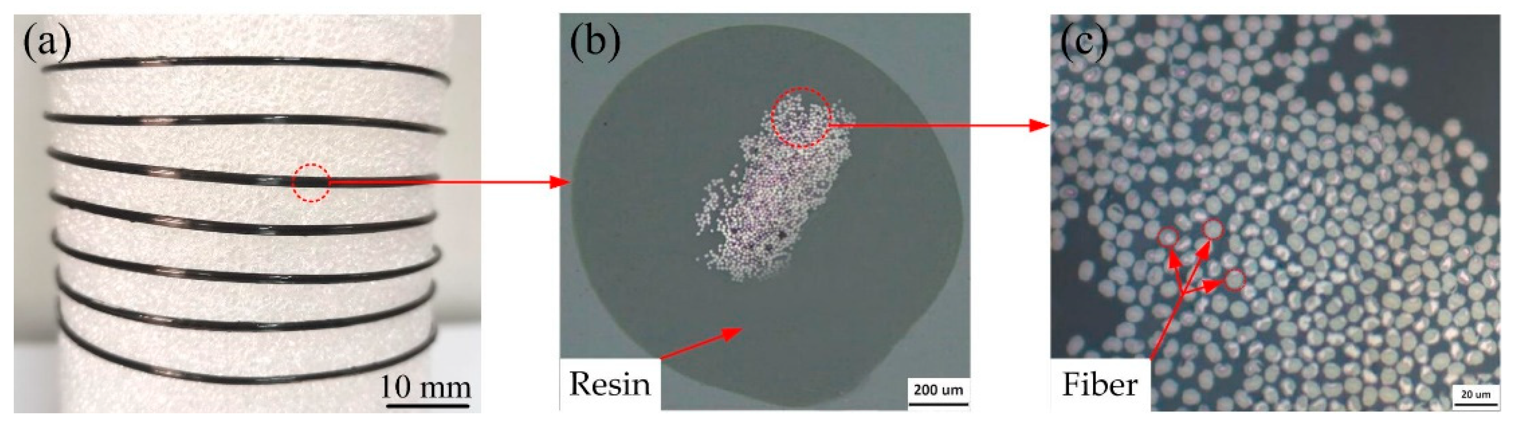
The prepared composite filaments and their cross-sectional microscopic morphology are shown in Figure 1. It can be seen that PLA rings wrap the continuous carbon fiber filament bundles, and the PLA forms an effective homogeneous impregnation between the carbon fiber monofilaments. The tensioning state of the continuous carbon fibers is difficult to control during the preparation of the composite filaments and therefore, the stability of the neutral distribution of continuous carbon fiber in the composite wire was imperfect. However, this problem can be compensated for during the secondary melting and extrusion of the composite filaments.
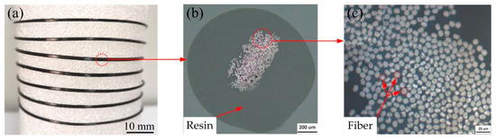
Figure 1.
(a) Continuous carbon fiber reinforced resin matrix composite wire; (b) composite wire microstructure (cross section); (c) distribution of fibers in the resin.
2.2. Methods
2.2.1. Additive Manufacturing Process for Continuous Carbon Fiber Reinforced Resin Matrix Composites
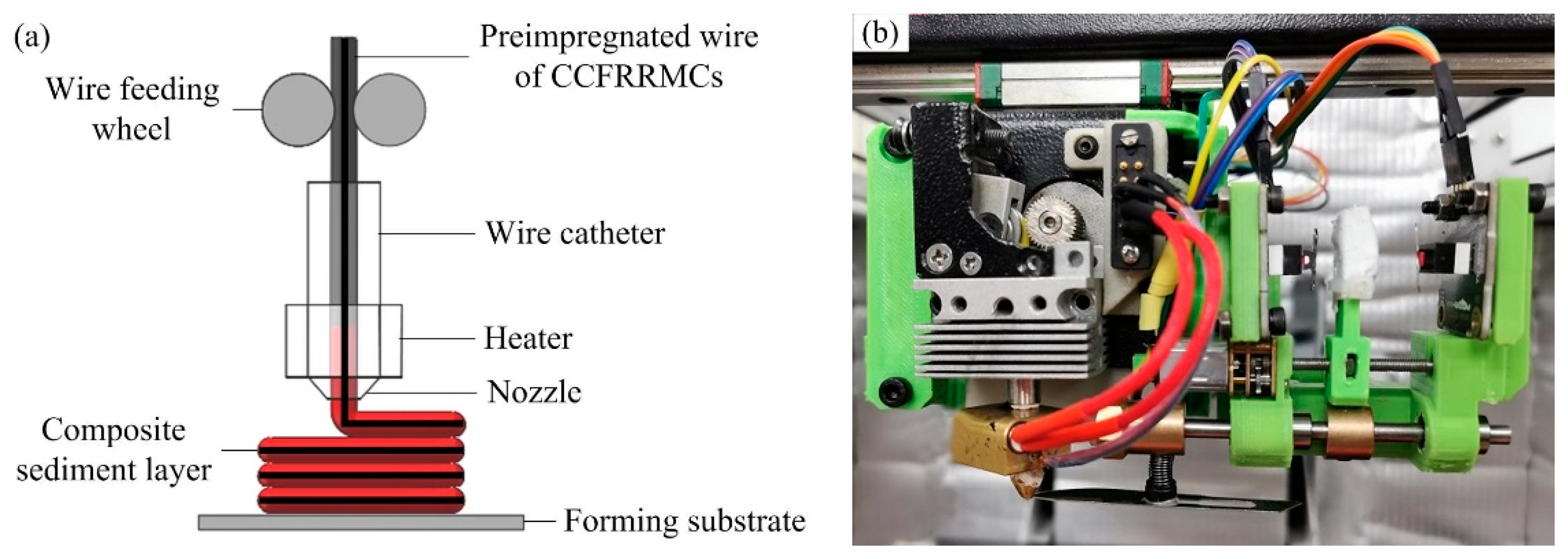
The process for additive manufacturing of CCFRRMCs used in this study is shown in Figure 2a. The prepreg composite filament was driven by the wire feeding wheel into the melt extrusion nozzle at the bottom, and was melted by the heating block at the bottom of the nozzle in real time and with high efficiency. The molten composite material was extruded via the nozzle end under the driving force of the solid wire at the upper end. The nozzle moved according to the section profile and filling trajectory of the preprepared parts, so that the composite materials were selectively stacked on the substrate, layer by layer. Finally, complete CCFRRMC parts with a specific complex shape were obtained. Figure 2b shows the extrusion nozzle used in the experimental process.
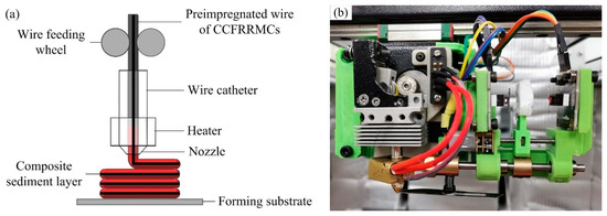
Figure 2.
(a) Additive manufacturing process for continuous carbon fiber reinforced resin matrix composites; (b) the composite wire melting extrusion nozzle.
2.2.2. Single Channel Composite Forming Experiment
Additive manufacturing is a systematic forming process in which materials are formed from point to line, from line to surface, and from surface to body. The process of forming lines from points is the basis of additive manufacturing technology. Therefore, this study first used continuous carbon fiber/polylactic acid composite wire to conduct a single channel forming experiment to study the relationship between wire feeding speed, nozzle moving speed, the influence of nozzle height to substrate height on forming quality and on the single channel deposition path width of the single channel composite.
Based on reading many references and carrying out preliminary process experiments, the process parameters in the single channel forming experiment were determined as follows [21,22,23,24,25]: nozzle aperture 0.8 mm, nozzle printing temperature 220 °C, and substrate temperature 60 °C; and the range of the study parameters was as follows: wire feeding speed 3~10 mm/s, moving speed of the nozzle 3~10 mm/s, and the height of the nozzle from the substrate 0.3~1 mm.
2.2.3. Forming Experiment of Monolayer Composite
Path bonding rate affects the surface quality, fiber volume fraction, and mechanical properties of composite material. Therefore, based on the single channel forming experiment, we conducted an experiment on the forming process of the single-layer composite material to investigate the path bonding rate parameters. The surface quality of the monolayer composite was studied under the conditions of wire feeding speed of 5 mm/s, moving speed of the nozzle of 5 mm/s, and height of the nozzle from the substrate of 0.7 mm.
Figure 3 illustrates the overlap zone formed between two adjacent deposition paths. In the Figure, w is the single path deposition path width, l is the width of the lap zone, and the path bonding rate can be expressed as:
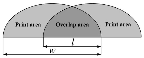
Figure 3.
Schematic diagram of the overlap region formed between two adjacent trajectories.
The range of the path overlap rate studied in the experiment was 10–60%.
2.2.4. Composite Material Solid Forming Experiment
The nozzle printing temperature and printing layer thickness significantly affect the forming accuracy, forming efficiency, and mechanical properties of composites. Therefore, based on the optimized path bonding rate, experiments on solid forming of composite materials were carried out for these two process parameters. In accordance with standard GB/T 100.44-2006 (Determination of tensile properties of plastics—Part 4: Isotropic and orthotropic fiber reinforced composite material), three layers of composite tensile test specimens were prepared under different nozzle print temperatures and layer thickness parameters. The tensile properties of the specimens were tested using an electronic universal testing machine (UTM6503, SANSI ZHONGHENG Technology Corp, Shenzhen, China), and the effects of printing temperature and printing layer thickness on the tensile properties of solid specimens were studied. At the same time, the interlaminar bonding, the carbon fiber and polylactic acid composite situation, and the distribution of carbon fiber at the fracture point of the tensile specimen were observed using a scanning electron microscope (S-4800, HITACHI Corp., Hitachi, Japan), to further explore the effect of printing temperature and printing layer thickness on the tensile properties of solid specimens.
The range of printing temperatures studied in the experiment was 200~260 °C, and the range of printing layer thicknesses was 0.6~0.9 mm.
2.2.5. Forming Experiment for Composite Cellular Load-Bearing Structure
Finally, we verified the practicality and stability of the additive manufacturing process based on continuous carbon fiber reinforced resin matrix composite prepreg filaments. Based on the optimized parameters, nozzle aperture was 0.8 mm, nozzle printing temperature was 240 °C, substrate temperature was 60 °C, wire feeding speed was 5 mm/s, nozzle moving speed was 5 mm/s, path bonding rate was 40% and printing layer thickness was 0.7 mm, with the aim to realize the formation of typical honeycomb load-bearing structures used in the aerospace field.
3. Experimental Results and Analysis
3.1. Experimental Results and Analysis of Single Channel Composite Forming
Figure 4 shows the theoretical distribution state of continuous carbon fiber in the molten chamber at the end of the nozzle, and the corresponding images of the actual single channel forming when the wire feeding speed was set at 5 mm/s and different moving speeds of the nozzle were adopted.
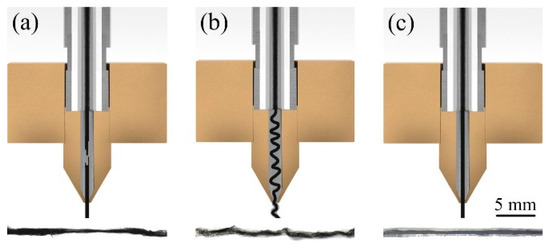
Figure 4.
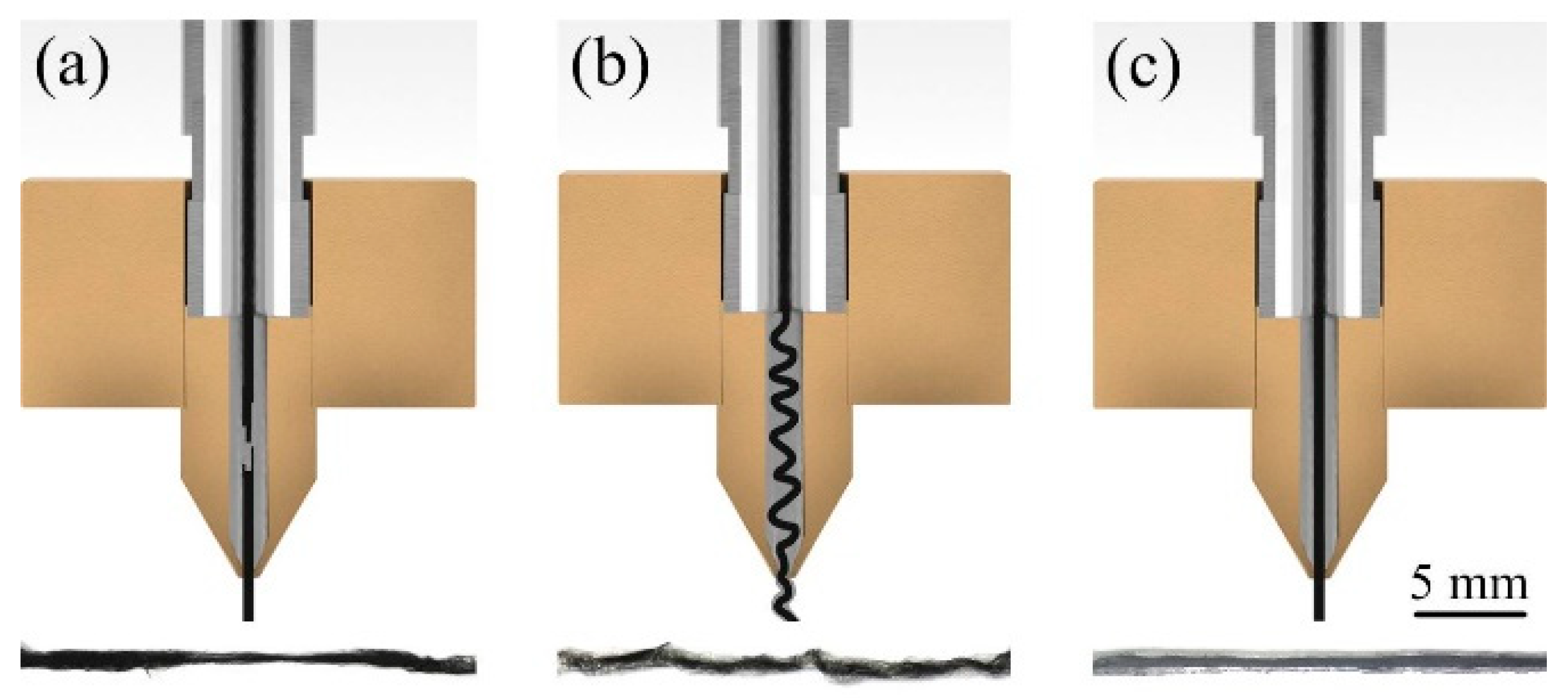
(a) The theoretical distribution state of continuous carbon fiber in nozzle melting chamber and the corresponding image of actual single channel when the the moving speed of the nozzle was greater than the wire feeding speed; (b) the moving speed of the nozzle was smaller than the wire feeding speed; (c) the moving speed of the nozzle was equal to the wire feeding speed.With equal values for the wire feed speed and nozzle moving speed, it is often necessary to increase the speed to improve the forming efficiency, but a faster wire feed and nozzle moving speed will also impact the single-pass forming quality.
As shown in Figure 4a, when the moving speed of the nozzle was 7 mm/s higher than the set wire feeding speed, the length of carbon fiber provided by the wire feeding pair wheel per unit time was less than the length of carbon fiber required by single path filling. At this moment, the drag force of the carbon fiber in the molten cavity caused by the composite material which has been deposited and solidified at the end of the nozzle was also increasing. Finally, there were breaks in the continuous carbon fiber in the nozzle melting chamber, which affected the single channel forming quality. In the opposite case, Figure 4b shows that when the nozzle moving speed was set at 3 mm/s lower than the wire feed speed, the carbon fiber length provided by the wire was longer than the single channel path. Such a case caused the over-accumulation problem of continuous carbon fiber in the nozzle melting chamber, which is easy to cause the nozzle blockage and affect the single channel forming quality. Figure 4c shows the situation when the nozzle moving speed was equal to the set speed, 5 mm/s. Per unit time, the carbon fiber length provided by the wire was equal to the length of the single channel path. Now, homogeneous and continuous carbon fiber was distributed in the nozzle melt chamber and deposited in the middle of the single channel path. Single channel forming quality was also better.
In summary, in order to get a good single-pass forming quality, the wire feed speed needed to be set at the same value as the nozzle moving speed.
Figure 5 shows images of a single path forming when the moving speed of the nozzle is unequal to the wire feed rate. It can be seen that when the moving velocity of the wire feeder and the nozzle is relatively small at 5 mm/s, as shown in Figure 5a, the edge of the single channel deposition path is relatively uniform. When the moving velocity of the wire feed and nozzle is relatively large at 10 mm/s, as shown in Figure 5b, the edge uniformity of the single channel deposition path is poor. The reasons were as follows: on the one hand, at a higher wire feeding speed, the volume of molten polylactic acid extruded from the nozzle will increase per unit time, and the extrusion stability will also decrease, resulting in an uneven deposition path edge. On the other hand, the stability of the height between the nozzle and the substrate decreases due to the fast-moving speed of the nozzle, which further aggravates the inhomogeneity of the edge of the single channel deposition path.
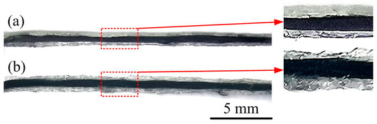
Figure 5.
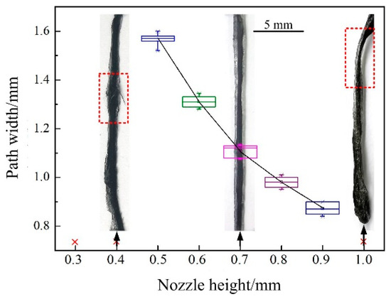
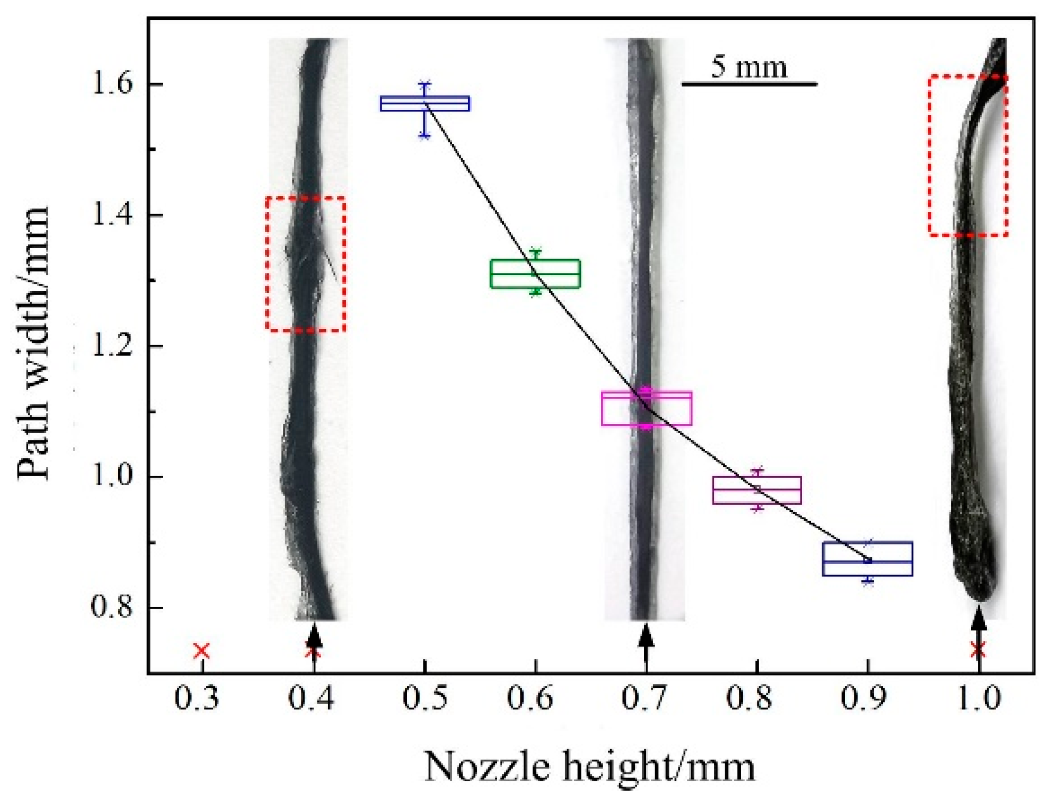
(a) Photograph of single channel forming path when the nozzle moving speed and wire feeding speed were both 5 mm/s; (b) the nozzle moving speed and wire feeding speed were both 10 mm/s. In the single channel composite forming process, the height of the nozzle from the substrate also had a significant impact on the single channel deposition path width and forming quality. Therefore, we set the wire feed speed and nozzle moving speed at 5 mm/s and tested different nozzle height conditions in single-pass forming experiments. Figure 6 shows the resulting experimental data and forming paths.
When the height of the nozzle was small (0.3~0.4 mm), the deposition path was uneven, resulting in poor uniformity of the path and carbon fiber that is easy to scrape off. When the nozzle height was extended (1 mm), the extruded composite could not be effectively compacted, so the deposition path could not adhere firmly to the substrate, thus affecting the subsequent forming process. When the height of the nozzle was in an appropriate range (0.5~0.9 mm), a uniform deposition path was obtained; the width of the deposition path decreased with an increase in the of the height of the nozzle.
3.2. Experimental Results and Analysis of Single Layer Composite Forming
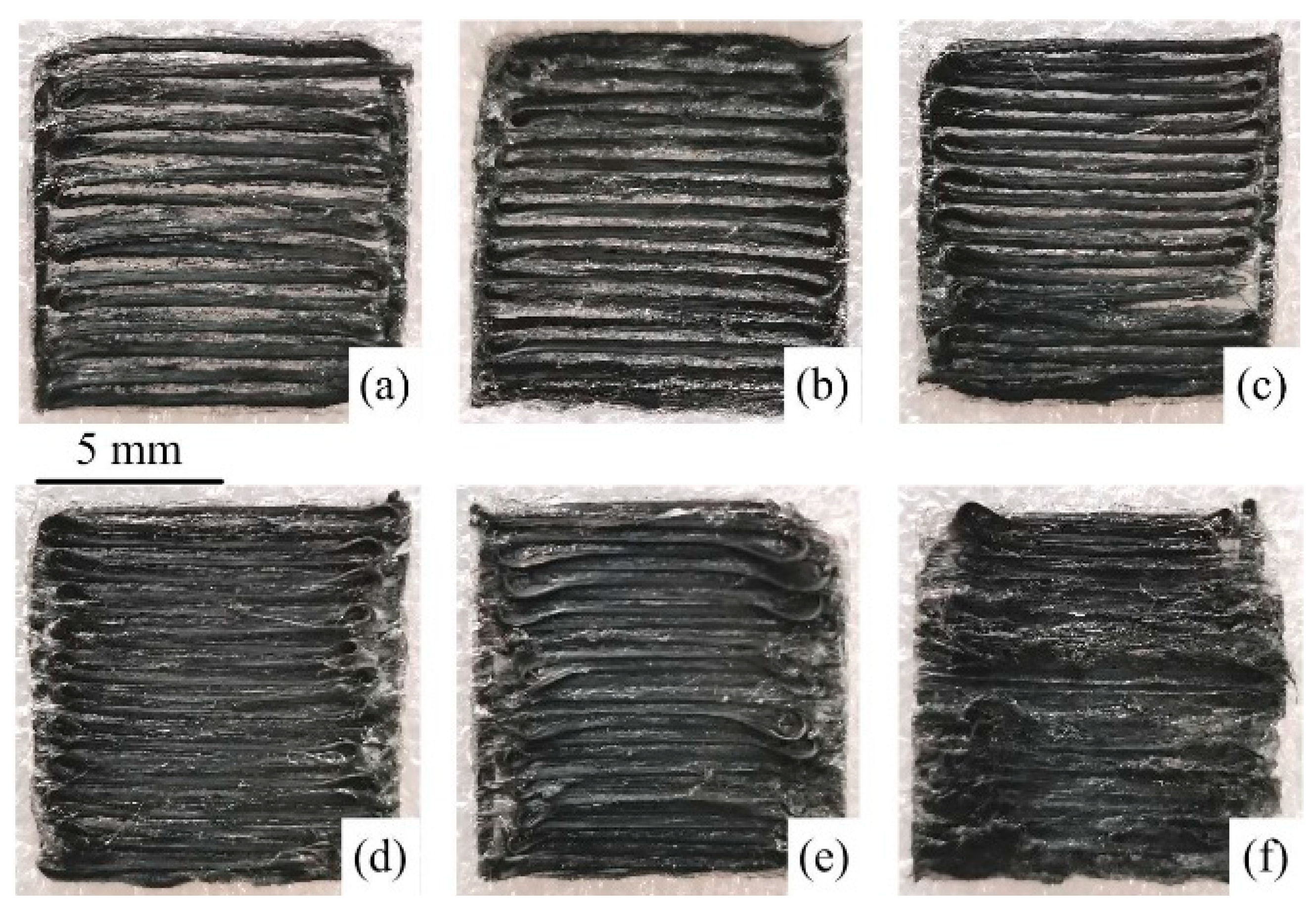
Figure 7 shows the surface morphologies of monolayer composites formed with different path overlap rates.
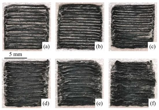
Figure 7.
Surface morphology of monolayer composites with different path overlap rates. (a) 10%; (b) 20%; (c) 30%; (d) 40%; (e) 50%; (f) 60%.It is obvious that when the path bonding rate was 10%, 20% and 30%, as shown in (a–c), an overlap between the two deposited single paths could not be perfectly achieved and there were obvious gaps between the paths; when the path bonding rate was 40%, as shown in (d), the gaps between the deposited paths were filled and the surface quality of the monolayer composite was also good; when the path bonding rate was 50% and 60%, as shown in (d,e), an excessive amount of composite material accumulated and formed bumps in the overlap area, and the movement of the nozzle formed scratches on the bumps, resulting in poor surface quality of the monolayer composite. Under the experimental conditions of this work, the optimal path lap ratio was 40%.
3.3. Experimental Results and Analysis of Solid Forming of Composite Materials
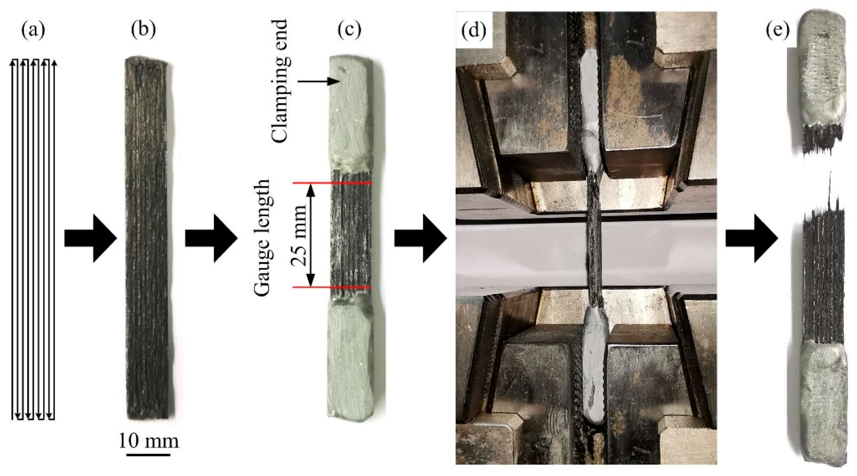
Figure 8 shows the forming path, preparation, and tensile test process used for the composite tensile test samples. The length and width of the tensile test samples were 85 and 10 mm, respectively. In order to prevent damage to the clamping part of the composite material caused by the testing machine fixture during the tensile process, and to ensure that the carbon fiber inside the entity can bear the tensile force uniformly, both ends of the prepared tensile specimen were coated with strong foundry glue, and the cured foundry glue was polished with sandpaper to make the two ends of the tensile specimen relatively flat. The gauge length of the sample was 25 mm. Finally, the tensile properties were tested. As shown in Figure 8e, an electronic universal testing machine effectively stretched the treated tensile sample entity, and the position where the specimen was broken was within the gauge length. Under the tensile force, the composite specimen sustained fracture and pull-out of the fibers. No continuous carbon fibers were found to be pulled out as complete clusters. The results show that the continuous carbon fiber in the composite sample was fully impregnated with PLA, and a good composite was formed between these two materials.

Figure 8.
Composite tensile specimen entity and its tensile process. (a) S-shaped forming path along the long side; (b) the original tensile sample; (c) both ends of the prepared tensile specimen were coated with strong foundry glue; (d) sample clamping and stretching; (e) the specimen after being pulled.
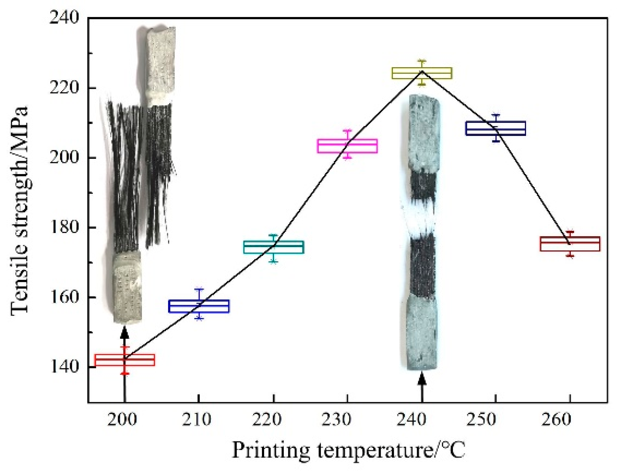
Figure 9 shows the results for the tensile properties of the three solid layers prepared at different printing temperatures with a set layer thickness of 0.7 mm, and photographs of the specimens after fracture. Figure 10 shows the microscopic morphology of the tensile specimen fractures at different magnifications; these were manufactured with print temperatures of either 210 °C or 240 °C.

Figure 9.
The test results of the tensile properties of the three-layer entities prepared at different printing temperatures and the photos of the specimens after pulling.

Figure 10.
(a,b) The micromorphology of tensile test specimen at different magnifications—210 °C; (c,d) the micromorphology of tensile test specimen at different magnifications—240 °C.
It can be seen that the tensile strength of the composite material is 2.2~3.5 times that of the single polylactic acid material (65 MPa). When the printing temperature was low (200~210 °C), due to the high viscosity and low fluidity of the re-melted PLA, it was impossible to achieve the secondary impregnation compound using continuous carbon fibers. The lower printing temperature also made it impossible to achieve sufficient diffusion of the molecular chains and effective interfacial fusion between the left and right deposition monolayers and the upper and lower deposition monolayers. Therefore, when the specimen was pulled, many continuous carbon fibers were pulled out directly from the composite specimen in complete clusters instead of fracturing. As shown in Figure 9, the interlayer interface fusion effect was poor after the specimen snapped, and as shown in Figure 10a, this eventually led to a lower tensile strength value of 142.3~157.6 MPa. As shown on the left of Figure 9, the interlayer interface of the specimen after pulling was poorly fused, and as shown in Figure 10a, this eventually led to a lower tensile strength value of 142.3~157.6 MPa. When the temperature of the PLA solution was increased from 200 °C to 240 °C, its non-Newtonian index increased from 0.1922 to 0.4262. Thus, we observed that, when the printing temperature was increased to 210~240 °C, the fluidity of PLA was enhanced, which promoted the impregnation of the PLA into the continuous carbon fibers, and improved the effective fusion between the deposited single channels and interlayers. Therefore, the tensile strength of the specimen also increased. When the printing temperature was 240 °C, the composite specimen sustained fracture and pull-out of the fibers under the tensile force. No continuous carbon fibers were found to be pulled out in complete clusters, as shown on the right side of Figure 9. After the specimen was snapped, we observed a better interfacial fusion between the specimen layers. As shown in Figure 10c, the resulting specimens had a maximum tensile strength value of 224.3 MPa, an increase of approximately 57.6% compared to the specimens printed at 200 °C.
When the printing temperature was between 240 and 260 °C, the tensile strength of the specimen decreased with an increase in printing temperature. At the printing temperature of 260 °C, the tensile strength value of the specimen decreased to 175.8 MPa, which was approximately 21.6% lower than that of the specimen printed at 240 °C. This is because when the temperature of the matrix material PLA approached its thermal decomposition temperature of 260 °C, decomposition of the macromolecular chains started to occur, which resulted in an overall decline in the mechanical properties of the composite specimen.
As can be seen in Figure 10a,c, many fibers were detached from the resin matrix. This is because in the printing process, due to the extrusion of the nozzle, the fibers of the composite material were more fully dispersed. At the same time, the distribution direction of some fibers was at a certain angle to the printing path. In the process of tensile testing, these fibers were not only subjected to axial tension, but also subjected to radial shear force, so it was easy for them to be detached from the matrix, and to fracture.
As can be seen in Figure 10b,d, the clusters of continuous carbon fibers were fully impregnated by PLA to form an excellent composite inside the composite specimens prepared at different printing temperatures. This was mainly attributed to the preparation of the prepreg filaments of the CCFRRMCs in the early stages.
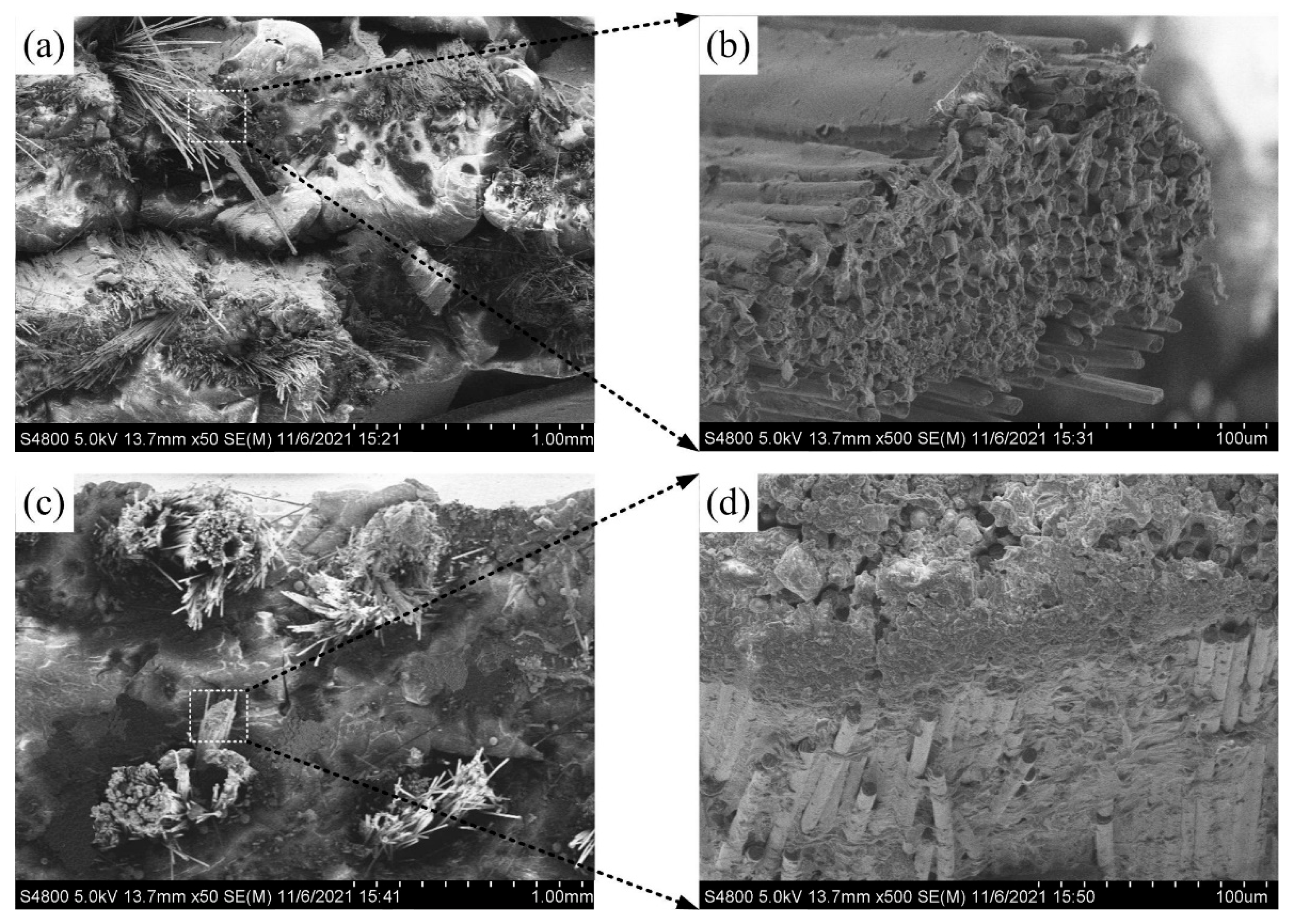
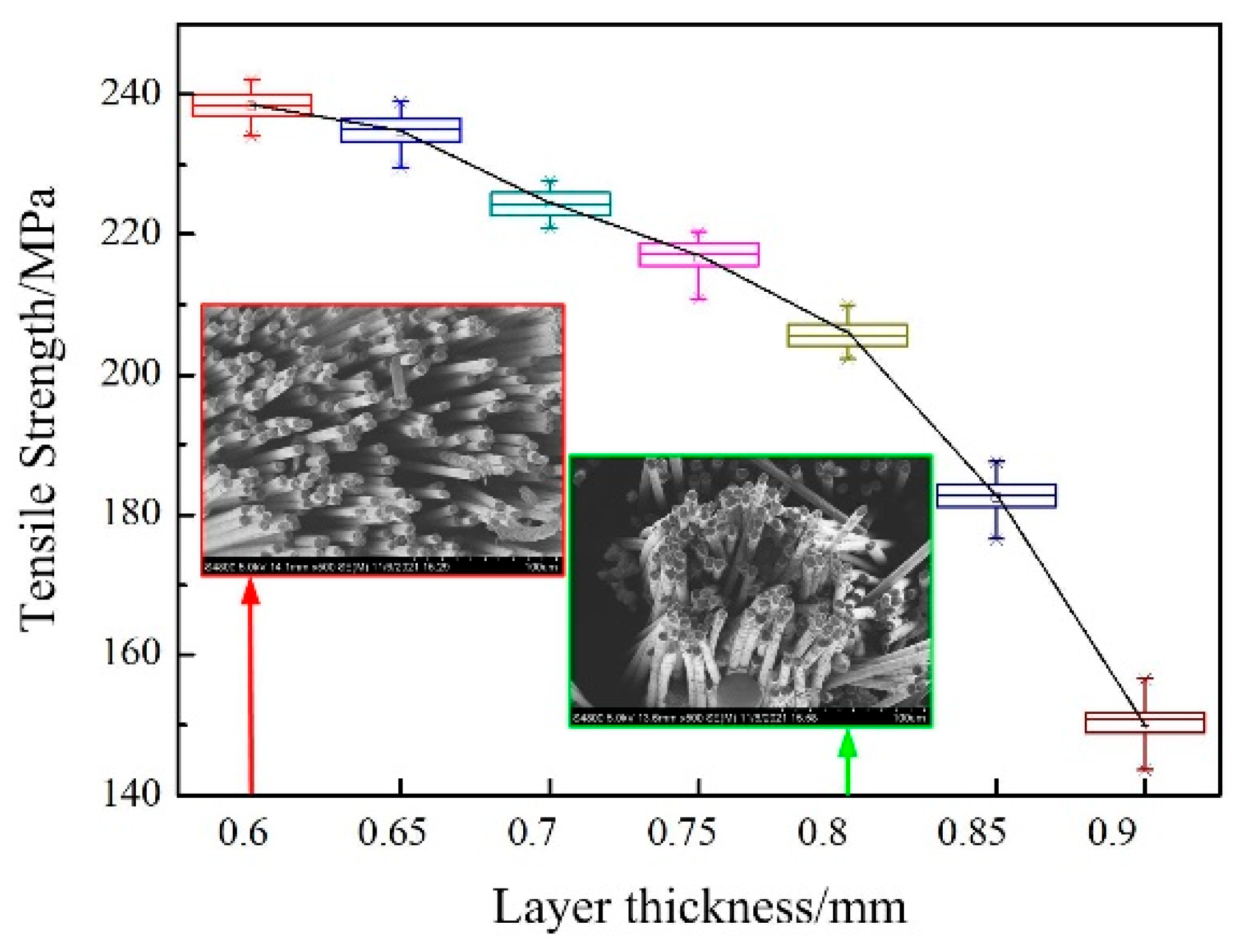
Figure 11 shows the results for the tensile properties of the three-layer solids prepared at different printing layer thicknesses with the printing temperature set at 240 °C, and the microscopic morphology of the carbon fiber distribution pattern at the fracture point of the specimen after pulling.
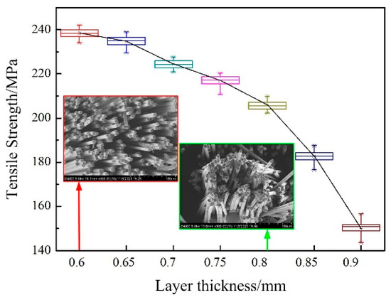
Figure 11.
The test results for the tensile properties of the three-layer entities prepared at different printing layer thicknesses and the microstructures of carbon fiber distribution at the fracture point of the sample. The red arrow points to the microstructure of the sample formed when the layer thickness is 0.6 mm. The green arrow points to the microstructure of the sample formed when the layer thickness is 0.8 mm.
Figure 12 shows the calculated theoretical values for fiber volume ratio of the three-layer entities prepared at different printing layer thicknesses.
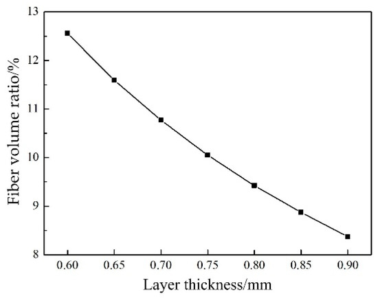
Figure 12.
The fiber volume ratios of the three-layer entities prepared at different printing layer thicknesses.
It can be seen that the tensile strength of the composite tensile test specimen decreased with an increase in printed layer thickness. When the printed layer thickness was increased from 0.6 mm to 0.9 mm, the tensile strength of the specimen decreased from 238.4 MPa to 150.8 MPa, which is a decrease of approximately 36.7%. When the printed layer thickness was smaller (0.6 mm), on the one hand, the fiber volume ratio in the sample was relatively large; on the other hand, the nozzle had a better compaction effect on the extruded composite, which not only facilitated the effective fusion between the deposition channels and the interlayer interface, but also promoted better dispersion and spreading of the clustered carbon fibers in the deposition channels. As shown in Figure 11, when the layer thickness was 0.6 mm, the micromorphology of carbon fiber distribution at the fracture point of sample was relatively ordered, thus obviously improving the tensile strength of the composite specimens. At the same time, the effective and uniform dispersion of fibers in the matrix was conducive to the more effective and uniform dispersion of the force to each fiber when the sample was subjected to radial load, so as to realize an increase in the shear strength of the sample. In contrast, when the print layer was thicker (0.8 mm), on the one hand, the fiber volume ratio in the sample decreased, while on the other hand, the nozzle could not compact the extruded composite, and the carbon fiber clusters in the specimen were not further dispersed and spread, so the mechanical properties of the composite specimen were poor. Under the experimental conditions of this work, the optimal layer thickness was 0.7 mm.
3.4. Experimental Results of Forming of Composite Cellular Load-Bearing Structural Parts
The honeycomb structure is the best topological structure covering two-dimensional planes; high in strength, light in weight, with good sound and heat insulation properties, and other excellent performance. Therefore, the current space shuttles, artificial satellites, and spacecraft adopt large numbers of honeycomb structures, and the shells of satellites are almost all made with honeycomb structures.
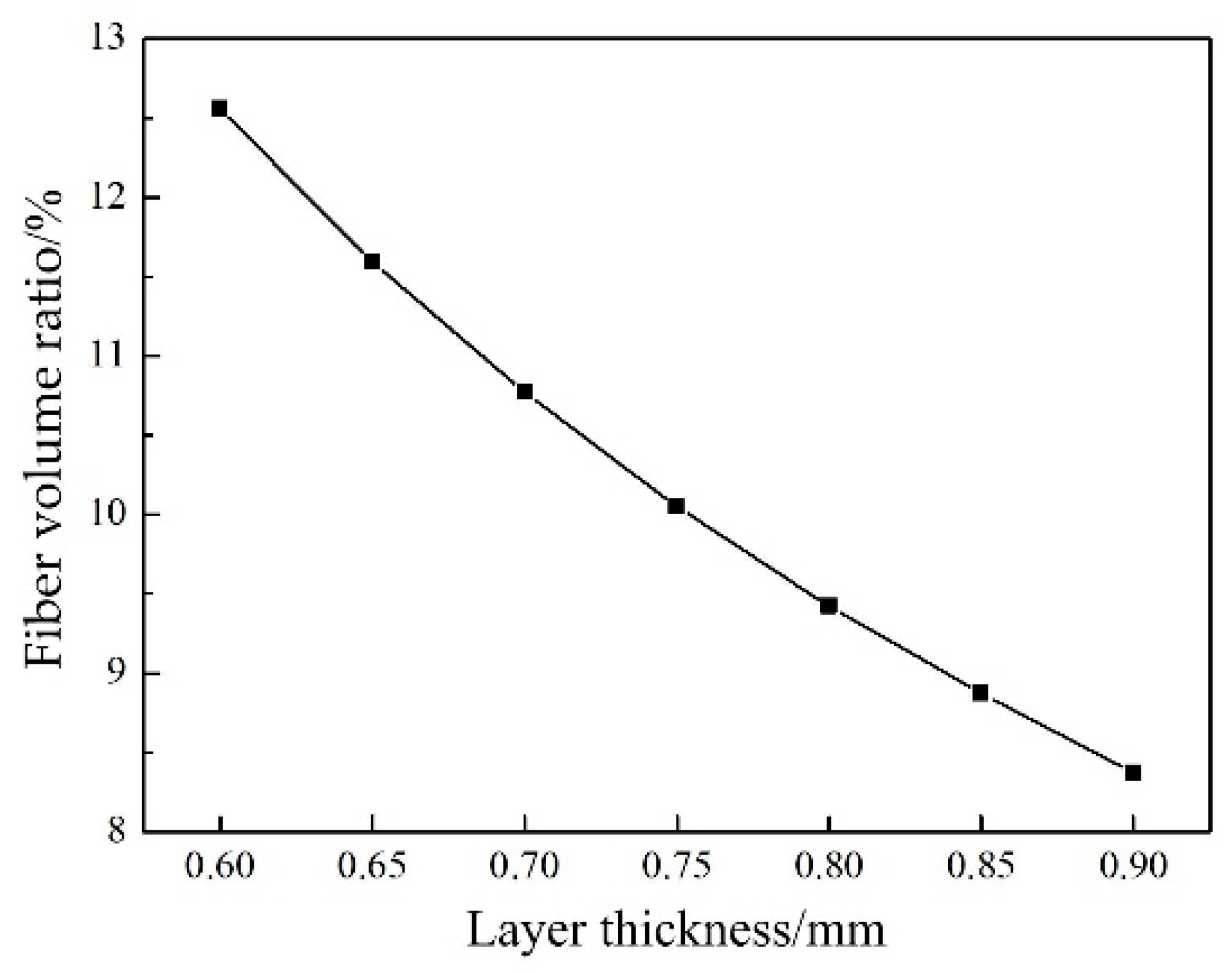
Continuous carbon fiber reinforced resin matrix composite has the advantages of light weight and high strength. Under the optimized parameter system, direct additive manufacturing of a composite honeycomb load-bearing structure was realized, as shown in Figure 13.

Figure 13.
Additive manufacturing of continuous carbon fiber reinforced resin matrix composite cellular load-bearing structure.
The boundary dimension of the structure was 77 mm × 67 mm × 17.5 mm, the wall thickness was 2 mm, the density was 1.28 × 10³ kg/m3, and the volume fraction of carbon fiber was approximately 7.7%.
4. Conclusions
An experimental study on a systematic additive manufacturing process was conducted using continuous carbon fiber reinforced PLA composite prepreg filaments, and we explored the effects of each process parameter on the composite forming properties. We can finally come to a number of noteworthy conclusions:
In order to obtain an excellent single channel forming quality, the wire feed speed needed to be set at the same value as the nozzle moving speed, and the speed should not be too large, to avoid unevenness of the deposition path edges. The optimal wire feeding speed and nozzle moving speed were 5 mm/s under the experimental conditions.
An appropriate setting of the path bonding rate could effectively fill gaps between adjacent deposited monolayers and avoid excessive accumulation of composites in the overlap region, thus obtaining monolayer composites with good surface quality. The optimal path bonding rate value was 40% under the experimental conditions.
The nozzle printing temperature had a significant effect on the macroscopic mechanical properties of the composites. An optimized printing temperature could promote the impregnation of the composite of molten matrix material and continuous carbon fiber, and the effective fusion between deposition channels and interlayer interfaces. Changing this parameter influenced the fracture mode of the composites under tensile forces, ultimately reflecting an improvement in mechanical properties. Under the experimental conditions, the optimal print temperature was 240 °C.
Nozzle height and print layer thickness had evident influence on forming accuracy, and on the mechanical properties of the composite materials. Nozzle height and print layer thickness were critical parameters for the forming process, and when set effectively, enabled avoidance of the phenomenon of poor path uniformity and of the carbon fiber being scratched, either due to abrasion by adjacent deposition in the single channel, or between the nozzle and the deposition layer. Furthermore, proper nozzle height and print layer thickness could realize adequate compaction of the nozzle to the composite material, facilitate the effective fusion between deposition channels and interlayer interfaces, and promote the dispersion and spread of clustered carbon fiber in the deposition channel. Finally, the mechanical properties of the sample were greatly improved. Under experimental conditions, the optimal nozzle height and print layer thickness was 0.7 mm.
Based on the optimized process parameters, direct additive manufacturing of honeycomb load-bearing structural parts with lightweight and high-strength composites could be achieved. The volume fraction of carbon fiber was approximately 7.7%, and the tensile strength reached 224.3 MPa.
Author Contributions
Writing—original draft preparation, L.Y.; formal analysis and data curation, D.Z.; writing—review and editing, G.J.; supervision and project administration, G.Y. All authors have read and agreed to the published version of the manuscript.
Funding
This research was funded by the Key Research and Development Program of Hebei Province, No. (21351002D); Hebei University of Science and Technology School of UAV R & D Special Project, No. (2019WRJ11).
Institutional Review Board Statement
Not applicable.
Informed Consent Statement
Not applicable.
Data Availability Statement
Not applicable.
Conflicts of Interest
The authors declare no conflict of interest.
References
- Lu, B.H.; Li, D.C. Development of the additive manufacturing (3D printing) technology. J. Mach. Build. Autom. 2013, 42, 1–4. [Google Scholar]
- Wei, Q.S.; Shi, Y.S. The Theory and Application of Additive Manufacturing; Science Press: Beijing, China, 2017; pp. 1–7. [Google Scholar]
- Yao, J.F.; Zhang, J.; Que, J.L. The Theory and Application of 3D Printing; Science Press: Beijing, China, 2017; pp. 15–37. [Google Scholar]
- Acanfora, V.; Corvino, C.; Saputo, S.; Sellitto, A.; Riccio, A. Application of an additive manufactured hybrid metal/composite shock absorber pan-el to a military seat ejection system. J. Appl. Sci. 2021, 11, 6473. [Google Scholar] [CrossRef]
- Acanfora, V.; Castaldo, R.; Riccio, A. On the effects of core microstructure on energy absorbing capabilities of sandwich panels intended for additive manufacturing. Materials 2022, 15, 1291. [Google Scholar] [CrossRef] [PubMed]
- Turner, B.N.; Strong, R.; Gold, S.A. A review of melt extrusion additive manufacturing processes: 1. Process design and modeling. Rapid Prototyp. J. 2014, 20, 192–204. [Google Scholar] [CrossRef]
- Turner, B.N.; Gold, S.A. A review of melt extrusion additive manufacturing processes: II. Materials, dimensional accuracy, and surface roughness. Rapid Prototyp. J. 2015, 21, 250–261. [Google Scholar] [CrossRef]
- Tekinalp, H.L.; Kunc, V.; Velez-Garcia, G.M.; Duty, C.E.; Love, L.J.; Naskar, A.K.; Blue, C.A.; Ozcan, S. Highly oriented carbon fiber-polymer composites via additive manufacturing. Compos. Sci. Technol. 2014, 105, 144–150. [Google Scholar] [CrossRef] [Green Version]
- Zhong, W.; Li, F.; Zhang, Z.; Song, L.; Li, Z. Short fiber reinforced composites for fused deposition modeling. Mater. Sci. Eng. A 2001, 301, 125–130. [Google Scholar] [CrossRef]
- Ning, F.; Cong, W.; Qiu, J.; Wei, J.; Wang, S. Additive manufacturing of carbon fiber reinforced thermoplastic composites using fused deposition modeling. Compos. Part B Eng. 2015, 80, 369–378. [Google Scholar] [CrossRef]
- Gray, R.W., IV; Baird, D.G.; Bohn, J.H. Thermoplastic composites reinforced with long fiber thermotropic liquid crystalline polymers for fused deposition modeling. Polym. Compos. 1998, 19, 383–394. [Google Scholar] [CrossRef]
- Gray, R.W., IV; Baird, D.G.; Bohn, J.H. Effects of processing conditions on short TLCP fiber reinforced FDM parts. Rapid Prototyp. J. 1998, 4, 14–25. [Google Scholar] [CrossRef]
- Luo, M.; Tian, X.; Shang, J.; Zhu, W.; Li, D.; Qin, Y. Impregnation and interlayer bonding behaviors of 3D-printing continuous carbon-fiber-reinforced poly-ether-ketone composites. Compos. Part A Appl. Sci. Manuf. 2019, 121, 130–138. [Google Scholar] [CrossRef]
- Yu, T.; Zhang, Z.; Song, S.; Bai, Y.; Wu, D. Tensile and flexural behaviors of additively manufactured continuous carbon fiber-reinforced polymer composites. Compos. Struct. 2019, 225, 111–147. [Google Scholar] [CrossRef]
- Wang, J.; Ge, X.; Liu, Y.; Qi, Z.; Li, L.; Sun, S.; Yang, Y. A review on theoretical modelling for shearing viscosities of continuous fibre-reinforced polymer composites. Rheol. Acta 2019, 58, 321–331. [Google Scholar] [CrossRef]
- He, Y.F.; Jiao, W.C.; Yang, F.; Liu, W.B.; Wang, R.G. The development of polymer composites forming process. Chin. J. Fiber Compos. 2011, 28, 7–13. [Google Scholar]
- Vaidya, U.K.; Chawla, K.K. Processing of fiber reinforced thermoplastic processing. Int. Mater. Rev. 2008, 53, 185–218. [Google Scholar] [CrossRef]
- Ma, Q.; Chen, Z.; Zheng, W.; Hu, H.F.; Xiao, J.Y. Resin transfer molding: A novel shaping process for composite materials. Mater. Sci. Eng. 2000, 18, 92–97. [Google Scholar]
- Kang, H.; Shan, Z.; Zang, Y.; Liu, F. Effect of yarn distortion on the mechanical properties of fiber-bar composites rein-forced by three-dimensional weaving. Appl. Compos. Mater. 2016, 23, 119–138. [Google Scholar] [CrossRef]
- Shan, Z.; Chen, S.; Zhang, Q.; Qiao, J.; Wu, X.; Zhan, L. Three-dimensional Woven forming technology and equipment. J. Compos. Mater. 2016, 50, 1587–1594. [Google Scholar] [CrossRef]
- Li, N.Y.; Li, Y.G.; Liu, S.T. Rapid prototyping of continuous carbon fiber reinforced polylactic acid composites by 3D printing. J. Mater. Processing Technol. 2016, 238, 218–225. [Google Scholar] [CrossRef]
- Tian, X.; Liu, T.; Yang, C.; Wang, Q.; Li, D. Interface and performance of 3D printed continuous carbon fiber reinforced PLA composites. Compos. Part A Appl. Sci. Manuf. 2016, 88, 198–205. [Google Scholar] [CrossRef]
- Wang, F.; Zheng, J.; Wang, G.; Jiang, D.; Ning, F. A novel printing strategy in additive manufacturing of continuous carbon fiber reinforced plastic composites. Manuf. Lett. 2021, 27, 72–77. [Google Scholar] [CrossRef]
- Wang, F.; Wang, G.; Ning, F.; Zhang, Z. Fiber-matrix impregnation behavior during additive manufacturing of continuous carbon fiber reinforced polylactic acid composites. Addit. Manuf. 2021, 37, 101661. [Google Scholar] [CrossRef]
- Liang, Y.; Liu, C.; Zhao, Q.; Lin, Z.; Han, Z.; Ren, L. Bionic design and 3D printing of continuous carbon fiber-reinforced polylactic acid composite with barbicel structure of eagle-owl feather. Materials 2021, 14, 3618. [Google Scholar] [CrossRef]


Publisher’s Note: MDPI stays neutral with regard to jurisdictional claims in published maps and institutional affiliations. |
© 2022 by the authors. Licensee MDPI, Basel, Switzerland. This article is an open access article distributed under the terms and conditions of the Creative Commons Attribution (CC BY) license (https://creativecommons.org/licenses/by/4.0/).