Article

In Situ Electrochemical Derivation of Sodium-Tin Alloy as Sodium-Ion Energy Storage Devices Anode with Overall Electrochemical Characteristics

College of Chemistry and Chemical Engineering, Xuchang University, Xuchang 461000, China
*
Author to whom correspondence should be addressed.
Crystals 2022, 12(5), 575; https://doi.org/10.3390/cryst12050575
Submission received: 8 March 2022 / Revised: 8 April 2022 / Accepted: 14 April 2022 / Published: 20 April 2022
(This article belongs to the Special Issue Emerging Low-Dimensional Materials)

Abstract

:
Inspired by the fermentation of multiple small bread embryos to form large bread embryos, in this study, the expansion of tin foil inlaid with sodium rings in the process of repeated sodium inlaid and removal was utilized to maximum extent to realize the formation of sodium-tin alloy anode and the improvement of sodium storage characteristics. The special design of Sn foil inlaid with Na ring realized the in-situ electrochemical formation of fluffy porous sodium-tin alloy, effectively alleviated the volume expansion and shrinkage of non-electrochemical active Sn metal, and inhibited the generation of sodium dendrites. The abundance of sodium ions provided by the Na metal ring compensated for the active sodium components consumed during the repeated formation of SEI. When sodium-tin alloy in situ derived by Sn foil inlaid with Na ring was used as negative electrodes matched with SCDC and Na0.91MnO2 hexagonal tablets (NMO HTs) positive electrodes, the as-assembled sodium-ion energy storage devices present high specific capacity and excellent cycle stability.

1. Introduction

With the aggravation of the greenhouse effect and the increase of people’s demand for clean energy, lithium-ion batteries (LIBs), which are scarce in resources, will not be able to meet the demand for large-scale energy storage due to the price rise and market competition [1,2,3]. Among many alternatives, sodium ion batteries/capacitors (SIBs/SICs) with similar working principle to LIBs/LICs, suitable Stoke radius (solvation radius, that of Na+ is 4.6 Å), rich sodium resources, aluminum as a collector, low cost and other advantages have attracted extensive attention of researchers [4]. However, the larger radius of Na+ (1.02 Å) than that of Li+ (0.76 Å) makes it difficult to insert Na+ into the interlayer of commercial graphite, which results the low theoretical capacity (35 mA h g−1) and energy density of SIBs [5,6]. Although transition metal oxides/sulfides/selenides based on conversion-reaction mechanism can deliver fascinating sodium ion storage capacity, their realistic application is still limited because of the slow dynamics and inadequate cyclic stability [7,8,9]. Therefore, the exploration of anodes for rapid storage of Na+ ions is still an important research area.
Sn, Sb, Te, Bi, Si and Se metal and their alloys with good electrical conductivity and high specific capacity were considered as rapid sodium ion storage anodes [10,11,12,13,14,15,16,17,18,19]. However, the large volume expansion of them often leads to capacity attenuation and insufficient cycle stability of SIBs during repeated charge and discharge [20,21,22,23,24,25]. Aiming at the volume expansion mentioned, many strategies such as heterogeneous element doping, carbon coating were taken. Although these strategies can effectively alleviate the problem of large-rate discharge, the electrochemical activity Na ions consumed by the repeated formation of SEI film still cannot be instantaneously replenish during the process of charge and discharge, and their specific capacity and cyclic stability are still far from practical application [26,27,28,29,30]. Therefore, based on rational utilization of expansion of metal Sn during charge and discharge, this study purposefully designed a Sn foil inlaid Na ring structure to in situ achieve electrochemical derivatization of sodium-tin alloy anode. Subsequently, the sodium-tin alloy anodes derived by tin foil inlaid sodium ring were matched with the positive electrode of sodium citrate derived carbon (SCDC) and NMO HTs respectively to assemble button cells. The result demonstrated that these cells exhibited the high mass specific capacity and excellent cyclic longevity, which is about 100 mAh g−1 for SCDC after 10,000 cycles and 60 mAh g−1 for NMO HTs after 8400 cycles.

2. Materials and Methods

2.1. Materials and Chemicals

All the reagents used were manually ground for several minutes without further purification.

2.2. Preparation of Na0.91MnO2 Hexagonal Tablets

Na0.91MnO2 hexagonal tablets were prepared as follows: MnO2 and anhydrous Na2CO3 with different molar ratio of 1:0.53 were separately added to a certain amount of deionized water, and subsequently were stirred and evaporated to dryness on the heated magnetic stirrer, then the homogenous mixture of MnO2 and anhydrous Na2CO3 were obtained. Finally, the temperature of the mixture was procedurally raised to 350 °C at a rate of 3 °C per minute for 6 h in air, then to 850 °C at the same rate for 12 h in air. A kind of smoke grey powder was obtained.

2.3. Instrumentation and Sample Analysis

The morphologies and microstructure of the NMO HTs and sodium-tin alloy prepared by electrochemical in-situ method was detected by Field Emission Scanning Electronic Microscopy (FESEM, JSM-6701F). Transmission electron microscopy (TEM) and high-resolution TEM (HRTEM) were performed with HITACHI-H7650 and JEM-2100F (JEOL) instruments, and the kinetic energy of electrons was 200 kV. For SEM detection of sodium-tin alloy, it was particularly worth mentioning that the button battery after circulation was disassembled in the glove box with water and oxygen content less than 0.1 ppm, next the sodium-tin alloy was taken out. After washing with DMC solution, the sodium-tin alloy was placed in the glove box overnight to drying, and cut off the parts with scissors. Subsequently, one of the cut parts was paste on the conductive adhesive of the sample stand, and transferred into the test box filled with high purity argon gas. The entire transfer process was carried out in the high purity argon gas.

2.4. Electrochemical Measurements

The electrochemical tests were performed at constant temperature of 25 °C using double-electrode 2032-type coin cells with sodium disc or tin foil disc and sodium rings as the counter electrodes. For fabrication of SCDC and NMO HTs cathodes, 70 wt% of active material, 20 wt% of carbon black (Super-P) and 10 wt% of polyvinylidenefluoride (PVDF) in methyl-2-pyrrolidone (NMP) were well mixed and then coated on the Al foil which served as a current collector. After heated at 90 °C for 12 h under vacuum, the sheet was pressed and punched into 14 mm diameter electrodes with a mass loading of 1.0–2.0 mg. For electrochemical in situ fabrication of sodium-tin alloy anode: after inserting 2 mm sodium ring around the 14 mm tin foil, sodium-tin alloy is formed during repeated charge and discharge. The electrolyte used in our work was 1 M NaClO4 in a 1:1:1 (v/v/v) mixture of ethylene carbonate (EC), diethyl carbonate (DMC) and ethyl methyl carbonate (EMC), which was added 2% (mass ratio) fluoroethylene carbonate (FEC). The cell assembly was carried out in an argon-filled glove box with both the moisture and the oxygen content below 0.1 ppm. The CV tests were conducted with scan rates from 0.1 to 5 mV s−1. Electrical impedance spectroscopy (EIS) studies were carried out using PGSTAT302N (Metrohm Co., Herisau, Switzerland) in the frequency range from 0.1 MHz to 0.05 Hz with an amplitude of 5 mV. Galvanostatic charge/discharge and cyclic stability characteristic were collected between 2.0 V and 4.0 V on a Neware BTS-5V10 mA (New well electronic Technology Co., LTD, Guangzhou, China).

3. Results and Discussions

As Figure 1 shown, inspired by the crowded arrangement and fermentation of multiple small embryos into a large embryo, this study aims to design the tin foil inlaid sodium ring structure to realize the in-situ electrochemical formation of sodium-tin alloy. The unique structure can alleviate the volume expansion and shrinkage of non-electrochemical active metal Sn and inhibit the generation of sodium dendrites. The embedded sodium ring can provide sufficient electrochemical activity Na+ for the system, which can compensate for sodium ions consumed by the repeated formation of SEI during the charge and discharge process of anode and cathode materials. To avoid the influence of positive electrode reaction on the evolution process of sodium-tin alloy, the mature SCDC was selected as the positive electrode to assemble coin cells.
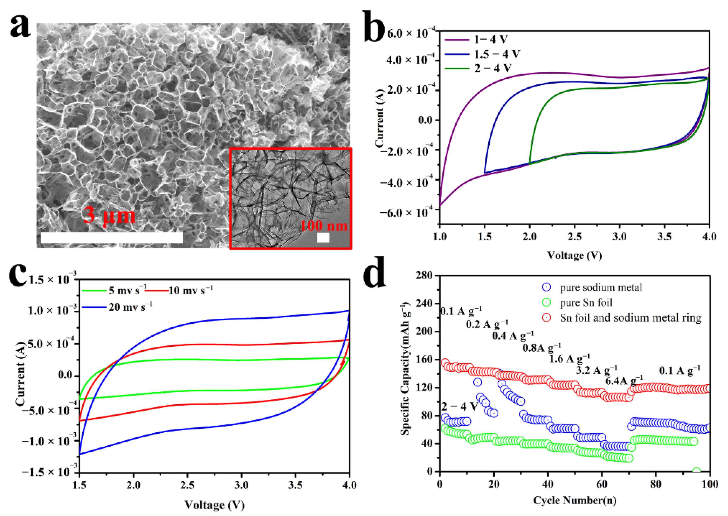
Firstly, the morphology of SCDC was tested by SEM and TEM. As Figure 2a and inset 2a shown, SCDC presents a comb structure. Raman result present inset Figure 2a demonstrated that the ratio of D/G was 2.57, which indicated that SCDC was rich in defects. The existence of these defects is beneficial to improve the storage of sodium ions. To explore the optimum operating voltage range of coin cell with sodium tin alloy as anode and SCDC as cathode. Cyclic voltammetry of these cells was determined in different voltage range. As shown in Figure 2a, the polarization of cyclic voltammetry curves for SCDC positive is significant at 1.0 V–4.0 V compared with at 1.5–4.0 V and 2.0–4.0 V. Therefore, considering the influence of the operating voltage range on mass specific capacity of SCDC, 1.5 V–4.0 V is selected as the charge-discharge voltage range. As a comparison, the electrochemical properties of pure sodium and tin foil anode were also tested, as exhibited in Figure 2c. The results show that when sodium-tin alloy prepared by in situ electrochemical epitaxy is used as anode, SCDC exhibits the highest gradient mass specific capacity compared with that of pure Sn foil and pure Na metal disc as anode, just as shown in Figure 2d. It should be noted that the specific capacity of the pure sodium anode for the first 20 laps was lower than that of the sodium tin alloy anode because the voltage range for the first 10 laps is 2–4 V.
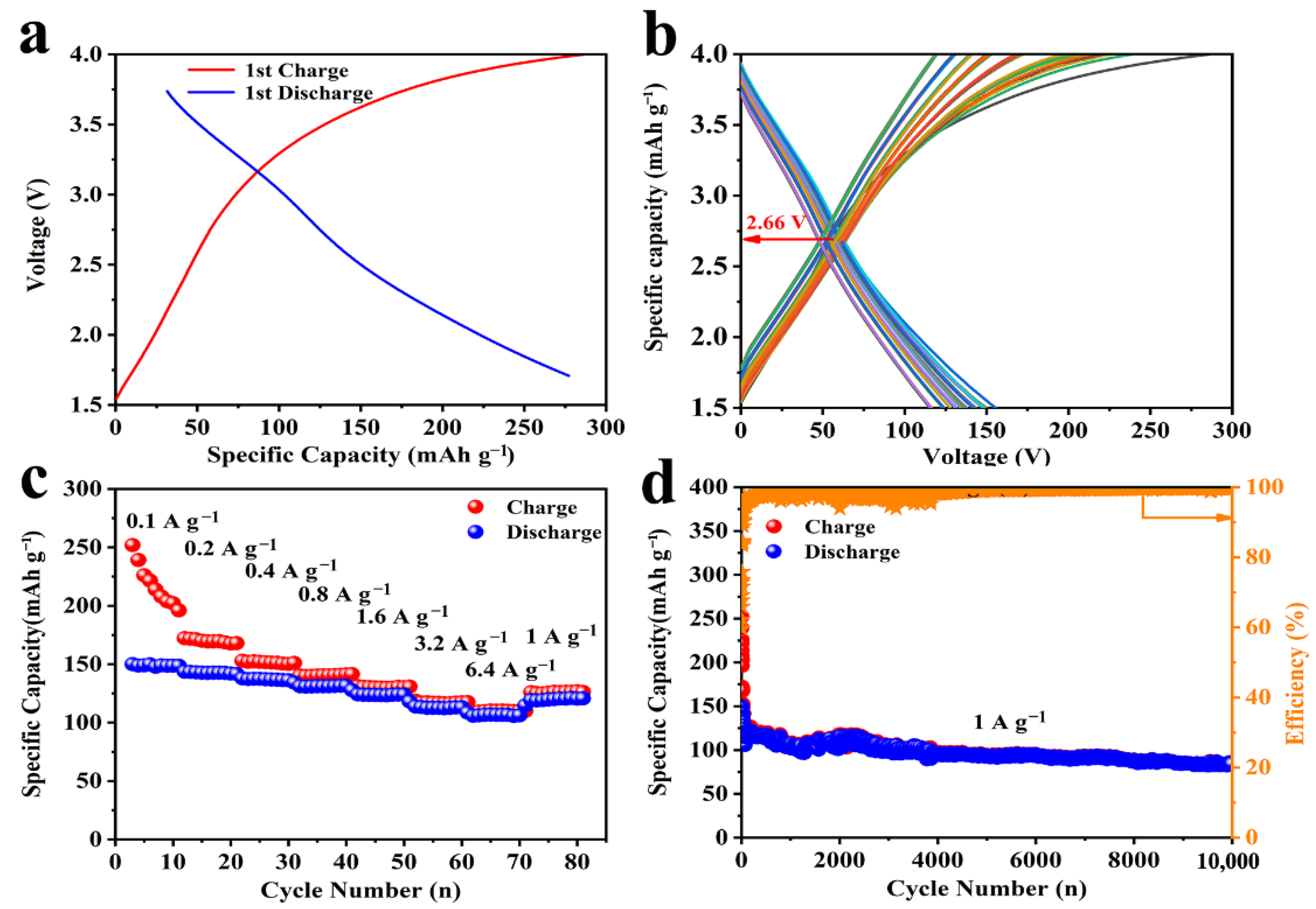
The gradient characteristic (Figure 3a–c) and cyclic stability (Figure 3b–d) of SCDC vs. sodium-tin alloy anode were also determined. As presented in Figure 3a,b, SCDC exhibits the first mass specific capapcity of 280 mAh g−1, and considerable mid-value voltage of 2.66 V. Figure 3c indicates that SCDC exhibited high gradient capacities of 250 mAh g−1, 170 mAh g−1, 155 mAh g−1, 148 mAh g−1, 145 mAh g−1, 125 mAh g−1 and 120 mAh g−1 at the current density of 0.1 A g1, 0.2 A g1, 0.4 A g1, 0.8 A g1, 1.6 A g1, 3.2 A g1 and 6.4 A g1, respectively. Along with high capacity of 100 mAh g−1 and ultra-long cyclic life of 10,000 cycles at 1.0 A g1, sodium-tin alloy in situ electrochemically derived will possibly be a candidate anode of devices with high mass specific capacity and excellent cyclic longevity. It basically attributes to the multi-hole and irregular surface of sodium-tin alloy, which can afford more storage space for electrochemically active Na+ ions. While these electrochemical activity Na ions can instantaneously complement those consumed during the repeated formation of SEI film.
Considering the universal application of the sodium-tin alloy in situ electrochemically derived, the coin cells were also assembled, in which sodium-tin alloy in situ electrochemically derived by Sn foil (13 mm) inlaid with Na ring (1 mm) was negative, and Na0.91MnO2 hexagonal tablets (just as XRD demonstrated inset Figure 4b) was the counter electrode. The electrochemical performance of as-assembled coin cells presents that NMO HTs vs. sodium-tin alloy anode displays a high first-lap specific capacity of 140 mAh g−1 at 0.1 A g−1 current density, and it remains nearly 90 mAh g−1 after 570 cycles, as Figure 4a shown. The gradient capacity and the cyclic stability for NMO HTs cathode vs. sodium-tin alloy anode was also collected, as shown in Figure 4b,c. In the gradient range from 0.1 to 1.6 A g−1 for 10 laps at each stage, the discharge capacity of the coin cell with NMO HTs as cathode and sodium-tin alloy as anode keeps 96 mAh g−1 at current density of 0.1 A g−1 after 10 laps. When the current density stepwise increased to 0.2, 0.5, 1, and 2 A g−1, the corresponding specific capacities present 85, 78, 67, and 55 mAh g−1, respectively. When the current density turns back to 0.1 A g−1, the specific capacity still maintains 140 mAh g−1 and ultimately holds 89 mAh g−1. However, it cannot be neglected that the first coulombic efficiencies of these batteries are all lower than 70% and gradually increase to 100% as the charge-discharge cycle continues, which dominantly comes down to the concentration polarization caused by the difference of sodium ion concentration on the surface of metal tin anode at the initial stage of charge and discharge. But with the progress of the charging and discharging cycle, this polarization gradually weakens, so that NMO HTs still maintains nearly 60 mAh g−1 specific capacity after 8400 cycles at 1 A g−1 directly achieved after gradient cycles, as Figure 4c,d demonstrated. The excellent cyclic stability principally attributes to the improvement of Na+ ion transport rate caused by thin lamellar of NMO HTs cathode and the exceptional conductivity and stability of sodium-tin alloy counter electrode in situ electrochemically derived by Sn foil (13 mm) inlaid with Na ring (1 mm).
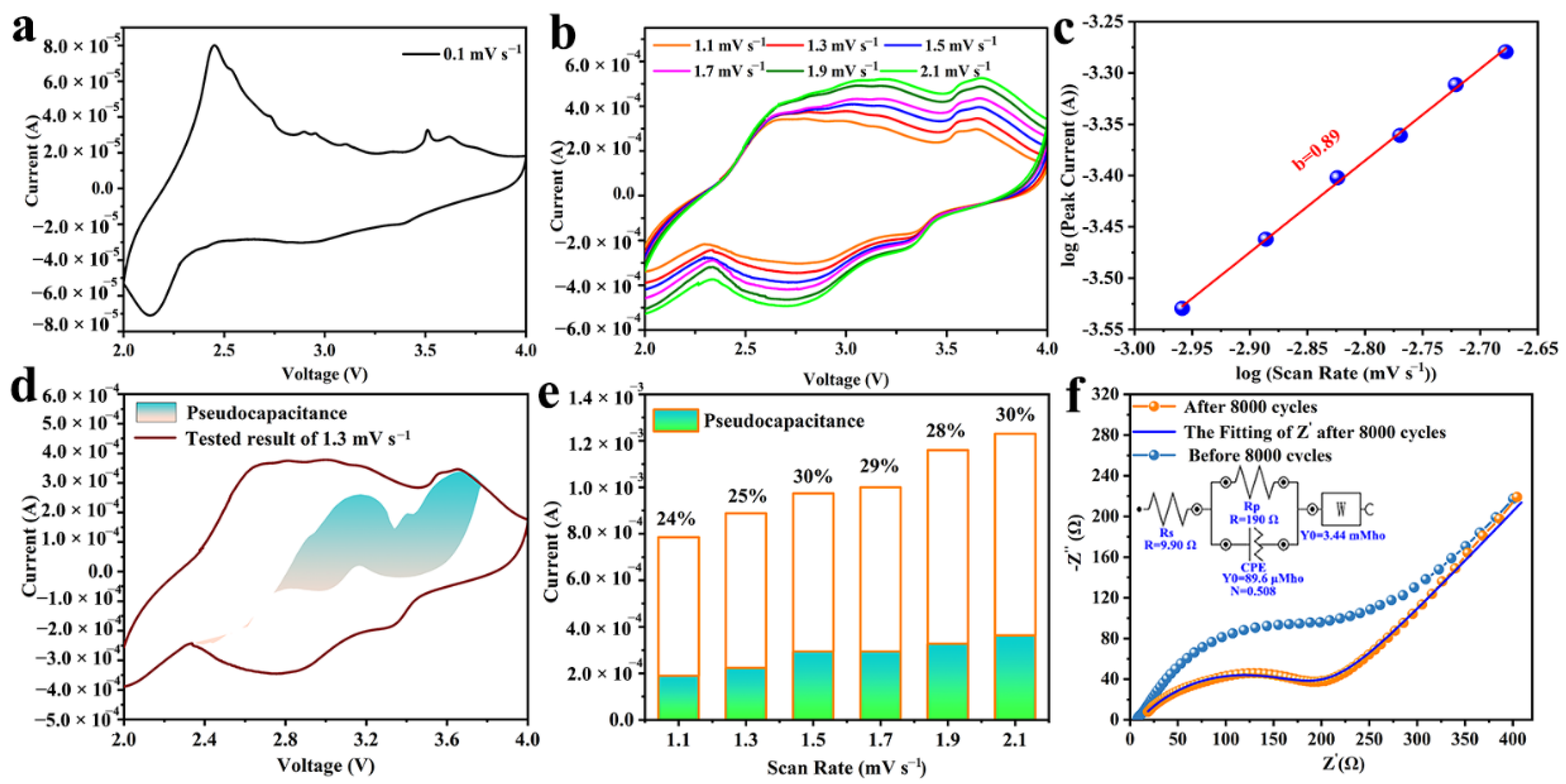
To further explore the potential reasons for the excellent electrochemical performance of NMO HTs, we performed CV detection and fitting. Figure 5a illustrates the original CV curves at different scan rates of NMO HTs positive vs. sodium-tin alloy negative in situ electrochemically derived, it is found that there are one distinct reduction peak at 2.13 V and two oxidation peaks at 2.45 V and 3.6 V, respectively. CV curves scanned at different rates shown in Figure 5b are overlapped and almost the same shape, which further confirms the excellent reversibility of the above coin cell. Furthermore, the capacitive/battery contribution to the total charge storage of NMO HTs positive vs. sodium-tin alloy negative electrochemically derived was also quantified through the method of charging storage distinction according to the accurate and efficient analysis method of charge storage mechanism and pseudo contribution in cyclic voltammetry curve developed by Dunn et al. Accordingly, the total current at a fixed potential can be expressed as the combination of two parts of pseudocapacitive (k1ν) and diffusion-controlled capacity (k2ν0.5) [31,32].
i(V) = k1ν + k2ν0.5
For further mathematical treatment, Equation (1) slightly transfers to
i(V)/ν0.5 = k1ν0.5 + k2
On account of the linear fitting (Figure 5c) for logarithm of voltage to logarithm of currents at each potential, the coefficients k1 and k2 can be determined, and the k1ν and k2ν0.5 were calculated. Then the pseudo capacitive (k1ν) and diffusion control contribution (k2ν0.5) are distinguished [33,34,35]. As demonstrated in Figure 5d, the shaded regions stand for the contribution from charge controlled by the capacitive, while the blank areas represent the diffusion control contribution. The results demonstrate that the capacitive controlled charge occupied about 25% of the entire charge storage capacity of 1.3 mV s−1. However, it suddenly increases to 30% at 1.5 mV s−1, which is due to the coin cell holds for a whole night between 1.3 mV s−1 and 1.5 mV s−1 test. In particular, the capacitance charge ratio has turned slowly upward from 1.7–2.1 mV s−1 (Figure 5e). The above results indicate although the proportion of NMO HTs pseudocapacitive charge is less than 30% of the total charge, the dynamic defects of solid-state diffusion can still be effectively alleviated. This is also demonstrated by electrochemical impedance spectroscopy (EIS, Figure 5f). As Figure 5f indicated, the Nyquist plot in high frequency region is respectively contributed by physical impedance of device and interface impedance resistances between NMO HTs electrode and electrolyte, while the low-frequency impedance derived from the diffusion of Na ions, which is consistent with the equivalent current diagram inset Figure 5f.
In order to verify the in-situ electrochemical formation of sodium-tin alloy and compare the differences between sodium-tin alloy derived by (a) pure Sn foil and (b) Sn foil inlaid with Na metal ring. the according image were observed after repeated charge-discharge. As Figure 6a–c presented, the surface of sodium-tin alloy derived by Sn foil inlaid with Na metal ring become multi-hole and irregular compared with that of sodium-tin alloy derived by pure Sn foil. This unique structure is contributed to affording more storage space for electrochemically active Na+ ions. Simultaneously, Na ions consumed by the repeated formation of SEI film can be instantaneously complement during the process of charge and discharge. Together with the uniform distribution of Na and Sn elements (Figure 6d,e), sodium-tin alloy in situ derived by Sn foil inlaid with Na ring was used as negative, and matched with SCDC and NMO HTs as positive present high specific capacity and remarkable cyclic stability. This provides a new avenue for the assembly of sodium storage energy devices with excellent electrochemical performance. The EDS (Figure 6f) of sodium-tin alloy further verified that the molar ratio of Na and Sn elements is 19.4/1, which is far higher than maximum theoretical mole ratio 15/4 for sodium embedding. It is indicated that in addition to contributing to the formation of Na15Sn4 alloy (Na15Sn4 ⇔15Na++ 4Sn +15e), Na metal ring also compensated for sodium ions consumed by the repeated formation of SEI in reaction system during charge and discharge.

4. Conclusions

To summery, the sodium-tin alloy was successfully in situ electrochemically derived through a simple and practicable design of Sn foil (13 mm) inlaid with Na ring (1 mm). In view of the distinctive design, the expansion of tin foil during the repeated sodium ions inlaid and removal was utilized to maximum extent, the formation of sodium-tin alloy anode and the improvement of sodium storage characteristics were realized, Na ions consumed by the repeated formation of SEI film were instantaneously complement. When the in-situ as-derived sodium-tin alloy was used as anode, SCDC as cathode, the as-assembled sodium ion capacitors exhibited about 100 mAh g−1 high specific capacity after 10,000 cycles; while when NMO HTs as cathode, the as-assembled sodium ion batteries exhibited favorable pseudocapacitive behavior and about 80 mAh g−1 specific capacity after 8400 cycles. The above results demonstrated that the strategy of in-situ electrochemical derivation can provide a reference for sodium ion energy storage devices with overall electrochemical characteristics.

Author Contributions

Formal analysis, writing—original draft preparation, writing—review and editing, L.W.; resources, funding acquisition, L.N.; data curation, visualization, W.L.; investigation, B.S., L.S. and Q.Z.; project administration, S.G. All authors have read and agreed to the published version of the manuscript.

Funding

This work was supported by the Nature Science Foundations of Henan Province (202300410349), High Education Teaching Reform Research and Practice Project of Henan Province (2021SJGLX227Y, Postgraduate Education), Scientific Research Project of Xuchang University (2021YB001).

Institutional Review Board Statement

Not applicable.

Informed Consent Statement

Not applicable.

Data Availability Statement

The data presented in this study are available on request from the corresponding author.

Conflicts of Interest

The authors declare no conflict of interest.

References

  1. Sun, M.; Wang, Z.; Ni, J.; Li, L. Dual-doped hematite nanorod arrays on carbon cloth as a robust and flexible sodium anode. Adv. Funct. Mater. 2020, 30, 1910043. [Google Scholar] [CrossRef]
  2. Yabuuchi, N.; Kubota, K.; Dahbi, M.; Komaba, S. Research development on sodium-ion batteries. Chem. Rev. 2014, 114, 11636–11682. [Google Scholar] [CrossRef] [PubMed]
  3. Wang, G.; Yu, M.; Feng, X. Carbon materials for ion-intercalation involved rechargeable battery technologies. Chem. Soc. Rev. 2021, 50, 2388–2443. [Google Scholar] [CrossRef] [PubMed]
  4. Usiskin, R.; Lu, Y.; Popovic, J.; Law, M.; Balaya, P.; Hu, Y.S.; Maier, J. Fundamentals, status and promise of sodium-based batteries. Na. Rev. Mater. 2021, 6, 1020–1035. [Google Scholar] [CrossRef]
  5. Cao, Y.; Xiao, L.; Sushko, M.L.; Wang, W.; Schwenzer, B.; Xiao, J.; Nie, Z.; Saraf, L.V.; Yang, Z.; Liu, J. Sodium ion insertion in hollow carbon nanowires for battery applications. Nano Lett. 2012, 12, 3783–3787. [Google Scholar] [CrossRef]
  6. Chen, Y.; Li, X.; Park, K.; Lu, W.; Wang, C.; Xue, W.; Yang, F.; Zhou, J.; Suo, L.; Lin, T. Nitrogen-doped carbon for sodium-ion battery anode by self-etching and graphitization of bimetallic MOF-based composite. Chem 2017, 3, 152–163. [Google Scholar] [CrossRef] [Green Version]
  7. Zhang, B.; Kang, F.; Tarascon, J.M.; Kim, J.K. Recent advances in electrospun carbon nanofibers and their application in electrochemical energy storage. Prog. Mater. Sci. 2016, 76, 319–380. [Google Scholar] [CrossRef]
  8. Wenzel, S.; Hara, T.; Janek, J.; Adelhelm, P. Room-temperature sodium-ion batteries: Improving the rate capability of carbon anode materials by templating strategies. Energy Env. Sci. 2011, 4, 3342–3345. [Google Scholar] [CrossRef] [Green Version]
  9. Li, Z.; Ding, J.; Mitlin, D. Tin and tin compounds for sodium ion battery anodes: Phase transformations and performance. Acc. Chem. Res. 2015, 48, 1657–1665. [Google Scholar] [CrossRef]
  10. Jing, W.T.; Yang, C.C.; Jiang, Q. Recent progress on metallic Sn- and Sb-based anodes for sodium-ion batteries. J. Mater. Chem. A 2020, 8, 2913–2933. [Google Scholar] [CrossRef]
  11. Kim, C.; Kim, H.; Sadan, M.K.; Jeon, M.; Cho, G.; Ahn, J.; Kim, K.; Cho, K.; Ahn, H. Development and evaluation of Sn foil anode for sodium-ion batteries. Small 2021, 17, 2102618. [Google Scholar] [CrossRef]
  12. Song, M.; Wang, C.; Du, D.; Li, F.; Chen, J. A high-energy-density sodium-ion full battery based on tin anode. Sci. China Chem. 2019, 62, 616–621. [Google Scholar] [CrossRef]
  13. Chen, L.; He, X.; Chen, H.; Huang, S.; Wei, M. N-Doped carbon encapsulating Bi nanoparticles derived from metal-organic frameworks for high-performance sodium-ion batteries. J. Mater. Chem. A 2021, 9, 22048–22055. [Google Scholar] [CrossRef]
  14. Cheng, D.; Yang, L.; Hu, R.; Liu, J.; Che, R.; Cui, J.; Wu, Y.; Chen, W.; Huang, J.; Zhu, M. Sn-C and Se-C Co-bonding SnSe/few-layered graphene micro-nano structure: Route to a densely compacted and durable anode for lithium/sodium-Ion Batteries. ACS Appl. Mater. Interfaces 2019, 11, 36685–36696. [Google Scholar] [CrossRef]
  15. Cheng, Y.; Huang, J.; Li, R.; Xu, Z.; Cao, L.; Ouyang, H.; Li, J.; Qi, H.; Wang, C. Enhanced cycling performances of hollow Sn compared to solid Sn in Na-ion battery. Electrochim. Acta 2015, 180, 227–233. [Google Scholar] [CrossRef]
  16. Lin, Y.M.; Abel, P.R.; Gupta, A.; Goodenough, J.B.; Heller, A.; Mullins, C.B. Sn-Cu nanocomposite anodes for rechargeable sodium-ion batteries. ACS Appl. Mater. Interfaces 2013, 5, 8273–8277. [Google Scholar] [CrossRef]
  17. Liu, J.; Yu, L.; Wu, C.; Wen, Y.; Yin, K.; Chiang, F.K.; Hu, R.; Liu, J.; Sun, L.; Gu, L. New nanoconfined galvanic replacement synthesis of hollow Sb@C yolk-shell spheres constituting a stable anode for high-rate Li/Na-ion batteries. Nano Lett. 2017, 17, 2034–2042. [Google Scholar] [CrossRef]
  18. Liu, S.; Luo, Z.; Guo, J.; Pan, A.; Cai, Z.; Liang, S. Bismuth nanosheets grown on carbon fiber cloth as advanced binder-free anode for sodium-ion batteries. Electrochem. Commun. 2017, 81, 10–13. [Google Scholar] [CrossRef]
  19. Lu, Y.; Zhou, P.; Lei, K.; Zhao, Q.; Tao, Z.; Chen, J. Selenium phosphide (Se4P4) as a new and promising anode material for sodium-ion batteries. Adv. Energy Mater. 2017, 7, 1601973. [Google Scholar] [CrossRef]
  20. Luo, B.; Qiu, T.; Ye, D.; Wang, L.; Zhi, L. Tin nanoparticles encapsulated in graphene backboned carbonaceous foams as high-performance anodes for lithium-ion and sodium-ion storage. Nano Energy 2016, 22, 232–240. [Google Scholar] [CrossRef]
  21. Mao, J.; Fan, X.; Luo, C.; Wang, C. Building self-healing alloy architecture for stable sodium-ion battery anodes: A case study of tin anode materials. ACS Appl. Mater. Interfaces 2016, 8, 7. [Google Scholar] [CrossRef]
  22. Nagulapati, V.M.; Lee, J.H.; Kim, H.S.; Oh, J.; Kim, I.T.; Hur, J.; Lee, S.G. Novel hybrid binder mixture tailored to enhance the electrochemical performance of SbTe bi-metallic anode for sodium ion batteries. J. Electroanal. Chem. 2020, 865, 114160. [Google Scholar] [CrossRef]
  23. Oh, J.A.S.; Sun, J.; Goh, M.; Chua, B.; Zeng, K.; Lu, L. A robust solid-solid interface using sodium-tin alloy modified metallic sodium anode paving way for all-solid-state battery. Adv. Energy Mater. 2021, 11, 2101228. [Google Scholar] [CrossRef]
  24. Qian, J.; Chen, Y.; Wu, L.; Cao, Y.; Ai, X.; Yang, H. High capacity Na-storage and superior cyclability of nanocomposite Sb/C anode for Na-ion batteries. Chem. Commun. Camb 2012, 48, 7070–7072. [Google Scholar] [CrossRef]
  25. Sheng, M.; Zhang, F.; Ji, B.; Tong, X.; Tang, Y. A novel tin-graphite dual-ion battery based on sodium-ion electrolyte with high energy density. Adv. Energy Mater. 2017, 7, 1601963. [Google Scholar] [CrossRef]
  26. Liu, Y.; Xu, Y.; Zhu, Y.; Culver, J.N.; Wang, C. Tin-coated viral nanoforests as sodium-ion battery anodes. ACS Nano 2013, 7, 3627–3634. [Google Scholar] [CrossRef]
  27. Yu, H.; Seomoon, K.; Kim, J.; Kim, J.-K. Low-cost and highly safe solid-phase sodium ion battery with a Sn-C nanocomposite anode. J. Ind. Eng. Chem. 2021, 100, 112–118. [Google Scholar] [CrossRef]
  28. Zhang, J.; Yin, Y.X.; Guo, Y.G. High-Capacity Te Anode Confined in Microporous Carbon for Long-Life Na-Ion Batteries. ACS Appl. Mater. Interfaces 2015, 7, 27838–27844. [Google Scholar] [CrossRef] [PubMed]
  29. Zhang, Y.; Pan, A.; Ding, L.; Zhou, Z.; Wang, Y.; Niu, S.; Liang, S.; Cao, G. Nitrogen-Doped Yolk-Shell-Structured CoSe/C Dodecahedra for High-Performance Sodium Ion Batteries. ACS Appl. Mater. Interfaces 2017, 9, 3624–3633. [Google Scholar] [CrossRef]
  30. Zhu, H.; Jia, Z.; Chen, Y.; Weadock, N.; Wan, J.; Vaaland, O.; Han, X.; Li, T.; Hu, L. Tin anode for sodium-ion batteries using natural wood fiber as a mechanical buffer and electrolyte reservoir. Nano Lett. 2013, 13, 3093–3100. [Google Scholar] [CrossRef] [PubMed]
  31. Brezesinski, T.; Wang, J.; Tolbert, S.H.; Dunn, B. Ordered mesoporous alpha-MoO3 with iso-oriented nanocrystalline walls for thin-film pseudocapacitors. Nat. Mater. 2010, 9, 146–151. [Google Scholar] [CrossRef]
  32. Brezesinski, K.; Wang, J.; Haetge, J.; Reitz, C.; Steinmler, S.O.; Tolbert, S.H.; Smarsly, B.M.; Dunn, B.; Brezesinski, T. Pseudocapacitive Contributions to Charge Storage in Highly Ordered Mesoporous Group V Transition Metal Oxides with Iso-Oriented Layered Nanocrystalline Domains. J. Am. Chem. Soc. 2010, 132, 6982–6990. [Google Scholar] [CrossRef]
  33. Pu, X.; Zhao, D.; Fu, C.; Chen, Z.; Cao, S.; Wang, C.; Cao, Y. Understanding and Calibration of Charge Storage Mechanism in Cyclic Voltammetry Curves. Angew. Chem. Inter. Ed. 2021, 133, 21480–21488. [Google Scholar] [CrossRef]
  34. Chen, M.; Chen, L.; Hu, Z.; Liu, Q.; Zhang, B.; Hu, Y.; Gu, Q.; Wang, J.L.; Wang, L.Z.; Guo, X. Carbon-coated Na3.32Fe2.34(P2O7)2 cathode material for high-rate and long-life sodium-ion batteries. Adv. Mater. 2017, 29, 1605535. [Google Scholar] [CrossRef]
  35. Wu, L.; Ou Yang, J.; Guo, S.; Yao, L.; Li, H.; Zhang, S.; Yue, H.; Cai, K.; Zhang, C.; Yang, C. Pseudocapacitive trimetal Fe0.8CoMnO4 nanoparticles@carbon nanofibers as high-performance sodium storage anode with self-supported mechanism. Adv. Funct. Mater. 2020, 30, 2001718. [Google Scholar] [CrossRef]
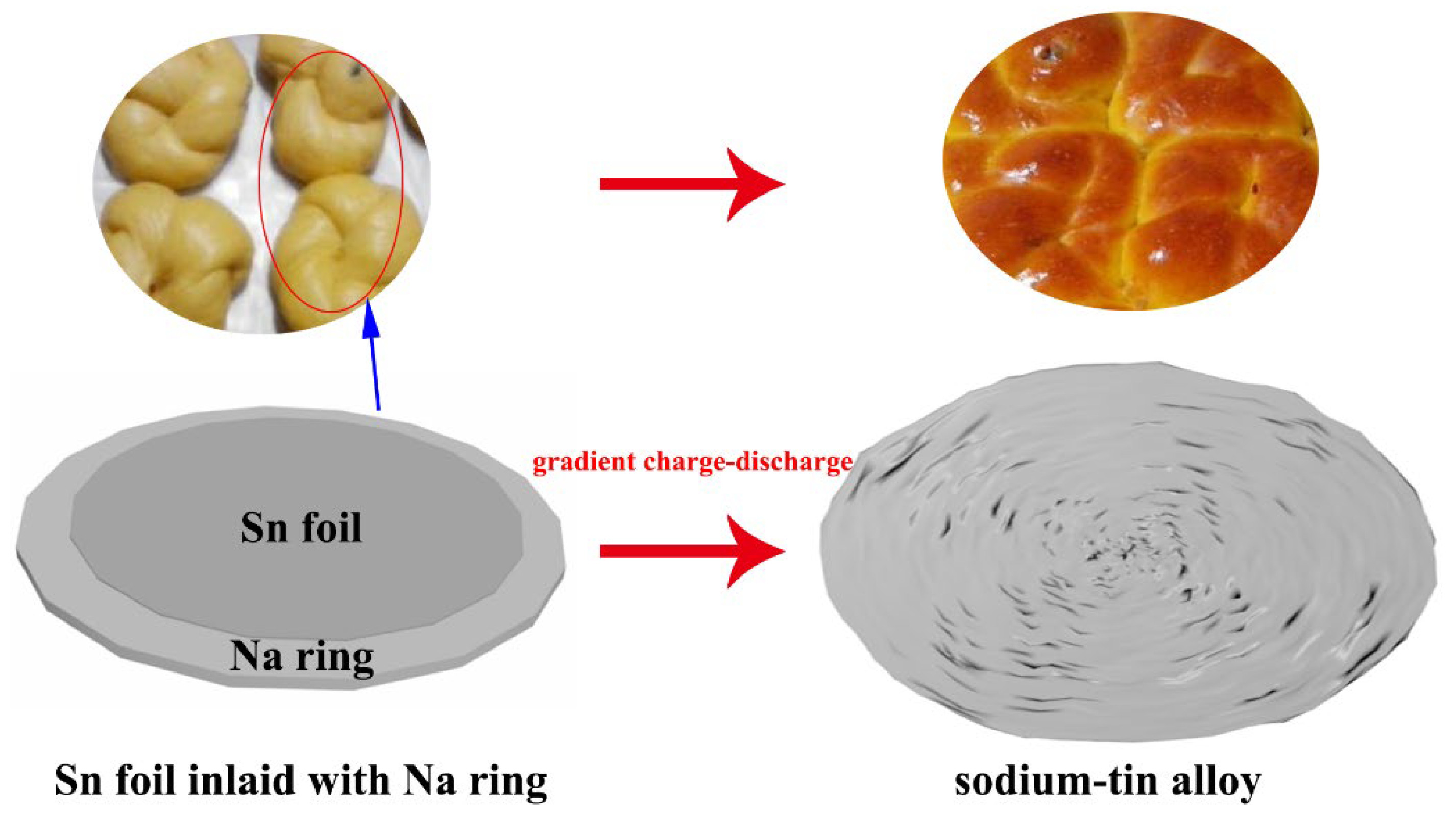
Figure 1. The schematic illustration for in situ electrochemical derivation of sodium-tin alloy.
Crystals 12 00575 g001
Figure 2. (a) The morphology of SCDC tested by FESEM, Raman (in the upper right of Figure 2a) and TEM (in the right bottom of Figure 2a); (b) Cyclic voltammetry curves of SCDC vs. Na/Na+ in different voltage ranges of 1.0–4.0 V, 1.5–4.0 V and 2.0–4.0 V; (c) Cyclic voltammetry curves of SCDC vs. Na/Na+ at different scan rate of 5 mV s−1, 10 mV s−1 and 20 mV s−1; (d) Comparison of gradient properties for pure Sn foil, pure Na metal disc and sodium-tin alloy anode in situ electrochemical derived from Sn foil inlaid with sodium ring.
Crystals 12 00575 g002
Figure 3. The electrochemical characteristic for sodium ion capacitors with SCDC as cathode and sodium-tin as anode; (a) curves of voltage vs. specific capacity for the first charge-discharge; (b) the gradient performance obtained from 0.1 to 6.4 A g−1 increasing by 2 times and circulates 10 laps for each current density; (c) the cyclic performance at 1 A g−1; (d) curves of voltage vs. specific capacity for the first 100 cycles of (c).
Crystals 12 00575 g003
Figure 4. (a) Cycle performance of Na0.91MnO2 hexagonal tablets (NMO HTs) vs. sodium-tin alloy in situ electrochemically derived directly collected for 570 cycles at 0.1 A g−1; (b) Capacity evolution of NMO HTs vs. sodium-tin alloy in situ electrochemically derived by evolving current densities ranging from 0.1, 0.2, 0.4, 0.8, 1.6 A g−1 and transfer to 0.1 A g−1 (inset, XRD of NMO HTs); (c) Cycle performance for 8400 cycles at 1 A g−1 directly collected after the various current densities for NMO HTs vs. sodium-tin alloy in situ electrochemically derived were tested; (d) The profiles of voltage vs. specific capacity for NMO HTs vs. sodium-tin alloy at 1.5–4.0 V between 4290th and 4300th cycles.
Crystals 12 00575 g004
Figure 5. (a) The first cyclic voltammetry of NMO HTs vs. Na/Na+ at 0.1 mV s−1; (b) Cyclic voltammetry curves of NMO HTs vs. Na/Na+ at different scan rate between 1.1 mV s−1 and 2.1 mV s−1 at intervals of 0.2 mV s−1; (c) The b-value determination of the peak currents of cathode shows that charge storage of SCDC vs. sodium-tin alloy; (d) Cyclic voltammetry curves of NMO HTs vs. Na/Na+ at 1.3 mV s−1 and the shadowed areas represent the capacitive contribution; (e) Separation of diffusion-controlled and capacitive charge at different sweep rates; (f) Nyquist dots of the NMO HTs vs. sodium-tin alloy in situ electrochemically derived by Sn foil (13 mm) inlaid with Na ring (1 mm) before and after 8400 cycles at 1 A g−1 (inset, the corresponding equivalent circuit diagram after 8400 cycles).
Crystals 12 00575 g005
Figure 6. Low magnification FESEM images of sodium-tin alloy derived by (a) pure Sn foil and (b) Sn foil inlaid with Na metal ring; (c)The representative district scanning and corresponding element mappings: (d) Na and (e) Sn; (f) the electron diffraction spectra (EDS) of sodium-tin alloy.
Crystals 12 00575 g006
Publisher’s Note: MDPI stays neutral with regard to jurisdictional claims in published maps and institutional affiliations.