Article

Analysis of Electromagnetic Effects on Vibration of Functionally Graded GPLs Reinforced Piezoelectromagnetic Plates on an Elastic Substrate

by
Mohammed Sobhy
1,2,* and
F. H. H. Al Mukahal
1
1
Department of Mathematics and Statistics, College of Science, King Faisal University, P.O. Box 400, Al-Ahsa 31982, Saudi Arabia
2
Department of Mathematics, Faculty of Science, Kafrelsheikh University, Kafrelsheikh 33516, Egypt
*
Author to whom correspondence should be addressed.
Crystals 2022, 12(4), 487; https://doi.org/10.3390/cryst12040487
Submission received: 22 February 2022 / Revised: 21 March 2022 / Accepted: 29 March 2022 / Published: 31 March 2022
(This article belongs to the Special Issue Photovoltaic Functional Crystals and Ceramics)

Abstract

:
A new nanocomposite piezoelectromagnetic plate model is developed for studying free vibration based on a refined shear deformation theory (RDPT). The present model is composed of piezoelectromagnetic material reinforced with functionally graded graphene platelets (FG-GPLs). The nanocomposite panel rests on Winkler–Pasternak foundation and is subjected to external electric and magnetic potentials. It is assumed that the electric and magnetic properties of the GPLs are proportional to those of the electromagnetic materials. The effective material properties of the plate are estimated based on the modified Halpin–Tsai model. A refined graded rule is introduced to govern the variation in the volume fraction of graphene through the thickness of the plate. The basic partial differential equations are provided based on Hamilton’s principle and then solved analytically to obtain the eigenfrequency for different boundary conditions. To check the accuracy of the present formulations, the depicted results are compared with the published ones. Moreover, impacts of the variation in elastic foundation stiffness, plate geometry, electric potential, magnetic potential, boundary conditions and GPLs weight fraction on the vibration of the smart plate are detailed and discussed.

1. Introduction

Due to the efficiency of piezoelectric and piezoelectromagnetic materials in converting electro-mechanical and magnetic energies to each other, such materials arise in a wide range of fields and industries including heat exchangers, smart devices, nuclear devices and electromechanical systems [1,2,3,4,5,6,7,8,9,10,11,12]. Moreover, such materials have a key role in nano-electro-mechanical systems such as sensors, actuators, nanogenerators, active controllers and nano-robotics [13]. Generally, nanocomposite structures reinforced with graphene are the main component of these devices since they are well-known for their stunning electro-mechanical properties. As a consequence of this, a large number of academic works have been devoted to investigate the properties of such materials. Based on the theory of linear piezoelectromagneticity, Hu and Li [8] obtained the expressions for singular stresses, electric displacements and magnetic fields in a piezoelectromagnetic plate with a Griffith crack subjected to longitudinal shear loads. Moreover, Ke and Wang [14] determined the linear natural frequencies of size-dependent electromagnetic nanobeams under external electric, magnetic potentials and a uniform temperature field based upon the nonlocal-Timoshenko beam theory and nonlocal elasticity theory. In another piece of research, Ke et al. [15] studied the free vibration behavior of magneto-electro-elastic (MEE) nanoplates employing the nonlocal and Kirchhoff plate theories. Employing the same mentioned nanobeams hypotheses, the bending, buckling and free vibration of MEE composites have been analyzed by Li et al. [16], taking into consideration the small-scale-dependent coefficients and the strength of the electric and induced magnetic fields on the transverse displacement, rotation, buckling loads and natural frequency. Exact solutions for anisotropic functionally graded and multi-layer MEE rectangular plates with material properties varying exponentially along the thickness direction were proposed by Pan and Han [17]. Farajpour et al. [18] depicted a nonlocal plate model to consider the size-effect on the nonlinear vibration behavior of MEE composite nanoplates subjected to external electromagnetic loading conditions. Furthermore, Farajpour et al. [19] considered the higher order deformations along with the higher and lower order nonlocal effects for the nonlinear bucking of orthotropic nanoplates in a thermal environment. Jamalpoor et al. [20] determined the closed-form solutions for natural frequencies and mechancial buckling loads of double-MEE nanoplate systems exposed to initial external electric voltage and magnetic potentials embedded in a viscoelastic medium. Mehditabar et al. [21] studied 3D magnetothermoelastic responses of FGM cylindrical shells using differential quadrature (DQ) technique subjected to non-uniform internal pressure. Under the influence of external electric voltage, Zenkour and Aljadani [22] determined the electro-mechanical buckling behavior of simply supported rectangular functionally-graded piezoelectric (FGP) plates using a quasi-3D refined plate theory. The impacts of various parameters, such as magnetic parameters, electrical potentials, rotation speed, thickness-to-radios ratio, and axial and circumferential wave numbers, on the free vibration of the rotating FG polymer cylindrical shells integrated by two piezo-electromagnetic (PEM) face sheets were evaluated by Meskini and Ghasemi [23]. Abazid and Sobhy [24] explained the thermal and EM size-dependent bending of simply-supported FG piezoelectric (FGP) microplates embedded on a Pasternak elastic foundation depending on a novel refined four-variable shear deformation plate theory, with the help of modified couple-stress theory. Nanoplate problems subjected to hygrothermal loads have been proposed in [25,26], using different nonlocal theories. Chen et al. [27] showed analytical formulations for the wave propagation studies in MEE multilayered plates with nonlocal properties, and selected two types of sandwich plates to investigate the nonlocal parameter on the dispersion curve. The impact of shear deformation and angular velocity on the wave propagation behaviours of MEE rotary nanobeams is performed by Ebrahimi and Dabbagh [28], using the nonlocal strain gradient theory (NSGT). Furthermore, the thermomechanical buckling, free vibration and wave propagation in smart piezoelectromagnetic nanoplates in a hygrothermal medium embedded in an elastic substrate was explored by Abazid [29]. In addition, some useful studies of sandwich structures in various configurations of FGPMs or FGPs, and subjected to various loadings, have also been performed by some eminent researchers [2,30,31,32].
Graphene reveals exceptionally superior electromechanical and physical properties (Potts et al. [33]), and is composed of a single thick layer of sp 2 joined carbon atoms arranged in a 2D hexagonal form. Graphene is the most powerful material that has been detected, since its tensile strength equals about 130.5 GPa, it has a Young’s modulus greater than 1 TPa, a mass of 1 m 2 is 0.77 mg and electrical conductivity 1000 times greater than copper for electric current-carrying capacity (Papageorgiou et al. [34]). Furthermore, the specific-surface-area of the graphene is exactly 2630 m 2 /g (Papageorgiou et al. [34]), whereas that of carbon nanotubes is in the range of 100–1000 m 2 /g. Graphene has been investigated as an ideal effective reinforcement of the piezoelectric material composite structures due to it enhances their electromechanical features and stiffness (see, e.g., Yang et al. [35], Forsat et al. [36], Khorasani et al. [11], Thai et al. [37,38] and Phung-Van et al. [39]). Mao et al. [40] presented the vibrational characteristics of the FG piezoelectric composite micro-plate reinforced with graphene nano-sheets (GNSs) upon the non-local constitutive relation and von-Karman geometric non-linearity, in which the equations of motion were solved via the differential quadrature (DQ) method. They showed that the concentration of graphene nano-platelets, exterior voltage, nonlocal parameters, geometrical and piezoelectric properties of the GNSs, as well as the elasticity parameters of the Winkler elastic foundation, has a key insight in the linear and nonlinear dynamic behaviors of the GNSs reinforcing FG piezoelectric composite micro-plates. Sobhy [41] developed an analytical method for the ME-thermal bending of FG-GNSs reinforced composite doubly-curved shallow shells surrounded by two smart face sheets of PEM with several boundary conditions. The obtained results of Mao and Zhang [42] showed that the piezoconductive characteristics of the GNSs nanofillers can significantly improve the stiffness of the FG-GNSs plates. Mao and Zhang [43] investigated the post-buckling and buckling properties of FG-GNSs plates subjected to electric potential and mechanical loads, in which the equations of motion were obtained by the combination of differential quadrature method and direct iterative technique. Furthermore, Sobhy et al. [44] investigated the change in thermal buckling in PFG-GNSs beams exposed to external electric voltage in a humid environment. In addition, some experimental works have shown that graphene reinforcements can obviously enhance the mechanical properties of the piezoelectric. Abolhasani et al. [45] investigated the influence of graphene reinforced PVDF (polyvinylidene fluoride) composites on the morphology, crystallinity, polymorphism and electrical outputs, on which the enhanced PVDF/graphene can be a potential application for portable self-powering devices. Xu et al.’s experiments [46] showed the positive piezoconductive impact in suspended graphene layers, which strongly depends on the layer-number.
As viewed in the above survey, many papers have been performed to study the behavior of GPL reinforced piezoelectric plates. However, the GPL reinforced piezoelectromagnetic (PEM) plate has not been considered in the literature. Motivated by this deficiency and to fill this gap, the present article is conducted to provide a comprehensive and clear scientific vision for the free vibration of piezoelectromagnetic plates reinforced with functionally graded graphene nanosheets (FG-GNSs) under simply supported conditions. In addition, a refined four-variable shear deformation theory is introduced to define the displacement field. The present nanocomposite panel is assumed to be resting on a Winkler–Pasternak foundation and subjected to external electric and magnetic potentials. The electric and magnetic properties of the GNSs are assumed to be proportional to those of the electromagnetic plate. Moreover, in accordance with the modified Halpin–Tsai model, the effective material properties of the plate are evaluated. To govern the variation in the volume fraction of graphene through the thickness of the plate, a refined graded rule is used. Hamilton’s principle is employed effectively to deduce equations of the motion mathematically, and then solved analytically to obtain the eigenfrequency. In order to validate the present formulations, the depicted results are compared with the published ones. Furthermore, the detailed parametric investigation of the variation in various parameters on the vibration of the smart plate are discussed.

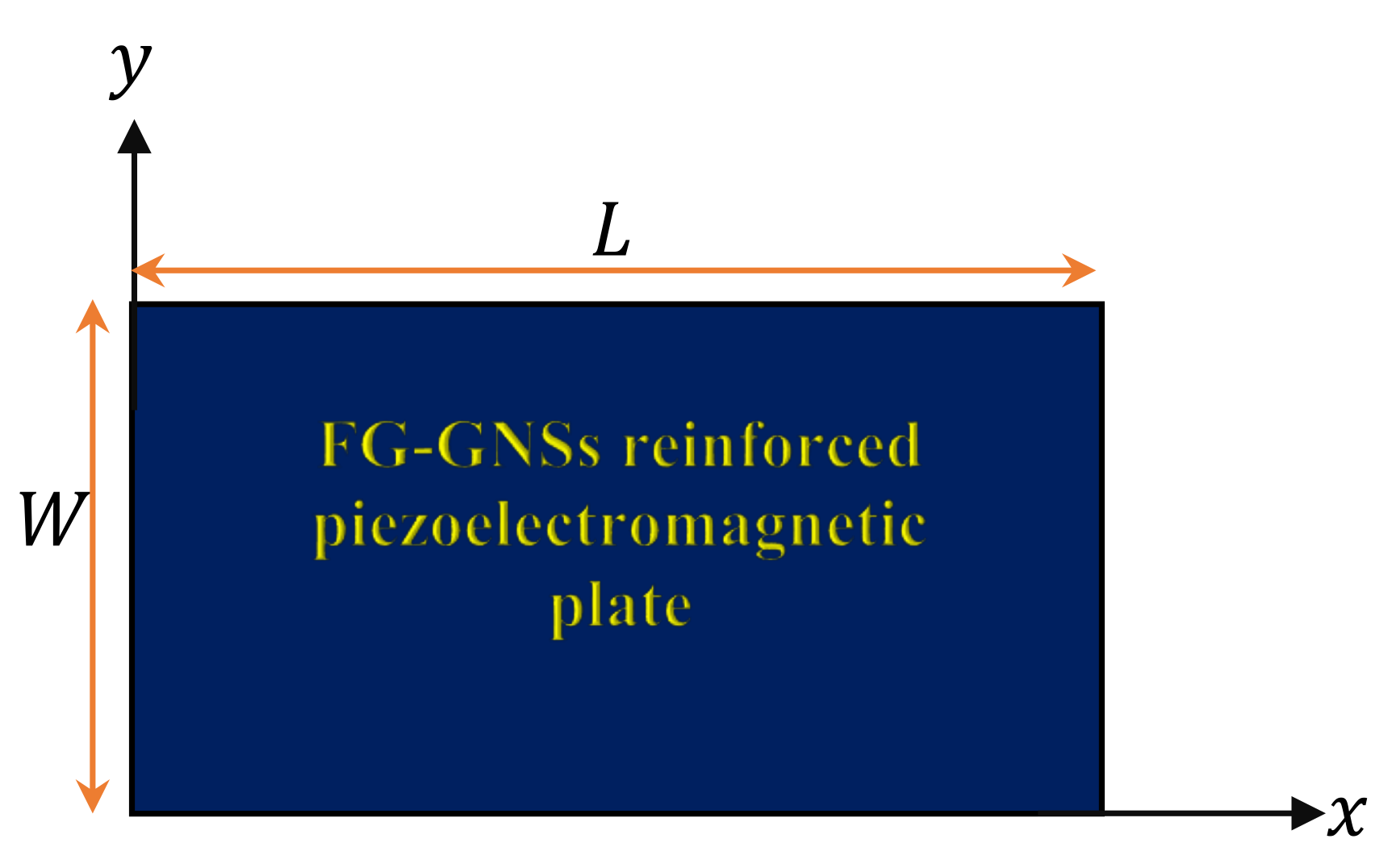
2. Plate Configuration

In this paper, we consider multi-layered piezoelectromagnetic plates reinforced with functionally graded graphene platelets with rectangular platform in which the length, width and total thickness are indicated by L, W and h, respectively, as displayed in Figure 1. The Cartesian coordinates system ( x , y , z ) is used to prescribe the infinitesimal deformations of the plate. This plate is assumed to be resting on a Winkler–Pasternak elastic substrate with stiffness ( J ^ 1 , J ^ 2 ) , and subjected to an external electric voltage and magnetic potential.
Within the framework of the modified Halpin–Tsai model, the effective Young’s modulus E ( i ) for the ith layer of the composite plate is given by [47,48,49]
E ( i ) = E p z m 8 3 1 + 2 κ 1 δ 1 G P V ( i ) G P 1 κ 1 V ( i ) G P + 5 1 + 2 κ 2 δ 2 G P V ( i ) G P 1 κ 2 V ( i ) G P ,
where E p z m is the piezoelectromagnetic Young’s modulus, δ 1 G P = L G P / h G P and δ 2 G P = W G P / h G P , in which L G P , W G P and h G P stand for the length, width and thickness of GNSs, respectively; V ( i ) G P denotes the volume fraction of graphene for the ith layer, and the coefficients κ 1 and κ 2 are displayed as
κ 1 = E G P E p z m E G P + 2 δ 1 G P E p z m , κ 2 = E G P E p z m E G P + 2 δ 2 G P E p z m ,
in which E G P indicates Young’s modulus of the GNSs. Moreover, the effective material properties of the FG-GNSs reinforced composite plate for the ith layer, namely Poisson’s ration ν i and mass density ρ i , can be evaluated as
ν i = V ( i ) G P ν G P + 1 V ( i ) G P ν p z m , ρ i = V ( i ) G P ρ G P + 1 V ( i ) G P ρ p z m ,
in which ν G P ( ν p z m ) and ρ G P ( ρ p z m ) are Poisson’s ratio of the GNSs (piezoelectromagnetic) and the mass density of the GNSs (piezoelectromagnetic), respectively. With respect to a modified piece-wise rule, the volume fraction of the GNSs will be varied across the thickness of the plate layers, as presented in Figure 2, and in the present analysis, four different cases of FG-GNSs distribution are considered as follows:

2.1. Type A

In the present case, the graphene platelets may be uniformly distributed throughout thickness h. As a result, the volume fraction of the ith layer can be written by
V ( i ) G P = V max G P = ρ p z m W G ρ p z m W G + ρ G P ( 1 W G ) , for UD
in which W G stands for the weight fraction of GNSs.

2.2. Type B

The volume fraction of graphene has a minimum value at the mid-plane of the sheets. While it equals a maximum value at the upper and lower sheets. Therefore, V ( i ) G P is written as
V ( i ) G P = V max G P | 2 i N 1 | 1 N 2 k for FG - X ,
in which N represents the number of layers of the plate, and 0 k is a power-law index.

2.3. Type C

In this particular case, the volume fraction of graphene decreases in a monotonic pattern from its maximum value V max G P at the top-surface, to a minimum value at the bottom-surface of the plate. We can denote the gradient-distributions of graphene by FG-V. Therefore, the volume fraction for each layer can be written as
V ( i ) G P = V max G P i 1 N 1 k for FG V .

2.4. Type D

In this state, the volume fraction of graphene equals zero at the top- and bottom-plate surfaces. It has a maximum value at the mid-plane of the plate. As a result, V ( i ) G P can be expressed as
V ( i ) G P = V max G P | 2 i N 1 | + 1 N 2 N k , for FG - O .

3. Constitutive Equations

A modified refined four-variable shear deformation plate theory ([50,51]), that is enhanced by introducing the bending and shear effects, is presented to describe the displacement components given by
U ( x , y , z ) V ( x , y , z ) W ( x , y , z ) = u 0 ( x , y ) v 0 ( x , y ) w b ( x , y ) + w s ( x , y ) z w b , x w b , y 0 f ( z ) w s , x w s , y 0
where u 0 ( x , y ) and v 0 ( x , y ) denote the component of the displacement of the mid-plane along the x- and y-axes, respectively. In accordance with the theory of Shimpi ([50]), the transverse deflection W ( x , y , z ) is divided into two components w b ( x , y ) and w s ( x , y ) which indicate the bending and shear displacements, respectively, and f ( z ) = z g ( z ) . In addition, in the above mentioned theory, a new-shape function is introduced which represents the configuration of the shear stress through the thickness of the plate, and it can be declared as
g ( z ) = z 1 + ( z / h ) 2 5 8 z 3 h 2 .
The definition of the shape function g ( z ) allows the recovery of a variety of theories in the literature, such as the third-order theory (TDPT) [52] g ( z ) = z 4 z 3 / 3 h 2 , the sinusoidal theory (SDPT) [53] g ( z ) = ( h / π ) sin ( z π / h ) , and the exponential theory (EDPT) [54] g ( z ) = z e 2 z 2 / h 2 . Based on the displacement field (8), one can obtain the components of the strains as:
ε x x ε y y ε x y = ε x x ( 0 ) ε y y ( 0 ) ε x y ( 0 ) + z ε x x ( 1 ) ε y y ( 1 ) ε x y ( 1 ) + f ( z ) ε x x ( 2 ) ε y y ( 2 ) ε x y ( 2 ) , ε x z ε y z = g ε x z ( 2 ) ε y z ( 2 ) , g = d g d z ,
where
ε x x ( 0 ) ε y y ( 0 ) ε x y ( 0 ) = u 0 , x v 0 , y u 0 , y + v 0 , x , ε x x ( 1 ) ε y y ( 1 ) ε x y ( 1 ) = w b , x x w b , y y 2 w b , x y , ε x x ( 2 ) ε y y ( 2 ) ε x y ( 2 ) = w s , x x w s , y y 2 w s , x y , ε x z ( 2 ) ε y z ( 2 ) = w s , x w s , y .
In respect to the piezoelasticity theory [2,14,41,55], the constitutive relation for the components of the stresses σ can be expressed as follows
σ x x σ y y σ y z σ x z σ x y ( i ) = C 11 C 12 0 0 0 C 12 C 22 0 0 0 0 0 C 44 0 0 0 0 0 C 55 0 0 0 0 0 C 66 ( i ) ε x x ε y y ε y z ε x z ε x y 0 0 ξ 13 0 0 ξ 23 0 ξ 24 0 ξ 15 0 0 0 0 0 ( i ) E ^ 1 E ^ 2 E ^ 3 0 0 η 13 0 0 η 23 0 η 24 0 η 15 0 0 0 0 0 ( i ) M 1 M 2 M 3
where ( C 11 , C 12 , C 22 , C 44 , C 55 , C 66 ) denote the elastic coefficients of the FG-GNSs composite plate which are expressed as:
C 11 ( i ) = C 22 ( i ) = E ( i ) 1 ν ( i ) 2 , C 12 ( i ) = ν ( i ) E ( i ) 1 ν ( i ) 2 , C 44 ( i ) = C 55 ( i ) = C 66 ( i ) = E ( i ) 2 1 + ν ( i ) .
Furthermore, the remaining coefficients of piezoelectromagnetic and dielectric ( ξ 13 , ξ 23 , ξ 24 , ξ 15 ) and ( η 13 , η 23 , η 24 , η 15 ) , respectively, can be calculated as follows:
ξ j k ( i ) = V ( i ) G P ξ j k G P + 1 V ( i ) G P ξ j k , p z m η j k ( i ) = V ( i ) G P η j k G P + 1 V ( i ) G P η j k , p z m , j , k = 1 , 2 , , 5 ,
where ξ j k G P ( ξ j k , p z m ) and η j k G P ( η j k , p z m ) denote the piezoelectric coefficients of GNSs (piezoelectromagnetic), and the dielectric coefficients of GNSs (piezoelectromagnetic), respectively. The electric displacements D i and the magnetic induction B i are written as
D x D y D z ( i ) = 0 0 0 ξ 15 0 0 0 ξ 24 0 0 ξ 13 ξ 23 0 0 0 ( i ) ε x x ε y y ε y z ε x z ε x y + f 11 0 0 0 f 22 0 0 0 f 33 ( i ) E ^ 1 E ^ 2 E ^ 3 + g 11 0 0 0 g 22 0 0 0 g 33 ( i ) M 1 M 2 M 3 ,
B x B y B z ( i ) = 0 0 0 η 15 0 0 0 η 24 0 0 η 13 η 23 0 0 0 ( i ) ε x x ε y y ε y z ε x z ε x y + g 11 0 0 0 g 22 0 0 0 g 33 ( i ) E ^ 1 E ^ 2 E ^ 3 + r 11 0 0 0 r 22 0 0 0 r 33 ( i ) M 1 M 2 M 3 ,
where ( f 11 , f 22 , f 33 ) , ( g 11 , g 22 , g 33 ) , and ( r 11 , r 22 , r 33 ) denote, respectively, the dielectric, magneto-electric and magnetic constants of the FG-GNSs composite plate, which can be defined as follows
f j j ( i ) = V ( i ) G P f j j G P + 1 V ( i ) G P f j j , p z m g j j ( i ) = V ( i ) G P g j j G P + 1 V ( i ) G P g j j , p z m , j = 1 , 2 , 3 r j j ( i ) = V ( i ) G P r j j G P + 1 V ( i ) G P r j j , p z m ,
The electric field E ^ and magnetic field M can take the following form [14,41]:
E ^ = Φ , M = Ψ
where Φ and Ψ represent, respectively, the electric and magnetic potentials of the FG-GNSs composite plate that can defined as [14,41]:
Φ ( x , y , z ) = ϕ ( x , y ) cos π z h + 2 z V ^ 0 h , Ψ ( x , y , z ) = ψ ( x , y ) cos π z h + 2 z P ^ 0 h ,
in which V ^ 0 and P ^ 0 are, respectively, the external applied electric and magnetic potentials, ϕ ( x , y ) and ψ ( x , y ) denote the electric and magnetic potentials of the middle surface of the plate. Substituting Equation (19) into Equation (18) gives the components of the electric and magnetic fields
E ^ 1 E ^ 2 E ^ 3 = ϕ , x cos π z h ϕ , y cos π z h π h ϕ sin π z h 0 0 2 V ^ 0 h M 1 M 2 M 3 = ψ , x cos π z h ψ , y cos π z h π h ψ sin π z h 0 0 2 P ^ 0 h .

4. Governing Equations

In order to establish the equations of motion associated with the displacement field in Equation (8), the variation in the strain energy δ K S , the kinetic energy δ K K , the work done by the in-plane piezoelectromagnetic load K EM and the elastic foundations δ K F can be stated by Hamilton’s principle
0 t δ K S + δ K K δ K EM δ K F d t = 0 ,
where
δ K S = i = 1 N V σ j k ( i ) δ ε j k D j ( i ) δ E ^ j B j ( i ) δ M j d V , δ K K = i = 1 N V ρ ( i ) u ¨ δ u + v ¨ δ v + w ¨ δ w d V , δ K EM = A N E + N M 2 w x 2 + 2 w y 2 δ w d A , δ K F = A J ^ 1 w J ^ 2 2 w δ w d A ,
in which J ^ 1 and J ^ 2 denote, respectively, the springs and shear layer foundation stiffness, N E and N M denote the in-plane hygrothermal forces which are defined, respectively, as
N E = i = 1 N h i h i + 1 ξ 13 ( i ) 2 V ^ 0 h d z , N M = i = 1 N h i h i + 1 η 13 ( i ) 2 P ^ 0 h d z .
Substituting ε j k , E ^ j and M j into the first equation of Equation (22) gives
δ K s = i = 1 N V [ σ x x ( i ) δ ε x x ( 0 ) + z ε x x ( 1 ) + f ε x x ( 2 ) + σ y y ( i ) δ ε y y ( 0 ) + z ε y y ( 1 ) + f ε y y ( 2 ) + σ x y ( i ) δ ε x y ( 0 ) + z ε x y ( 1 ) + f ε x y ( 2 ) + σ x z ( i ) δ g ε x z ( 2 ) + σ y z ( i ) δ g ε y z ( 2 ) D 1 ( i ) δ ϕ x cos π z h D 2 ( i ) δ ϕ y cos π z h + D 3 ( i ) δ π ϕ h sin π z h B 1 ( i ) δ ψ x cos π z h B 2 ( i ) δ ψ y cos π z h + B 3 ( i ) δ π ψ h sin π z h ] d V ,
or
δ K s = A [ N ^ x x δ ε x x ( 0 ) + M ^ x x δ ε x x ( 1 ) + S x x δ ε x x ( 2 ) + N ^ y y δ ε y y ( 0 ) + M ^ y y δ ε y y ( 1 ) + S y y δ ε y y ( 2 ) + N ^ x y δ ε x y ( 0 ) + M ^ x y δ ε x y ( 1 ) + S x y δ ε x y ( 2 ) + Q x z δ ε x z ( 2 ) + Q y z δ ε y z ( 2 ) R 1 δ ϕ x R 2 δ ϕ y + R 3 δ ϕ T 1 δ ψ x T 2 δ ψ y + T 3 δ ψ ] d A ,
where
{ N ^ x x , M ^ x x , S x x } = i = 1 N h i h i + 1 σ x x ( i ) { 1 , z , f } d z , { N ^ y y , M ^ y y , S y y } = i = 1 N h i h i + 1 σ y y ( i ) { 1 , z , f } d z , { N ^ x y , M ^ x y , S x y } = i = 1 N h i h i + 1 σ x y ( i ) { 1 , z , f } d z , { Q x z , Q y z } = i = 1 N h i h i + 1 g { σ x z ( i ) , σ y z ( i ) } d z ,
R 1 = i = 1 N h i h i + 1 D 1 ( i ) cos π z h d z , R 2 = i = 1 N h i h i + 1 D 2 ( i ) cos π z h d z , R 3 = i = 1 N h i h i + 1 D 3 ( i ) π h sin π z h d z , T 1 = i = 1 N h i h i + 1 B 1 ( i ) cos π z h d z , T 2 = i = 1 N h i h i + 1 B 2 ( i ) cos π z h d z , T 3 = i = 1 N h i h i + 1 B 3 ( i ) π h sin π z h d z ,
By substituting σ i j ( i ) , D i and B i into Equations (26) and (27), we can obtain
N ^ 11 N ^ 22 M ^ 11 M ^ 22 S 11 S 22 R 3 T 3 = a 11 a 12 a 13 b 11 b 12 b 13 b 11 b 12 b 13 b 21 b 22 b 23 a 12 a 32 a 33 b 12 b 32 b 33 b 12 b 32 b 33 b 22 b 42 b 43 a 13 a 33 a 53 b 13 b 33 b 53 b 13 b 33 b 53 b 23 b 43 b 63 d 11 d 31 d 51 d 21 d 41 d 61 d 12 d 32 d 52 d 22 d 42 d 62 ε 11 ( 0 ) ε 11 ( 1 ) ε 11 ( 2 ) ε 22 ( 0 ) ε 22 ( 1 ) ε 22 ( 2 ) + d 11 d 21 d 31 d 41 d 51 d 61 d ¯ 11 d ¯ 12 ϕ + d 12 d 22 d 32 d 42 d 52 d 62 d ¯ 12 d ¯ 22 ψ + N 1 E + N 1 M N 2 E + N 2 M M ^ 1 E + M ^ 1 M M ^ 2 E + M ^ 2 M S 1 E + S 1 M S 2 E + S 2 M R 3 E + R 3 M T 3 E + T 3 M
N ^ 12 M ^ 12 S 12 = a ¯ 31 a ¯ 32 a ¯ 33 a ¯ 32 a ¯ 42 a ¯ 43 a ¯ 33 a ¯ 43 a ¯ 53 ε 12 ( 0 ) ε 12 ( 1 ) ε 12 ( 2 )
Q 13 R 1 T 1 = a ^ 11 a ^ 12 E a ^ 13 M a ^ 12 E a ^ 13 E a ^ 14 E a ^ 13 M a ^ 14 E a ^ 33 M ε 13 ( 2 ) ϕ , x ψ , x Q 23 R 2 T 2 = a ^ 21 a ^ 22 E a ^ 23 M a ^ 22 E a ^ 23 E a ^ 24 E a ^ 23 M a ^ 24 E a ^ 43 M ε 23 ( 2 ) ϕ , y ψ , y
where
{ a 11 , a 12 , a 13 , a 32 , a 33 , a 53 } = i = 1 N h i h i + 1 C 11 ( i ) { 1 , z , f , z 2 , z f , f 2 } d z , { b 11 , b 12 , b 13 , b 32 , b 33 , b 53 } = i = 1 N h i h i + 1 C 12 ( i ) { 1 , z , f , z 2 , z f , f 2 } d z , { b 21 , b 22 , b 23 , b 42 , b 43 , b 63 } = i = 1 N h i h i + 1 C 22 ( i ) { 1 , z , f , z 2 , z f , f 2 } d z , d 11 , d 12 d 31 , d 32 d 51 , d 52 = i = 1 N h i h i + 1 π h sin π z h 1 z f { ξ 13 ( i ) , η 13 ( i ) } d z , d 21 , d 22 d 41 , d 42 d 61 , d 62 = i = 1 N h i h i + 1 π h sin π z h 1 z f { ξ 23 ( i ) , η 23 ( i ) } d z , { d ¯ 11 , d ¯ 12 , d ¯ 13 } = i = 1 N h i h i + 1 π h 2 sin 2 π z h { f 33 ( i ) , g 33 ( i ) , r 33 ( i ) } d z ,
N 2 E M ^ 2 E S 2 E = i = 1 N h i h i + 1 2 V ^ 0 h 1 z f ξ 23 ( i ) d z , N 2 M , M ^ 2 M S 2 M = i = 1 N h i h i + 1 2 P ^ 0 h 1 z f η 23 ( i ) d z , M ^ 1 E S 1 E = i = 1 N h i h i + 1 2 V ^ 0 h z f ξ 13 ( i ) d z , M ^ 1 M S 1 M = i = 1 N h i h i + 1 2 P ^ 0 h z f η 13 ( i ) d z , { R 3 E , T 3 E } = i = 1 N h i h i + 1 { f 33 ( i ) , g 33 ( i ) } 2 V ^ 0 h π h sin π z h d z , { R 3 M , T 3 M } = i = 1 N h i h i + 1 { g 33 ( i ) , r 33 ( i ) } 2 P ^ 0 h π h sin π z h d z ,
{ a ¯ 31 , a ¯ 32 , a ¯ 33 , a ¯ 42 , a ¯ 43 , a ¯ 53 } = i = 1 N h i h i + 1 C 66 ( i ) { 1 , z , f , z 2 , z f , f 2 } d z , { a ^ 11 , a ^ 21 } = i = 1 N h i h i + 1 { C 55 ( i ) , C 44 ( i ) } g 2 d z , { a ^ 12 E , a ^ 22 E , a ^ 13 M , a ^ 23 M } = i = 1 N h i h i + 1 g cos π z h { ξ 15 ( i ) , ξ 24 ( i ) , η 15 ( i ) , η 24 ( i ) } d z , { a ^ 13 E , a ^ 14 E , a ^ 33 M , a ^ 23 E , a ^ 24 E , a ^ 43 M } = i = 1 N h i h i + 1 { f 11 ( i ) , g 11 ( i ) , r 11 ( i ) , f 22 ( i ) , g 22 ( i ) , r 22 ( i ) } cos 2 π z h d z ,
Substituting Equations (22) and (25) into Equation (21) leads to the equation of motion as follows:
N ^ x x x + N ^ x y y = I 11 u ¨ 0 I 12 w ¨ b x I 13 w ¨ s x , N ^ x y x + N ^ y y y = I 11 v ¨ 0 I 12 w ¨ b y I 13 w ¨ s y , 2 M ^ x x x 2 + 2 2 M ^ x y x y + 2 M ^ y y y 2 J 1 w + J 2 2 w + ( N E + N M ) 2 w = I 11 w ¨ + I 12 u ¨ 0 x + v ¨ 0 y 2 I 22 w ¨ b + I 23 w ¨ s , 2 S x x x 2 + 2 2 S x y x y + 2 S y y y 2 J 1 w + J 2 2 w + ( N E + N M ) 2 w = I 11 w ¨ + I 13 u ¨ 0 x + v ¨ 0 y 2 I 23 w ¨ b + I 33 w ¨ s , R 1 x + R 2 y + R 3 = 0 , T 1 x + T 2 y + T 3 = 0 ,
where
{ I 11 , I 12 , I 13 , I 22 , I 23 , I 33 } = i = 1 N h i h i + 1 ρ ( i ) { 1 , z , f , z 2 , z f , f 2 } d z .

5. Solution Procedure

The natural frequency of the FG-GNSs reinforced piezoelectromagnetic rectangular plate is deduced by solving the governing motion Equations (34) with different boundary conditions.
Simply supported (S)
v 0 = w b = w s = ϕ = ψ = w b y = w s y = N ^ x x = M ^ x x = S x x = 0 , at x = 0 , L , u 0 = w b = w s = ϕ = ψ = w b x = w s x = N ^ y y = M ^ y y = S y y = 0 at y = 0 , W .
Clamped (C)
u 0 = v 0 = w i = ϕ = ψ = w i x = w i y = 0 , at x = 0 , L , y = 0 , W , i = b , s .
According to the above boundary conditions, the displacements can be assumed as:
u 0 = m l U m l X m ( x ) x X ¯ l ( y ) , v 0 = m l V m l X m ( x ) X ¯ l ( y ) y , { w b , w s , ϕ , ψ } = m l { W ¯ b m l , W ¯ s m l , ϕ ¯ m l , ψ ¯ m l } X m ( x ) X ¯ l ( y ) ,
where U m l , V m l , W b m l , W s m l , ϕ ¯ m l and ψ ¯ m l are unknown functions. The admissible functions X m ( x ) and X ¯ l ( y ) are given in Table 1, noting that λ = m π / L and μ = l π / W .
Incorporating Equation (38) into Equations (28)–(30) and then Equation (34) leads to the equations of motion of the nanocomposite piezoelectromagnetic plate as follows:
Y 11 Y 12 Y 13 Y 14 Y 15 Y 16 Y 21 Y 22 Y 23 Y 24 Y 25 Y 26 Y 31 Y 32 Y 33 Y 34 Y 35 Y 36 Y 41 Y 42 Y 43 Y 44 Y 45 Y 46 Y 51 Y 52 Y 53 Y 54 Y 55 Y 56 Y 61 Y 62 Y 63 Y 64 Y 65 Y 66 U m l V m l W b m l W s m l ϕ ¯ m l ϕ ¯ m l = 0 ,
where the elements of the matrix [ Y ] are given as:
Y 11 = a 11 q 2 + a ¯ 31 q 3 + I 11 q 1 ω 2 , Y 12 = b ¯ 31 q 3 + b 11 q 3 , Y 13 = a 12 q 2 I 12 q 1 ω 2 2 b ¯ 32 q 3 b 12 q 3 , Y 14 = a 13 q 2 I 13 q 1 ω 2 2 b ¯ 33 q 3 b 13 q 3 , Y 15 = d 11 q 1 , Y 16 = d 12 q 1 , Y 21 = a ¯ 31 q 6 + b 11 q 6 , Y 22 = b ¯ 31 q 6 + a 11 q 5 + I 11 q 4 ω 2 , Y 23 = a 12 q 5 I 12 q 4 ω 2 2 b ¯ 32 q 6 b 12 q 6 , Y 24 = a 13 q 5 I 13 q 4 ω 2 2 b ¯ 33 q 6 b 13 q 6 , Y 25 = d 11 q 4 , Y 26 = d 12 q 4 , Y 31 = a 12 q 11 + I 12 q 9 ω 2 + 2 b ¯ 32 q 10 + b 12 q 10 , Y 32 = a 12 q 12 + I 12 q 8 ω 2 + 2 b ¯ 32 q 10 + b 12 q 10 , Y 33 = I 11 q 7 ω 2 J ^ 1 q 7 + N 1 E q 8 + N 1 M q 8 + N 1 E q 9 + N 1 M q 9 a 22 q 11 a 22 q 12 + J ^ 2 q 8 + J ^ 2 q 9 I 22 q 8 ω 2 I 22 q 9 ω 2 4 b ¯ 42 q 10 2 b 22 q 10 , Y 34 = I 11 q 7 ω 2 J ^ 1 q 7 + N 1 E q 8 + N 1 M q 8 + N 1 E q 9 + N 1 M q 9 a 23 q 11 a 23 q 12 + J ^ 2 q 8 + J ^ 2 q 9 I 23 q 8 ω 2 I 23 q 9 ω 2 4 b ¯ 43 q 10 2 b 23 q 10 , Y 35 = d 31 q 8 + d 31 q 9 , Y 36 = d 32 q 8 + d 32 q 9 , Y 41 = a 13 q 11 + I 13 q 9 ω 2 + 2 b ¯ 33 q 10 + b 13 q 10 , Y 42 = a 13 q 12 + I 13 q 8 ω 2 + 2 b ¯ 33 q 10 + b 13 q 10 , Y 43 = I 11 q 7 ω 2 J ^ 1 q 7 + N 1 E q 8 + N 1 M q 8 + N 1 E q 9 + N 1 M q 9 a 23 q 11 a 23 q 12 + J ^ 2 q 8 + J ^ 2 q 9 I 23 q 8 ω 2 I 23 q 9 ω 2 4 b ¯ 43 q 10 2 b 23 q 10 , Y 44 = I 11 q 7 ω 2 J ^ 1 q 7 + N 1 E q 8 + N 1 M q 8 + N 1 E q 9 + N 1 M q 9 a 33 q 11 + a ^ 11 q 8 a 33 q 12 + a ^ 11 q 9 + J ^ 2 q 8 + J ^ 2 q 9 I 33 q 8 ω 2 I 33 q 9 ω 2 4 b ¯ 53 q 10 2 b 33 q 10 , Y 45 = a ^ 12 E q 8 a ^ 12 E q 9 + d 51 q 8 + d 51 q 9 , Y 46 = a ^ 13 M q 8 a ^ 13 M q 9 + d 52 q 8 + d 52 q 9 , Y 51 = d 11 q 9 , Y 52 = d 11 q 8 , Y 53 = d 31 q 8 d 31 q 9 , Y 54 = a ^ 12 E q 8 + a ^ 12 E q 9 d 51 q 8 d 51 q 9 , Y 55 = a ^ 23 E q 8 + a ^ 23 E q 9 d ¯ 11 q 7 , Y 56 = a ^ 14 E q 8 + a ^ 14 E q 9 d ¯ 12 q 7 , Y 61 = d 12 q 9 , Y 62 = d 12 q 8 , Y 63 = d 32 q 8 d 32 q 9 , Y 64 = a ^ 13 M q 8 + a ^ 13 M q 9 d 52 q 8 d 52 q 9 , Y 65 = a ^ 14 E q 8 + a ^ 14 E q 9 d ¯ 12 q 7 , Y 66 = a ^ 33 M q 8 + a ^ 33 M q 9 d ¯ 22 q 7 .
where
q 1 = 0 L 0 W X m ( x ) x X ¯ l ( y ) 2 d y d x , q 2 = 0 L 0 W X m ( x ) x 3 X m ( x ) x 3 X ¯ l ( y ) 2 d y d x , q 3 = 0 L 0 W X m ( x ) x 2 X ¯ l ( y ) 2 X ¯ l ( y ) y 2 d y d x , q 4 = 0 L 0 W X m ( x ) X ¯ l ( y ) y 2 d y d x , q 5 = 0 L 0 W X m ( x ) 2 X ¯ l ( y ) y 3 p X ¯ l ( y ) y 3 d y d x , q 6 = 0 L 0 W X m ( x ) 2 p X m ( x ) x 2 X ¯ l ( y ) y 2 d y d x , q 7 = 0 L 0 W X m ( x ) X ¯ l ( y ) 2 d y d x , q 8 = 0 L 0 W X m ( x ) 2 X ¯ l ( y ) 2 X ¯ l ( y ) y 2 d y d x , q 9 = 0 L 0 W X m ( x ) X ¯ l ( y ) 2 2 p X m ( x ) x 2 d y d x , q 10 = 0 L 0 W X m ( x ) X ¯ l ( y ) 2 p X m ( x ) x 2 2 X ¯ l ( y ) y 2 d y d x , q 11 = 0 L 0 W X m ( x ) X ¯ l ( y ) 2 4 p X m ( x ) x 4 d y d x , q 12 = 0 L 0 W X m ( x ) 2 X ¯ l ( y ) 4 X ¯ l ( y ) y 4 d y d x .
For a nontrivial solution, the determinante | Y | should be equal to zero. Solving the equation | Y | = 0 gives the eigenfrequency of the nanocomposite piezoelectromagnetic plate resting on an elastic substrate.

6. Results and Discussion

In this section, the numerical results of the above formulations are developed for the free vibration of a piezoelectromagnetic plate strengthened by GNSs for different boundary conditions. The material properties of the piezoelectromagnetic material are taken as [14]: E p z m = 141 GPa, μ p z m = 0.35 , ρ p z m = 5.55 g / cm 3 , ξ 13 , p z m = ξ 23 , p z m = 2.2 Cm 2 , ξ 24 , p z m = ξ 15 , p z m = 5.8 Cm 2 , η 13 , p z m = η 23 , p z m = 290.1 NA 1 m 1 , η 24 , p z m = η 15 , p z m = 275 NA 1 m 1 , f 11 , p z m = f 22 , p z m = 5.64 × 10 9 CV 1 m 1 , f 33 , p z m = 6.35 × 10 9 CV 1 m 1 , g 11 , p z m = g 22 , p z m = 5.367 × 10 12 NsV 1 C 1 , g 33 , p z m = 2737.5 × 10 12 NsV 1 C 1 , r 11 , p z m = r 22 , p z m = 297 × 10 6 Ns 2 C 2 , r 33 , p z m = 83.5 × 10 6 Ns 2 C 2 . While the mechanical properties of graphene are given as [41]: E G P = 1010 GPa , ρ G P = 1.06 g / cm 3 , ν G P = 0.186 . In addition, the electromagnetic properties of the graphene nanosheets are assumed to be proportional to that of the piezoelectromagnetic material as: ξ i j G P = χ ξ i j , p z m , ξ i j G P = χ ξ i j , p z m , η i j G P = χ η i j , p z m , f i j G P = χ f i j , p z m , g i j G P = χ g i j , p z m , r i j G P = χ r i j , p z m , where χ is the piezoelectromagnetic multiple. The following fixed data have been used (except otherwise stated): m = l = 1 , N = 10 , L G P = 15 nm, W G P = 9 nm, h G P = 0.188 nm, W G = 0.1 , L / h = 10 , L / W = 1 , k = 1 , V 0 = 1 , P 0 = 0.1 , h = 2 mm, χ = 100 , J 1 = 100 , J 2 = 10 . For convenience, the ensuing nondimensional quantities are defined:
Ω = 100 h ω ρ p z m E p z m , J 1 = J ^ 1 L 4 D p z m , J 2 = J ^ 2 L 2 D p z m V 0 = V ^ 0 L D p z m , P 0 = P ^ 0 L D p z m , D p z m = E p z m h 3 12 [ 1 ( ν p z m ) 2 ] .

6.1. Verification

To confirm the accuracy of the current formulations and results, the present outcomes are compared with those depicted by Thai and Choi [56] and Baferani et al. [57]. Three comparison examples are performed, namely for the FG plate without an elastic foundation, resting on a Winkler elastic foundation and resting on a Pasternak elastic foundation as shown in Table 2, Table 3 and Table 4. In these tables, the nondimensional frequency Ω ^ of Al/Al 2 O 3 (aluminum/alumina) FG plate is presented for different values of the side-to-thickness ratio L / h and the power law index n, and for different shear deformation plate theories. The effective Young’s modulus and density are calculated via the following mixture law:
E = E m + ( E c E m ) z h + 1 2 n , ρ = ρ m + ( ρ c ρ m ) z h + 1 2 n ,
where E m = 70 GPa, ρ m = 2.707 g / cm 3 , E c = 380 GPa, ρ c = 3.8 g / cm 3 . While Poisson’s ratio is given as ν = 0.3 . It is noted from Table 2, Table 3 and Table 4 that the results of the present theory are in a good agreement with the published ones.
Another comparison example is developed here for the natural frequencies Ω ¯ of a homogeneous piezoelectromagnetic plate without elastic foundations for different values of the mode numbers as shown in Table 5. The mechanical and electromagnetic properties of the plate are taken as in Refs. [14,29]. Once again, an excellent agreement between the present frequencies and those depicted by Abazid [29] and Ke et al. [14] is also observed.

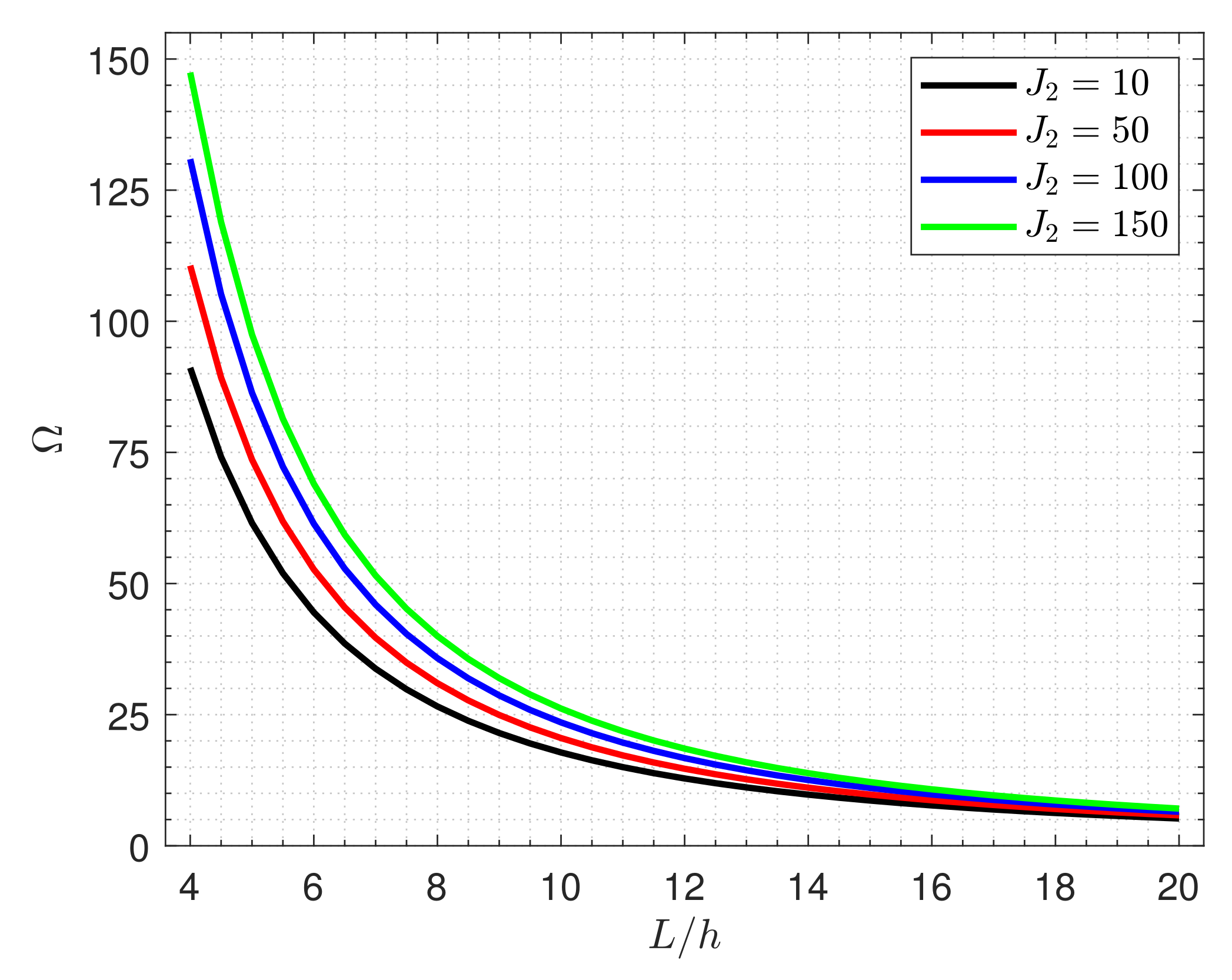
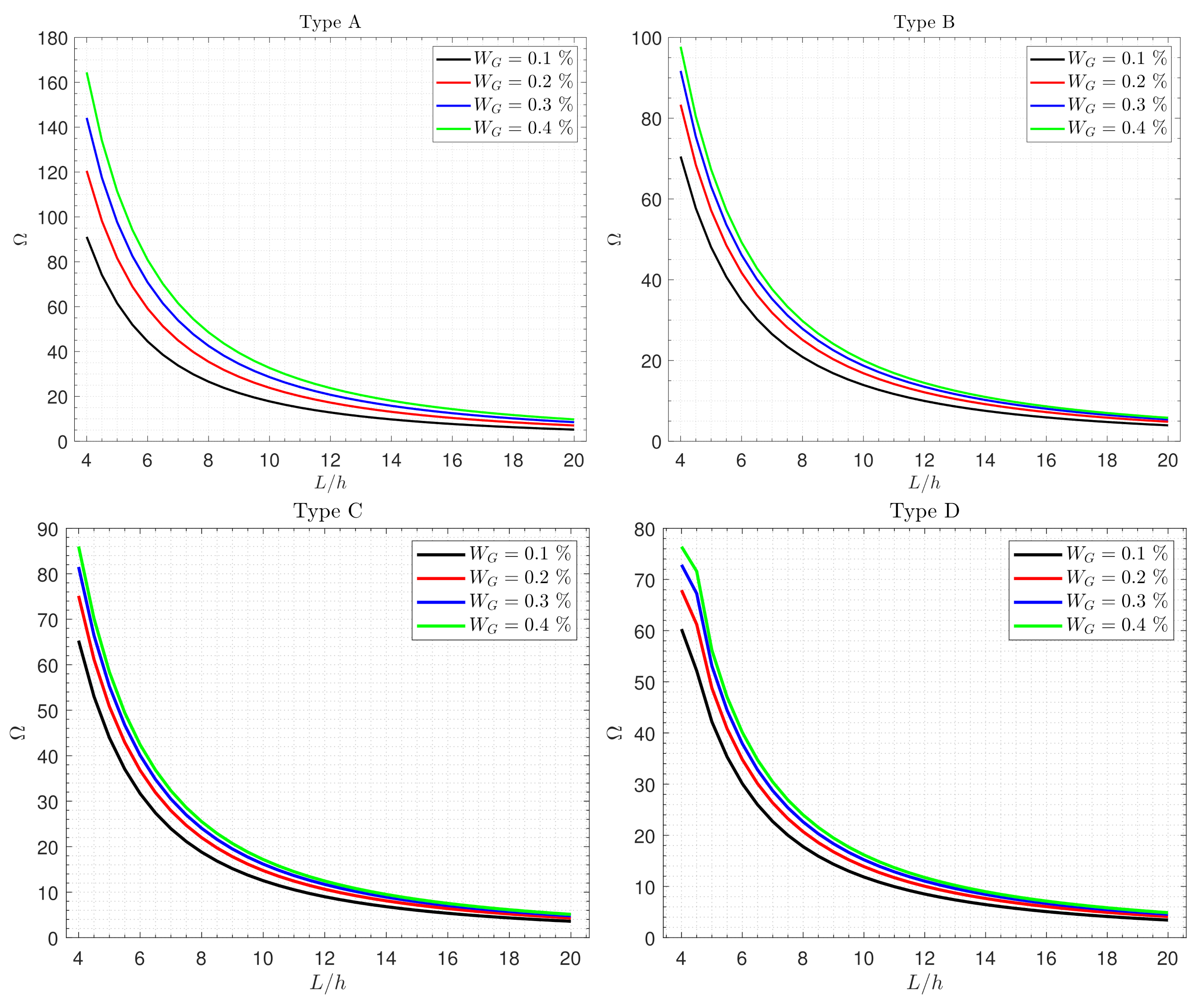
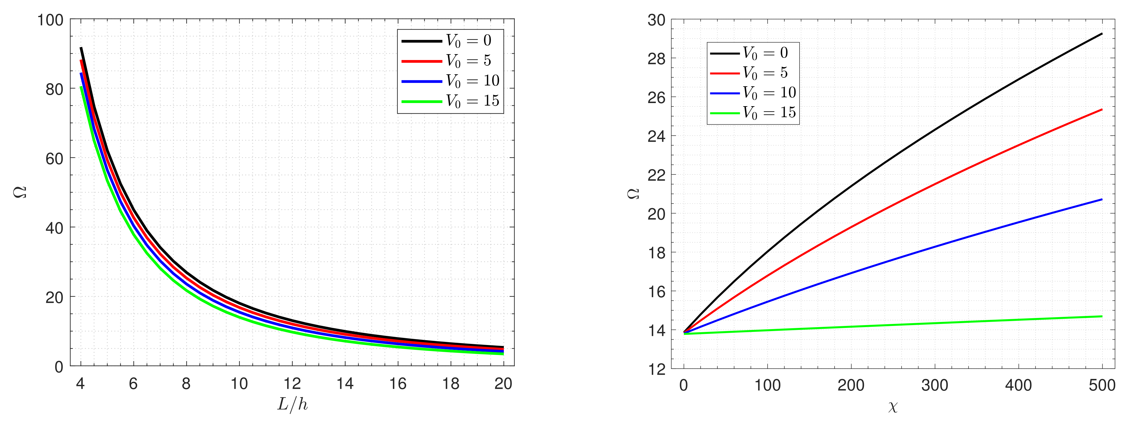
6.2. Parametric Results

In this subsection, we will discuss the effects of the elastic foundation parameter, graphene weight fraction, power-law index, side-to-thickness ratio, external applied electric and magnetic potentials and piezoelectromagnetic multiple on the fundamental frequency of the nanocomposite piezoelectromagnetic rectangular plates under various boundary conditions.
Table 6 presented the effects of the boundary conditions on the nondimensional frequency Ω of the nanocomposite piezoelectromagnetic square plate for different values of the side-to-thickness ratio L / h and different plate types. Since the clamped condition enhances the plate strength, the frequency Ω increases as the clamped conditions increase.
Figure 3 and Figure 4 display the nondimensional frequency Ω of the nanocomposite piezoelectromagnetic square plate versus the side-to-thickness ratio L / h for various values of Winkler elastic foundation parameter J 1 and the shear elastic foundation parameter J 2 . As expected, the increment of elastic foundation stiffness enhances the plate strength, leading to more frequency. It is also found that the impacts of the elastic foundation decrease as the plate becomes thinner.
Effects of the graphene weight fraction W G on the fundamental frequency Ω of different types of the nanocomposite piezoelectromagnetic plate resting on an elastic foundation are revealed in Figure 5. It is evident from this figure that, regardless of the plate type, the frequency Ω monotonically decreases as the ratio L / h increases, because the plate becomes weaker with an increasing side-to-thickness ratio. Moreover, since the more flexible plate yields smaller frequencies, the decrease in the graphene components reduces the fundamental frequency Ω . The frequency of the types A, B, C and D can be arranged as: Type A > Type B > Type C > Type D. This means that the plate reinforced with uniformly distributed GNSs is stiffer than that reinforced with FG-GNSs. In addition, the influence of W G is more pronounced in the case of Type A.
The variation in the fundamental frequency Ω of different types of the FG nanocomposite piezoelectromagnetic plate versus the plate aspect ratio W / L for different values of the power-law index k are displayed in Figure 6. It can be noticed that the frequency Ω gradually decreases as the aspect ratio W / L and the power-law index k increase.
Nondimensional frequencies Ω of the nanocomposite piezoelectromagnetic plate versus the side-to-thickness ratio L / h and the piezoelectromagnetic multiple χ for different values of the external applied electric and magnetic potentials ( V 0 and P 0 ) are plotted in Figure 7 and Figure 8. It can be observed that the applied electric potential V 0 has a softening effect on the nanocomposite piezoelectromagnetic plate, whereas the applied magnetic potential P 0 has a hardening effect. Accordingly, the frequency Ω is increased as the electric potential V 0 decreases and the magnetic potential P 0 increases. Further, it is seen that the frequency Ω predicted versus the piezoelectromagnetic multiple χ approach each other as the parameter χ decreases, which means that the electric and magnetic potentials lose their effects on the frequency.
For more explanation of the effects of the piezoelectromagnetic multiple χ on the fundamental frequency Ω , Figure 9 displays the frequency Ω against the side-to-thickness ratio L / h for various values of the parameter χ . It is notable that with the increase in the piezoelectromagnetic properties of graphene, the plate becomes stiffer, leading to an increment in the frequency.

7. Conclusions

Based on a refined four-unknown shear deformation plate theory, free vibration of piezoelectromagnetic plates reinforced with functionally graded graphene nanosheets (FG-GNSs) under simply supported conditions is analyzed. Winkler–Pasternak’s elastic foundation is used as an elastic substrate of the present plate. The current nanocomposite plate is subjected to external applied electric and magnetic potentials. Hamilton’s principle, including the electric displacements, the magnetic induction and elastic foundation reaction, is utilized to deduce the motion equations. Analytical solutions for simply-supported boundary conditions are employed based on a Navier-type solution. The current outcomes are compared with those published to develop the reliability of the present formulations. Moreover, various numerical examples are presented to illustrate the influences of several parameters on the fundamental frequency. It is found that increasing the elastic foundation stiffness, graphene weight fraction, applied magnetic potential and electromagnetic properties of graphene enhance the plate stiffness, leading to a noticeable increment in the fundamental frequency. Conversely, the increase in the side-to-thickness ratio, plate aspect ratio and applied electric potential weaken the plate strength, therefore the frequency decreases. In the same trend, the fundamental frequency is reduced with an increasing power-law index because the components of graphene decrease. In general, we can control the vibration of the present nanocomposite model via changing the different conditions, such as the applied electric potential, magnetic potential or the elastic foundation stiffness.

Author Contributions

Conceptualization, M.S. and F.H.H.A.M.; methodology, M.S. and F.H.H.A.M.; software, M.S.; validation, M.S. and F.H.H.A.M.; formal analysis, F.H.H.A.M.; investigation, F.H.H.A.M.; resources, F.H.H.A.M.; data curation, M.S; writing—original draft preparation, F.H.H.A.M.; writing—review and editing, M.S. and F.H.H.A.M.; visualization, F.H.H.A.M.; supervision, M.S. and F.H.H.A.M.; project administration, F.H.H.A.M.; funding acquisition, M.S. and F.H.H.A.M. All authors have read and agreed to the published version of the manuscript.

Funding

This work was supported through the Annual Funding track by the Deanship of Scientific Research, Vice Presidency for Graduate Studies and Scientific Research, King Faisal University, Saudi Arabia [Project No. AN00016].

Data Availability Statement

Not applicable.

Conflicts of Interest

The authors declare no conflict of interest.

References

  1. Sun, J.; Xu, X.; Lim, C.W.; Zhou, Z.; Xiao, S. Accurate thermo-electro-mechanical buckling of shear deformable piezoelectric fiber-reinforced composite cylindrical shells. Compos. Struct. 2016, 141, 221–231. [Google Scholar] [CrossRef]
  2. Sobhy, M. Piezoelectric bending of gpl-reinforced annular and circular sandwich nanoplates with fg porous core integrated with sensor and actuator using dqm. Arch. Civ. Mech. Eng. 2021, 21, 1–18. [Google Scholar] [CrossRef]
  3. Phung-Van, P.; Tran, L.V.; Ferreira, A.J.M.; Nguyen-Xuan, H.; Abdel-Wahab, M.J.N.D. Nonlinear transient isogeometric analysis of smart piezoelectric functionally graded material plates based on generalized shear deformation theory under thermo-electro-mechanical loads. Nonlinear Dyn. 2017, 87, 879–894. [Google Scholar] [CrossRef]
  4. Phung-Van, P.; Nguyen, L.B.; Tran, L.V.; Dinh, T.D.; Thai, C.H.; Bordas, S.P.A.; Abdel-Wahab, M.; Nguyen-Xuan, H. An efficient computational approach for control of nonlinear transient responses of smart piezoelectric composite plates. Int. J. Non-Linear Mech. 2015, 76, 190–202. [Google Scholar] [CrossRef] [Green Version]
  5. Phung-Van, P.; De Lorenzis, L.; Thai, C.H.; Abdel-Wahab, M.; Nguyen-Xuan, H. Analysis of laminated composite plates integrated with piezoelectric sensors and actuators using higher-order shear deformation theory and isogeometric finite elements. Comput. Mater. Sci. 2015, 96, 495–505. [Google Scholar] [CrossRef]
  6. Sahu, M.; Hajra, S.; Lee, K.; Deepti, P.L.; Mistewicz, K.; Kim, H.J. Piezoelectric nanogenerator based on lead-free flexible PVDF-barium titanate composite films for driving low power electronics. Crystals 2021, 11, 85. [Google Scholar] [CrossRef]
  7. Yan, X.; Zheng, M.; Zhu, M.; Hou, Y. Soft and hard piezoelectric ceramics for vibration energy harvesting. Crystals 2020, 10, 907. [Google Scholar] [CrossRef]
  8. Hu, K.-Q.; Li, G.-Q. Electro-magneto-elastic analysis of a piezoelectromagnetic strip with a finite crack under longitudinal shear. Mech. Mater. 2005, 37, 925–934. [Google Scholar] [CrossRef]
  9. Liu, H.; Zhang, Q.; Yang, X.; Ma, J. Size-dependent vibration of laminated composite nanoplate with piezo-magnetic face sheets. Eng. Comput. 2021, 1–17. [Google Scholar] [CrossRef]
  10. Bin, W.; Jiangong, Y.; Cunfu, H. Wave propagation in non-homogeneous magneto-electro-elastic plates. J. Sound Vib. 2008, 317, 250–264. [Google Scholar] [CrossRef]
  11. Khorasani, M.; Soleimani-Javid, Z.; Arshid, E.; Amir, S.; Civalek, O. Vibration analysis of graphene nanoplatelets’ reinforced composite plates integrated by piezo-electromagnetic patches on the piezo-electromagnetic media. Waves Random Complex Media 2021, 1–31. [Google Scholar] [CrossRef]
  12. Naskar, S.; Shingare, K.B.; Mondal, S.; Mukhopadhyay, T. Flexoelectricity and surface effects on coupled electromechanical responses of graphene reinforced functionally graded nanocomposites: A unified size-dependent semi-analytical framework. Mech. Syst. Signal Process. 2022, 169, 108757. [Google Scholar] [CrossRef]
  13. Samadi, A.; Hosseini, S.M.; Mohseni, M. Investigation of the electromagnetic microwaves absorption and piezoelectric properties of electrospun Fe3O4-GO/PVDF hybrid nanocomposites. Org. Electron. 2018, 59, 149–155. [Google Scholar] [CrossRef]
  14. Ke, L.-L.; Wang, Y.-S.; Yang, J.; Kitipornchai, S. Free vibration of size-dependent magneto-electro-elastic nanoplates based on the nonlocal theory. Acta Mech. Sin. 2014, 30, 516–525. [Google Scholar] [CrossRef]
  15. Ke, L.-L.; Wang, Y.-S. Free vibration of size-dependent magneto-electro-elastic nanobeams based on the nonlocal theory. Phys. E Low-Dimens. Syst. Nanostruct. 2014, 63, 52–61. [Google Scholar] [CrossRef]
  16. Li, Y.S.; Ma, P.; Wang, W. Bending, buckling, and free vibration of magnetoelectroelastic nanobeam based on nonlocal theory. J. Intell. Mater. Syst. Struct. 2016, 27, 1139–1149. [Google Scholar] [CrossRef]
  17. Pan, E.; Han, F. Exact solution for functionally graded and layered magneto-electro-elastic plates. Int. J. Eng. Sci. 2005, 43, 321–339. [Google Scholar] [CrossRef]
  18. Farajpour, A.; Yazdi, M.R.H.; Rastgoo, A.; Loghmani, M.; Mohammadi, M. Nonlocal nonlinear plate model for large amplitude vibration of magneto-electro-elastic nanoplates. Compos. Struct. 2016, 140, 323–336. [Google Scholar] [CrossRef]
  19. Farajpour, A.; Rastgoo, A.; Farajpour, M.R. Nonlinear buckling analysis of magneto-electro-elastic cnt-mt hybrid nanoshells based on the nonlocal continuum mechanics. Compos. Struct. 2017, 180, 179–191. [Google Scholar] [CrossRef]
  20. Jamalpoor, A.; Ahmadi-Savadkoohi, A.; Hosseini, M.; Hosseini-Hashemi, S. Free vibration and biaxial buckling analysis of double magneto-electro-elastic nanoplate-systems coupled by a visco-pasternak medium via nonlocal elasticity theory. Eur. J. Mech. A/Solids 2017, 63, 84–98. [Google Scholar] [CrossRef]
  21. Mehditabar, A.; Rahimi, G.H.; Sadrabadi, S.A. Three-dimensional magneto-thermo-elastic analysis of functionally graded cylindrical shell. Appl. Math. Mech. 2017, 38, 479–494. [Google Scholar] [CrossRef]
  22. Zenkour, A.M.; Aljadani, M.H. Buckling analysis of actuated functionally graded piezoelectric plates via a quasi-3d refined theory. Mech. Mater. 2020, 151, 103632. [Google Scholar] [CrossRef]
  23. Meskini, M.; Ghasemi, A.R. Electro-magnetic potential effects on free vibration of rotating circular cylindrical shells of functionally graded materials with laminated composite core and piezo electro-magnetic two face sheets. J. Sandw. Struct. Mater. 2021, 23, 2772–2797. [Google Scholar] [CrossRef]
  24. Abazid, M.A.; Sobhy, M. Thermo-electro-mechanical bending of FG piezoelectric microplates on Pasternak foundation based on a four-variable plate model and the modified couple stress theory. Microsyst. Technol. 2018, 24, 1227–1245. [Google Scholar] [CrossRef]
  25. Monaco, G.T.; Fantuzzi, N.; Fabbrocino, F.; Luciano, R. Critical temperatures for vibrations and buckling of magneto-electro-elastic nonlocal strain gradient plates. Nanomaterials 2021, 11, 87. [Google Scholar] [CrossRef]
  26. Monaco, G.T.; Fantuzzi, N.; Fabbrocino, F.; Luciano, R. Trigonometric solution for the bending analysis of magneto-electro-elastic strain gradient nonlocal nanoplates in hygro-thermal environment. Mathematics 2021, 9, 567. [Google Scholar] [CrossRef]
  27. Chen, J.; Guo, J.; Pan, E. Wave propagation in magneto-electro-elastic multilayered plates with nonlocal effect. J. Sound Vib. 2017, 400, 550–563. [Google Scholar] [CrossRef]
  28. Ebrahimi, F.; Dabbagh, A. Wave dispersion characteristics of rotating heterogeneous magneto-electro-elastic nanobeams based on nonlocal strain gradient elasticity theory. J. Electromagn. Waves Appl. 2018, 32, 138–169. [Google Scholar] [CrossRef]
  29. Abazid, M.A. The nonlocal strain gradient theory for hygrothermo-electromagnetic effects on buckling, vibration and wave propagation in piezoelectromagnetic nanoplates. Int. J. Appl. Mech. 2019, 11, 1950067. [Google Scholar] [CrossRef]
  30. Arefi, M.; Zenkour, A.M. Wave propagation analysis of a functionally graded magneto-electro-elastic nanobeam rest on visco-pasternak foundation. Mech. Res. Commun. 2017, 79, 51–62. [Google Scholar] [CrossRef]
  31. Sobhy, M. Analytical buckling temperature prediction of fg piezoelectric sandwich plates with lightweight core. Mater. Res. Express 2021, 8, 095704. [Google Scholar] [CrossRef]
  32. Sobhy, M. Stability analysis of smart FG sandwich plates with auxetic core. Int. J. Appl. Mech. 2021, 13, 2150093. [Google Scholar] [CrossRef]
  33. Potts, J.R.; Dreyer, D.R.; Bielawski, C.W.; Ruoff, R.S. Graphene-based polymer nanocomposites. Polymer 2011, 52, 5–25. [Google Scholar] [CrossRef] [Green Version]
  34. Papageorgiou, D.G.; Kinloch, I.A.; Young, R.J. Mechanical properties of graphene and graphene-based nanocomposites. Prog. Mater. Sci. 2017, 90, 75–127. [Google Scholar] [CrossRef]
  35. Yang, J.; Zhang, Y.; Li, Y.; Wang, Z.; Wang, W.; An, Q.; Tong, W. Piezoelectric nanogenerators based on graphene oxide/pvdf electrospun nanofiber with enhanced performances by in-situ reduction. Mater. Today Commun. 2021, 26, 101629. [Google Scholar] [CrossRef]
  36. Forsat, M.; Musharavati, F.; Eltai, E.; Zain, A.M.; Mobayen, S.; Mohamed, A.M. Vibration characteristics of microplates with GNPs-reinforced epoxy core bonded to piezoelectric-reinforced CNTs patches. Adv. Nano Res. 2021, 11, 115–140. [Google Scholar]
  37. Thai, C.H.; Phung-Van, P. A meshfree approach using naturally stabilized nodal integration for multilayer FG GPLRC complicated plate structures. Eng. Anal. Bound. Elem. 2020, 117, 346–358. [Google Scholar] [CrossRef]
  38. Thai, C.H.; Ferreira, A.J.M.; Tran, T.D.; Phung-Van, P. Free vibration, buckling and bending analyses of multilayer functionally graded graphene nanoplatelets reinforced composite plates using the NURBS formulation. Compos. Struct. 2019, 220, 749–759. [Google Scholar] [CrossRef]
  39. Phung-Van, P.; Lieu, Q.X.; Ferreira, A.J.M.; Thai, C.H. A refined nonlocal isogeometric model for multilayer functionally graded graphene platelet-reinforced composite nanoplates. Thin-Walled Struct. 2021, 164, 107862. [Google Scholar] [CrossRef]
  40. Mao, J.J.; Lu, H.M.; Zhang, W.; Lai, S.K. Vibrations of graphene nanoplatelet reinforced functionally gradient piezoelectric composite microplate based on nonlocal theory. Compos. Struct. 2020, 236, 111813. [Google Scholar] [CrossRef]
  41. Sobhy, M. Magneto-electro-thermal bending of fg-graphene reinforced polymer doubly-curved shallow shells with piezoelectromagnetic faces. Compos. Struct. 2018, 203, 844–860. [Google Scholar] [CrossRef]
  42. Mao, J.-J.; Zhang, W. Linear and nonlinear free and forced vibrations of graphene reinforced piezoelectric composite plate under external voltage excitation. Compos. Struct. 2018, 203, 551–565. [Google Scholar] [CrossRef]
  43. Mao, J.-J.; Zhang, W. Buckling and post-buckling analyses of functionally graded graphene reinforced piezoelectric plate subjected to electric potential and axial forces. Compos. Struct. 2019, 216, 392–405. [Google Scholar] [CrossRef]
  44. Sobhy, M.; Abazid, M.A.; Mukahal, F.H.H.A. Electro-thermal buckling of fg graphene platelets-strengthened piezoelectric beams under humid conditions. Adv. Mech. Eng. 2022. [Google Scholar] [CrossRef]
  45. Abolhasani, M.M.; Shirvanimoghaddam, K.; Naebe, M. Pvdf/graphene composite nanofibers with enhanced piezoelectric performance for development of robust nanogenerators. Compos. Sci. Technol. 2017, 138, 49–56. [Google Scholar] [CrossRef] [Green Version]
  46. Xu, K.; Wang, K.; Zhao, W.; Bao, W.; Liu, E.; Ren, Y.; Wang, M.; Fu, Y.; Zeng, J.; Li, Z.; et al. The positive piezoconductive effect in graphene. Nat. Commun. 2015, 6, 1–6. [Google Scholar] [CrossRef] [Green Version]
  47. Al Mukahal, F.H.H.; Sobhy, M. Wave propagation and free vibration of FG graphene platelets sandwich curved beam with auxetic core resting on viscoelastic foundation via DQM. Arch. Civ. Mech. Eng. 2022, 22, 1–21. [Google Scholar] [CrossRef]
  48. Allam, M.N.M.; Radwan, A.F.; Sobhy, M. Hygrothermal deformation of spinning FG graphene sandwich cylindrical shells having an auxetic core. Eng. Struct. 2022, 251, 113433. [Google Scholar] [CrossRef]
  49. Sobhy, M.; Alakel Abazid, M. Mechanical and thermal buckling of FG-GPLs sandwich plates with negative Poisson’s ratio honeycomb core on an elastic substrate. Eur. Phys. J. Plus 2022, 137, 1–21. [Google Scholar] [CrossRef]
  50. Shimpi, R.P. Refined plate theory and its variants. AIAA J. 2002, 40, 137–146. [Google Scholar] [CrossRef]
  51. Zenkour, A.M.; Sobhy, M. Axial magnetic field effect on wave propagation in bi-layer fg graphene platelet-reinforced nanobeams. Eng. Comput. 2021, 37, 1–17. [Google Scholar] [CrossRef]
  52. Reddy, J.N. A simple higher-order theory for laminated composite plates. J. Appl. Mech. Dec. 1984, 51, 745–752. [Google Scholar] [CrossRef]
  53. Touratier, M. An efficient standard plate theory. Int. J. Eng. Sci. 1991, 29, 901–916. [Google Scholar] [CrossRef]
  54. Karama, M.; Afaq, K.S.; Mistou, S. Mechanical behaviour of laminated composite beam by the new multi-layered laminated composite structures model with transverse shear stress continuity. Int. J. Solids Struct. 2003, 40, 1525–1546. [Google Scholar] [CrossRef]
  55. Zhang, S.; Xia, R.; Lebrun, L.; Anderson, D.; Shrout, T.R. Piezoelectric materials for high power, high temperature applications. Mater. Lett. 2005, 59, 3471–3475. [Google Scholar] [CrossRef]
  56. Thai, H.-T.; Choi, D.-H. A refined plate theory for functionally graded plates resting on elastic foundation. Compos. Sci. Technol. 2011, 71, 1850–1858. [Google Scholar] [CrossRef]
  57. Hasani Baferani, A.; Saidi, A.R.; Ehteshami, H. Accurate solution for free vibration analysis of functionally graded thick rectangular plates resting on elastic foundation. Compos. Struct. 2011, 93, 1842–1853. [Google Scholar] [CrossRef]
Figure 1. Geometry and coordinates of a naocomposite piezoelectromagnetic plate.
Crystals 12 00487 g001
Figure 2. Various types of naocomposite piezoelectromagnetic plates.
Crystals 12 00487 g002
Figure 3. Effects of the Winkler elastic foundation parameter J 1 on the frequency of the nanocomposite piezoelectromagnetic plate (Type B).
Crystals 12 00487 g003
Figure 4. Effects of the shear elastic foundation parameter J 2 on the frequency of the nanocomposite piezoelectromagnetic plate (Type A).
Crystals 12 00487 g004
Figure 5. Effects of the graphene weight fraction W G on the frequency of different types of the nanocomposite piezoelectromagnetic plate.
Crystals 12 00487 g005
Figure 6. Effects of the power-law index k on the frequency of different types of the nanocomposite piezoelectromagnetic plate.
Crystals 12 00487 g006
Figure 7. Frequency of the nanocomposite piezoelectromagnetic plate versus the side-to-thickness ratio L / h and the piezoelectromagnetic multiple χ for different values of the external applied electric potential V 0 (Type A).
Crystals 12 00487 g007
Figure 8. Frequency of the nanocomposite piezoelectromagnetic plate versus the side-to-thickness ratio L / h and the piezoelectromagnetic multiple χ for different values of the external applied magnetic potential P 0 (Type A).
Crystals 12 00487 g008
Figure 9. Effects of the piezoelectromagnetic multiple χ on the frequency of the nanocomposite piezoelectromagnetic plate (Type A).
Crystals 12 00487 g009
Table 1. The admissible functions X m ( x ) and X ¯ l ( y ) .
Boundary ConditionsThe Functions
x = 0 x = L y = 0 y = W X m ( x ) X ¯ l ( y )
SSSS sin ( λ x ) sin ( μ y )
CSSS sin ( λ x ) [ 1 cos ( λ x ) ] sin ( μ y )
CCSS sin 2 ( λ x ) sin ( μ y )
CCCS sin 2 ( λ x ) sin ( μ y ) [ 1 cos ( μ y ) ]
CCCC sin 2 ( λ x ) sin 2 ( μ y )
Table 2. Comparison of nondimensional frequency Ω ^ = h ω ρ m / E m of FG plate without elastic foundation ( J 1 = 0 , J 2 = 0 ).
n L / h PresentPublished
TDPTSDPTRDPTRef. [56]Ref. [57]
00.200.415430.415500.415470.41540.4154
0.150.245430.245450.245440.24540.2454
0.100.113460.113460.113460.11350.1134
0.050.029100.029100.029100.02910.0291
0.50.200.355300.355350.355330.35530.3606
0.150.209130.209150.209140.20910.2121
0.100.096360.096370.096370.09640.0975
0.050.024660.024660.024660.02470.0249
10.200.320660.320700.320690.32070.3299
0.150.188620.188640.188630.18860.1939
0.100.086870.086870.086870.08690.0891
0.050.022230.022230.022230.02220.0227
20.200.289350.289340.289340.28940.3016
0.150.170670.170660.170660.17070.1778
0.100.078790.078790.078790.07880.0819
0.050.020200.020190.020190.02020.0209
50.200.266760.266570.266620.26680.2765
0.150.158940.158870.158880.15890.1648
0.100.074050.074030.074030.07400.0767
0.050.019100.019100.019100.01910.0197
Table 3. Comparison of nondimensional frequency Ω ^ of FG plate resting on Winkler elastic foundation ( J 1 = 100 , J 2 = 0 ).
n L / h PresentPublished
TDPTSDPTRDPTRef. [56]Ref. [57]
00.200.427280.427350.427330.42730.4273
0.150.251880.251900.251890.25190.2519
0.100.116250.116260.116260.11630.1162
0.050.029790.029790.029790.02980.0298
0.50.200.370480.370530.370510.37050.3758
0.150.217440.217450.217450.21740.2204
0.100.099980.099990.099990.10000.1012
0.050.025560.025560.025560.02560.0258
10.200.338250.338290.338280.33820.3476
0.150.198270.198290.198280.19830.2036
0.100.091080.091090.091090.09110.0933
0.050.023270.023270.023270.02330.0238
20.200.309770.309760.309760.30980.3219
0.150.181860.181850.181850.18190.1889
0.100.083670.083670.083670.08370.0867
0.050.021400.021400.021400.02140.0221
50.200.290190.290020.290060.29020.2999
0.150.171640.171570.171590.17160.1775
0.100.079540.079520.079520.07950.0821
0.050.020450.020450.020450.02050.0210
Table 4. Comparison of nondimensional frequency Ω ^ of FG plate resting on Pasternak elastic foundation ( J 1 = 100 , J 2 = 100 ).
n L / h PresentPublished
TDPTSDPTRDPTRef. [56]Ref. [57]
00.200.616180.616230.616210.61620.6162
0.150.356040.356060.356050.35600.3560
0.100.161880.161880.161880.16190.1619
0.050.041100.041100.041100.04110.0411
0.50.200.595430.595450.595440.59540.6026
0.150.342360.342370.342370.34240.3460
0.100.155000.155000.155000.15500.1563
0.050.039240.039240.039240.03920.0395
10.200.585530.585550.585540.58550.5978
0.150.336130.336140.336130.33610.3422
0.100.151970.151970.151970.15200.1542
0.050.038440.038440.038440.03840.0388
20.200.580230.580230.580230.58020.5970
0.150.332980.332980.332970.33300.3412
0.100.150510.150510.150510.15050.1535
0.050.038070.038070.038070.03810.0386
50.200.583490.583440.583450.58350.5993
0.150.334950.334920.334930.33500.3427
0.100.151530.151520.151520.15150.1543
0.050.038360.038360.038360.03840.0388
Table 5. Comparison of nondimensional frequency ( Ω ¯ = L ω ρ / C 11 ) of a homogeneous piezoelectromagnetic plate ( L = W = 60 nm, h = 5 nm, J 1 = J 2 = V 0 = P 0 = 0 ).
m , l PresentPublished
Ref. [29]Ref. [14]
1, 10.38300.38290.3698
1, 20.93300.93290.9247
2, 21.45711.45681.4800
Table 6. Nondimensional frequency Ω of a nanocomposite piezoelectromagnetic plate for different boundary conditions.
Type L / h SSSSCSSSCCSSCCCSCCCC
Type A1015.6060420.1757020.6986624.2624524.59618
157.695519.793399.9752211.6644011.79149
204.706685.908975.975216.963737.01009
253.234064.015994.035704.688464.70050
302.389412.941032.939933.405873.40216
Type B1013.9182417.8552217.8765421.1351420.96808
156.648058.532318.5538310.1539810.10229
203.947215.038705.042735.983815.95221
252.645373.355153.349593.967893.94248
301.914262.412612.402452.839922.81771
Type C1011.0206514.1240314.5444416.9528717.24037
155.363176.790556.945508.087328.20204
203.248924.067244.131504.799164.84784
252.216302.748272.774843.215233.23516
301.628232.003172.012062.326032.33213
Type D1010.5487713.3102113.6253215.8298916.05832
155.160996.426696.525187.562047.63701
203.141483.869613.900124.507124.53008
252.151312.627032.631593.033363.03577
301.585411.922491.916082.203662.19722
Publisher’s Note: MDPI stays neutral with regard to jurisdictional claims in published maps and institutional affiliations.

