
The Complete Series of Lanthanoid-Chloranilato Lattices with Dimethylsulfoxide: Role of the Lanthanoid Size on the Coordination Number and Crystal Structure


Abstract
:1. Introduction
2. Materials and Methods
3. Results
3.1. Synthesis
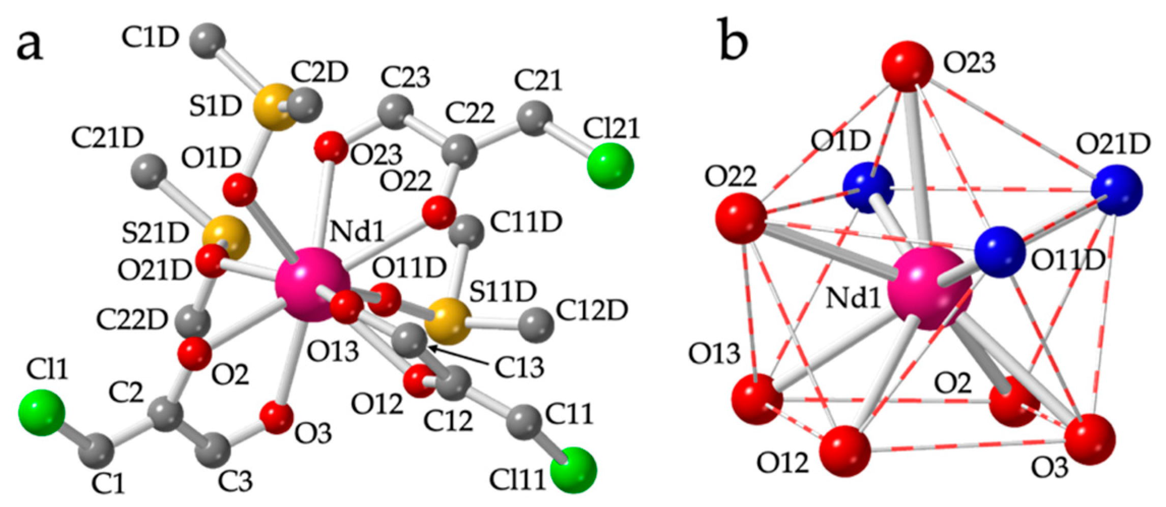
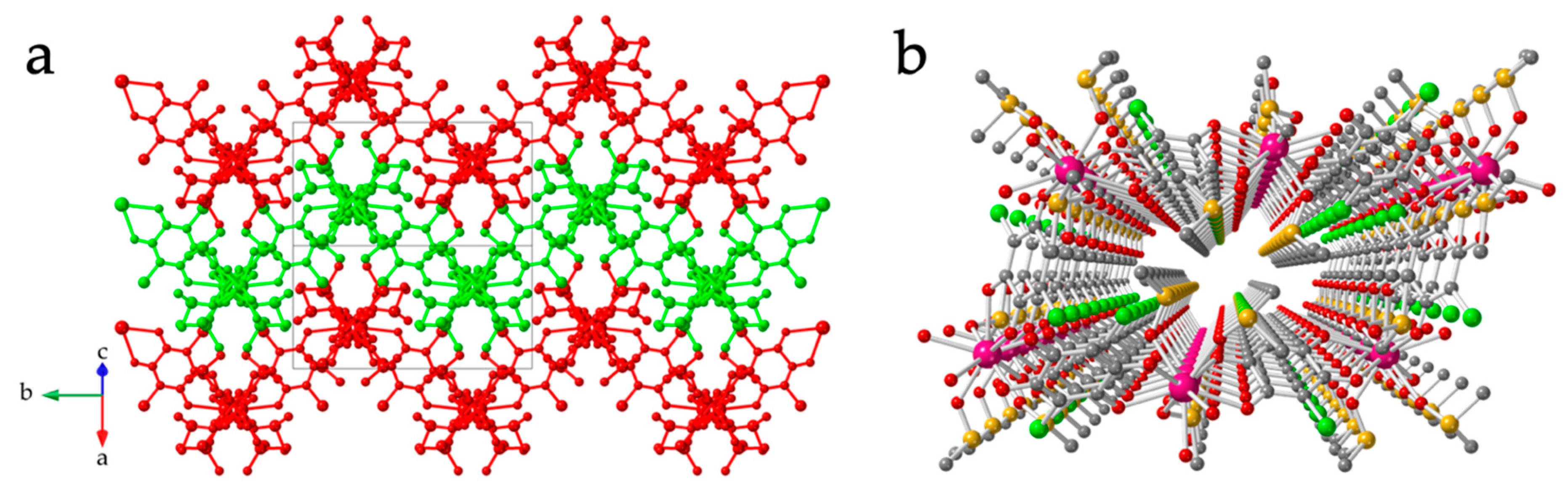
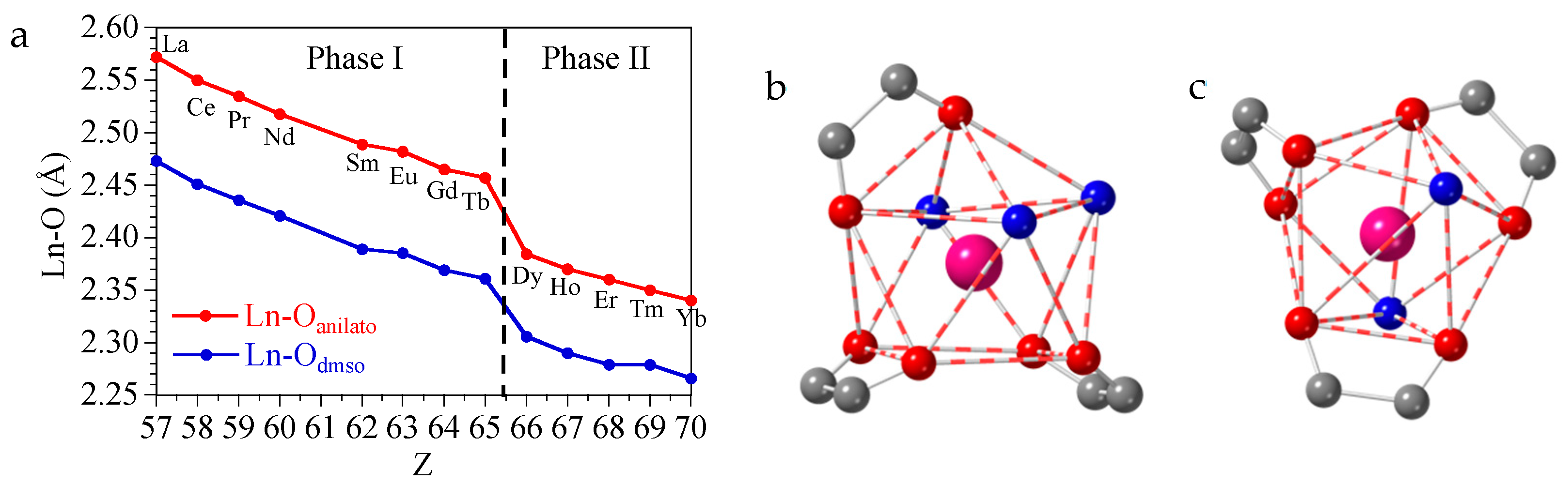
3.2. Crystal Structure of [Ln2(C6O4Cl2)3(dmso)6] with Ln = La(1), Ce(2), Pr(3), Nd(4), Sm(5), Eu(6), Gd(7) and Tb(8)
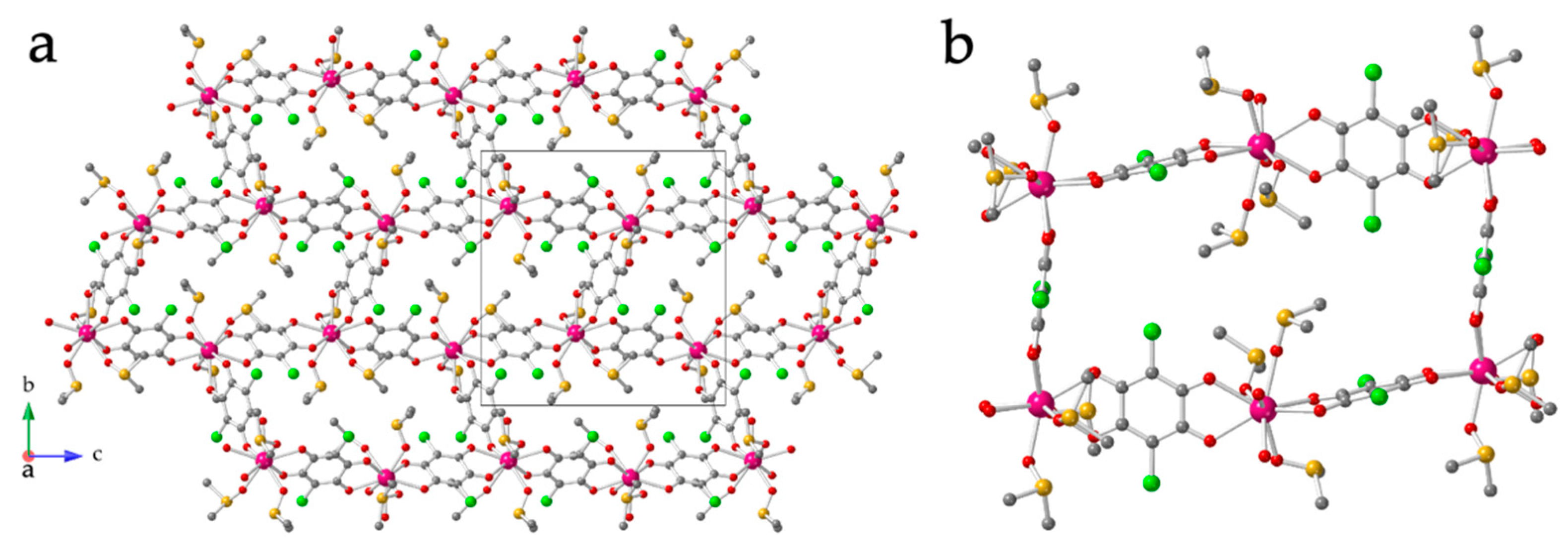
3.3. Crystal Structure of [Ln2(C6O4Cl2)3(dmso)4]·2dmso·2H2O with Ln = Dy(9), Ho(10), Er(11), Tm(12) and Yb(13)
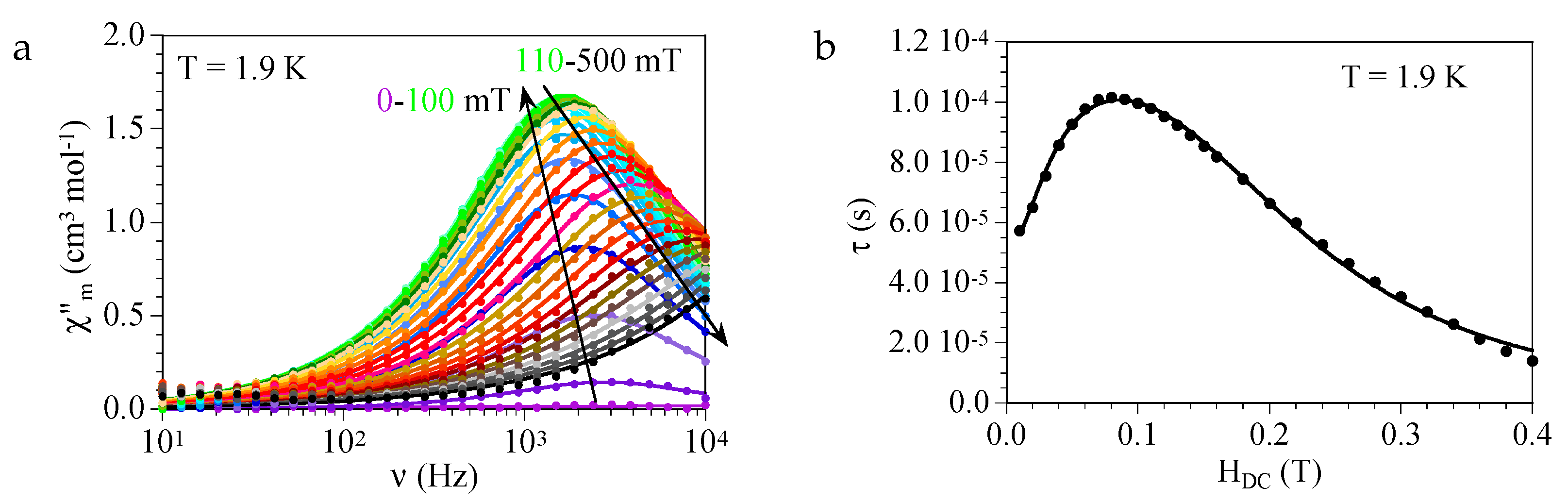
3.4. Magnetic Properties of Compounds 1–13
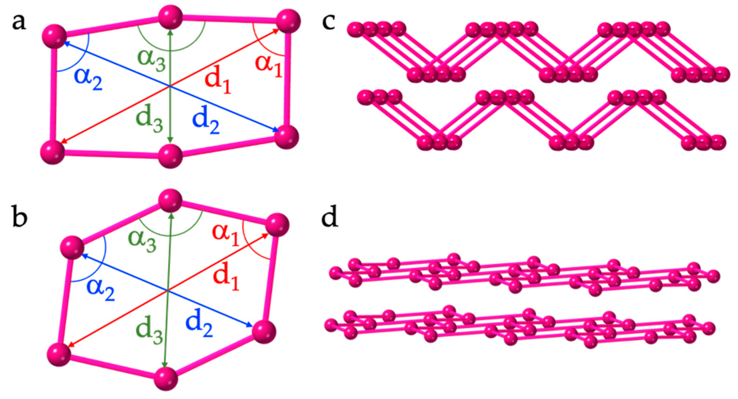
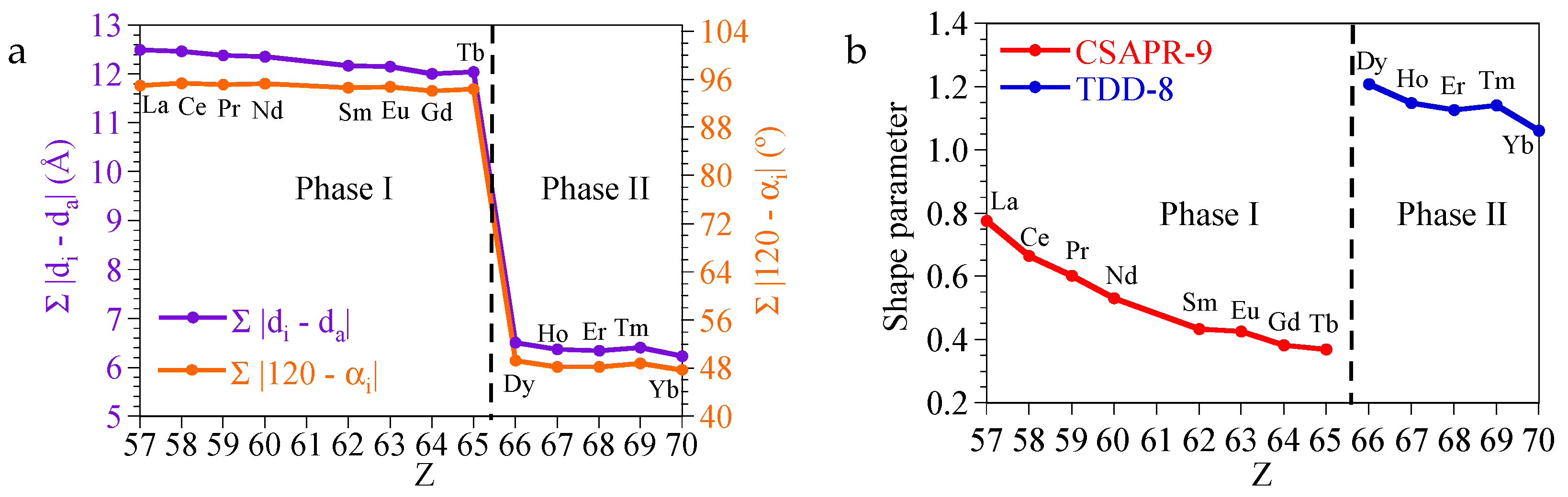
4. Discussion
5. Conclusions
Supplementary Materials
Author Contributions
Funding
Data Availability Statement
Conflicts of Interest
References
- Batten, S.R.; Champness, N.R.; Chen, X.; Garcia-Martinez, J.; Kitagawa, S.; Öhrström, L.; O’Keeffe, M.; Suh, M.P.; Reedijk, J. Terminology of metal–organic Frameworks and Coordination Polymers (IUPAC Recommendations 2013). Pure Appl. Chem. 2013, 85, 1715–1724. [Google Scholar] [CrossRef] [Green Version]
- Zhang, X.; Chen, Z.; Liu, X.; Hanna, S.L.; Wang, X.; Taheri-Ledari, R.; Maleki, A.; Li, P.; Farha, O.K. A Historical Overview of the Activation and Porosity of metal–organic Frameworks. Chem. Soc. Rev. 2020, 49, 7406–7427. [Google Scholar] [CrossRef] [PubMed]
- Zhou, H.C.; Long, J.R.; Yaghi, O.M. Introduction to Metal-Organic Frameworks. Chem. Rev. 2012, 112, 673–674. [Google Scholar] [CrossRef] [PubMed]
- Furukawa, H.; Cordova, K.E.; O’Keeffe, M.; Yaghi, O.M. The Chemistry and Applications of Metal-Organic Frameworks. Science 2013, 341, 1230444. [Google Scholar] [CrossRef] [PubMed] [Green Version]
- Shu-Na, Z.; Wang, G.; Poelman, D.; Van Der Voort, P. Metal Organic Frameworks Based Materials for Heterogeneous Photocatalysis. Molecules 2018, 23, 2947. [Google Scholar]
- Zhao, X.; Wang, Y.; Li, D.; Bu, X.; Feng, P. Metal–Organic Frameworks for Separation. Adv. Mater. 2018, 30, 1705189. [Google Scholar] [CrossRef]
- Canivet, J.; Fateeva, A.; Guo, Y.; Coasne, B.; Farrusseng, D. Water Adsorption in MOFs: Fundamentals and Applications. Chem. Soc. Rev. 2014, 43, 5594–5617. [Google Scholar] [CrossRef] [Green Version]
- Li, H.; Zhao, S.; Zang, S.; Li, J. Functional metal–organic Frameworks as Effective Sensors of Gases and Volatile Compounds. Chem. Soc. Rev. 2020, 49, 6364–6401. [Google Scholar] [CrossRef]
- Kreno, L.E.; Leong, K.; Farha, O.K.; Allendorf, M.; Van Duyne, R.P.; Hupp, J.T. Metal-Organic Framework Materials as Chemical Sensors. Chem. Rev. 2012, 112, 1105–1125. [Google Scholar] [CrossRef]
- Campbell, M.G.; Dinca, M. Metal-Organic Frameworks as Active Materials in Electronic Sensor Devices. Sensors 2017, 17, 1108. [Google Scholar] [CrossRef]
- Xie, L.S.; Skorupskii, G.; Dincă, M. Electrically Conductive Metal–Organic Frameworks. Chem. Rev. 2020, 120, 8536–8580. [Google Scholar] [CrossRef] [PubMed] [Green Version]
- Lim, D.; Kitagawa, H. Rational Strategies for Proton-Conductive metal–organic Frameworks. Chem. Soc. Rev. 2021, 50, 6349–6368. [Google Scholar] [CrossRef] [PubMed]
- Asadi, K.; van der Veen, M.A. Ferroelectricity in Metal–Organic Frameworks: Characterization and Mechanisms. Eur. J. Inorg. Chem. 2016, 2016, 4332–4344. [Google Scholar] [CrossRef] [Green Version]
- Kurmoo, M. Magnetic Metal-Organic Frameworks. Chem. Soc. Rev. 2009, 38, 1353–1379. [Google Scholar] [CrossRef] [PubMed]
- Li, B.; Wen, H.M.; Cui, Y.; Zhou, W.; Qian, G.; Chen, B. Emerging Multifunctional Metal-Organic Framework Materials. Adv. Mater. 2016, 28, 8819–8860. [Google Scholar] [CrossRef] [PubMed]
- Chakraborty, G.; Park, I.; Medishetty, R.; Vittal, J.J. Two-Dimensional Metal-Organic Framework Materials: Synthesis, Structures, Properties and Applications. Chem. Rev. 2021, 121, 3751–3891. [Google Scholar] [CrossRef]
- Wang, M.; Dong, R.; Feng, X. Two-Dimensional Conjugated metal–organic Frameworks (2D c-MOFs): Chemistry and Function for MOFtronics. Chem. Soc. Rev. 2021, 50, 2764–2793. [Google Scholar] [CrossRef]
- Benmansour, S.; Vallés-García, C.; Gómez-Claramunt, P.; Mínguez Espallargas, G.; Gómez-García, C.J. 2D and 3D Anilato-Based Heterometallic M(I)M(III) Lattices: The Missing Link. Inorg. Chem. 2015, 54, 5410–5418. [Google Scholar] [CrossRef]
- Atzori, M.; Artizzu, F.; Sessini, E.; Marchio, L.; Loche, D.; Serpe, A.; Deplano, P.; Concas, G.; Pop, F.; Avarvari, N.; et al. Halogen-Bonding in a New Family of Tris(Haloanilato)Metallate(Iii) Magnetic Molecular Building Blocks. Dalton Trans. 2014, 43, 7006–7019. [Google Scholar] [CrossRef]
- Benmansour, S.; Gómez-Claramunt, P.; Vallés-García, C.; Mínguez Espallargas, G.; Gómez García, C.J. Key Role of the Cation in the Crystallization of Chiral Tris(Anilato)Metalate Magnetic Anions. Cryst. Growth Des. 2016, 16, 518–526. [Google Scholar] [CrossRef]
- Kitagawa, S.; Kawata, S. Coordination Compounds of 1,4-Dihydroxybenzoquinone and its Homologues. Structures and Properties. Coord. Chem. Rev. 2002, 224, 11–34. [Google Scholar] [CrossRef]
- Abrahams, B.F.; Grannas, M.J.; Hudson, T.A.; Hughes, S.A.; Pranoto, N.H.; Robson, R. Synthesis, Structure and Host-Guest Properties of (Et4N)2[SnIVCaII(Chloranilate)4], a New Type of Robust Microporous Coordination Polymer with a 2D Square Grid Structure. Dalton Trans. 2011, 40, 12242–12247. [Google Scholar] [CrossRef] [PubMed]
- Benmansour, S.; Gómez-García, C.J. A Heterobimetallic Anionic 3,6-Connected 2D Coordination Polymer Based on Nitranilate as Ligand. Polymers 2016, 8, 89. [Google Scholar] [CrossRef] [PubMed] [Green Version]
- Mercuri, M.L.; Congiu, F.; Concas, G.; Sahadevan, S.A. Recent Advances on Anilato-Based Molecular Materials with Magnetic and/or Conducting Properties. Magnetochemistry 2017, 3, 17. [Google Scholar] [CrossRef] [Green Version]
- Benmansour, S.; Gómez-García, C.J. Lanthanoid-Anilato Complexes and Lattices. Magnetochemistry 2020, 6, 71. [Google Scholar] [CrossRef]
- Atzori, M.; Benmansour, S.; Mínguez Espallargas, G.; Clemente-León, M.; Abhervé, A.; Gómez-Claramunt, P.; Coronado, E.; Artizzu, F.; Sessini, E.; Deplano, P.; et al. A Family of Layered Chiral Porous Magnets Exhibiting Tunable Ordering Temperatures. Inorg. Chem. 2013, 52, 10031–10040. [Google Scholar] [CrossRef]
- Benmansour, S.; Gómez-García, C.J. Heterometallic Anilato-Based Layered Magnets. Gen. Chem. 2020, 6, 190033. [Google Scholar] [CrossRef]
- Benmansour, S.; López-Martínez, G.; Canet-Ferrer, J.; Gómez-García, C.J. A Family of Lanthanoid Dimers with Nitroanilato Bridges. Magnetochemistry 2016, 2, 32. [Google Scholar] [CrossRef] [Green Version]
- Benmansour, S.; Pérez-Herráez, I.; López-Martínez, G.; Gómez García, C.J. Solvent-Modulated Structures in Anilato-Based 2D Coordination Polymers. Polyhedron 2017, 135, 17–25. [Google Scholar] [CrossRef]
- Gómez-Claramunt, P.; Benmansour, S.; Hernández-Paredes, A.; Cerezo-Navarrete, C.; Rodríguez-Fernández, C.; Canet-Ferrer, J.; Cantarero, A.; Gómez-García, C.J. Tuning the Structure and Properties of Lanthanoid Coordination Polymers with an Asymmetric Anilato Ligand. Magnetochemistry 2018, 4, 6. [Google Scholar] [CrossRef] [Green Version]
- Benmansour, S.; Hernández-Paredes, A.; Gómez-García, C.J. Effect of the Lanthanoid-Size on the Structure of a Series of Lanthanoid-Anilato 2-D Lattices. J. Coord. Chem. 2018, 71, 845–863. [Google Scholar] [CrossRef]
- Benmansour, S.; Pérez-Herráez, I.; Cerezo-Navarrete, C.; López-Martínez, G.; Martínez Hernandez, C.; Gómez-García, C.J. Solvent-Modulation of the Structure and Dimensionality in Lanthanoid-Anilato Coordination Polymers. Dalton Trans. 2018, 47, 6729–6741. [Google Scholar] [CrossRef] [PubMed]
- Benmansour, S.; Hernández-Paredes, A.; Gómez-García, C.J. Two-Dimensional Magnetic Coordination Polymers Formed by Lanthanoids and Chlorocyananilato. Magnetochemistry 2018, 4, 58. [Google Scholar] [CrossRef] [Green Version]
- Hernández-Paredes, A.; Cerezo-Navarrete, C.; Gómez García, C.J.; Benmansour, S. Slow Relaxation in Doped Coordination Polymers and Dimers Based on Lanthanoids and Anilato Ligands. Polyhedron 2019, 170, 476–485. [Google Scholar] [CrossRef]
- Benmansour, S.; Hernández-Paredes, A.; Mondal, A.; López Martínez, G.; Canet-Ferrer, J.; Konar, S.; Gómez-García, C.J. Slow Relaxation of the Magnetization, Reversible Solvent Exchange and Luminescence in 2D Anilato-Based Frameworks. Chem. Commun. 2020, 56, 9862–9865. [Google Scholar] [CrossRef]
- Mondal, A.; Roy, S.; Konar, S. Remarkable Energy Barrier for Magnetization Reversal in 3D and 2D Dysprosium-Chloranilate-Based Coordination Polymers. Chem. Eur. J. 2020, 26, 8774–8783. [Google Scholar] [CrossRef]
- Benmansour, S.; Hernández-Paredes, A.; Bayona-Andrés, M.; Gómez-García, C.J. Slow Relaxation of the Magnetization in Anilato-Based Dy(III) 2D Lattices. Molecules 2021, 26, 1190. [Google Scholar] [CrossRef]
- Abrahams, B.F.; Coleiro, J.; Ha, K.; Hoskins, B.F.; Orchard, S.D.; Robson, R. Dihydroxybenzoquinone and Chloranilic Acid Derivatives of Rare Earth Metals. J. Chem. Soc. Dalton Trans. 2002, 1586–1594. [Google Scholar] [CrossRef]
- Diaz-Torres, R.; Alvarez, S. Coordinating Ability of Anions and Solvents Towards Transition Metals and Lanthanides. Dalton Trans. 2011, 40, 10742–10750. [Google Scholar] [CrossRef]
- Alvarez, S. Coordinating Ability of Anions, Solvents, Amino Acids, and Gases towards Alkaline and Alkaline-Earth Elements, Transition Metals, and Lanthanides. Chem. Eur. J. 2020, 26, 8663. [Google Scholar] [CrossRef]
- Bain, G.A.; Berry, J.F. Diamagnetic Corrections and Pascal’s Constants. J. Chem. Educ. 2008, 85, 532–536. [Google Scholar] [CrossRef]
- Oxford Diffraction Crysalispro. 2004. 171.33.55. Available online: https://www.rigaku.com/products/crystallography/crysalis (accessed on 10 February 2022).
- Altomare, A.; Burla, M.C.; Camalli, M.; Cascarano, G.L.; Giacovazzo, C.; Guagliardi, A.; Moliterni, A.G.G.; Polidori, G.; Spagna, R. SIR97: A New Tool for Crystal Structure Determination and Refinement. J. Appl. Cryst. 1999, 32, 115–119. [Google Scholar] [CrossRef]
- Sheldrick, G.M. Crystal Structure Refinement with SHELXL. Acta Cryst. C 2015, 71, 3–8. [Google Scholar] [CrossRef]
- Farrugia, L.J. WinGX and ORTEP for Windows: An Update. J. Appl. Cryst. 2012, 45, 849–854. [Google Scholar] [CrossRef]
- Álvarez, S. Distortion Pathways of Transition Metal Coordination Polyhedra Induced by Chelating Topology. Chem. Rev. 2015, 115, 13447–13483. [Google Scholar] [CrossRef] [PubMed] [Green Version]
- Riley, P.E.; Haddad, S.F.; Raymond, K.N. Preparation of Praseodymium(III) Chloranilate and the Crystal Structures of Pr2(C6Cl2O4)3·8C2H5OH and Na3[C6H2O(OH)(SO3)2]·H2O. Inorg. Chem. 1983, 22, 3090–3096. [Google Scholar] [CrossRef]
- Sorace, L.; Gatteschi, D. Electronic Structure and Magnetic Properties of Lanthanide Molecular Complexes; Layfield, R.A., Murugesu, M., Eds.; Wiley-VCH Verlag GmbH & Co.: Weinheim, Germany, 2015; Volume 1, pp. 1–25. [Google Scholar]
- Dey, A.; Kalita, P.; Chandrasekhar, V. Lanthanide(III)-Based Single-Ion Magnets. ACS Omega 2018, 3, 9462–9475. [Google Scholar] [CrossRef] [PubMed]
- Demir, S.; Zadrozny, J.M.; Long, J.R. Large Spin-Relaxation Barriers for the Low-Symmetry Organolanthanide Complexes Cp*2Ln(BPh4)] (Cp*=pentamethylcyclopentadienyl; Ln=Tb, Dy). Chem. Eur. J. 2014, 20, 9524–9529. [Google Scholar] [CrossRef]


| HDC (mT) | A (K−1) | τ0 (s) | Ueff (K) |
|---|---|---|---|
| 20 | 7.8(3) × 103 | 2(1) × 10−8 | 21(2) |
| 50 | 5.9(1) × 103 | 1.1(3) × 10−8 | 23(1) |
| 100 | 4.9(1) × 103 | 0.9(2) × 10−8 | 24(1) |
Publisher’s Note: MDPI stays neutral with regard to jurisdictional claims in published maps and institutional affiliations. |
© 2022 by the authors. Licensee MDPI, Basel, Switzerland. This article is an open access article distributed under the terms and conditions of the Creative Commons Attribution (CC BY) license (https://creativecommons.org/licenses/by/4.0/).
Share and Cite
Benmansour, S.; Gómez-García, C.J.; Hernández-Paredes, A. The Complete Series of Lanthanoid-Chloranilato Lattices with Dimethylsulfoxide: Role of the Lanthanoid Size on the Coordination Number and Crystal Structure. Crystals 2022, 12, 261. https://doi.org/10.3390/cryst12020261
Benmansour S, Gómez-García CJ, Hernández-Paredes A. The Complete Series of Lanthanoid-Chloranilato Lattices with Dimethylsulfoxide: Role of the Lanthanoid Size on the Coordination Number and Crystal Structure. Crystals. 2022; 12(2):261. https://doi.org/10.3390/cryst12020261
Chicago/Turabian StyleBenmansour, Samia, Carlos J. Gómez-García, and Antonio Hernández-Paredes. 2022. "The Complete Series of Lanthanoid-Chloranilato Lattices with Dimethylsulfoxide: Role of the Lanthanoid Size on the Coordination Number and Crystal Structure" Crystals 12, no. 2: 261. https://doi.org/10.3390/cryst12020261
APA StyleBenmansour, S., Gómez-García, C. J., & Hernández-Paredes, A. (2022). The Complete Series of Lanthanoid-Chloranilato Lattices with Dimethylsulfoxide: Role of the Lanthanoid Size on the Coordination Number and Crystal Structure. Crystals, 12(2), 261. https://doi.org/10.3390/cryst12020261