Abstract
Different from previous works which have focused on broadening the bandwidth, we propose an electromagnetic absorber with a medium and tailored bandwidth absorption, which avoids the unnecessary absorption caused by the too-wide bandwidth. Nevertheless, absorption is extremely high to be more than 99% and 97% for the normal and even oblique (45°) incidence, respectively, in a tailored frequency range of 5.8 ± 0.25 GHz even for both TE and TM polarization. This means the absorber is insensitive to the polarization of incident electromagnetic wave. Furthermore, it is flexible, since the main portion of sample is soft and flexible polyimide. The same properties are also realized in a range of 10 ± 0.5 GHz through adjusting the parameters of structure. The center frequencies of 5.8 and 10 GHz are very useful in our daily life, and the cost of absorber is relative low. Therefore, we believe the absorber can be used in many practical fields such as vehicle high-pass applications and radars.
1. Introduction
Metamaterials as artificial material open a door to the versatile and advanced applications of electromagnetic (EM) wave, due to their unique double-negative refractive properties [1]. Generally speaking, they are fabricated so that the unit cells are arranged periodically, and the scale of unit cell is smaller than the wavelength of incident wave. The frequency range of adjusted EM wave is from MHz to the visible light, which depends on mainly the structure and the material properties. The applications of metamaterials include superlens [2], cloaking [3], antenna [4], enhanced transmitter (ET) [5], metamaterial absorber (MA) [6], and so on.
Metamaterial absorber was proposed firstly by Landy et al. in 2008 [6]. Inspired by the work, various kinds of MA with narrow bandwidth have been suggested, such as MA with multi-peaks [7,8], polarization insensitivity [9,10], wide range of incident angle [11,12], in the early days of relevant research. Nowadays most of the researches focus on the flexible and broadband absorbers through the superimposition of many absorption peaks [13,14,15], by adding lumped elements [16,17,18], by employing liquid [19,20], by using resistive sheet [21,22] and conductive fiber [23], and so on. It is meaningful to introduce Kim’s work, which investigated the ultra-broadband MA based on resistive sheets [21]. The key role of resistive sheet, employed in their study, is its connection of each absorption peak, and the bandwidth of absorption seems boundary-less.
Metamaterial–based ET is also a potential application field. The theory related to ET can be traced back to the Bethe’s theory which expounds that the transmission efficiency of a sub-wavelength aperture scales as (r/λ)4, where r is the radius of hole, λ is the wavelength of incident EM wave [24]. It means that the transmission is very low if the size of hole is much smaller than the wavelength. However, in 1988 Ebbesen et al. demonstrated that the transmission of arrays of sub-wavelength holes was enhanced remarkably [25]. The Investigation on ET has not been carried out in the range of microwave frequency as well as the optical-frequency range. Aydin et al. proposed a method for the ET effect based on metamaterial in 2009 [5]. The ET effect occurred by setting a metamaterial element which could localize the EM wave, in front of the hole. Their work has inspired new ways in designing the frequency-selective surface making use of metamaterials.
It is necessary to explain that the aim of our design is not to improve a single property of the MA, but to maintain a very high absorption at an oblique incidence of both transverse-electric (TE) and transverse-magnetic (TM) polarization in a certain medium range of frequency. At the same time, the fabrication should be simple and at a low cost to accommodate many possible requirements of the practical applications. In order to avoid unnecessarily-excessive absorption, as shown in ref. [21], the MA should have an appropriate and tailored medium-bandwidth which is the best for the proper application purpose. This can be achieved, for example, with a resistive layer and meta-pattern layer for certain specific applications. By considering the practicality, the MA is better to be flexible and the central frequency of absorption is designed, for instance, at 5.8 GHz. The absorption maintains above 99% at the normal incidence throughout a frequency range of 5.55–6.05 GHz. Furthermore, it shows over 97% all the way during an incident angle range of 0–45° for both TE and TM polarization. By a slight modification, in other words, by adjusting the structural parameters in the same shape, this can be also employed for a frequency range of 9.5–10.5 GHz.
2. Materials, Structure and Methods
The unit-cell structure consisted of 5 layers, as shown in Figure 1, which are copper meta-pattern, polyimide 1, resistive sheet, polyimide 2, and continuous copper layers in order. The parameters of materials, that is, the conductivity of copper, the resistance of resistive sheet, the dielectric constant and loss tangent of polyimide were 5.8 × 10⁸ S/m, 540 Ω/sq, 3.5 and 0.0024, respectively. The thickness of copper layer, resistive sheet and polyimide 2 was set to be 0.035, 0.1 and 0.5 mm, respectively. Other structural parameters comprise the periodicity of unit cell, the width and length of bars, and the thickness of polyimide 1, which were optimized to be 12.5, 0.3, 4.5, and 1.7 mm. The resistive sheet played a role of broadening the absorption band, in other words, making several small seed peaks of absorption merge. The absorption was calculated by formula A = 1 – R – T = 1 – |S11|2 – |S12|2, where the R = |S11|2, T = |S12|2 and A denote the reflection, transmission and absorption, respectively. Since the transmission is negligible because of blocking by the continuous metallic layer, A = 1 − |S11|2.
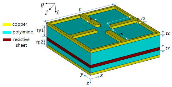
Figure 1.
Schematic of the unit cell of MA.
We employed the relative impedance to analyze the absorption. The relative impedance is described as [1]
where and are the effective permeability and permittivity, respectively.
Simulations were carried out with CST software throughout our work. We set the periodic boundary condition in the x-y plane and open in the z direction.
3. Results and Discussion
Figure 2 shows the absorption spectra of TE and TM polarization. The results show that the absorption over 99% is realized in a frequency range of 5.5–6.1 GHz, to be the most appropriate for an application around 5.8 GHz, as shown in Figure 2a. The absorption turns out to be insensitive to the polarization of incident EM wave as shown in Figure 2b, since the structure is symmetrical. As the incident angle increases, the absorption band becomes narrower, in general, and the maximum of absorption comes to be lower for both TE and TM polarization (Figure 2c,d). On the other hand, the range of frequency, corresponding to an absorption over 97%, is 5.54–6.2 GHz and 5.25–6.05 GHz for the TE and TM polarization, respectively, during the incident angle changes from 0 to 45°. Therefore, the effective range of frequency (ERF), which is the intersection of bandwidth (for absorption ≥99% at an incident angle of 0) and bandwidth (for absorption ≥97% at an incident angle of 45°), is revealed to be 5.54–6.05 GHz. This satisfies the requirement of 5.8 ± 0.25 GHz for over 97% of absorption in both polarizations and at any incident angle of 45° or less, as shown in Figure 2c,d. These requirements are relevant to some beneficial application in the field of intelligent transportation system. Furthermore, the maximum of absorption is still above 90% even at an large incidence of 60°.
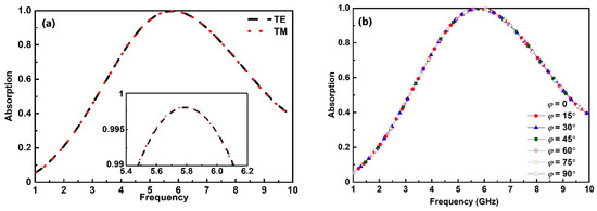
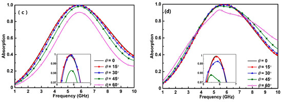
Figure 2.
Absorption spectra of (a) the TE and TM polarization at the normal incidence, (b) at various polarization angles, and (c) at various incident angles of (c) the TE and (d) TM polarization.
The real and imaginary parts of normalized impedance are presented in Figure 3a, and as expected the normalized real and imaginary parts of impedance turns out to be close to 1 and 0, respectively, around 5.8 GHz. This means the impedance matching, which is related to the occurrence of strong absorption. Since the resistive sheet is known to play a key role for a high and broad absorption, we investigated the absorption and the normalized impedance of structure without metallic meta-pattern and polyimide-1 layers. According to Figure 3b, the resistive sheet is noticed to induce a broadband absorption, and the absorption is around 97% for the normal incidence. The average value of normalized real and imaginary parts of impedance is close to 1 and 0, respectively.
Figure 3.
(a) Normalized real and imaginary part of the impedance of MA. (b) Absorption of the TE and TM polarization, and normalized real and imaginary parts of the impedance of MA without meta-pattern and polyimide-1 layers. (c) Equivalent circuit model of the MA.
An equivalent circuit model of the MA was made, as in Figure 3c. The intrinsic impedances of free space and polyimide are and , respectively. and are the relative permeability and permittivity of polyimide, and are those in vacuum. The input impedance () should satisfy the following equation.
and the and can be expressed as
where
here, is the velocity of EM wave in vacuum. According to Equations (1)–(4), the relationships between R, L and C can be described as below. The structure was elucidated more, based on this model.
and
To figure out the effect of metallic meta-pattern layer on the properties relevant to absorption, we performed a comparative analysis between ET and MA structures. The ET one does not include the resistive sheet. From Figure 4a, it is found that two spectra very close, but the spectrum of transmission is broader than that of absorption, and the center frequency of absorption peak is slightly lower than that of the transmission peak. This is because of a weak magnetic resonance induced between meta-pattern layer and resistive sheet in case of the MA structure, as shown in the middle figures of Figure 4b. The induced surface currents on the meta-pattern and resistive layer is revealed to be antiparallel, when we compare between middle left and bottom left figures in Figure 4b. As well-known, the resonance frequency of equivalent resonant circuit is described as , where L denotes the inductance, and C the capacitance. With respect to the ET structure, the MA structure includes antiparallel surface currents, which leads to the resonance shift to lower frequency.
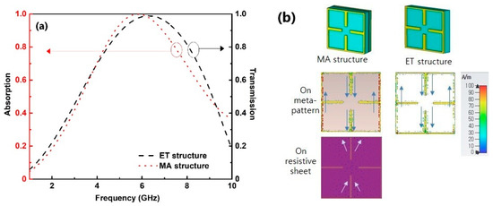
Figure 4.
(a) Absorption and transmission spectra of the ET and MA structures. (b) Distributions of the surface current (in arrow) and magnetic field (in dot) in the ET and MA structures.
We provide two effective methods to adjust the bandwidth of absorption, which is important for a specific application. One is to adjust the length m of bars of the meta-pattern, as shown in Figure 5a, and the other is to control the thickness of polyimide-1 layer, as in Figure 6. According to the results in Figure 5a, as the bar length m is longer, the bandwidth becomes narrower. The distribution of power-loss density for different lengths of bar are presented in Figure 5b. The shorter length of bar results in the dispersion of power-loss density on the surface of resistive sheet.
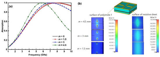
Figure 5.
(a) Absorption spectra of the MA structure according to m. (b) Distribution of the power-loss density on the surfaces of polyimide 1 and resistive sheet.
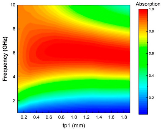
Figure 6.
Absorption spectra by varying the thickness of polyimide 1.
There are two kinds of resonance mechanism existing in the structure. The first is the EM resonance which include the electric resonance on the surface of ET structure and the magnetic resonance between ET one and resistive sheet. The second is the multi-reflection between ET structure and resistive layer. In addition, all affect each other. According to the distributions of surface current and power-loss density (Figure 5b), the electric resonance plays more important role than the other two effects. As the thickness of polyimide 1 increases, the magnetic resonance comes to be weaker and the multi-reflection is enhanced, which leads to the narrower peak of absorption, as shown in Figure 6. Q-factor can be described as . A high value of Q–factor signifies the sharpness of a peak. Conversely, the low value means a flat peak [26]. Either increasing the thickness of polyimide 1 or the length of bar induces the enhanced inductance, and then the Q-factor is reduced, which explains the bandwidth narrowing.
Many ways have been proposed to obtain the EM-wave MAs with a certain bandwidth of absorption. In the early stage of the relevant researches, the MAs with a specific bandwidth have been obtained by combining multi-absorption bands. These can be obtained in two types. one is to employ metallic patterned patches with the same shape but different sizes as the meta-pattern layer, and the other is to stack metallic/dielectric multilayers [27,28]. The disadvantage of the first kind is that the absorption peaks are depressed in the absorption band, even at normal incidence let alone the case of oblique one. For case of the second type, the fabrication is so complicated.
Nowadays many absorbers have been proposed with broadband and wide incidence angle, such as in references [29,30,31,32,33,34,35]. However, the superior performance of these absorbers is limited only in some special aspect or under some conditions. For example, the absorption was maintained at 90% for both TE and TM polarization when the incident angle changed from 0 to 60, however, it was only for a single peak of absorption. For case of the MA with broadband, shown as reference [30], the absorption was over 90% in a frequency range of 8–20 GHz for the normal incidence of both TE and TM mode. Nevertheless, since the spectra were uneven, as the incident angle increased the spectra of absorption rose up, and went down for the TM and TE polarization, respectively. Therefore, it is hard to find the MA with the superior performance in a certain frequency range for both TE and TM one. Table 1 show more examples. It should be noted that some data shown in Table 1 are approximate values obtained from figures in references.

Table 1.
Comparison of the performance of our MA with relevant MAs.
Furthermore, we develop another MA which works in a different practical frequency range of 10 ± 0.5 GHz through maintain the shape but adjusting the structural parameters: p = 9.5, m = 2.2, and tp1 = 1.1 mm. This frequency range is also important for microwave communication to be applied to ship radars and so on. For case of the normal incidence, the absorption turns out to be over 99% in 9.27–10.7 GHz, which is not too broad but tailored for the application, in both TE and TM mode (see Figure 7). Even at an incident angle of 45°, the absorption is maintained to be over 97% in a frequency range of 9.26–10.63 and 8.77–10.87 GHz for the TE and TM polarization, respectively. Therefore, we devised the MA showing the high standards of performance in many aspects in a tailor-made frequency range of 9.26–10.63 GHz.
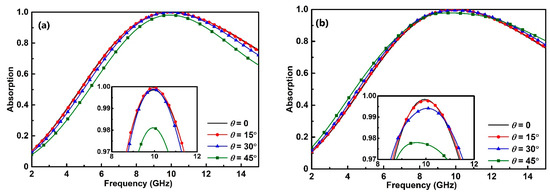
Figure 7.
Absorption spectra around 10 GHz for the (a) TE and (b) TM polarization according to different incident angles.
Figure 8 presents the most-important experimental spectra at an incident angle of 45° in the TE mode, on the MAs for (a) 5.8 and (b) 10 GHz. In addition, the experimental setup is shown in Figure 8c. The reflection spectra were measured in a microwave anechoic chamber. Two standard-gain horn antennas were used as the transmitting and the receiving antennas, which were connected to a Hewlett Packard E8362B network analyzer. The spatial positions and angles of the horn antenna and the sample were determined with the basic distance measurement tools which included the laser. In order to minimize the near-field effect, the distance of horn antenna and sample was far enough and the radiation of EM wave was sufficient. It was necessary to employ a high-conductivity metal plate (such as a copper plate) for testing the prefect reflection of EM wave before the formal measurement. When we compare those with the corresponding simulated ones [Figure 2c and Figure 7a for 5.8 and 10 GHz, respectively], the absorption in Figure 8a indicate 95.2% at 5.55 GHz, 98.5% at 5.8 GHz, and 97% at 6.05 GHz. At the same time, in Figure 8b 98% at 9.5 GHz, 98.1% at 10 GHz, and 96.1% at 10.5 GHz. Both experimental absorption values at 5.8 at 10 GHz turn out to be over 97%, which are nearly coincident with the simulation. The experimental absorption at one of the border frequencies is slightly lower than the corresponding simulation. This might be due to the minor manufacturing inaccuracies in sample preparation.
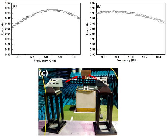
Figure 8.
Absorption spectra of the MAs for (a) 5.8 and (b) 10 GHz. (c) Experimental setup.
4. Conclusions
We propose a tailored medium-bandwidth MA with superior performance was designed and investigated systematically. This absorber meets the multiple strict conditions of characteristics simultaneously. The absorption is above 99% and 97% for the normal incidence and an oblique incidence of 45°, respectively, in a frequency range of 5.55 to 6.05 GHz for both TE and TM polarization. The MA is flexible. and fabricated easily and cheap. The idea is extended even for 10 ± 0.5 GHz. These can be applied immediately to the practical applications of intelligent transportation, ship radars and so on.
Author Contributions
H.Z. and Y.-P.L. conceived ideas. The electromagnetic simulations and calculations were carried out by H.Z. and L.C. H.Z. and Y.-P.L. analyzed the data and wrote the article. Y.-P.L. provided important suggestions and made corrections. All of the authors discussed and commented on the manuscript. All authors have read and agreed to the published version of the manuscript.
Funding
This research is funded by the Korea Evaluation Institute of Industrial Technology (Project No. 20016179).
Institutional Review Board Statement
Not applicable.
Informed Consent Statement
Not applicable.
Data Availability Statement
The data presented in this paper are available on request from the corresponding author.
Acknowledgments
We appreciate J. H. Jin at Korea Electromagnetic Research for his helping in the measure-ment.
Conflicts of Interest
The authors declare no conflict of interest.
References
- Smith, D.R.; Vier, D.C. Electromagnetic parameter retrieval from inhomogeneous metamaterials. Phys. Rev. E 2005, 71, 036617. [Google Scholar] [CrossRef] [PubMed] [Green Version]
- Fang, N.; Zhang, X. Imaging Properties of a Metamaterial Superlens. Nanometamaterials 2002, 27, 225–228. [Google Scholar]
- Schurig, D.; Mock, J.J.; Justice, B.J.; Cummer, S.A.; Pendry, J.B.; Starr, A.F.; Smith, D.R. Metamaterial Electromagnetic Cloak at Microwave Frequencies. Science 2006, 314, 977–980. [Google Scholar] [CrossRef] [PubMed] [Green Version]
- Dong, Y.; Itoh, T. Metamaterial-Based Antennas. Proc. IEEE 2012, 100, 2271–2285. [Google Scholar] [CrossRef]
- Aydin, K.; Cakmak, A.O.; Sahin, L.; Li, Z.; Bilotti, F.; Vegni, L.; Ozbay, E. Split-Ring-Resonator-Coupled Enhanced Transmission through a Single Subwavelength Aperture. Phys. Rev. Lett. 2009, 102, 013904. [Google Scholar] [CrossRef] [Green Version]
- Landy, N.I.; Sajuyigbe, S.; Mock, J.J.; Smith, D.R.; Padilla, W.J. Perfect Metamaterial Absorber. Phys. Rev. Lett. 2008, 100, 207402. [Google Scholar] [CrossRef]
- Park, J.W.; Tuong, P.V.; Rhee, J.Y.; Kim, K.W.; Jang, W.H.; Choi, E.H.; Chen, L.Y.; Lee, Y.P. Multi-band metamaterial absorber based on the arrangement of donut-type resonators. Opt. Express 2013, 21, 9691–9702. [Google Scholar] [CrossRef]
- Cheng, Y.Z.; Cheng, Z.Z.; Mao, X.S.; Gong, R.Z. Ultra-Thin Multi-Band Polarization-Insensitive Microwave Metamaterial Absorber Based on Multiple-Order Responses Using a Single Resonator Structure. Materials 2017, 10, 1241. [Google Scholar] [CrossRef] [Green Version]
- Lee, D.; Hwang, J.G.; Lim, D.; Hara, T.; Lim, S. Incident Angle- and Polarization Insensitive Metamaterial Absorber using Circular Sectors. Sci. Rep. 2016, 6, 27155. [Google Scholar] [CrossRef] [Green Version]
- Hoa, N.T.; Tung, P.D.; Dung, N.D.; Nguyen, H.; Tuan, T.S. Numerical study of a wide incident angle- and polarisation-insensitive microwave metamaterial absorber based on a symmetric flower structure. AIP Adv. 2019, 9, 065318. [Google Scholar] [CrossRef] [Green Version]
- Amiri, M.; Tofigh, F.; Shariati, N.; Lipman, J.; Abolhasan, M. Wide-angle metamaterial absorber with highly insensitive absorption for TE and TM modes. Sci. Rep. 2020, 10, 13638. [Google Scholar] [CrossRef] [PubMed]
- Bilal, R.M.H.; Baqir, M.A.; Hameed, M.; Naqvi, S.A.; Ali, M.M. Triangular metallic ring-shaped broadband polarization-insensitive and wide-angle metamaterial absorber for the visible regime. J. Opt. Soc. Am. A 2022, 39, 136. [Google Scholar] [CrossRef]
- Dao, R.; Kong, X.; Zhang, H.; Tian, X. A Tunable Ultra-Broadband Metamaterial Absorber with Multilayered Structure. Plasmonics 2020, 15, 169–175. [Google Scholar] [CrossRef]
- Rahmanzadeh, M.; Rajabalipanah, H.; Abdolali, A. Multilayer graphene-based metasurfaces: Robust design method for extremely broadband, wide-angle, and polarization-insensitive terahertz absorbers. Appl. Opt. 2018, 57, 959–968. [Google Scholar] [CrossRef]
- Huang, L.; Chowdhury, D.R.; Ramani, S.; Reiten, M.T.; Luo, S.; Taylor, A.; Cheng, H. Experimental demonstration of terahertz metamaterial absorbers with a broad and flat high absorption band. Opt. Lett. 2012, 37, 154–156. [Google Scholar] [CrossRef] [Green Version]
- Badri, K.S.L.A. Microwave metamaterial for broad-band perfect absorber applications. Mater. Today Proc. 2021, 42, 2835. [Google Scholar] [CrossRef]
- Wen, K.; Han, T.; Lu, H.; Luo, W.; Zhang, L.; Chen, H.; Liang, D.; Deng, L. Experimental demonstration of an ultra-thin radar-infrared bi-stealth rasorber. Opt. Express 2021, 29, 8872–8879. [Google Scholar] [CrossRef]
- Kong, X.; Xu, J.; Mo, J.; Liu, S. Broadband and conformal metamaterial absorber. Front. Optoelectron. 2017, 10, 124–131. [Google Scholar] [CrossRef]
- Yoo, Y.; Ju, S.; Park, S.Y.; Kim, Y.J.; Bong, J.; Lim, T.; Kim, K.W.; Rhee, J.Y.; Lee, Y.P. Metamaterial Absorber for Electromagnetic Waves in Periodic Water Droplets. Sci. Rep. 2015, 5, 14018. [Google Scholar] [CrossRef] [Green Version]
- Shrekenhamer, D.; Chen, W.; Padilla, W.J. Liquid Crystal Tunable Metamaterial Perfect Absorber. Phys. Rev. Lett. 2013, 110, 177403. [Google Scholar] [CrossRef]
- Kim, Y.J.; Yoo, Y.J.; Hwang, J.S.; Lee, Y.P. Ultra-broadband microwave metamaterial absorber based on resistive sheets. J. Opt. 2017, 19, 015103. [Google Scholar] [CrossRef]
- Zhou, F.; Fu, Y.; Tan, R.; Zhou, J.; Chen, P. Broadband and wide-angle metamaterial absorber based on the hybrid of spoof surface plasmonic polariton structure and resistive metasurface. Opt. Express 2021, 29, 34735. [Google Scholar] [CrossRef] [PubMed]
- Kim, Y.J.; Hwang, J.S.; Khuyen, B.X.; Tung, B.S.; Kim, K.W.; Rhee, J.Y.; Chen, L.Y.; Lee, Y.P. Flexible ultrathin metamaterial absorber for wide frequency band, based on conductive fibers. Sci. Technol. Adv. Mater. 2018, 19, 714–717. [Google Scholar] [CrossRef]
- Bethe, H.A. Theory of diffraction by Small Holes. Phys. Rev. 1944, 66, 163. [Google Scholar] [CrossRef]
- Ebbesen, T.W.; Lezec, H.J.; Ghaemi, H.F.; Thio, T.; Wolff, P.A. Extraordinary optical transmission through sub-wavelength hole arrays. Nature 1998, 391, 667–669. [Google Scholar] [CrossRef]
- Gu, S.; Barrett, J.P.; Hand, T.H.; Popa, B.; Cummer, S.A. A broadband low-reflection metamaterial absorber. J. Appl. Phys. 2010, 108, 064913. [Google Scholar] [CrossRef] [Green Version]
- Viet, D.T.; Hien, N.T.; Tuong, P.V.; Minh, N.Q.; Trang, P.T.; Le, L.N.; Lee, Y.P.; Lam, V.D. Perfect absorber metamaterial: Peak, multi-peak. Opt. Commun. 2014, 322, 209–213. [Google Scholar] [CrossRef]
- Soheilifar, M.R. Design, fabrication and characterization of stacked layers planar broadband metamaterial absorber at microwave frequency. Int. J. Electron. Commun. 2015, 69, 126–132. [Google Scholar] [CrossRef]
- Hannan, S.; Islam, M.T.; Almutairi, A.F.; Faruque, M.R.I. Wide Bandwidth Angle- and Polarization-Insensitive Symmetric Metamaterial Absorber for X and Ku Band Applications. Sci. Rep. 2020, 10, 10338. [Google Scholar] [CrossRef]
- Xu, J.; Fan, Y.; Su, X.; Guo, J.; Zhu, J.; Fu, Q.; Zhang, F. Broadband and wide angle microwave absorption with optically transparent metamaterial. Opt. Mater. 2021, 113, 110852. [Google Scholar] [CrossRef]
- Yu, Y.; Sun, P.; Wang, Y.; Chen, Z. A new design for an ultra-wideband microwave metamaterial absorber. J. Phys. D Appl. Phys. 2021, 54, 295003. [Google Scholar] [CrossRef]
- Zhao, Y.; Li, S.; Jiang, Y.; Gu, C.; Liu, L.; Li, Z. An ultra-wideband and wide-angle optically transparent flexible microwave metamaterial absorber. J. Phys. D Appl. Phys. 2021, 54, 275101. [Google Scholar] [CrossRef]
- Long, L.V.; Khiem, N.S.; Tung, B.S.; Tung, N.T.; Giang, T.T.; Son, P.T.; Khuyen, B.X.; Lam, V.D.; Chen, L.; Zheng, H.; et al. Flexible Broadband Metamaterial Perfect Absorber Based on Graphene-Conductive Inks. Photonics 2021, 8, 440. [Google Scholar] [CrossRef]
- Wang, T.; He, H.H.; Ding, M.D.; Mao, J.B.; Sun, R.; Sheng, L. A flexible ultra-broadband metamaterial absorber working on whole K-bands with polarization-insensitive and wide-angle stability. Chin. Phys. B 2021. to be published. [Google Scholar] [CrossRef]
- Tirkey, M.M.; Gupta, N. Broadband Polarization-Insensitive Inkjet-Printed Conformal Metamaterial Absorber. IEEE Trans. Electromag. Compat. 2021, 63, 1829–1836. [Google Scholar] [CrossRef]
Publisher’s Note: MDPI stays neutral with regard to jurisdictional claims in published maps and institutional affiliations. |
© 2022 by the authors. Licensee MDPI, Basel, Switzerland. This article is an open access article distributed under the terms and conditions of the Creative Commons Attribution (CC BY) license (https://creativecommons.org/licenses/by/4.0/).