1. Introduction
Road construction was an important aspect of a nation’s infrastructure, economic and social development. To improve social and economic development, the construction of roads and quality road maintenance are necessary [
1]. The maintenance of roads was determined according to the climatic conditions of the region [
2]. So, for regions with a sharply continental climate, seasonal icing of the road surface was a big problem [
3].
Cement concrete and asphalt concrete pavements are widely used in road construction technology [
4]. Cement concrete roads (hereinafter concrete roads) have a great advantage over asphalt pavement: durability, strength, and resistance to frost heaving of the road base [
5]. One of the disadvantages of cement-concrete roads was the icing of their surface at negative temperatures, which affects traffic safety [
6]. Chemical reagents and salts capable of dissolving the ice crust are often used as a technical solution to eliminate this problem [
7]. However, the low resistance of concrete roads to aggressive media should be taken into account, which was formed by the interaction of chemicals and salts with water [
8]. As a result, the aggressiveness of the environment entails both the destruction of the road surface and causes corrosion of road vehicles [
9]. Treatment of the road surface with reagent requires periodic maintenance at each formation of icing. Given the frequent cyclicality of climatic conditions, this method has low efficiency and was not economically feasible [
10]. Similarly, in world practice, sand was used as an abrasive placed on the surface of icy roads, thereby increasing the traction of wheels with the ice crust [
11]. This method does not solve the whole problem, has a short-term effect, and requires constant maintenance.
The solution to this problem of icing on concrete roads was still relevant. It can be found in the use of impregnating compositions that do not require frequent maintenance but are capable of reducing ice formation or partially eliminating it [
12]. Then, in addition to the technological efficiency of the impregnation composition, the question of its economic efficiency becomes important [
13]. In this regard, the impregnation composition proposed in the article was made based on keratin-containing components obtained from animal waste [
14]. The composition provides an envelope for the pore structure of concrete, creating a tension difference layer, thereby preventing ice and concrete from becoming a single monolith. The ice breaks even with a small mechanical impact [
15]. Furthermore, the composition includes water-soluble polymers, which allows the great effect of the hydrophobic structure of concrete roads, protecting them from icing [
16].
Many impregnating compositions are currently used to protect cement concrete road pavements. These impregnation compositions are mainly used for water protection of cement concrete road pavements. These impregnation compositions also increase the resistance of the pavement to chemical reagents. One of such products was the Penetrative impregnation compound BRIT IC-1 (Riga, Latvia), Pavix (Richardsin, TX, USA), Sazi (Moscow, Russia), Strop-M (Almaty, Kazakhstan). The above products are used as waterproof and durability-enhancing on cement-based road pavement. Some of the first compounds of Silane and Siloxane were used as water-repellent and chemical resistant impregnating compositions for concrete which have been researched by scientists such as Rahman, Chamberlain, Al-Kheetan.
The research aims to evaluate the effectiveness of the proposed impregnation composition (ice-phobic coating) by testing iced concrete samples based on impact pulse.
The studies to assess the quality of the road surface have been carried out under laboratory conditions. The main evaluation parameter was the adhesion of the ice crust to the cement concrete road surface. As previously discussed, the nature of ice/concrete adhesion depends on the contact area of the two components (i.e., ice and concrete). The adhesion strength (adhesion resistance) of ice to concrete was the result of a conditional additive effect of the following factors: the first factor was the adhesion of ice to concrete as a material; the second factor was the ice entrapment (anchorage) in the pore (micro and macro) structure along the concrete surface [
17,
18]. The synergy effect was clearly observed here, i.e., if these factors are considered separately from each other, the effectiveness of their adhesion resistance was significantly reduced compared to the joint adhesion resistance where mutual influence was observed [
19]. Therefore, by excluding one of the factors (in our case, it was the first factor as ice adhesion), the effectiveness of the second factor—ice crust anchoring—can be significantly reduced [
2,
20].
2. Materials and Methods
Many experiments were done to analyse freezing effects on pavement structure, but one of the urgent problems was providing anti-icing methods for traffic safety [
21]. One method for providing anti-icing and technology of production, the impregnation composition, was presented below.
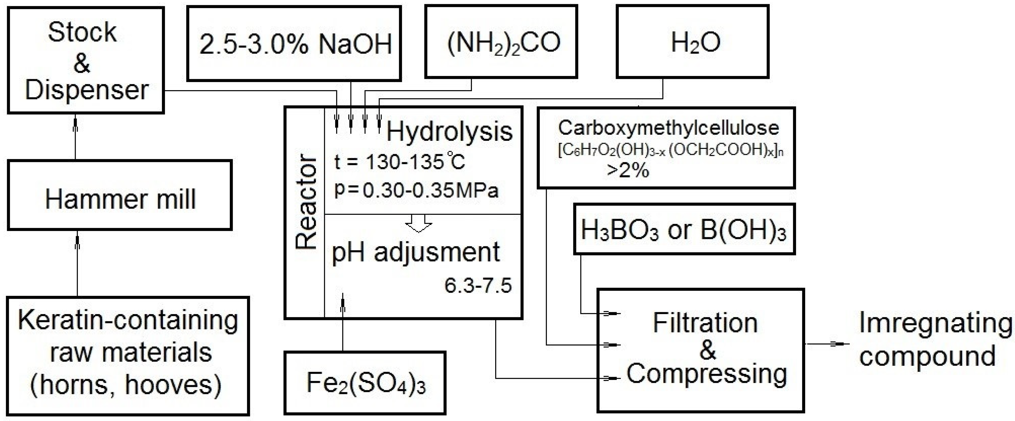
Figure 1 presents a process flowchart for producing the impregnation composition, which includes a hydrolysis procedure in an alkaline medium (to dissolve the keratin-containing raw material), followed by neutralising the alkaline medium. The production technology was based on the industrial production of keratin.
In the first stage of the study, it was important to analyse the effectiveness of the ice-coating and assess the nature of icing by comparing coated and uncoated samples. To this analyse, it was not necessary to simulate the computational loads perceived by the coating during vehicular traffic but rather to simulate computational schemes in which it was possible to evaluate the quality of ice adhesion to concrete. Therefore, design situations were adopted in which ice detachment from the icy pavement occurs. To this end, laboratory experiments were carried out with the application of vibration and shock loads to test specimens:
- –
Vibration impact on the sample on the vibration stand, vibration frequency up to 50 Hz and vibration amplitude up to 20 mm;
- –
Impact effect on the sample by free dropping the loading weight at the maximum height of 200 mm and the mass of the loading weight of 290 g.
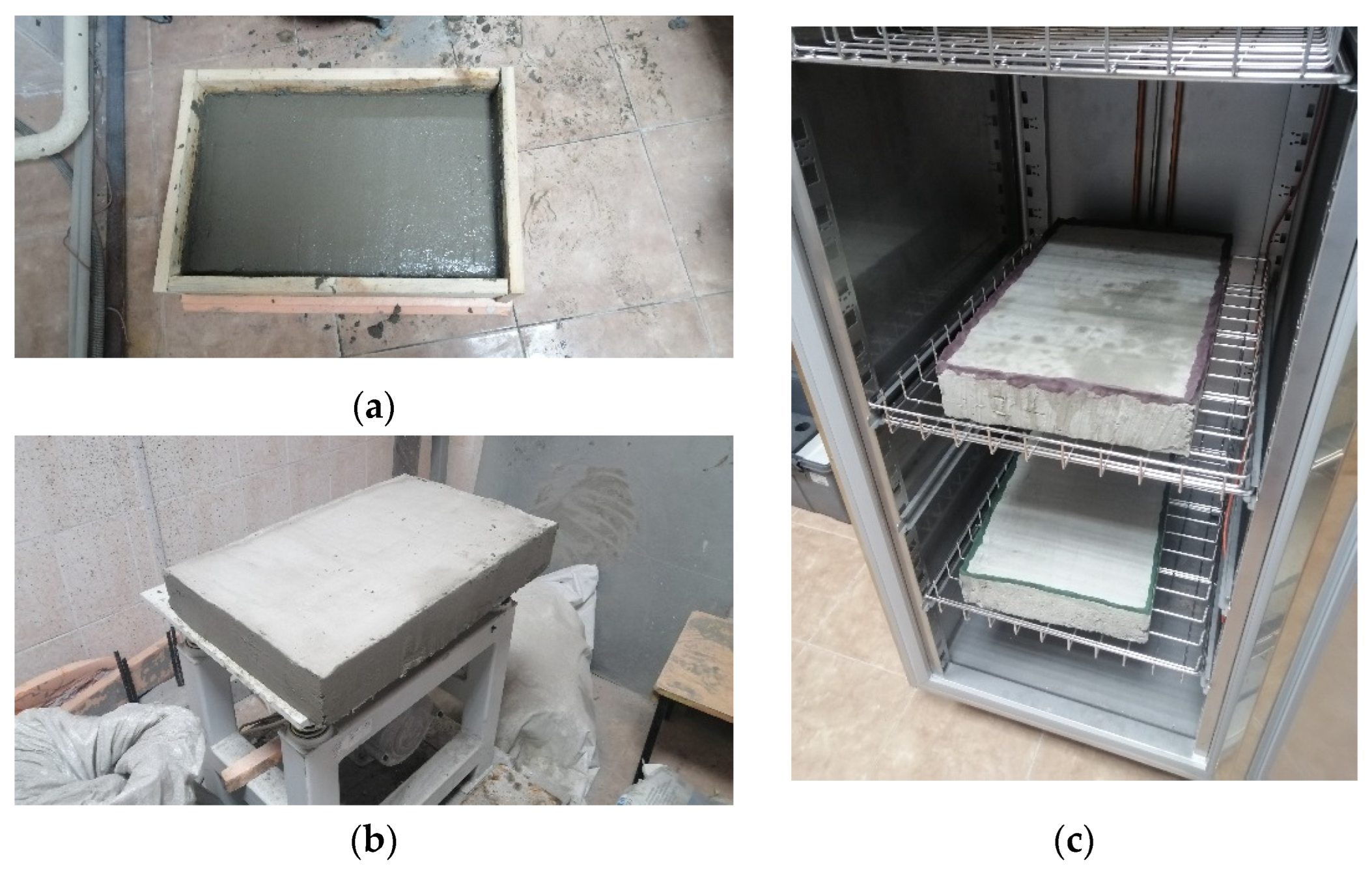
The tests were carried out for large specimens with height
h as 80 mm, width
b as 350 mm, and length
l as 550 mm (
Figure 2). The composition of the samples was as follows: 10 kg of cement, 30 kg of sand, 20 mL of post-alcohol bard, 5 mL of polyvinyl acetate (PVA), and water (the water-cement ratio was 0.3). After 28 days, the working surface of the first sample was impregnated with a 0.2–0.3 mm thick ice-impregnating compound; the surface of the second sample was not treated. A yellow dye was added to the impregnation composition for better surface visibility.
The samples were frozen in a Controls freezing chamber (Controls, Milan, Italy). Firstly, a rim was made along the contour of the working surface to retain the necessary amount of water on the sample’s surface. Secondly, only the working surface of the specimen was exposed to climatic influences for the purity of the experiment, while the remaining faces of the specimen (sides and bottom) were insulated with thermal insulation material (
Figure 2).
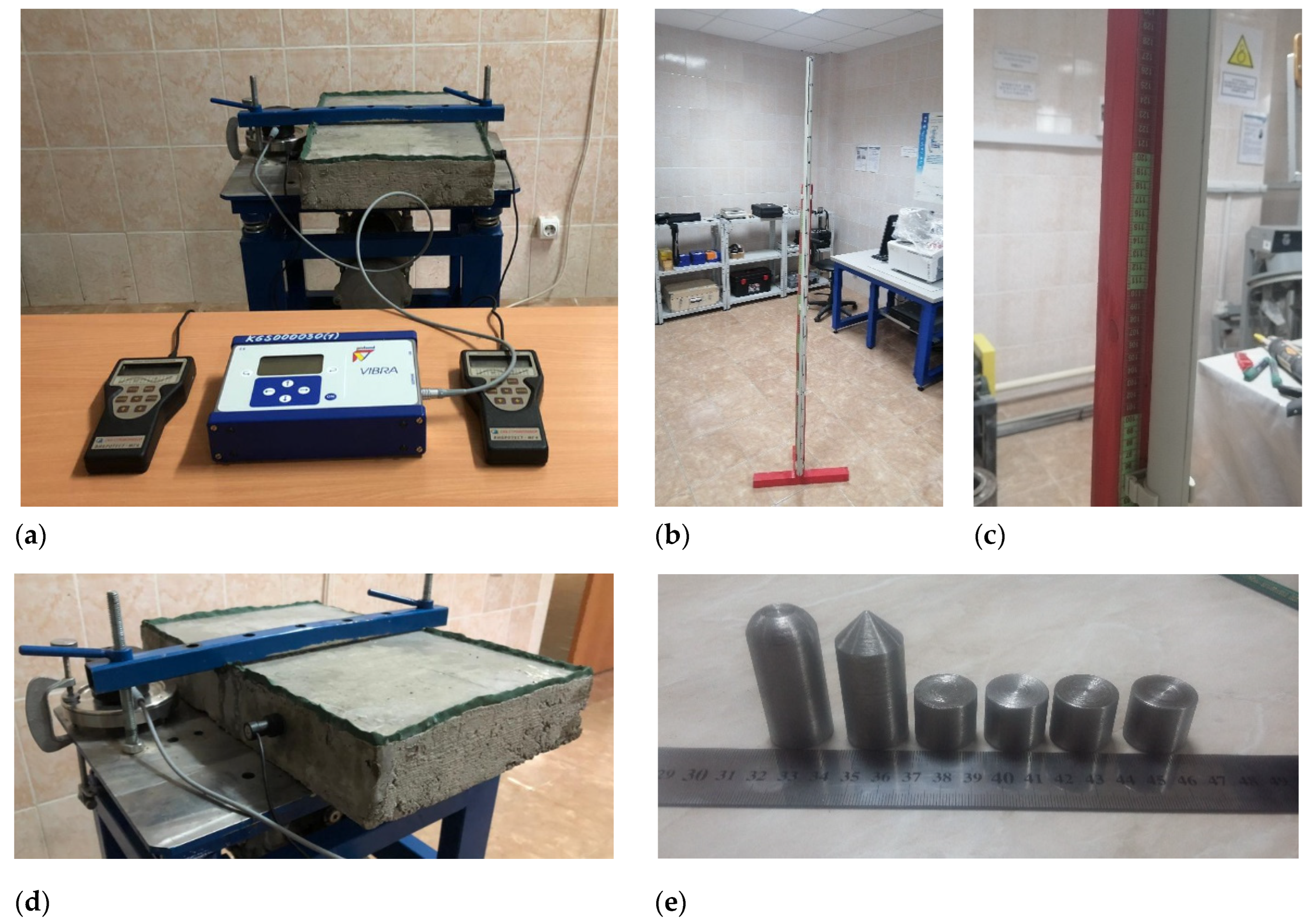
In the vibration test, the specimens were rigidly clamped to the surface of the vibration table in order to prevent any interference with the integrity of the specimens. Furthermore, to assess the effect of vibration loading on the ice crust, vibration transducers (Ltd. Stroypribor, Chelyabinsk, Russia) were used to record the frequency and amplitude of vibration (
Figure 3). The gauges were rigidly fixed to the concrete body and the surface of the vibration table. Profound Vibra+ vibration gauges (Profound, Waddinxveen, Netherlands) were fixed on the vibration table; Vibrotest-MG4.01 (Ltd. Stroypribor, Chelyabinsk, Russia) vibration gauges were fixed on both sides of the sample. The tests were conducted at the minimum vibration frequency (10 Hz), with incremental vibration amplitude of the bench. The increment of vibration load (amplitude) was carried out in stages, with an exposure time of 10 s for each stage, either to the collapse of the ice crust or the maximum power of the vibration test bench.
A stand for the impact test consisted of a measuring tape stand with a tubular guide element adjacent to it. The maximum height of the load-bearing was 2.0 metres. The loading element was made of solid cylindrical metal, and the impact part of the loading element was represented by a cone and a hemisphere (
Figure 3). The increase of impact energy was achieved by using an additional surcharge represented by cylindrical elements. The incremental impact energy was carried out either before the ice crust collapsed or before it was punctured pointwise or locally.
As an alternative experiment, thermal stress simulation was assumed to assess the quality of the ice crust. The effect of thermal cracking can be achieved elementarily by instantly injecting a hot liquid onto the icy surface. From the nature of the cracking, conclusions can be drawn as to the resistance of the icy coating. If there was no adhesion between the concrete and the ice crust, the degree of ice cracking will likely be greater compared to a specimen where concrete and ice adhesion was present.
In addition to the ice-cracking tests, the hydrophobic properties of the concrete were tested using the standard method of determining its water saturation (water permeability). In this case, ten standard cube-shaped specimens with an edge length of 10 cm were immersed in water until they reached a constant mass. Five specimens were treated with an ice-breaking compound on all outer faces; the other five were of the same qualitative and quantitative composition and were not surface-treated. The thickness of the ice-coating also corresponded to 0.2–0.3 mm.
3. Results and Discussion
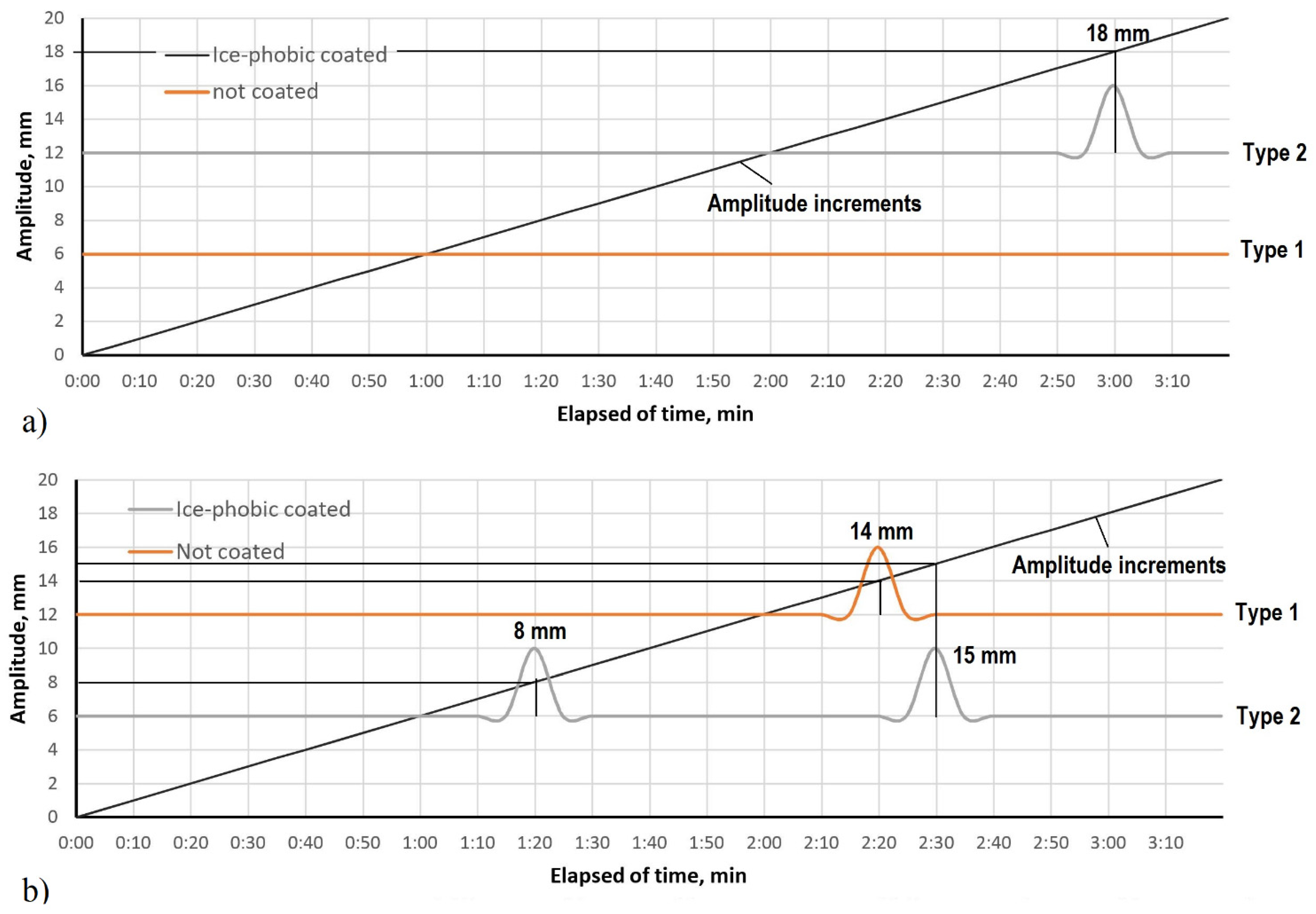
Figure 4 shows a graph presenting the results of the vibration test of the specimens. The tests were performed at a constant vibration frequency of the vibrating pad λ = 10 Hz, with incremental vibration amplitude.
Figure 4a shows the results of tests on the specimens without prior exposure to impact load, and
Figure 4b shows the results of tests on the specimens after exposure to impact load. The first peak on the graph shows the moment of the first discontinuity in the ice crust (the period of time when the first ice cracking or chipping was witnessed), and the second peak shows the moment of complete discontinuity (more than 80% of the area). Ice-coated (ice-phobic-coated) samples were referred to as Type 1, and uncoated (without ice-phobic coating) samples were referred to as Type 2.
According to the tests on specimens without prior shock loading, only ice-coated specimens showed a breach of integrity. The cracking of the ice crust was localised, with a slight spread of cracking as the vibration amplitude increased (
Figure 4). Initial discontinuity was observed after 180 s from the start of the experiment, which corresponds to a calibration amplitude of 18 mm. The uncoated specimen proved to be resistant to vibration loads (
Figure 4); no cracking or discontinuity was observed, indicating the ice crust’s relatively greater adhesion resistance to the uncoated concrete.
According to the test results of the pre-impacted specimens, integrity disruption was detected in both cases. The coated specimen’s primary discontinuity was observed 80 s after the start of the experiment, with an oscillation amplitude of 8 mm. In uncoated specimens, the primary fracture was observed at 140 s, with an amplitude of 14 mm. Since the primary cracking occurred due to impact loading, the first peak in the graph in
Figure 4b corresponds to the moment of further crack propagation. Furthermore, the ice-coated specimen showed delamination of the ice crust (
Figure 5), whereas the uncoated specimen showed no delamination of the ice crust from the concrete surface.
The above factors indicate that the uncoated specimens show greater adhesion of the ice crust to the concrete surface than the ice-coated specimens.
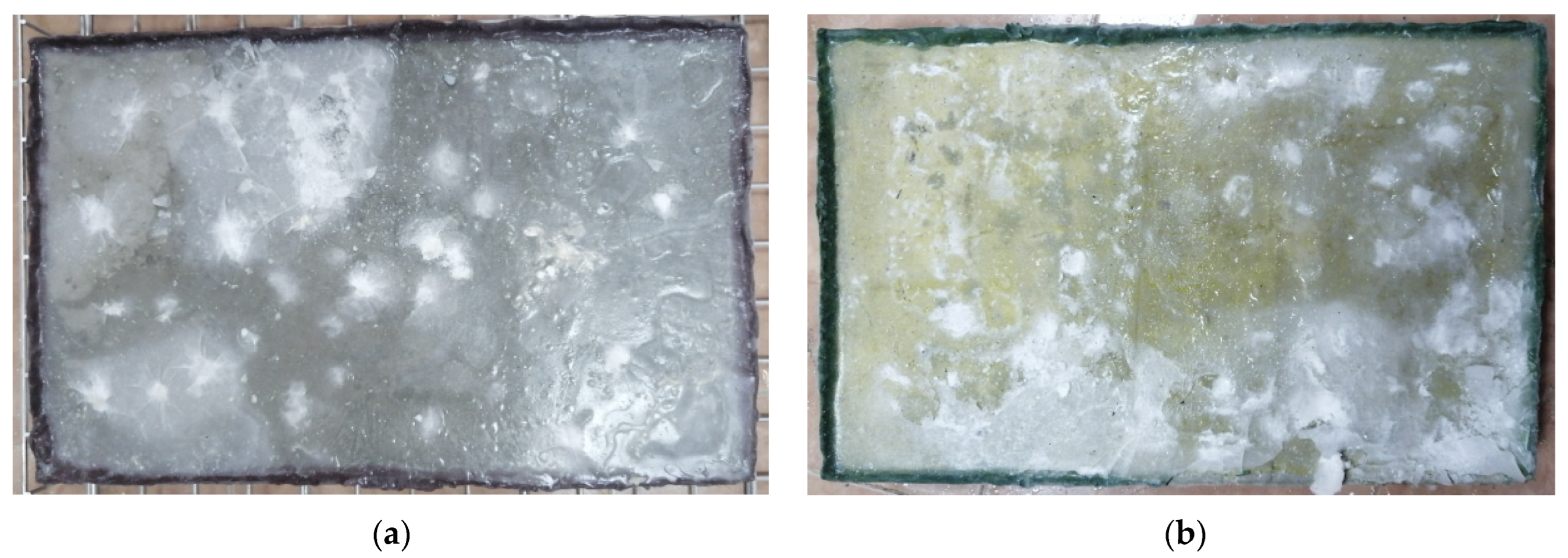
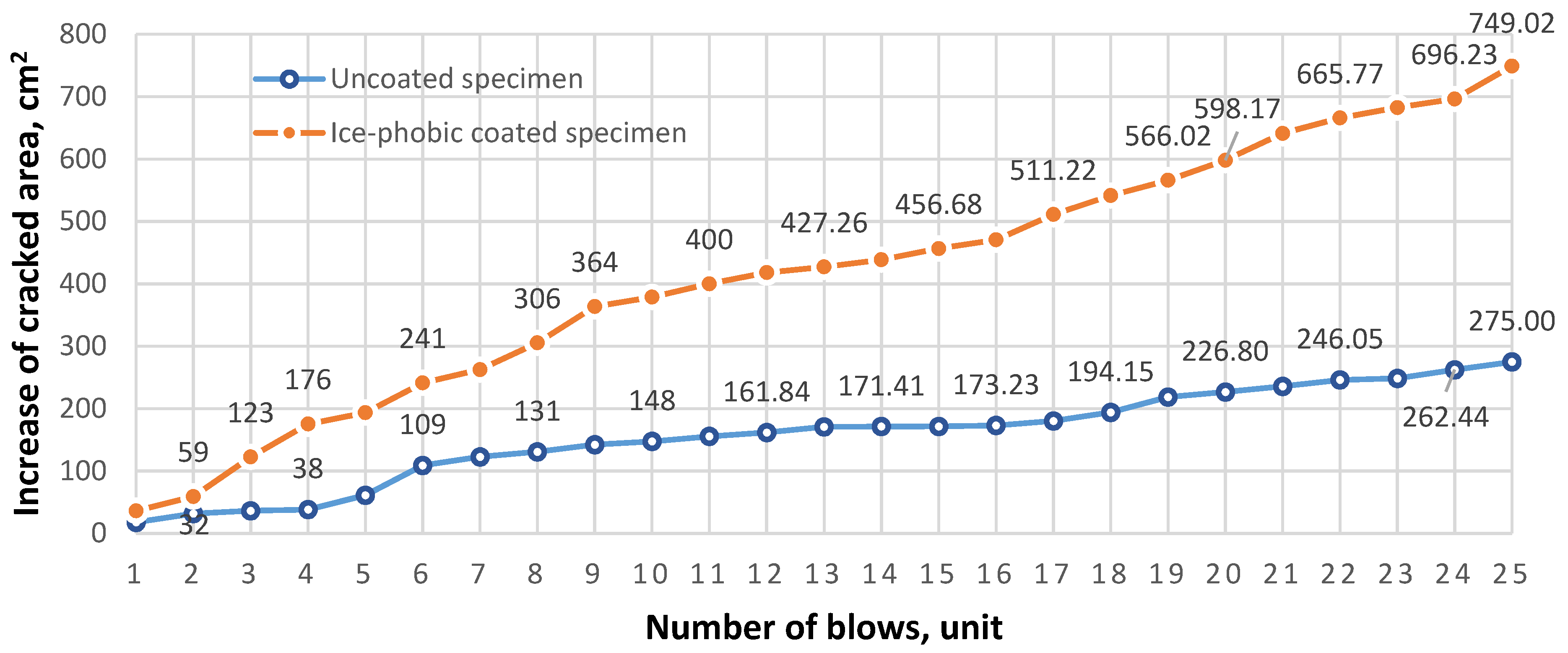
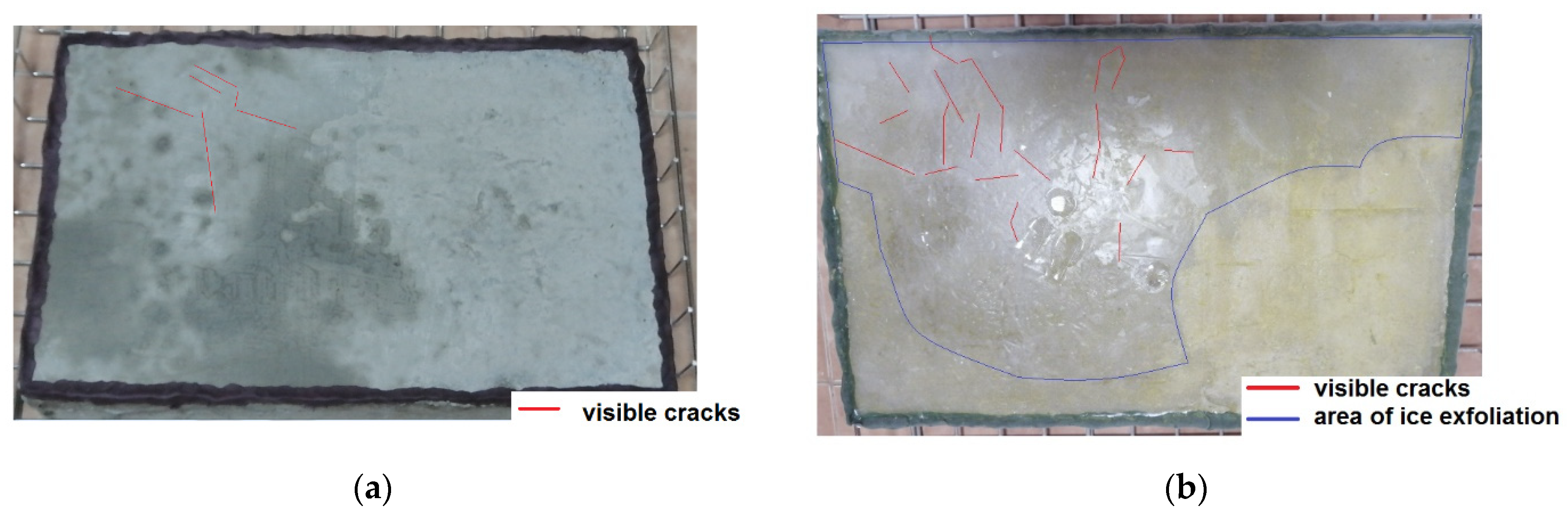
Figure 6 shows the test results of the specimens subjected to impact loading. A total mass of 700 g was dropped onto the ice surface of each sample from a height of 2.0 m. It was enough to perform 25 strokes on each sample to assess the ice crust resistance. According to visual inspection of the samples, the following tendency was revealed after the tests: crack propagation radius of uncoated samples was smaller than that of ice-coated samples. The cracks in uncoated specimens were concentrated near the point of dynamic impact and were local in nature, while the coated specimens had a larger radial crack distribution which was 1.7–2.1 times larger (compared to uncoated specimens). Furthermore, local chipping of the ice crust was observed in the coated samples, while no ice crust detachment was observed in the uncoated samples.
Figure 7 shows a graph of the crack propagation increment versus applied dynamic blows. According to the data, the total area of sample cracking using an ice-phobic coating was 749.02 cm
2, which was 38.91% of the total area of the ice crust. The cracking area of the sample without ice-phobic coating was 275.0 cm
2, which was 14.28% of the total area of the ice crust. Thus, the total cracking area of the ice-phobic coated specimen was 2.7 times that of the uncoated specimen.
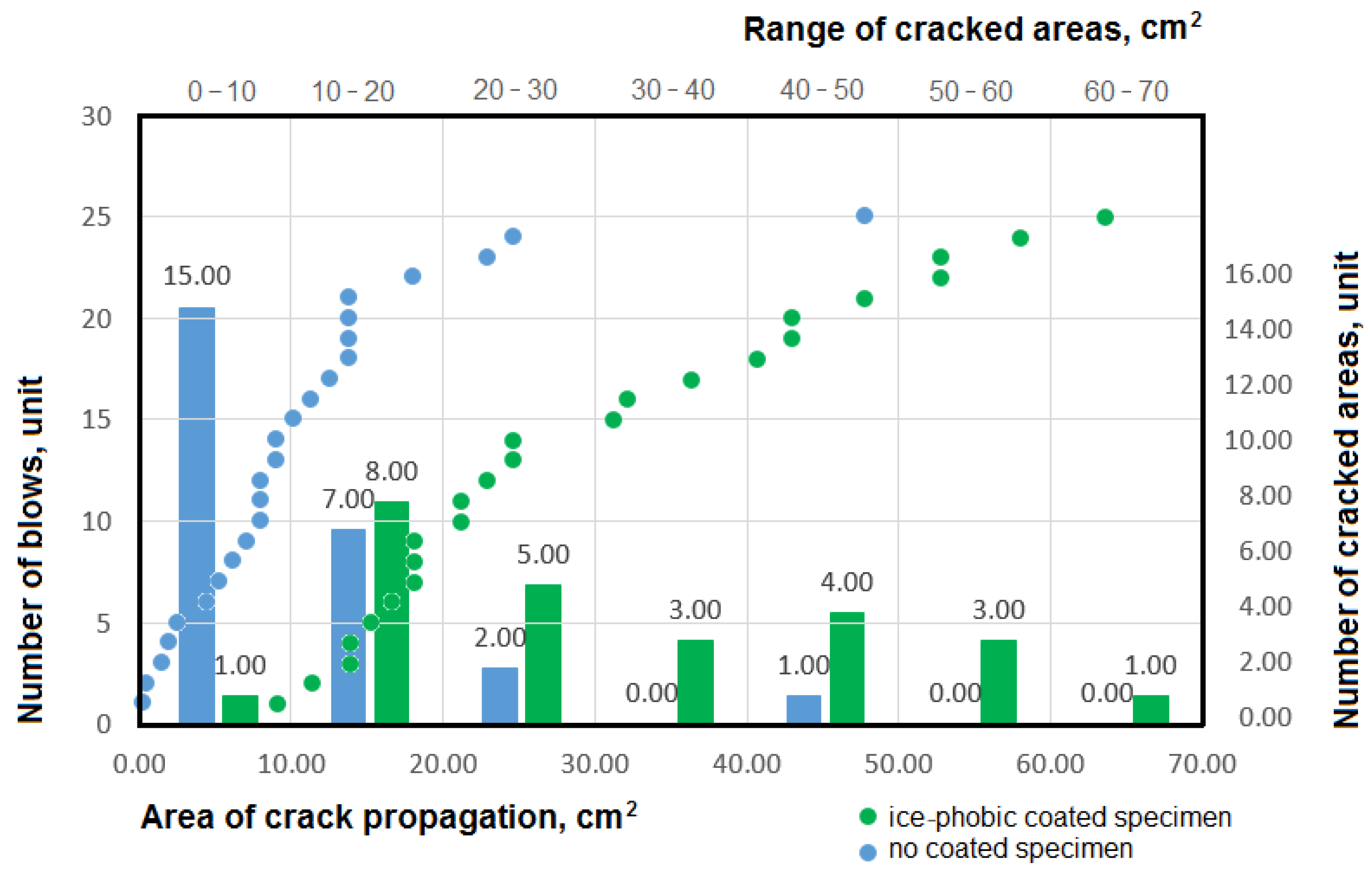
Figure 8 shows the partial values of the cracking areas of the individual blows. The relationship between the increase in total cracking area and the number of impacts was represented by discrete dots in the diagram (
x-axis at the bottom and
y-axis at the left). On the
x-axis, the individual cracking areas were grouped in ascending order, from the smallest area to the largest. Thus, each individual point corresponds to an individual cracking area. Histograms were also plotted, which describe the statistics of the individual values, i.e., their belonging to a certain range of cracking areas divisible by 10 cm
2 (the
x-axis at the top and the
y-axis at the right). According to the data, the maximum number of unique values of individual cracking areas of uncoated samples ranges from 0 to 10 cm
2, which corresponds to 60% of the total number of impacts. However, the maximum range of cracking area does not exceed 50 cm
2. The maximum number of unique area values for coated samples ranged from 10 to 20 cm
2. In other words, 32% of the total number of impacts have a cracking area not exceeding 20 cm
2. It should also be noted that the unique values of the cracking areas of the coated sample have a larger scattering of the data than the unique values of the uncoated sample. The maximum range of the cracking area of the coated sample was 70 cm
2.
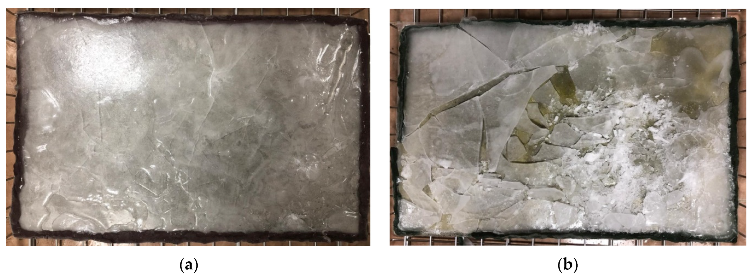
Figure 9 shows the results of the thermal stress simulation. On the icy surface of each sample, 300 g of hot water, which had a temperature of 100 °C, was injected after being kept in a freezer at −30 °C for 24 h. The wide temperature variation led to an instantaneous spread of thermal stress across the surface of the ice crust. Visual inspection of the specimens after the tests revealed the following: the surface of the uncoated specimens showed little local cracking of the ice crust, with no internal water penetration; the coated specimen showed widespread cracking of the ice crust, with micro and macro fractures. Furthermore, the coated specimen showed water intrusion, which resulted in delamination of the ice crust from the concrete coating. In total, more than 70% of the ice crust was observed to peel from the total surface area of the specimen. The test results confirmed the relatively low adhesion resistance of the coated specimens compared to the uncoated specimens.
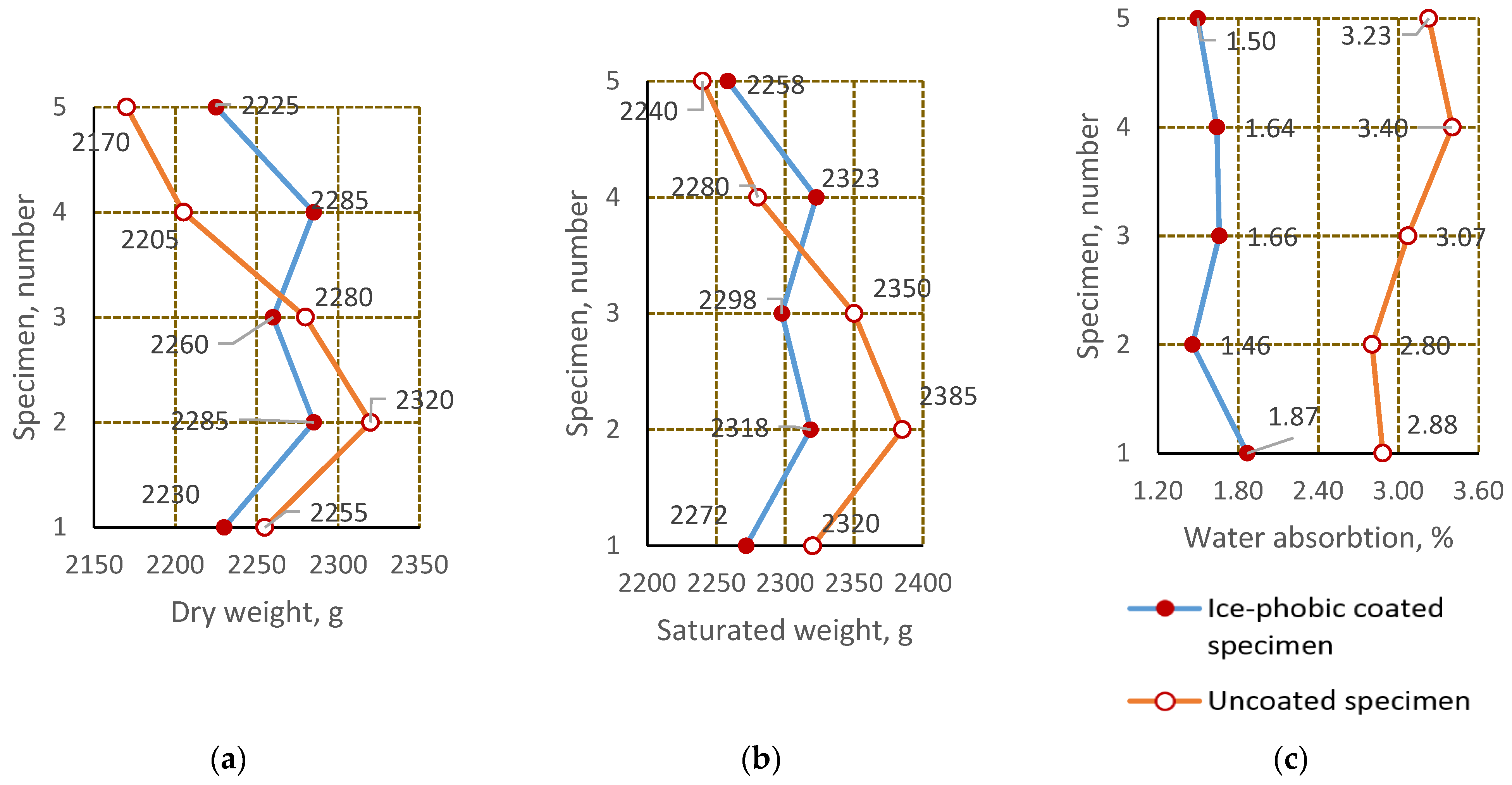
Figure 10 shows the results of the water absorption tests on the test specimens.
Figure 10a shows the average density in the dry state,
Figure 10b the average density in the wet state and
Figure 10c the average water absorption of the samples.
Particular weight values of ice-coated control specimens in dry conditions were varied from 2225 to 2285 g. The average weight value was 2257 g, which lies within the range of average concrete mass values. At the same time, the standard deviation of the individual values was 28.85, which indicates that the individual values of all samples were closely related to each other. The coefficient of variation does not exceed 1.27%, which means an insignificant deviation of particular values from the mean weight value. Particular weight values of ice-coated control samples in a water-saturated state varied from 2258 to 2323 g, with the average value being 2293 g. The standard deviation of particular values was 28.22, and the coefficient of variation was 1.23%, indicating close relation of particular values and their small deviations from the mean weight of samples in a water-saturated state. The water absorption of the samples ranged from 1.46 to 1.87%, with a mean value of 1.95, a standard deviation of 0.16 and a coefficient of variation of 9.9.
The partial mass values of the control specimens without ice-coating in a dry state vary between 2170 and 2320 g, and the average weight value was 2246 g, which also lies within the average weight of the concrete. The values obtained were also closely related, as the standard deviation was 59.51, and the coefficient of variation does not exceed 2.65%. The partial values in the water-saturated state range from 2240 to 2385 g; the average value was 2315 g. The standard deviation was 57.01, and the coefficient of variation was 2.46%, indicating that the individual values were closely related. The water absorption of the samples ranged from 2.80 to 3.40%, with a mean value of 3.07, a standard deviation of 0.24 and a coefficient of variation of 7.9.
Although the results of compared samples have a relatively small difference between them (2.07% in dry state and 0.92% in water-saturated state), the difference in water absorption was significant, amounting to 47.17%. This effect was also observed when analysing the spread of the curves in relation to each other, i.e., in the density diagrams, there was a relatively close relationship where there was even an overlap (due to the random order of partial values), whereas in the water absorption diagram the curves are distant from each other and, moreover, the pattern of identical curvature of the two curves indicates a certain pattern of influence of ice coverage on the water absorption capacity of the material.
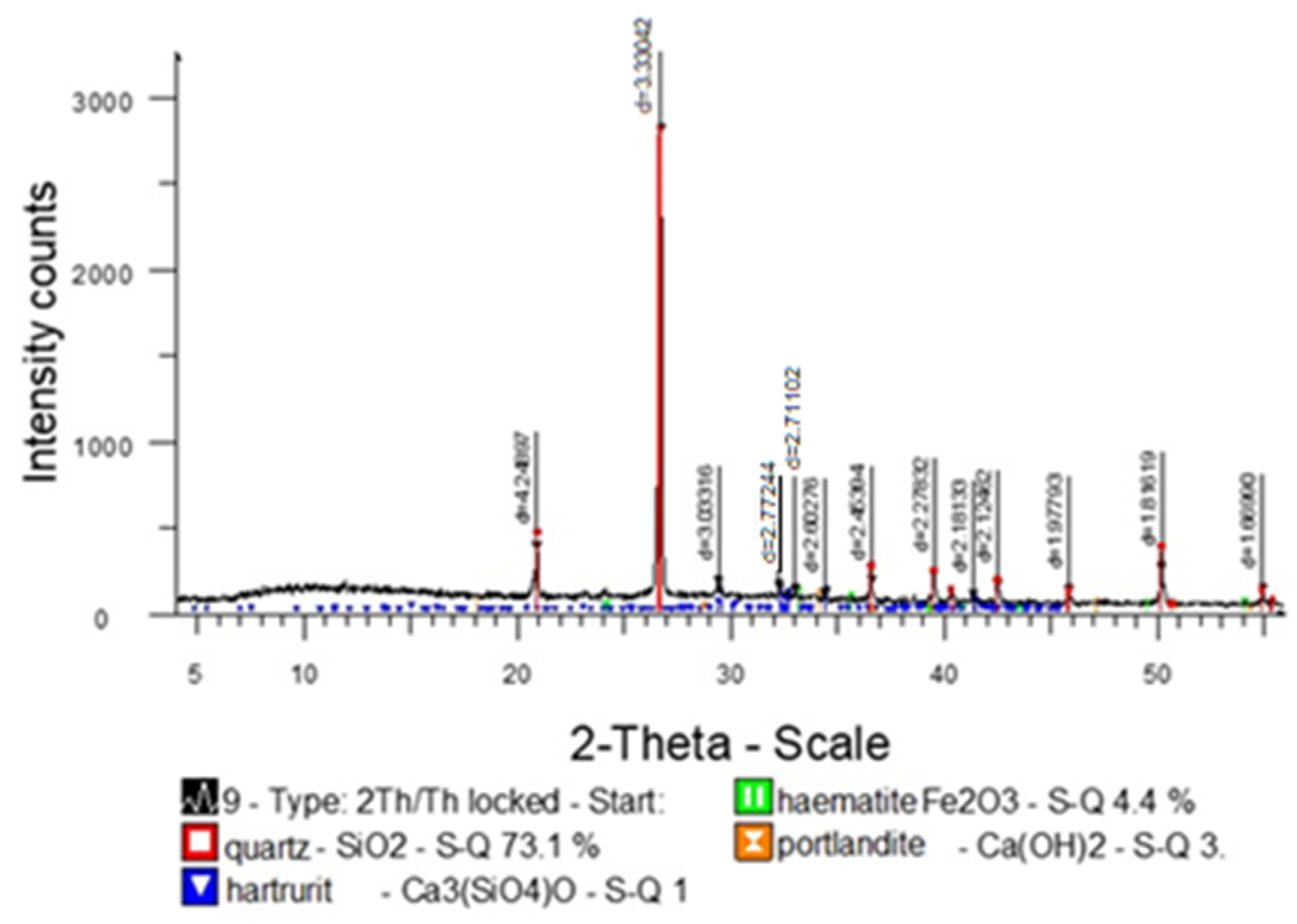
Furthermore, important was the analysis of the effect of the impregnation composition on the concrete structure. As a result, diffractometric X-ray analysis was done for analysis. The diffractometric X-ray analysis was carried out on an automated diffractometer DRON-3 with CuCa-radiation, β-filter. The conditions of diffractogrammetry were as follows: U = 35 kV; I = 20 mA; θ-2θ; detector 2 deg/min. X-ray phase analysis on a semi-quantitative basis was carried out using diffractograms of powder samples using the method of equal weights and artificial mixtures. Quantitative ratios of crystalline phases were determined. Interpretation of diffractograms was carried out using ICDD: Powder Diffraction File PDF2 (Powder Diffraction File) and diffractograms of impurity-free minerals in
Figure 11.
The resulting diffractogram shows that the concrete does not change its structural properties after applying the impregnation compound.
4. Conclusions
The technological peculiarity of the proposed anti-icing coating was the use of keratin, which was obtained in a relatively inexpensive way from the animal-breeding industry waste. The keratin-based ice-coating reduces the adhesive resistance of the ice crust of concrete roads.
Results of laboratory tests on vibration exposure have shown that ice-phobic-coated specimens showed significant disturbance of ice crust continuity (up to 80% of the total area), with its local delamination, whereas uncoated specimens showed only a minor cracking of the ice crust. Ice impact stress tests also showed a positive effect of the ice-break coating. After 25 impacts of ice-coated specimens, the total cracking area was 2.7 times larger than that of uncoated specimens. The average cracking radius was twice as large, confirming the relatively lower adhesion resistance of ice-coated specimens. Thermal stresses of ice-coated specimens showed significant cracking of ice crust with its delamination from the concrete surface by 70% of the total surface area of the specimen. In specimens without ice-break coating, thermal stresses caused local cracking of ice crust, without perceptible disturbance of its continuity. Water absorption tests also showed the effectiveness of the coating, its ability to prevent water penetration and thus reduce the contact area of ice and concrete. The average water absorption value of uncoated samples was 47% higher than that of coated samples.
Overall, the research results have shown the effectiveness of concrete road coating as an ice-phobic material. Reducing the total contact area from solid to dotted reveals a useful property of ice—its brittleness, which has less ability to resist mechanical impact and collapse during contact with the wheel, thus reducing the risk of unstable driving at sub-zero temperatures.


 ,
, 