Article

Numerical Modelling for the Experimental Improvement of Growth Uniformity in a Halide Vapor Phase Epitaxy Reactor for Manufacturing β-Ga2O3 Layers

Department of Physics, Chemistry and Biology (IFM), Linköping University, S-581 83 Linköping, Sweden
*
Author to whom correspondence should be addressed.
Crystals 2022, 12(12), 1790; https://doi.org/10.3390/cryst12121790
Submission received: 23 November 2022 / Revised: 5 December 2022 / Accepted: 7 December 2022 / Published: 9 December 2022
(This article belongs to the Special Issue Wide-Bandgap Semiconductor Materials, Devices and Systems)

Abstract

:
The development of growth processes for the synthesis of high-quality epitaxial layers is one of the requirements for utilizing the ultrawide band gap semiconductor Ga2O3 for high-voltage, high-power electronics. A halide vapor phase epitaxy (HVPE) process used to grow β-Ga2O3 layer was optimized by modifying the gas inlet, resulting in improved growth uniformity. A conventional tube acting as an inlet for the Ga precursor GaCl gas was replaced with a shower head with four outlets at 45 degrees to the horizontal axis of the reactor. The modification was performed based on numerical calculations of the three-dimensional distribution of gases inside the growth chamber with different designs of the GaCl precursor inlet. It was shown that variation in the Ga/O ratio over the substrate holder was ~10% for a shower head compared with ~40% for a tube. In addition, growth with a tube leads to the film thickness varying by a factor of ~4 depending on the position on the holder, whereas when using a shower head, the thickness of the grown Ga2O3 layers became much more uniform with a total spread of just ~30% over the entire substrate holder.

1. Introduction

The development of semiconductor gallium oxide (Ga2O3) is one of the research fields attracting considerable attention due to its promising material properties, such as an ultrawide bandgap with an energy of 4.8 eV and a very high breakdown electric field of ~8 MV/cm for β-polymorphs [1]. Considering that Ga2O3 can outperform GaN and SiC in terms of high-voltage electronics, this semiconductor is important for many potential applications, from efficient solar and wind energy conversion to environmentally friendly electric vehicles [2]. However, to use Ga2O3 for power electronics, it is necessary to improve the growth techniques to produce high-quality single-crystal epitaxial layers suitable for device structures [3].
Growth methods such as molecular beam epitaxy (MBE) and metal–organic vapor phase epitaxy (MOVPE) have commonly been used to synthesize thin films of homoepitaxial and heteroepitaxial Ga2O3 [4,5,6,7,8,9]. Due to the low growth rates of these techniques, typically below 1 μm/h, there is a limitation to produce thick layers which are needed for high-voltage power electronic devices. On the other hand, a high growth rate method such as halide vapor phase epitaxy (HVPE) with growth rates up to hundreds of micrometers per hour has been used to successfully deposit thick layers of Ga2O3 layers [10,11,12,13,14] which can be used to fabricate device structures or as templates for MBE or MOVPE growth.
Previously, we have demonstrated the growth of ~5 µm thick β-Ga2O3 layers on sapphire substrates using the HVPE method [15]. The process was developed using a tube as an inlet. With this geometry, the precursor’s distribution over the substrate holder was not uniform, which affected the thickness of the layers and, in turn, worsened the reproducibility. Thus, in this paper, we report the development of the HVPE process by modifying the gas inlet, which resulted in a significant improvement in the thickness uniformity of the Ga2O3 layers across the substrate holder. The tube was replaced with a so-called shower head with four GaCl outlets placed at 45 degrees relative to the horizontal plane of the reactor. Modification of the gas inlet geometry was based on the results of numerical simulations using a three-dimensional (3D) model of the reactor to optimize the process parameters.

2. Materials and Methods

The growth of Ga2O3 layers was carried out in a horizontal homemade HVPE reactor consisting of a quartz chamber inside a furnace with three different temperature zones, providing the possibility to heat the growth zone up to 1050 °C. The quartz holder for substrates was tilted and placed inside a quartz chamber. Figure 1a shows a schematic illustration of the inlet region and the substrate holder of the reactor. The distance from the GaCl and O2 inlet to the substrate was kept constant at 10 cm. All Ga2O3 layers were grown on 430 mm thick c-axis Al2O3 substrates 1 cm × 1 cm in size at a temperature of 850 °C and at atmospheric pressure. The precursors were GaCl and O2, with flow rates of 10 and 50 sccm, respectively. For comparison, we kept the same flow rates for both the tube and the shower head geometry. Gaseous GaCl was obtained in the reactor by flowing HCl gas through a quartz boat with liquid Ga metal maintained at a temperature of 850 °C. The carrier gas was nitrogen with a total flow rate of 1550 sccm (50 sccm was used as carrier gas flow for the GaCl). The purity of gases was as follows: 99.999% (grade 5.0) for O2 and HCl, and 99.9999% (grade 6.0) for N2. The purity of metallic gallium was 99.99999% (grade 7.0). The growth time was kept to 30 min for all runs. The layer thickness was determined by the weight of the samples before and after growth.
Numerical simulations of the process parameters in a 3D model of the HVPE reactor with different gas inlet geometries were performed using COMSOL Multiphysics software and modules such as the CAD Import Module, the CFD Module, and the Chemical Reaction Engineering Module. The calculations were based on the transport model, which assumed incompressibility of the gas flow. Due to the mirror symmetry with respect to the vertical plane of the HVPE reactor, the calculation time could be reduced using a model representing half of the reactor. Details on the model and the used mesh have been presented elsewhere [15].
Optical reflection images were measured using a light microscope. For X-ray diffraction (XRD) measurements, a PANalytical X’Pert Pro instrument with Cu–Kα radiation was applied. Scanning electron microscopy (SEM) images and cathodoluminescence (CL) spectra taken at room temperature were measured with an electron beam acceleration voltage of 10 kV using a Leo 1500 Gemini SEM and a MonoCL4 in situ SEM instrument.

3. Results

The growth of epitaxial layers with reasonable uniformity and quality over a large area in horizontal HVPE reactors requires, as a rule, the uniform mixing of process gases over the substrate. Due to the low binary diffusion coefficient between the GaCl precursor and the N2 carrier gas, this can be challenging when using a simple tube as the gas inlet for GaCl. Thus, we modified the inlet geometry for GaCl gas. Hence, instead of using a tube, we decided to use a shower head. Before modifying the parts of the reactor, we performed calculations of the gas distribution in the reactor with different inlet geometries. The simulated region of the reactor is shown schematically in Figure 1a. The shower head consisted of a T-shaped tube with four outlets for GaCl, as illustrated in Figure 1b. The rotation angle of the shower head was defined as the angle between the horizontal axis of the reactor and the direction of the four outlet holes of the shower head. All calculations were performed for a growth temperature of 850 °C and for gas flow rates of 10, 50, and 1550 sccm for GaCl, O2, and N2, respectively, which correspond to the optimized growth parameters for using a tube as the GaCl inlet [15]. We calculated the distribution of gases in the reactor using the rotation angles for GaCl outlets equal to 0, 20, 45, and 60 degrees. Figure 1c illustrates an example of a 3D gas velocity distribution for a shower head with outlets at a rotation angle of 60 degrees.
To demonstrate how gaseous precursors are distributed over the sample holder depending on the different geometry of the inlet, mole fractions of O2 and GaCl gases were calculated along the x-axis at the coordinate y = 1 cm (L = 1 cm in Figure 2a), as shown in Figure 2b,c. Comparisons were performed for a tube and for a shower head at different rotation angles of the outlet holes of 0, 20, 45, and 60 degrees. In the case of oxygen, the concentration variations along the x-axis were small, about ~10% for all cases, whereas for GaCl, significant improvements in uniformity were observed when using a shower head. The difference in GaCl concentration along the x-axis was ~40% for a tube, whereas in the case of a shower head, the variation in GaCl concentration in the x-direction decreased from ~12% for a rotation angle of 0 degrees to almost negligible at 60 degrees.
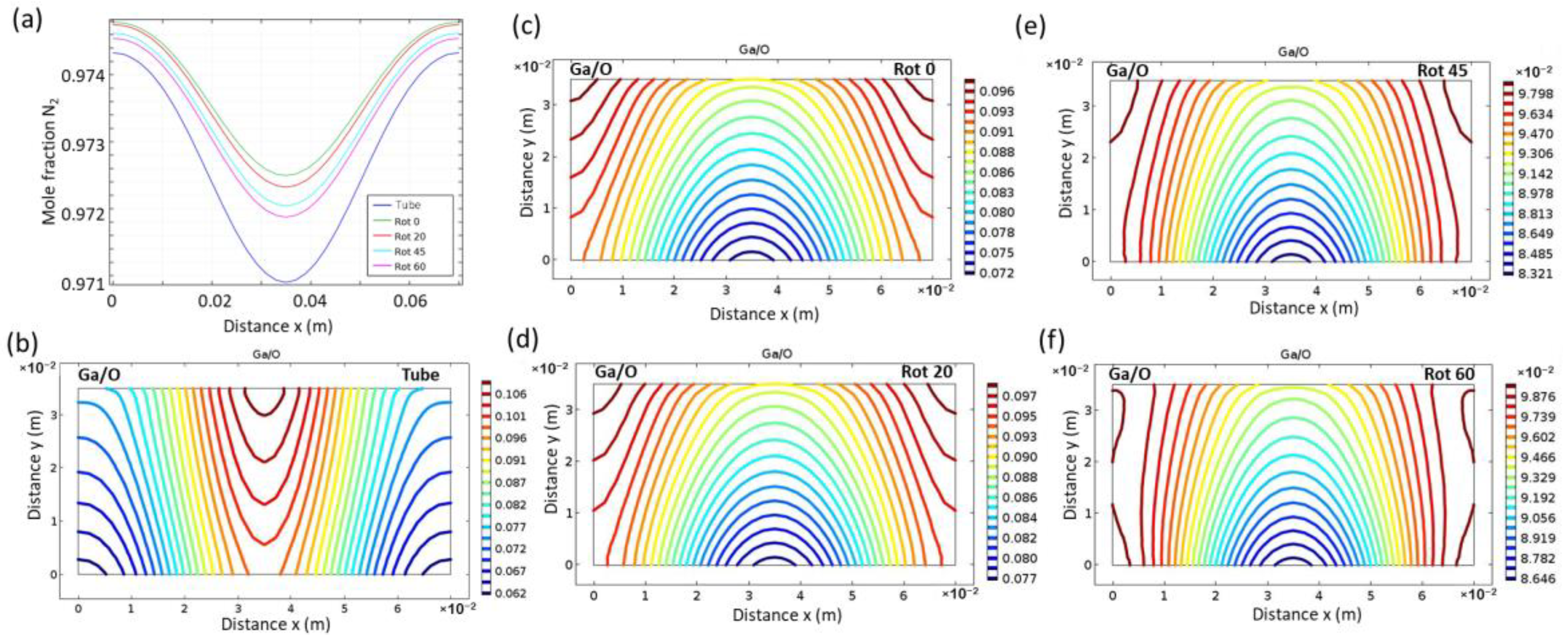
The distribution uniformity of the carrier gas N2 was not affected by the inlet geometry, as shown in Figure 3a, where the nitrogen concentration varies by less than 0.5% along the x-axis for all cases, and the use of a tube or shower head affects the nitrogen concentration by less than 0.2%.
The distribution of both Ga and O is important for growth uniformity; therefore, we plotted a 2D distribution of the Ga/O ratio over the sample holder using a tube as the gas inlet (Figure 3b) and for a shower head with different outlet rotation angles (see Figure 3c–f).
The comparison of Figure 3b with Figure 3c–f clearly demonstrates that the use of a shower head significantly improves the uniformity of the precursor distribution over the growth zone. The best results in terms of uniformity were achieved at larger rotations angles. Thus, the information obtained as a result of numerical simulations is very valuable for the experimental modifications of reactor gas inlets. The shower head was manufactured of quartz with a rotation angle of 45 degrees, which was made to fit the current geometry of the reactor.
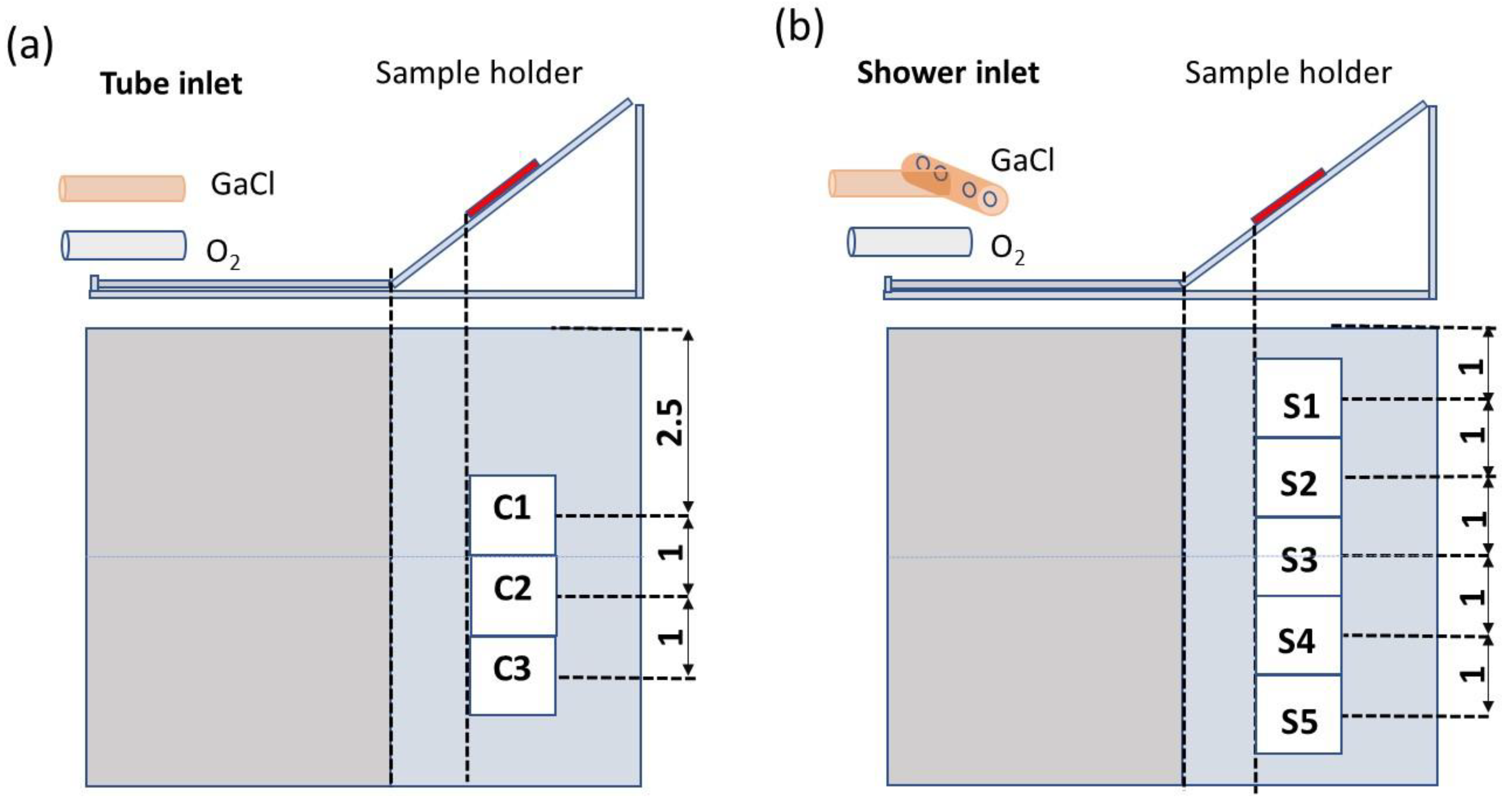
The effect of the inlet design on the uniformity, morphology, crystalline quality, and optical properties of Ga2O3 layers have been studied. In these growth experiments using different gas inlets, all other process parameters were kept constant, i.e., the growth temperature was 850 °C and the GaCl and O2 flows were 10 and 50 sccm, respectively. Figure 4 shows how the substrates were placed on the sample holder in the case using a tube or shower head as the gas inlet, respectively, as well as the labelling of the samples.
The geometry of the gas inlet had a crucial effect on the thickness uniformity. Using a tube as the inlet, the thickness differed by more than fourfold (see Table 1). For sample C3, located closer to the holder edge, there was almost no growth. The use of a shower head for the GaCl precursor significantly improved the growth uniformity. In this case, the difference in thickness of the Ga2O3 layers grown in the center (S3) and at the edges of the sample holder (S1, S5) was only about 30% (Table 1).
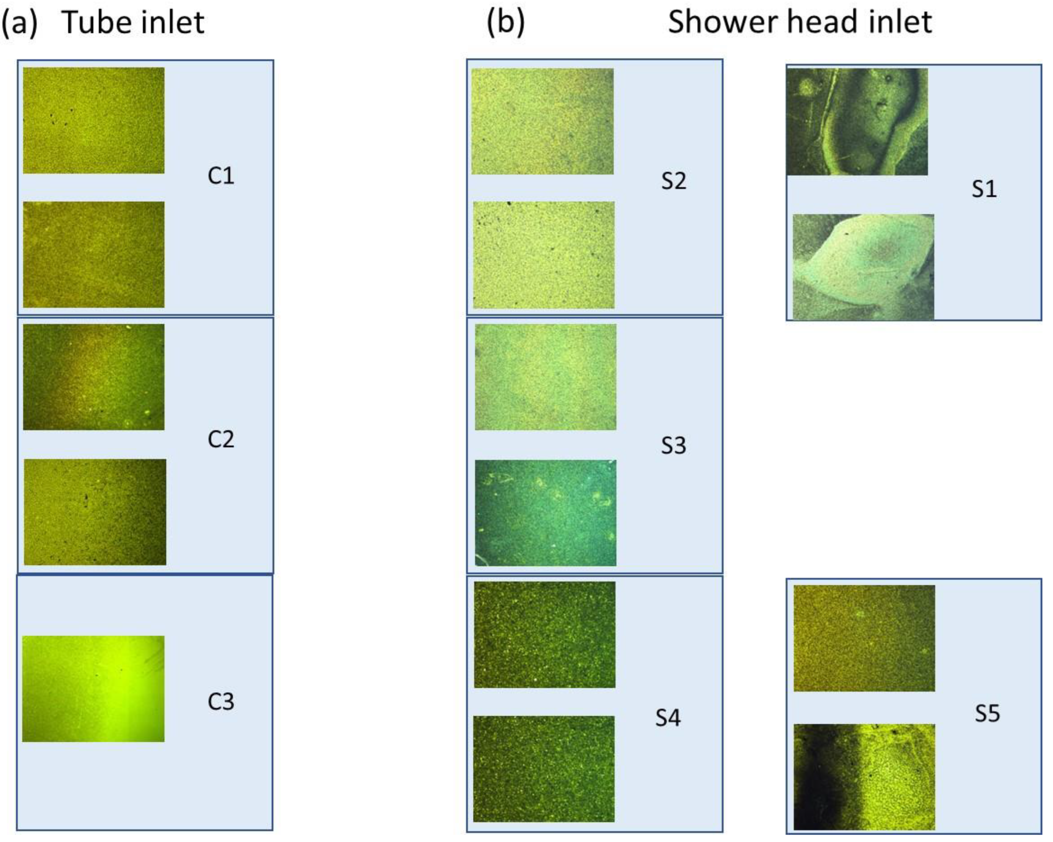
The surface characteristics of the Ga2O3 layers can be evaluated from the optical reflection images shown in Figure 5a,b for samples grown using a tube or a shower head, respectively. Images are taken in the areas of the sample schematically indicated in Figure 5. The growth rate was negligible for sample C3; therefore, the optical image shows the substrate surface. When grown with a shower head, the surface morphology was uniform for the samples placed around the middle of the holder (S2–S4), whereas the images of the samples grown at the edges of the holder (S1, S5) reveal irregularities in the surface. This is likely due to non-laminar gas flow near the left and right side edges of the substrate holder, because there was a gap of a few millimeters between the holder and the reactor wall. This is not covered by the simplified simulated geometry. Additionally, parasitic growth can affect the III/VI precursor ratio near the reactor walls.
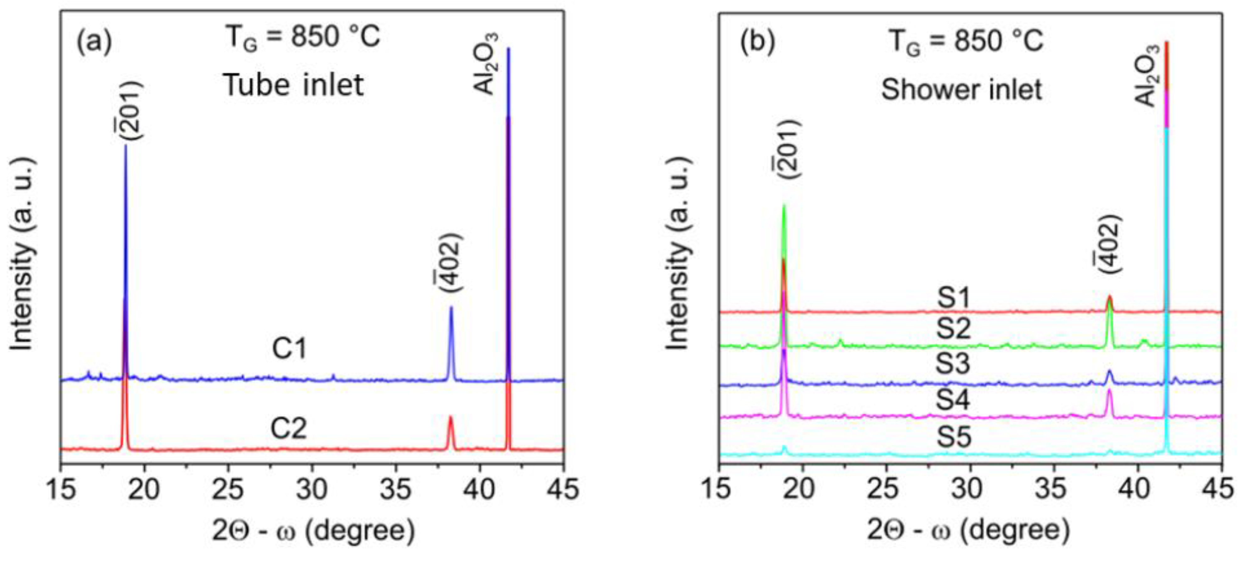
The structural quality of the β-Ga2O3 layers grown with different inlets was examined by XRD measurements. As shown in Figure 6a, β-Ga2O3 layers C1 and C2 exhibit good alignment and single-crystal quality with reflection peaks from the (−201) and (−402) planes in addition to the (0006) XRD peak from sapphire, which is similar to previous reports for heteroepitaxial β-Ga2O3 on Al2O3 (0001) substrates [10,11,16]. The slightly higher intensity of the XRD peaks for sample C1 compared with C2 is due to the difference in layer thickness. For samples grown with a shower head, the XRD spectra also showed reflection peaks from the (−201) and (−402) planes (see Figure 6b); however, the structural quality of the layers was slightly worse, judging from the signal-to-noise ratio even compared with the XRD spectrum for a thinner sample, C2, in Figure 6a. The deterioration of the structural quality was especially evident for the samples located at the edges of the holder (S1, S5), for which the surface morphology was inhomogeneous. The decrease in the structural quality for samples grown with a shower head is associated with a lower Ga/O ratio in the growth zone compared with the case of using a tube as the GaCl inlet, according to our calculations (see Figure 3b,e). This is consistent with previous observations when the crystal quality of HVPE-grown Ga2O3 layers deteriorated due to the lower Ga/O precursor ratio [15].
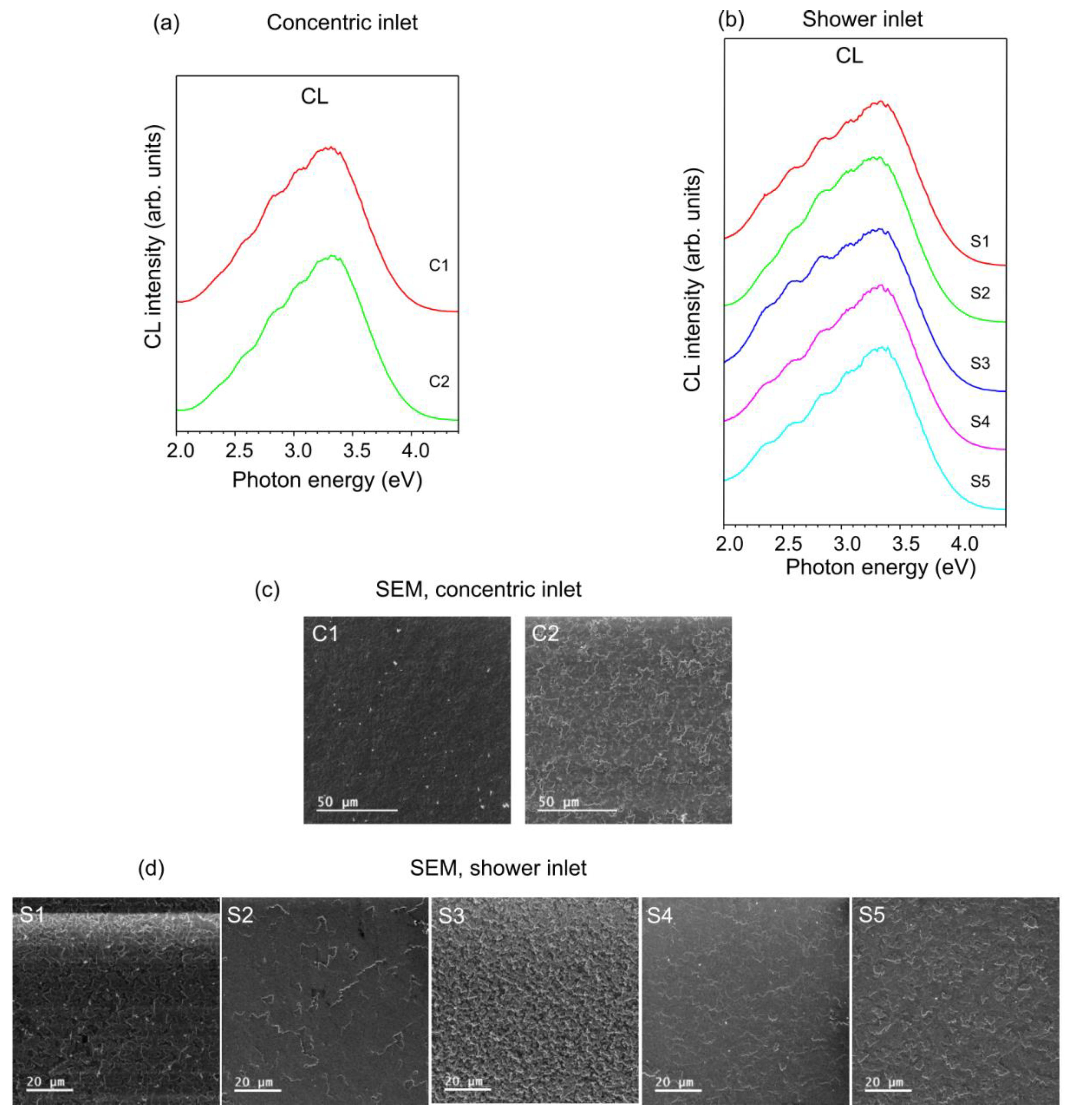
The CL spectra and corresponding SEM images of the sample surface where the measurements were taken are shown in Figure 7 for the cases using a tube (Figure 7a) and a shower head (Figure 7b) as the inlet. Comparisons of the CL spectra show small variations between all Ga2O3 layers regardless of the inlet design. CL is dominated by a broad UV emission at ~3.30 eV with several overlapping recombination bands at lower energies of ~3.04, 2.80, 2.58, and 2.35 eV. The UV luminescence in β-Ga2O3 was previously attributed to the recombination of electrons and self-trapped holes [17,18,19,20]. Other features in the CL spectra named after the corresponding color of the spectral region are associated with defect-related transitions. Thus, the blue bands at 2.8–3.0 eV correspond to the recombination between deep donors and acceptors, such as O and Ga vacancies, respectively [21]. Green emission at ~2.4–2.5 eV is still under discussion. This can be attributed to the recombination of excitons bound to intrinsic defects in accordance with theoretical calculations for a recombination energy of 2.3 eV obtained for a weakly bound electron with a hole trapped on the interstitial oxygen, O i 0 [22]. The SEM images for all samples show comparable morphology, which are correlated with the XRD spectra in Figure 6b. Notably, the use of the shower head resulted in a significant improvement in thickness uniformity while maintaining good optical and structural quality of the layers. This modification of the gas inlet is critical for scaling up the HVPE process and further developing high-quality large-area Ga2O3 layers for electronic applications.

4. Conclusions

We have demonstrated a significantly improved uniformity of β-Ga2O3 growth by HVPE method in a reactor with a modified gas inlet design. The modification was carried out based on theoretical modelling of the reactor and a comparison of using a common tube as the GaCl inlet with a shower head having four output holes located at an angle relative to the input hole and to the horizontal axis of the reactor. Different rotation angles between 0 and 60 degrees were considered and, according to numerical simulations, the variation in the GaCl precursor concentration in the growth zone was significantly reduced from ~40% to approximately 10% through the use of a shower head instead of a tube as the GaCl inlet. The growth of samples was compared with a tube and with a shower head manufactured with a rotation angle of 45 degrees. We have demonstrated that when using a shower head as the GaCl inlet, the thickness of the grown layers became uniform over the entire sample holder, enabling expansion of the growth zone and use of the HVPE reactor to synthesize samples with a larger area.

Author Contributions

Conceptualization, G.P.; methodology, C.-W.H. and N.A.; software, C.H.; validation, G.P., C.-W.H. and C.H.; investigation, G.P., C.-W.H., N.A. and C.H.; data curation, C.H.; writing—original draft preparation, G.P.; writing—review and editing, C.H.; visualization, G.P. and C.H., project administration, G.P. and C.H.; funding acquisition, G.P. and C.H. All authors have read and agreed to the published version of the manuscript.

Funding

This research was funded by the Swedish Research Council (2018-04552, 2019-05154) and the Swedish Energy Agency (46563-1).

Institutional Review Board Statement

Not applicable.

Informed Consent Statement

Not applicable.

Data Availability Statement

The data presented in this study are available on reasonable request from the corresponding author.

Conflicts of Interest

The authors declare no conflict of interest.

References

  1. Pearton, S.J.; Yang, J.; Cary, P.H., IV; Ren, F.; Kim, J.; Tadjer, M.J.; Mastro, M.A. A review of Ga2O3 materials, processing, and devices. Appl. Phys. Rev. 2018, 5, 011301. [Google Scholar] [CrossRef] [Green Version]
  2. Tsao, J.Y.; Chowdhury, S.; Hollis, M.A.; Jena, D.; Johnson, N.M.; Jones, K.A.; Kaplar, R.J.; Rajan, S.; van de Walle, C.G.; Bellotti, E.; et al. Ultrawide-bandgap semiconductors: Research opportunities and challenges. Adv. Electron. Mater. 2018, 4, 1600501. [Google Scholar] [CrossRef] [Green Version]
  3. Higashiwaki, M. Chapter One-Fundamental technologies for gallium oxide transistors. Semicond. Semimet. 2021, 107, 1–22. [Google Scholar]
  4. Sasaki, K.; Kuramata, A.; Masui, T.; Villora, E.G.; Shimamura, K.; Yamakoshi, S. Device-quality β-Ga2O3 epitaxial films fabricated by ozone molecular beam epitaxy. Appl. Phys. Express 2012, 5, 035502. [Google Scholar] [CrossRef]
  5. Oshima, T.; Okuno, T.; Fujita, S. Ga2O3 thin film growth on c-plane sapphire substrates by molecular beam epitaxy for deep-ultraviolet photodetectors. Jpn. J. Appl. Phys. 2007, 46, 7217–7220. [Google Scholar] [CrossRef]
  6. Sasaki, K.; Higashiwaki, M.; Kuramata, A.; Masui, T.; Yamakoshi, S. Growth temperature dependences of structural and electrical properties of Ga2O3 epitaxial films grown on β-Ga2O3 (010) substrates by molecular beam epitaxy. J. Cryst. Growth 2014, 392, 30–33. [Google Scholar] [CrossRef]
  7. Park, J.H.; McClintock, R.; Jaud, A.; Dehzangi, A.; Razeghi, M. MOCVD grown β-Ga2O3 metal-oxide-semiconductor field effect transistors on sapphire. Appl. Phys. Exp. 2019, 12, 095503. [Google Scholar] [CrossRef]
  8. Du, X.; Mi, W.; Luan, C.; Li, Z.; Xia, C.; Ma, J. Characterization of homoepitaxial β-Ga2O3 films prepared by metal–organic chemical vapor deposition. J. Cryst. Growth 2014, 404, 75–79. [Google Scholar] [CrossRef]
  9. Baldini, M.; Albrecht, M.; Fiedler, A.; Irmscher, K.; Klimm, D.; Schewski, R.; Wagner, G. Semiconducting Sn-doped β-Ga2O3 homoepitaxial layers grown by metal organic vapour-phase epitaxy. J. Mater. Sci. 2016, 51, 3650–3656. [Google Scholar] [CrossRef]
  10. Oshima, Y.; Villora, E.G.; Shimamura, K. Quasi-heteroepitaxial growth of β-Ga2O3 on off-angled sapphire (0001) substrates by halide vapor phase epitaxy. J. Cryst. Growth 2015, 410, 53–58. [Google Scholar] [CrossRef]
  11. Xiong, Z.N.; Xiu, X.Q.; Li, Y.W.; Hua, X.M.; Xie, Z.L.; Chen, P.; Liu, B.; Han, P.; Zhang, R.; Zheng, Y.D. Growth of β-Ga2O3 films on sapphire by hydride vapor phase epitaxy. Chin. Phys. Lett. 2018, 35, 058101. [Google Scholar] [CrossRef]
  12. Murakami, H.; Nomura, K.; Goto, K.; Sasaki, K.; Kawara, K.; Thieu, Q.T.; Togashi, R.; Kumagai, Y.; Higashiwaki, M.; Kuramata, A.; et al. Homoepitaxial growth of β-Ga2O3 layers by halide vapor phase epitaxy. Appl. Phys. Exp. 2015, 8, 015503. [Google Scholar] [CrossRef]
  13. Konishi, K.; Goto, K.; Togashi, R.; Murakami, H.; Higashiwaki, M.; Kuramata, A.; Yamakoshi, S.; Monemar, B.; Kumagai, Y. Comparison of O2 and H2O as oxygen source for homoepitaxial growth of β-Ga2O3 layers by halide vapor phase epitaxy. J. Cryst. Growth 2018, 492, 39–44. [Google Scholar] [CrossRef]
  14. Nikolaev, V.I.; Pechnikov, A.I.; Stepanov, S.I.; Nikitina, I.P.; Smirnov, A.N.; Chikiryaka, A.V.; Sharofidinov, S.S.; Bougrov, V.E.; Romanov, A.E. Epitaxial growth of (−201) β-Ga2O3 on (0001) sapphire substrates by halide vapour phase epitaxy. Mater. Sci. Semicon. Process. 2016, 47, 16–19. [Google Scholar] [CrossRef]
  15. Pozina, G.; Hsu, C.W.; Abrikossova, N.; Kaliteevski, M.A.; Hemmingsson, C. Development of β-Ga2O3 layers growth on sapphire substrates employing modeling of precursors ratio in halide vapor phase epitaxy reactor. Sci. Rep. 2020, 10, 22261. [Google Scholar] [CrossRef]
  16. Nakagomi, S.; Kokubun, Y. Crystal orientation of β-Ga2O3 thin films formed on c-plane and a-plane sapphire substrate. J. Cryst. Growth 2012, 349, 12–18. [Google Scholar] [CrossRef]
  17. Harwig, T.; Kellendonk, F.; Slappendel, S. The ultraviolet luminescence of β-galliumsesquioxide. J. Phys. Chem. Solids 1978, 39, 675–680. [Google Scholar] [CrossRef]
  18. Harwig, T.; Kellendonk, F. Some observations on the photoluminescence of doped β-galliumsesquioxide. J. Solid State Chem. 1978, 24, 255–263. [Google Scholar] [CrossRef]
  19. Villora, E.G.; Atou, T.; Sekiguchi, T.; Sugawara, T.; Kikuchi, M.; Fukuda, T. Cathodoluminescence of undoped β-Ga2O3 single crystals. Solid State Commun. 2001, 120, 455–458. [Google Scholar] [CrossRef]
  20. Onuma, T.; Fujioka, S.; Yamaguchi, T.; Higashiwaki, M.; Sasaki, K.; Masui, T.; Honda, T. Correlation between blue luminescence intensity and resistivity in β-Ga2O3 single crystals. Appl. Phys. Lett. 2013, 103, 041910. [Google Scholar] [CrossRef] [Green Version]
  21. Binet, L.; Gourier, D. Origin of the blue luminescence of β-Ga2O3. J. Phys. Chem. Solids 1998, 59, 1241–1249. [Google Scholar] [CrossRef]
  22. Ho, Q.D.; Frauenheim, T.; Deak, P. Origin of photoluminescence in β-Ga2O3. Phys. Rev. B 2018, 97, 115163. [Google Scholar] [CrossRef]
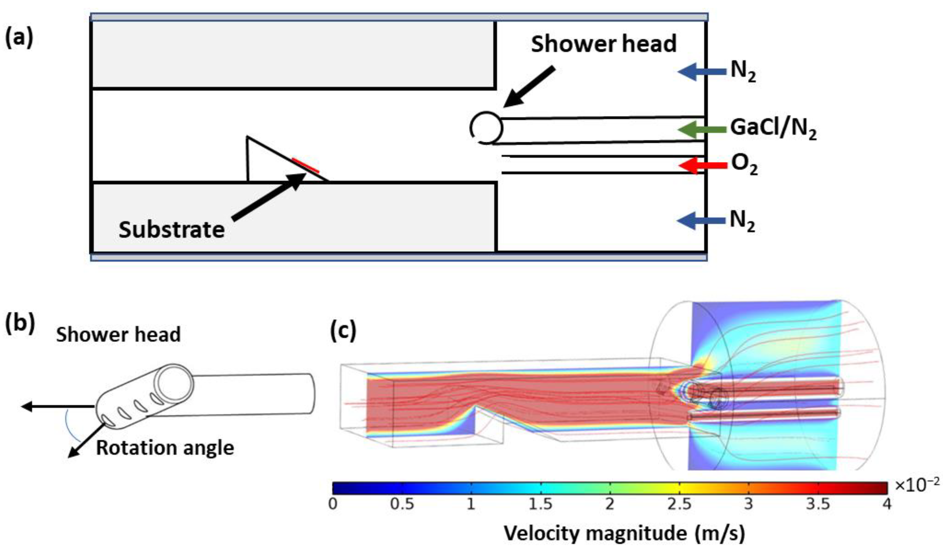
Figure 1. (a) Schematic drawing of the simulated part of the reactor with a shower head inlet for GaCl. (b) The shower head with possible rotation angles of its outlets relative to the horizontal axis. (c) The reactor flow geometry with an example of a 3D simulation of the gas velocity and streamlines for the velocity field inside the reactor using a shower head with a rotation angle of 60 degrees.
Crystals 12 01790 g001
Figure 2. (a) Sample holder with a coordinate system and the 2D distribution of (b) mole fraction of oxygen and (c) mole fraction of GaCl over the sample holder in the x-direction when L = 1 cm from the front edge of the sample holder. The calculations were carried out for different rotation angles of the outlets and compared with the model with a tube as the inlet for GaCl.
Crystals 12 01790 g002
Figure 3. (a) Plots of the N2 molar fraction calculated on the surface of the sample holder along the x-axis for the coordinate y = 1 cm. (b) The 2D distribution of the Ga/O ratio on the surface of the sample holder, calculated for the model using a tube as the gas inlet, and the 2D distribution of the Ga/O ratio on the sample holder calculated for a shower head with a rotation angle for outlets of 0 degrees (c), 20 degrees (d), 45 degrees (e), and 60 degrees (f). All calculations were performed for T = 850 °C and for GaCl and O2 gas flows of 10 and 50 sccm, respectively.
Crystals 12 01790 g003
Figure 4. (a) The top drawing shows a schematic of the gas inlet for the GaCl and O2 precursor and side-view of the substrate holder. The bottom drawing shows the positions of the samples with distances from the edge of the sample holder indicated in centimeters for each specimen. The samples are labelled C1–C3. (b) Similar schematic drawings as in (a), but for the shower head. Samples are labelled S1–S5.
Crystals 12 01790 g004
Figure 5. Optical reflection images for samples grown using a tube (a) and a shower head (b) as the inlet. The images were taken with a magnification of 50×.
Crystals 12 01790 g005
Figure 6. XRD spectra of β-Ga2O3 layers grown on sapphire (0001) using a tube (a) and a shower head (b) as the gas inlet. The spectra are shifted vertically for clarity.
Crystals 12 01790 g006
Figure 7. CL spectra measured at room temperature for β-Ga2O3 layers grown using a tube (a) and a shower head (b) as the GaCl inlet. The spectra are normalized and shifted along the vertical axis for clarity. The SEM images show the areas where the CL spectra were acquired for each sample in the case of a (c) concentric and (d) shower inlet.
Crystals 12 01790 g007
Table 1. Thickness of samples grown with two geometries: tube and shower head.
GeometrySampleThickness of Grown Layer, µm
TubeC14.26
C20.91
C3~no growth
Shower headS11.06
S21.62
S31.56
S41.47
S51.05
Publisher’s Note: MDPI stays neutral with regard to jurisdictional claims in published maps and institutional affiliations.