Article

Study on the Surface Morphology of Micro-Particles and the Oxide Layer on Silicon Carbide Crystal Using Nanosecond Green Laser Cleaning Assisted with Airflow

1
Intelligent Manufacturing and Equipment School, Shenzhen Institute of Information Technology, Shenzhen 518172, China
2
Key Laboratory of Advanced Optical Precision Manufacturing Technology of Guangdong Higher Education Institutes, Shenzhen Technology University, Shenzhen 518060, China
3
Shenzhen Hymson Laser Technology Co., Ltd., Shenzhen 518110, China
*
Author to whom correspondence should be addressed.
Crystals 2022, 12(12), 1788; https://doi.org/10.3390/cryst12121788
Submission received: 26 October 2022 / Revised: 1 December 2022 / Accepted: 3 December 2022 / Published: 8 December 2022
(This article belongs to the Special Issue Advanced Laser Technology and Applications)

Abstract

:
With a focus on the particle pollutants on the surface of silicon carbide crystal materials, this paper establishes a laser cleaning model for the fine particles found in silicon carbide crystal materials and proposes a new nanosecond green laser cleaning method assisted by airflow, which can effectively remove microparticles and the oxide layer on the substrate surface. Abaqus software and ANSYS Fluent software were used to simulate changes in the cleaning temperature field and the distribution of particles and dust during cleaning simulation, respectively. Based on the experimental research, and by using a nanosecond green laser to produce a wavelength of 532 nm, the direct irradiation of a nanosecond green laser on the surface of the element, and the particle contaminants on the surface of the silicon carbide material, optimized the process parameters to achieve a better cleaning efficiency. A green laser was used as a light source to conduct experiments to control the wind force of the gas chamber. The influence of the laser energy, scanning speed, and other parameters on the final cleaning efficiency was studied. The parameters of the silicon carbide before and after cleaning were characterized. The research shows that laser cleaning assisted with airflow is an efficient cleaning method that can be used to clean microparticles without damaging silicon carbide crystal substrate and to reduce the surface roughness of silicon carbide material from 1.63 to 0.34 μm, with an airflow of 0.2 Mpa.

1. Introduction

Silicon carbide is a typical ceramic crystal material. Due to its stable chemical properties, high thermal conductivity, small thermal expansion, and abrasiveness, silicon carbide has many uses. For example, silicon carbide can be used to make nanometer materials used in cylinders due to its high thermal conductivity, thermal stability, oxidation resistance, chemical corrosion resistance, low thermal expansion coefficient, good chemical stability, high mechanical properties, etc. and it also has a high band gap width. The higher the abrasiveness and the larger the particle size in silicon carbide particle sand, the better its hardness and grinding performance. A silicon carbide crystal block usually contains about 98% SiC, with the rest of the composition being impurities (mainly Si dioxide) [1,2,3]. Yp A. et al. [4], from the Harbin Institute of Technology, proposed a new method: an improved laser scanning contour ablation method with a continuous variable to account for the removal depth of the silicon carbide material. Laser cleaning methods have been proposed and tested via the YAG laser cleaning of surface contaminants [5]. Klein S. et al. [6] studied marble discoloration during dry laser cleaning using Nd:YAG laser wavelengths from different substrates (Si, Ge, and NiP). Zheng Y. W. and Fieret J. et al. [7,8] investigated the dry laser cleaning of particles from solid substrates, and their studies show that the efficiency of silicon substrates was measured for different laser fluences ranging from 50 to 250 mJ/cm2. Allcock D. et al. [9] determined that laser cleaning dry surfaces used pulsed laser irradiation, which resulted in enhanced removal efficiency. Nanosecond Nd: YAG laser cleaning has many advantages that have been proven compared with mechanical and chemical cleaning [10]. Some scholars [11,12,13] developed a theory and method of laser cleaning and obtained valuable research results. Zapka W. et al. [14] conducted the laser-induced removal of particles from surfaces with different laser wavelengths. Harris C. D. et al. and Kim J. E. [15,16] studied and verified the removal mechanism of laser cleaning via laser cleaning experiments conducted on metallic surface oxide. Lu Y. F. et al. [17,18] characterized the ejected particles during laser cleaning using the recently developed “steam laser cleaning” method. The particle ejecting energies were found to increase with the laser fluence [19]. A previous study [20,21] summarized the laser cleaning of other materials from 6061 aluminum alloy, metal oxide to bronze. Guo L. et al. [22] systematically conducted a numerical and experimental analysis for morphology evolution of 6061 aluminum alloy during nanosecond pulsed laser cleaning. Some scholars studied the laser cleaning process and parameter optimization, such as laser angular [23], laser beam [24], and laser power [25]. Kennedy C.J. [26] proposed the laser cleaning of parchment method and studied the effect of laser on collagenous structure of parchment via changing wavelength and energy density. Lee J M. et al. [27] studied the removal of the small particles on silicon wafers via laser-induced airborne plasma shock waves. In addition to these methods, the optimized pulse duration approach was applied to remove surface layer pollutant via laser cleaning [28]. Kim J. E. [29] and Chen T. et al. [30] studied multi-scale micro-nano structures prepared using laser-cleaning- assisted laser ablation of silicon surfaces in ambient air. Zhang S. et al. [31] introduced the LSC method, which is a type of laser shock wave cleaning, with its advantages in decontaminating various micron- and nano-scale contaminated particles in silicon. Liu Y. et al. [32] studied the cleaning mechanism of a ship shell plant surface involved in dry laser cleaning using controlling laser power via experimental investigations. Zhu GD [33] investigated the mechanism and application of laser cleaning. In recent years, there has also been some literature on particle removal and characterization of self-cleaning properties via laser cleaning [34,35,36].
Previously, methods to clean the microparticles of silicon carbide ceramic materials efficiently without damaging the substrate constituted a key area of research. Laser cleaning is an important field in laser precision manufacturing, and it is a new, efficient green manufacturing technology. This paper presents a method that combines a laser and inert gas: the inert gas is blown on to the substrate surface during laser radiation. After the dirt has been removed from the surface, it is blown off the surface with the help of gas to achieve efficient laser cleaning.

2. Machining Principle of Laser Cleaning Assisted with Gas and Numerical Simulation

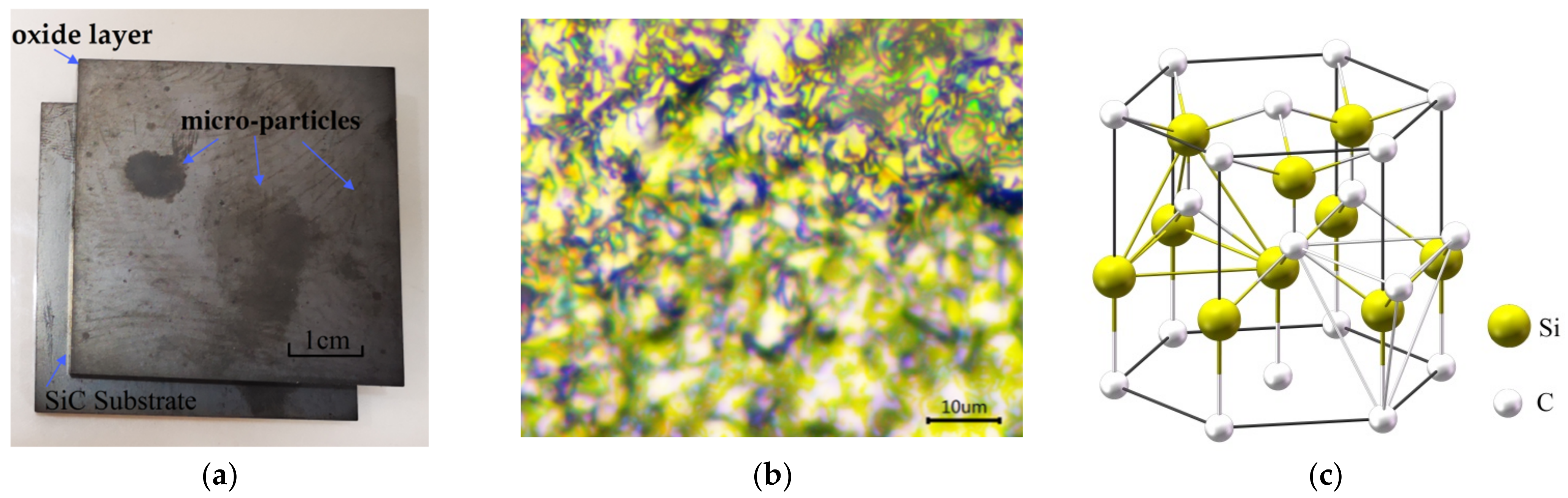
2.1. Silicon Carbide (SiC) Single-Crystal Material

Silicon carbide crystal materials are a type of inorganic material, the chemical formula of which is also found in nature as a rare mineral. Silicon carbide can be divided into black silicon carbide and green silicon carbide. Both have a hexagonal crystal shape, specific gravity of 3.20~3.25, and a microhardness of 2840~3320 kg/mm2. Some studies indicate that silicon carbide materials are atomic crystals, therefore, regarding the melting boiling point of the high and low bond length, the shorter the bond length, the greater the bond energy and higher the melting boiling point. Crystal silicon has a Si-Si bond, and silicon carbide has a C-Si bond, because the atomic radius of C is less than Si. Therefore, the C-C bond length is the shortest, the Si-Si bond length is the longest, and the length of the C-Si bond is in between these two values. As for the melting and boiling points, diamond > silicon carbide > crystalline silicon [2,23]. The surface layer of silicon carbide material and the matrix belong to the homogeneous layer, and the membrane layer material, or the metabolites of the basal layer, contains various corrosion or decay products. The physical and chemical parameters of SiC and the oxide layer on the surface are shown in Table 1. The crystal material structure is shown in Figure 1. Figure 1a shows photos of the SiC crystal, Figure 1b shows SiC crystal micrographs using a microscope, and Figure 1c shows SiC covalent bonding. There are four carbon atoms and four Si atoms in a crystal cell. The lattice structure is composed of two sublattices with a dense arrangement.

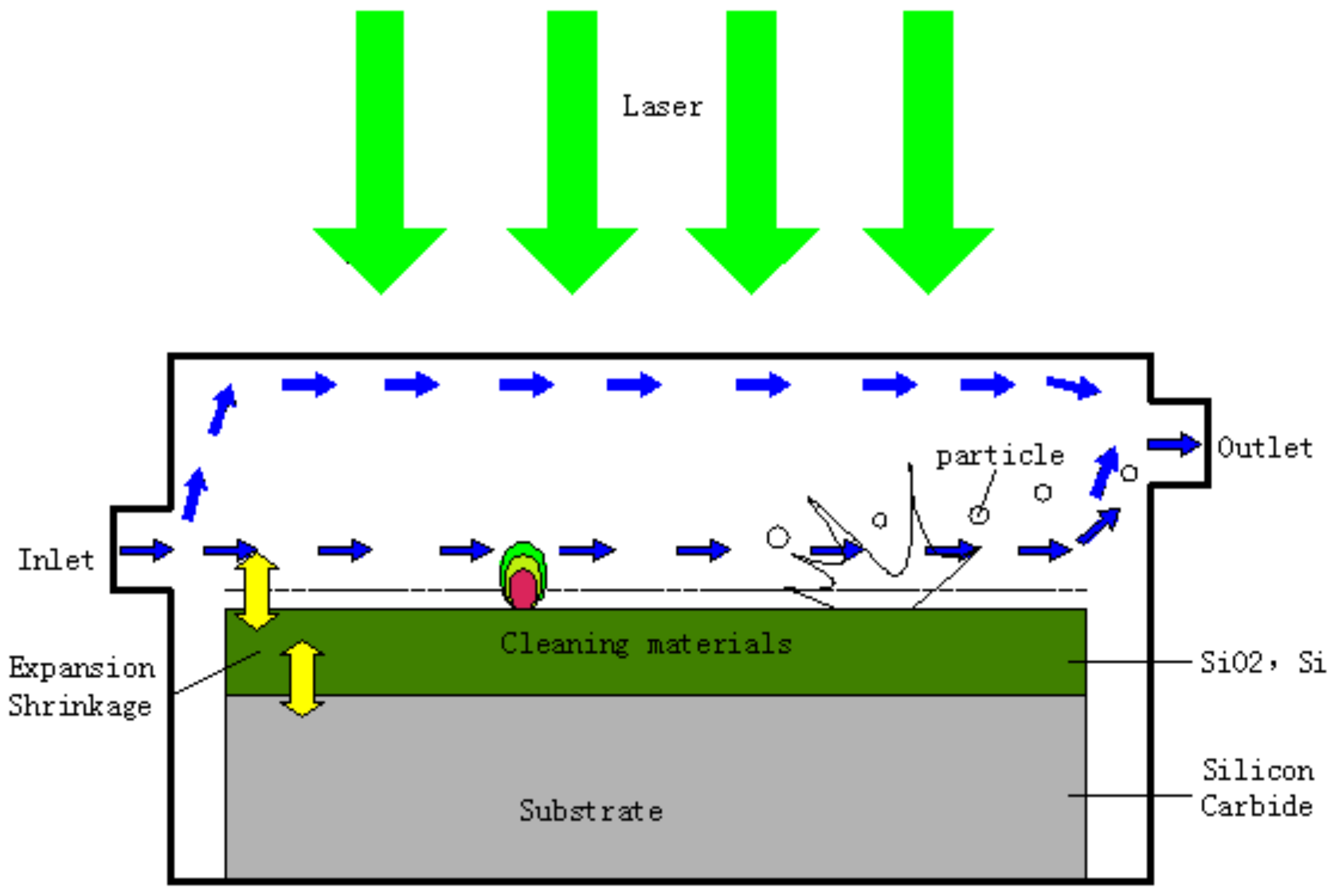
2.2. Principles of Laser Cleaning Assisted by Airflow

As updated from previous studies [37,38,39], the main cleaning mechanism is a gasification mechanism. The cleaning effect is realized when the laser energy density reaches the ablation threshold of the surface layer, and efficient cleaning is achieved with the assistance of gas. Dust cleaning via laser action on the surface of silicon carbide material can be suspended in the air of surrounding solid particles. Laser cleaning has no grinding, no contact, and no thermal effects and has characteristics that make it suitable for cleaning various materials. It is considered to be the most reliable and effective solution. A schematic diagram of laser cleaning assisted by airflow is shown in Figure 2. The principle of laser cleaning assisted by airflow is that the beam emitted by the laser is absorbed. The absorption of large amounts of energy forms rapidly expanding plasma, creating a shock wave that splinters or evaporates pollutants. Plasma is only produced if the energy density is above a threshold, which depends on the contaminant or oxide layer being removed. The auxiliary gas exits the particles to accelerate the cleaning process, and the cleaning threshold effect is very important for effective cleaning while ensuring the safety of the substrate material. Laser cleaning assisted by flow is to remove pollutants via direct laser irradiation on the physical and pollutant surface through the interaction between laser and material. A different mechanism of laser action is used to generate an external force, overcoming the adsorption force of pollutants and the base surface and finally removing the pollutants from the surface of the object with the assistance of gas to achieve surface cleaning.
Laser cleaning based on an ablative effect refers to the laser irradiation of pollutants on the surface of the matrix. The pollutants absorb laser energy, the temperature rises to above the melting or boiling point, and physical and chemical changes occur, such as decomposition, combustion, or gasification, removing pollutants from the surface of the matrix. The thermal effect generated by the laser also creates an ablation effect. Since the size of the laser spot is larger than the heat propagation depth during the nanosecond green laser action time, the plate can be regarded as a semi-infinite object according to the one-dimensional heat conduction problem approximately. As mentioned in the introduction, for heat conduction, the following equation can be used [40,41]:
ρ c T ( x , t ) t = x ( k x ) + y ( k y ) + z ( k z )
where T ( x , t ) is the temperature, ρ is the density of the material, c is the specific heat capacity, and k is the heat conduction coefficient. A nanosecond green laser cleaning model to simulate laser and silicon carbide crystal interaction was established. When the pulse laser irradiates the surface of silicon carbide material, the particle and oxide layer absorb the laser energy first, which causes the temperature of the particle to rise, however, this temperature rise is not uniform in the particle body. After nanosecond green laser irradiation, the temperature of the particles rapidly decreases over a short period. Such a rapid increase and then decrease in temperature leads to the corresponding rapid expansion and contraction of the particle, resulting in thermal stress between the particle and the substrate. If the thermal stress can overcome the adhesion force between the particle and the silicon carbide substrate and cause the particle to have a real displacement, the particle can detangle from the surface of the substrate. In this case, thermal stress is used as the cleaning force, and the thermal stress per unit area can be expressed as:
f = γ · E · Δ T ( d , t ) = γ · E · [ T ( d , t ) T 0 ]
where γ is the linear expansion coefficient of the particle, E is the elastic modulus of the particle, Δ T ( d , t ) is the change in temperature, and T 0 is the initial temperature. The motion trajectory of dust particles generated via laser cleaning is calculated using the CFD model [42] and the Lagrange method [43,44], and the distribution law of particles in the sealed cavity is determined. A numerical simulation method was used to study the particle motion, and the Lagrange method was used to analyze the space characteristics of cutting dust. The air phase was regarded as a continuous phase, and the momentum equation of a single particle was solved to obtain the motion trajectory of a single particle.
d v p d t + F = u a ρ p d p 2 δ v v p + g ρ P ρ a ρ P
where v is the particle velocity and t is time; u a is the viscosity of air, ρ P is particle density, d p is the particle diameter, and δ is the correction coefficient; v is the velocity of air; g is the acceleration of free fall; ρ a is the density of air; and F is the Saffman lifting force on the particle. The continuous equation of particle powder fluid produced after cleaning is shown in Equations (4) and (5) [45,46]:
ρ t + x j ρ v j = S S k
S k = ρ k t + x j ρ k v k j
where v j is each component of the air flow velocity, ρ is the fluid density, ρ k is the apparent density of the particle phase, S k is the average material source per unit volume, and v k j is the velocity slip of the particle with respect to the mixture.

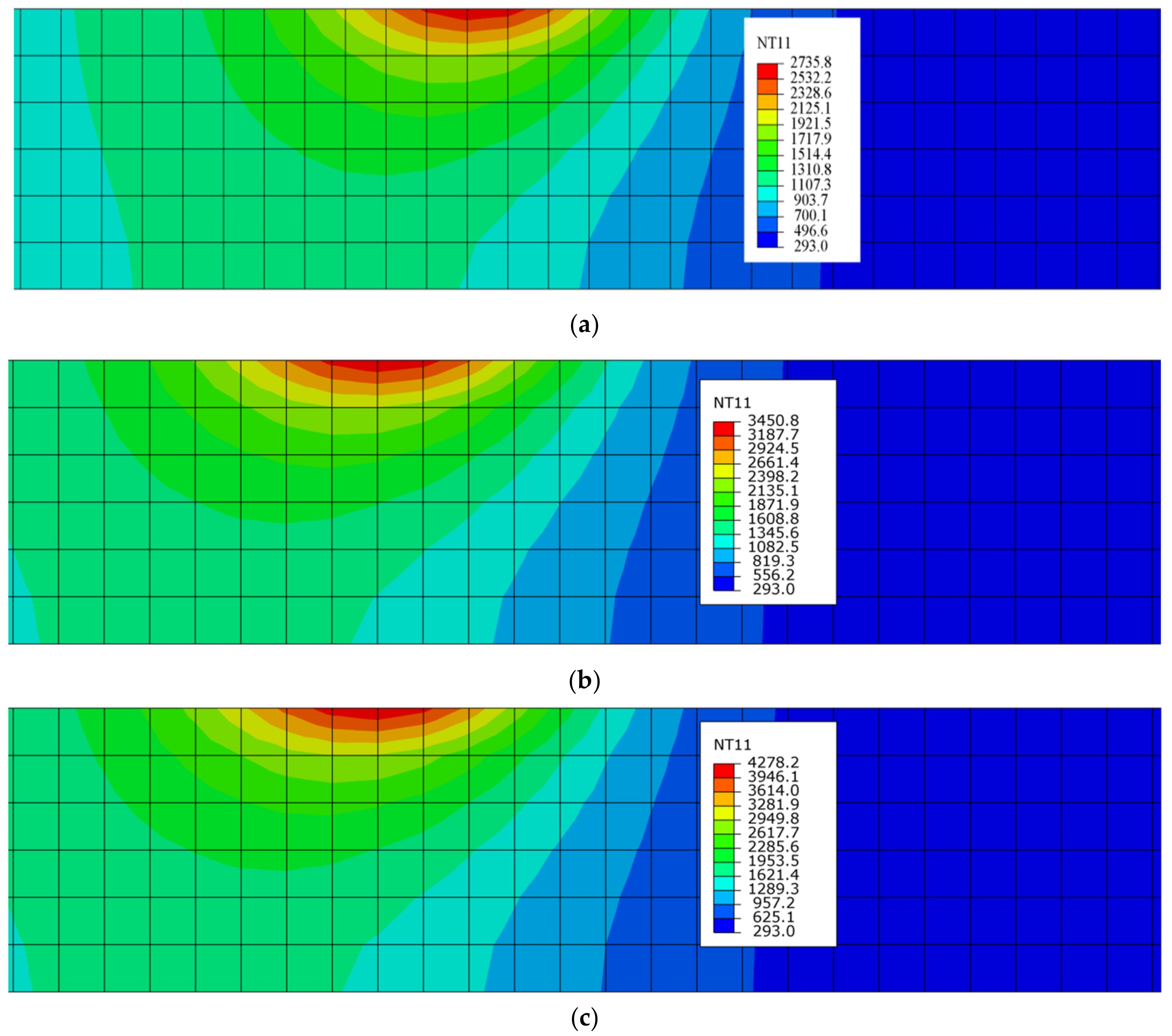
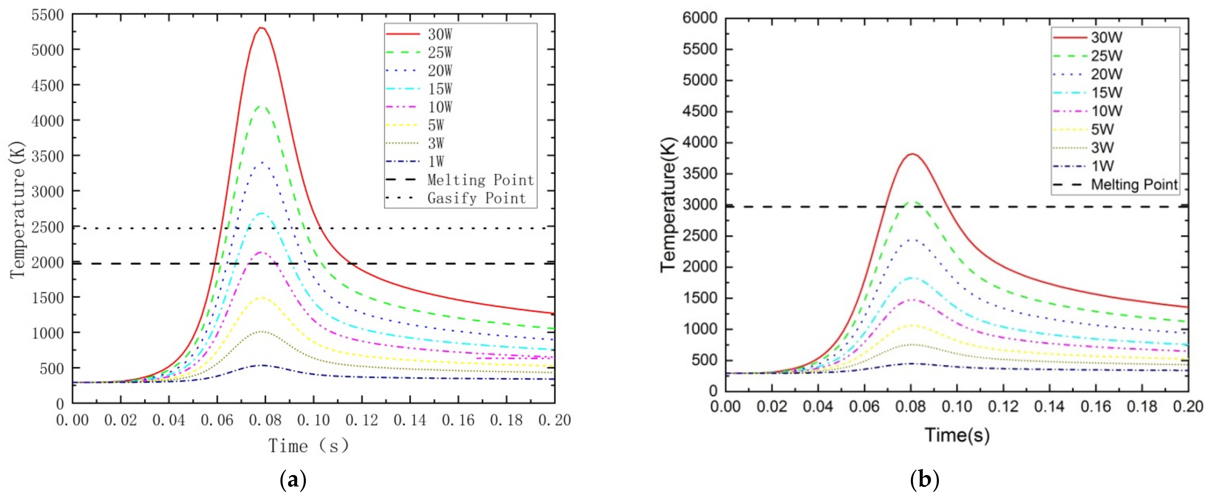
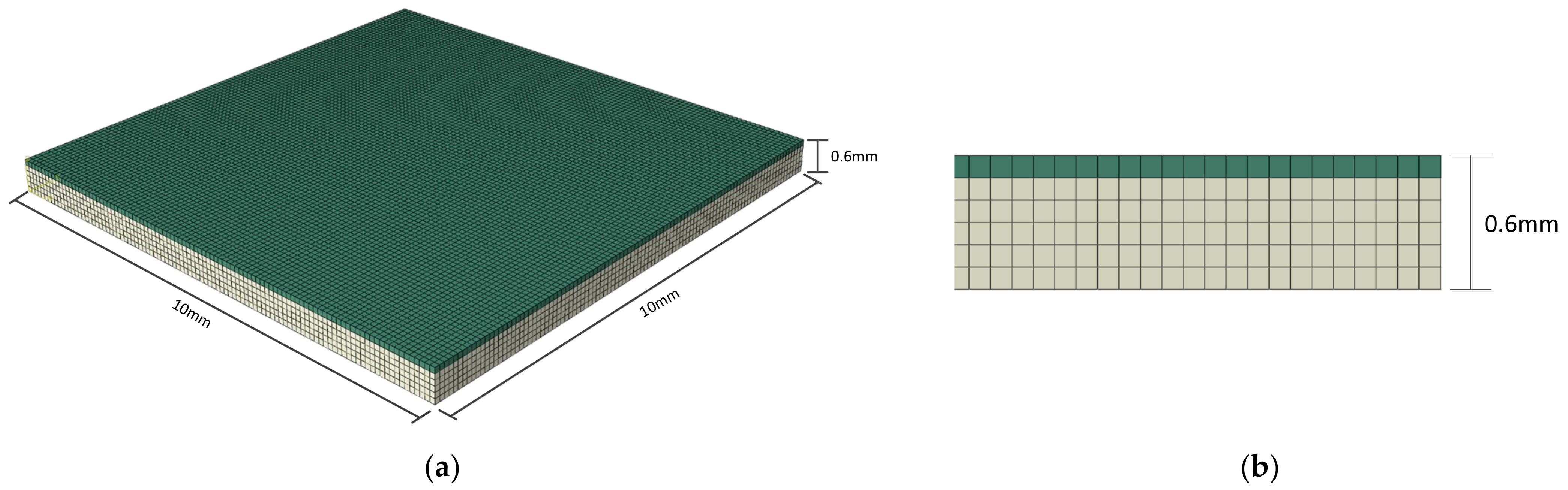
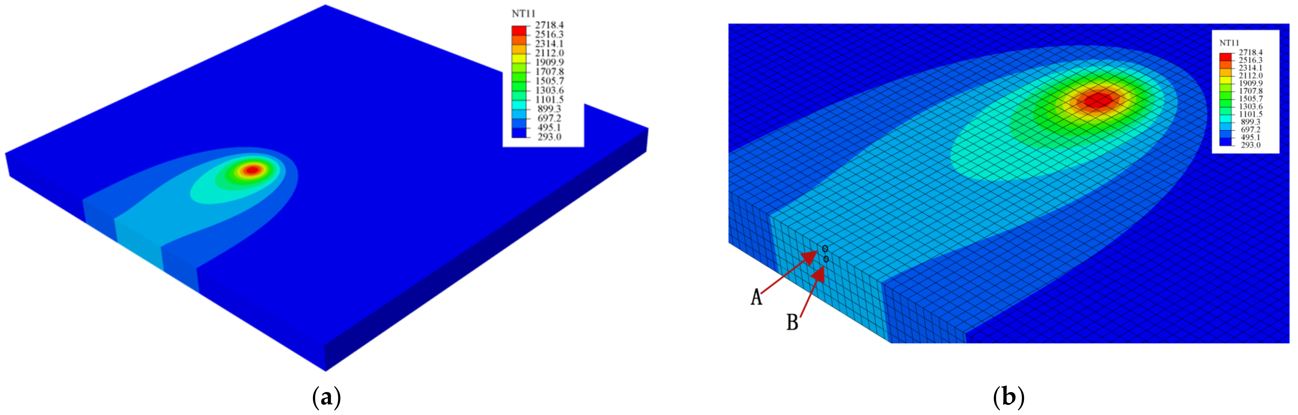
2.3. Temperature Simulation and Analysis

The temperature dissipation simulation of the laser cleaning strategy was similar to previous studies [47]. During the laser cleaning simulation process, the parameters of conductivity, density, specific heat, and expansion coefficient were defined using Abaqus software. The nanosecond green laser pulse width was 25 ns, which determines one of most important thermo-physical parameters—the thermal diffusion length. The numerical simulation parameters of laser cleaning are shown in Table 2.
The finite element model and mesh division of the laser cleaning sample are shown in Figure 3. Tetrahedral meshing was used, and the mesh size was set to 0.1 mm. The thickness of the whole silicon carbide was 0.6 mm, including the oxide layer of 0.1 mm thickness on the surface. In order to ensure the function of subsequent processes, the mesh quality should be checked after the completion of geometric modeling and mesh division to prevent excessive distortion in some areas. The finite element simulation mesh model of the laser cleaning sample SiC is shown in Figure 3a, and it is a finite element mesh division with 10 mm × 10 mm × 0.6 mm; the two-dimensional mesh temperature simulation is shown in Figure 3b. It can be seen from Figure 3 that the changes in temperature gradients are different in the point A and point B regions of the laser.
A simulation of the three-dimensional temperature field of SiC material based on Abaqus is shown in Figure 4. At point A, which is the highest point on the SiO2 surface, the temperature is 2230 degrees, which is greater than the boiling point B, where the silicon carbide meets the silicon oxide, at a depth of 0.1 mm from the top surface; this value is higher than the temperature change at point B, and it can be seen that the laser absorption of different materials is different.
Figure 5 shows the temperature distribution of point A at the same time under different power values; as can be seen from Figure 5a–c, with the input of different power values, the energy absorbed by the SiC material is different, resulting in a great difference in temperature change. Different colors represent different temperatures, with red being a hot zone of around 3000 °C and blue being a hot zone of 300 °C. The dark red color is the temperature distribution field, and the light color is the laser’s heat-affected zone. The heat-affected zone on the oxide layer on silicon carbide crystal is small. The laser cleaning temperature field describes the relationship between the temperature distribution and time at a given point in the silicon carbide. The temperature changes at various laser cleaning depths from the surface at different energy densities.
The laser cleaning process of silicon carbide material was simulated and calculated, and the resulting temperature change is shown in Figure 6. Figure 6a shows the temperature curve of point A at the contact position between surface impurities and silicon carbide. The temperature curve changes under different powers; meanwhile, when the input power reaches more than 10 W, the temperature of the silicon carbide surface oxide layer reaches the melting point of 2000 K. When the input power reaches more than 15 W, the gasification point is reached, and the surface oxide particles are vaporized. Based on the physical and chemical characteristics of the materials, we know that the surface temperature of the gasification at 2500 K, which is lower than the melting point of SiC, cannot be completely removed. Figure 6b shows the curve representing the temperature of point B under different power values. When the surface temperature of SiO2 is more than 2500 K, the surface impurities start to break down, but due to the low light energy, they reach the surface impurities decomposition threshold line. In addition, after laser action on the oxide layer, heat is transferred downward to silicon carbide, and the temperature of the silicon carbide base material changes. As shown in the figure, when the scanning speed is 1500 mm/s and the laser power is 25 W, the dotted line is the cleaning threshold temperature line, which can be used as the cleaning threshold of the material, therefore, the surface impurities are cleaned. When the temperature is higher than 25 W, the cleaning degree of SiC gradually increases, and when the temperature is higher than the surface layer, the ablation pit appears.

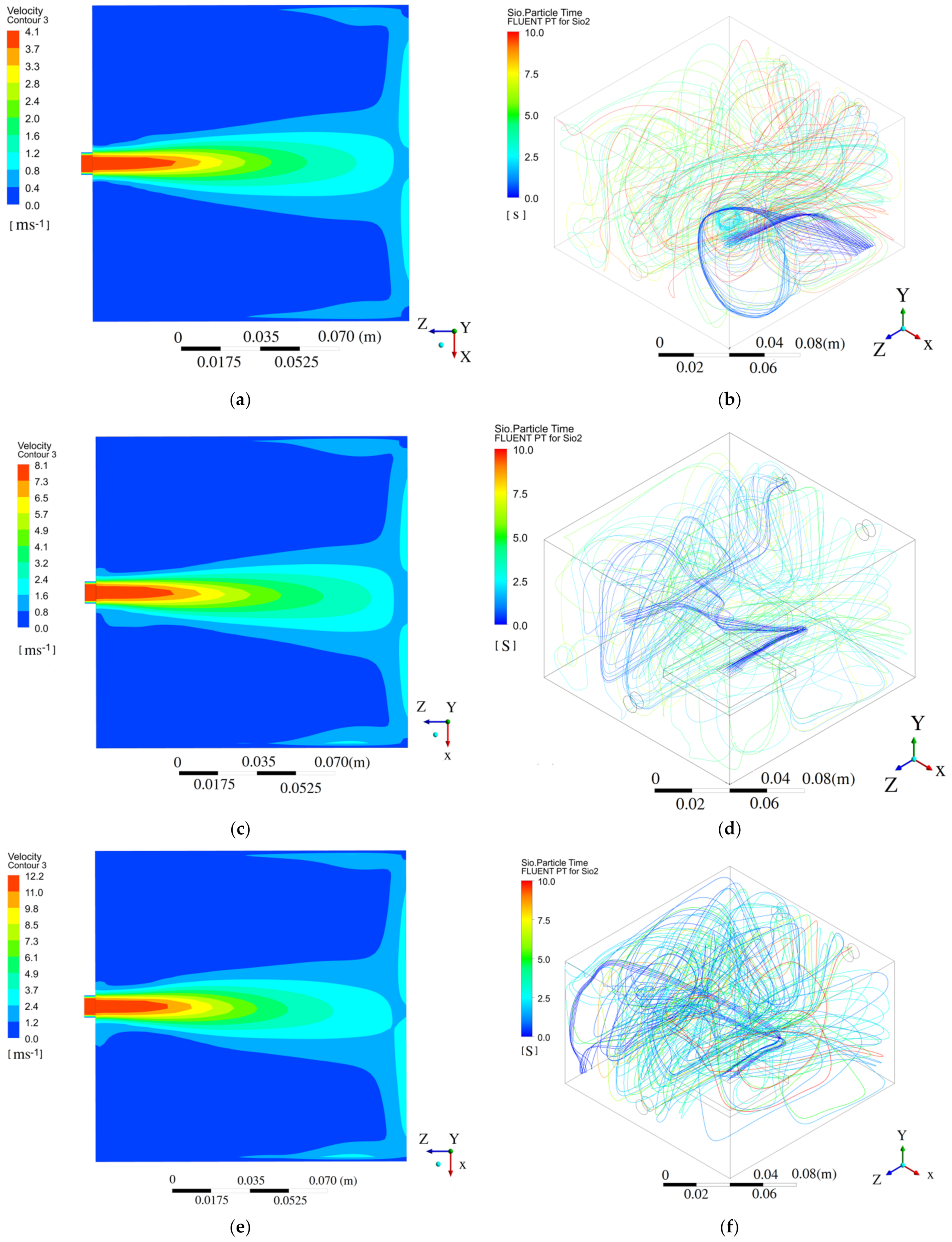
2.4. Dust Particle Simulation

Fluent software was used to simulate a dynamics analysis of the laser cleaning method used on the particles, to simulate particle motion and distribution, and to study the flow field distribution in the cleaning seal cavity. It was also used to simulate the flow characteristics of laser cleaning particles and to explore the flow characteristics of laser cleaning particles. Calculations were based on the steady flow of an incompressible fluid, which had a nitrogen density of 1.25 kg/m3. According to the requirements of the pressure boundary setting, the intake pipe was the speed inlet, and the outlet was the pressure outlet. Velocity vector diagrams are an effective means to reflect the internal velocity changes and vortices of laser cleaning in the particle flow field, and they also represent a common method to reflect the overall trend of a particle flow field. The SiO2 particle distribution and flow velocity under 0.15 Mpa, 0.2 Mpa, and 0.25 Mpa were simulated, respectively. According to the simulation results in Figure 7a,b, the cleaning particles are mainly Si and SiO2. The particle air flow flows in from the inlet, and the velocity behind the wall is 4.2 m/s. The exhaust port is set in the opposite direction to the intake port, and the air flow gradually weakens when it reaches the outlet port. It can be seen from Figure 7c,d that the inlet speed reaches 8.1 m/s, and in Figure 7e,f, the inlet speed reaches 12.2 m/s.

3. Experimental Equipment and Method

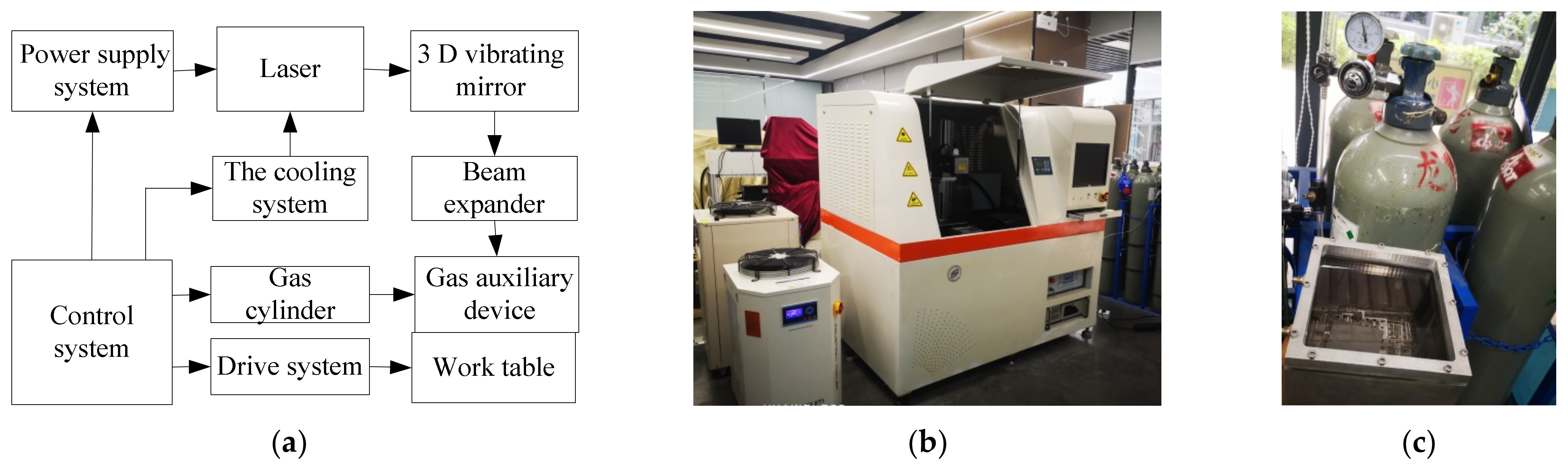
3.1. Experimental Equipment

The testbed consisted of a nanosecond green laser, a control system, a cooling system, a 3D vibrating mirror, an optical path system, a working system, a gas auxiliary device, etc. The maximum power of the laser was 30 W. A schematic diagram of the laser cleaning equipment is shown in Figure 8. Figure 8a is a schematic diagram of laser cleaning assisted by airflow, Figure 8b is a photograph of the laser cleaning equipment assisted by airflow, and Figure 8c is a photograph of the gas auxiliary device, a gas chamber that can provide 0 to 1 Mpa gas pressure and which is controlled by a cylinder.

3.2. Test Materials, Laser Cleaning Parameters, and Methods

SiC materials were selected for the experiment, and the auxiliary gas was nitrogen. The size of the experimental sample was 40 mm × 40 mm × 0.6 mm, where 0.6 mm is the thickness of silicon carbide, and the thickness of the silicon carbide surface oxide particles was 0.1 mm. The nanosecond green laser cleaning parameters were as follows: the laser wavelength was 532 nm, the nanosecond green laser power was 30 W, the repetition frequency was 100 kHz, the beam quality M2 was 1.3. The spot size of the laser beam was 0.8 ± 0.2 mm, and the line spacing (hatch) was 0.03 mm. With the exception of the spot irradiation and scanning speed, the surface laser cleaning method was similar to previous research [48,49], and the cleaning parameters were optimized and are provided in Table 3. To clean the material more rapidly, the scanning speed was set up higher than previous works [50,51,52]. After the experiment, the surface cleaning precision of the samples was observed and measured via SEM and an optical microscope. The filter values from the roughness measurements were used to test roughness. The filtering parameters were Gaussian (ISO 16610-61) and used for the surface analysis. The cleaned layer was characterized using a roughness measurement tool (Mahr MarSurf CM mobile and Bruker) and SEM (Zeiss Gemini SEM 300, Carl Zeiss, Germany). EDS tests were used to judge the change in the elements before and after cleaning to the degree of oxidation layer cleaning.

4. Results and Discussion

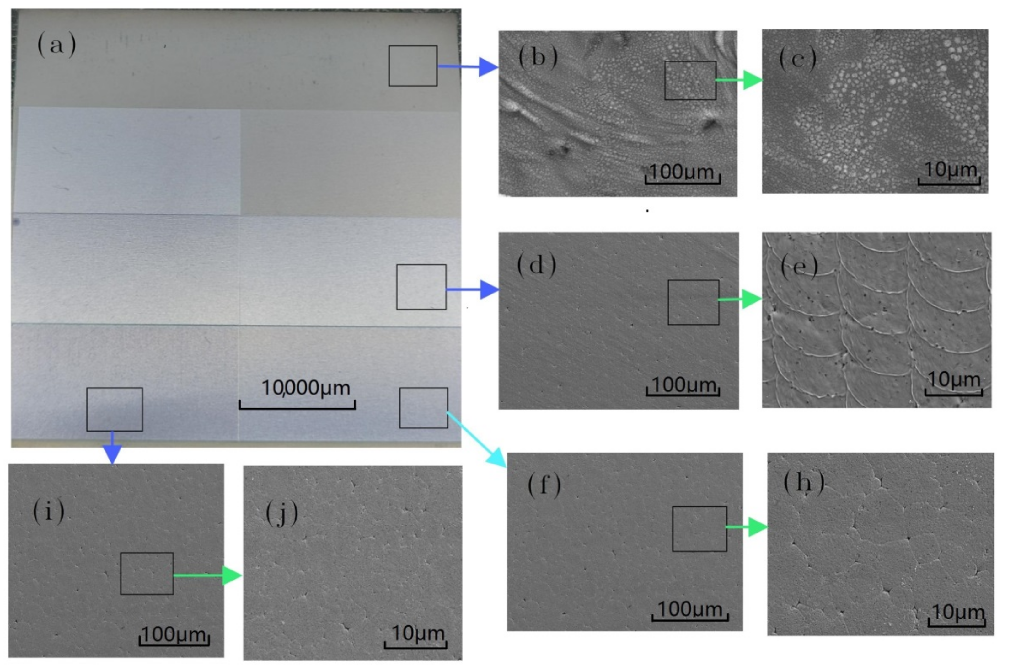
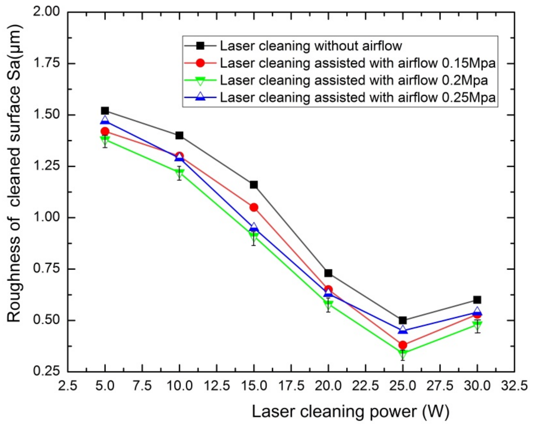
4.1. Influence of the Laser Cleaning

The power and scanning speed affect the quality of SiC cleaning, and laser energy is the main energy source in SiC laser cleaning. It can be seen from Figure 9 that under the scanning condition of 1500 mm/s, the laser cleaning power varies from 10 to 30 W, and the roughness of the cleaning surface changes. The roughness decreases with the increase in power, and when the power is reduced to a certain extent, the excessive power will increase. According to some studies [53,54], the surface roughness after laser cleaning is a very important evaluation index. From a trend perspective, after the addition of the air flow assist system, compared with no gas assist system, laser cleaning has a lower cleaning roughness and higher cleaning quality. This is because the gas accelerates the cleaning speed, the surface particles have a higher efficiency, and the surface roughness is reduced. From the numerical point of view, the particle removal efficiency is different under different gas pressures, and the cleaning quality under 0.2 Mpa is better than other gas-assisted pressures. The measurement error of the laser cleaning roughness with gas assistance is marked in Figure 9 at 0.2 Mpa. Combined with the light microscope, it can be seen that the air-assisted system has no effect on the base damage threshold. Laser cleaning assisted with an airflow of 0.2 Mpa is shown in Figure 9 to reveal the error bars of roughness. When the power reaches 30 W, it is greater than the energy threshold, the cleaning surface evaporation is intense, the substrate is partially damaged, the surface quality will therefore decline, and the surface roughness value will rise.

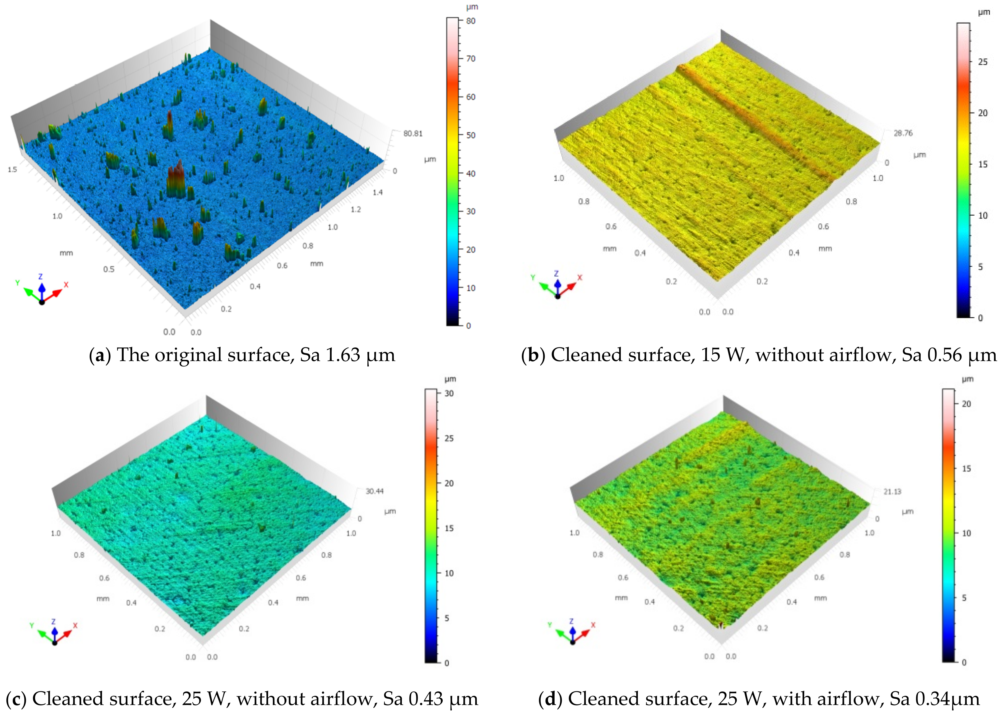
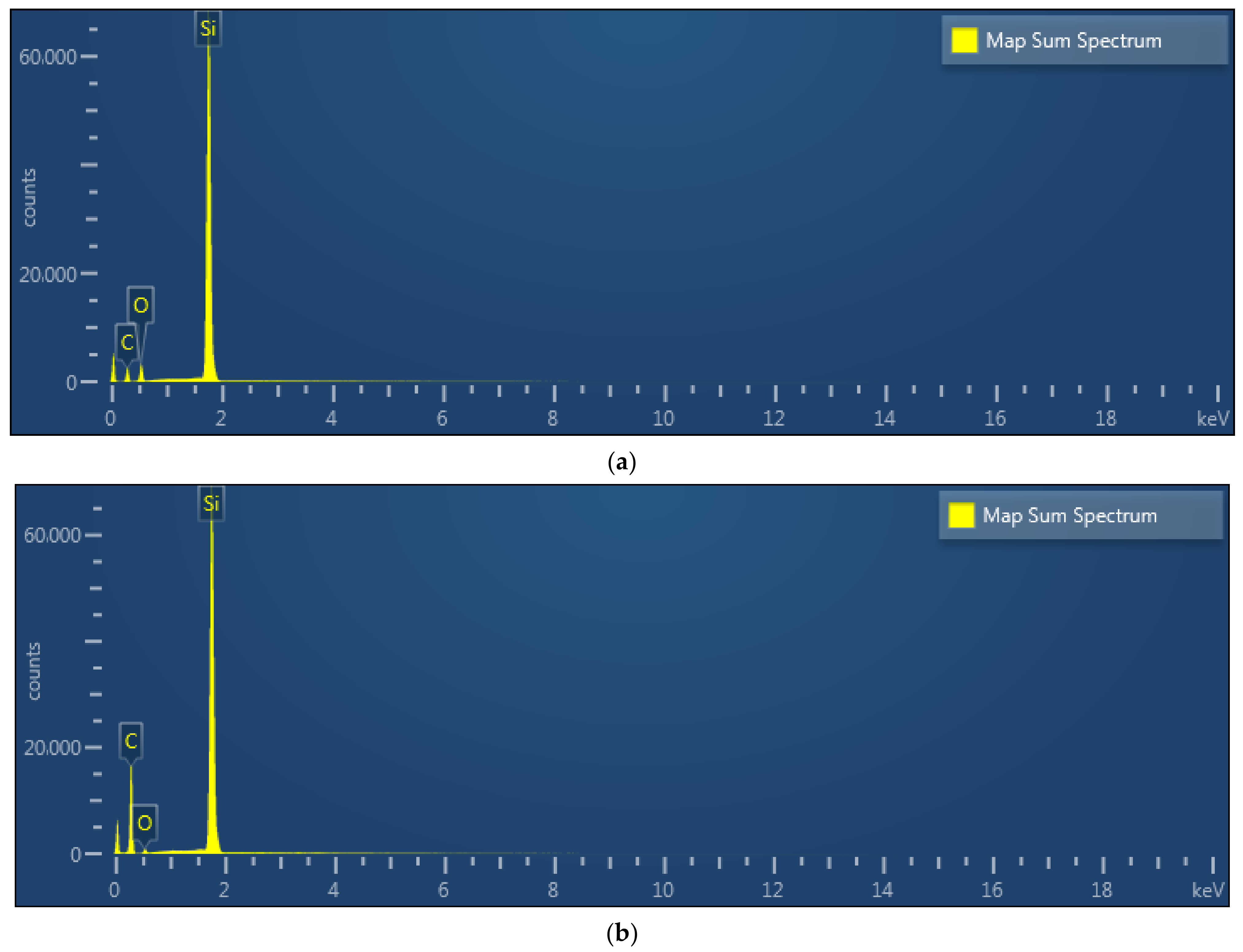
4.2. Test for Laser Cleaning

After optimizing the laser cleaning process parameters, the test of the three-dimensional morphology of the matrix surface under different laser cleaning power values is shown in Figure 10. The three-dimensional morphology of the sample surface is shown after the silicon carbide surface was cleaned using lasers with different power at 1500 mm/s scanning speed. Sa is the roughness based on the cleaning regional topography, which was found to be as high as 0.53 μm, with an initial roughness of 1.63 μm. After a 15 W power was used to clean the surface of the ceramic matrix, there were a few uneven micropits on the surface of the ceramic matrix. After using 20 W laser cleaning, the surface of the ceramic matrix formed a uniform groove morphology of 2 μm. After laser cleaning with an energy density of 30 W, the wave peak of the groove increased due to different degrees of serious melting phenomenon. The experimental results show that when the laser power is 25 W, the scanning speed is 1500 mm/s, and the lap rate is 50%, the surface of the silicon carbide matrix is 0.2 μm, which is essentially consistent with the simulation results, indicating that this combination of cleaning parameters can obtain a good surface in line with the cleaning effect.
Figure 11 shows the SEM of the SiC matrix after laser cleaning using gas under different power values. Figure 11b,c are the SEM images of the original surface, and many surface microparticles can be seen through magnification (Figure 11c); the oxide layer and microparticles on the silicon carbide crystal can been seen under different magnifications. When the laser is low at 5 W, as shown in Figure 11d,e, there is a layer of microparticles on the surface of the matrix, which is not completely clean. When the laser energy density is 25 W, there is no residual particle material on the matrix surface, and the cleaning effect is better in this instance. The surface of the matrix is completely ablated and appears to be molten (Figure 11f,h). The splashing of molten material caused by laser ablation and the grooves after laser scanning can clearly be observed on both sides of the scanning path, but there are still material particles adhering to the substrate surface. SEM images of SiC substrate after cleaning at 25 W and a gas pressure of 0.2 Mpa are shown in Figure 12i,j, demonstrating an excellent cleaning effect. Under low power, the scanning corrugated path (the ripples) can be seen, as shown in Figure 11e. With the increase of laser power, the cleaning surface becomes smoother, as shown in Figure 11h,j. With the assistance of gas, the surface is cleaner after laser cleaning, it is efficiently removing the oxide layer on silicon carbide crystal using a nanosecond green laser without damaging the SiC substrate, and the flow of particles on the surface is accelerated under the assistance of gas.
The surface of the sample according to EDS before and after laser cleaning is shown in Figure 12a,b. The content of O significantly decreased, from 10 to about 1.91%. After nanosecond green laser cleaning assisted with airflow, the content of O in the cleaned surface is very low, indicating that the basic effective cleaning of SiO2 is removed, also indicating that the SiO2 oxide layer [54] is greatly reduced, according to the content of the pure silicon carbide element. This is very close to the composition of pure silicon carbide, in which the content of C is 30% and the content of Si is 70%, indicating that the gas-assisted laser cleaning method is effective. The reduction of the oxide components of the silicon carbide crystal substrate means that oxidation layers are removed via nanosecond green laser cleaning.

5. Conclusions

The simulation of the laser cleaning temperature field and dust particle simulation provided guidance for the experiment and was consistent with experimental results for laser cleaning. Laser cleaning flow assisted with a silicon carbide ceramic crystal material surface oxide layer and microparticles is original innovative research. Firstly, the influence of moving nanosecond pulse laser parameters on the surface temperature field of the silicon carbide material and dust particle simulation were analyzed based on simulation software. On this basis, an experimental study was conducted on the surface morphology of silicon carbide crystal microparticles using nanosecond green laser cleaning assisted with airflow. The simulation and experimental results were essentially consistent, which verified the rationality of the established finite element model simulation. Laser cleaning silicon carbide assisted by airflow was achieved through the thermal effect produced via the nanosecond green laser. The SiO2 particle distribution and flow velocity under 0.15 Mpa, 0.2 Mpa, and 0.25 Mpa were simulated, respectively. Laser cleaning simulation provides a reference for the experiment. More importantly, this is a method of airflow-assisted nanosecond green laser cleaning of microparticles, and the oxide layer on silicon carbide crystal decreased, and its surface roughness decreased from over 1.63 to less than 0.35 µm.

Author Contributions

Conceptualization, H.X. and C.D.; methodology, C.D. and S.Z.; investigation, H.X.; writing—original draft preparation, H.X. and S.Z.; writing—review and editing, C.D. and Y.Z.; supervision, Y.Z. All authors have read and agreed to the published version of the manuscript.

Funding

This work was financially supported by the Science and Technology Project of Guangdong Province (grant no. 2021A0505030013), the Scientific Research Project of General Universities in Guangdong Province (grant nos. 2021KCXTD058, 2022ZDZX3073), and the Scientific research Project of Shenzhen Institute of Information Technology (grant no. SZIIT2022KJ075, HX-0440, HX-0441).

Data Availability Statement

The data underlying the results presented in this paper are available upon request by contact with the corresponding author.

Acknowledgments

We would like to acknowledge the contributions of the theory of laser cleaning and the removal process of Silicon carbide materials to this paper.

Conflicts of Interest

The authors declare no conflict of interest.

References

  1. Chowdhury, E.H.; Rahman, M.H.; Hong, S. Tensile strength and fracture mechanics of two-dimensional nanocrystalline silicon carbide. Comput. Mater. Sci. 2021, 197, 110580. [Google Scholar] [CrossRef]
  2. Huang, D.; Tan, R.; Liu, L.; Ye, C.; Zhu, S.; Fan, Z.; Zhang, P.; Wu, H.; Han, F.; Liu, H.; et al. Preparation and properties of the three-dimensional highly thermal conductive carbon/carbon-silicon carbide composite using the mesophase-pitch-based carbon fibers and pyrocarbon as thermal diffusion channels. J. Eur. Ceram. Soc. 2021, 41, 4438–4446. [Google Scholar] [CrossRef]
  3. Zhou, J.; Wang, C.; Song, M.; Chen, X.; Xia, W. Simple synthesis of ultrafine amorphous silicon carbide nanoparticles by atmospheric plasmas. Mater. Lett. 2021, 299, 130072. [Google Scholar] [CrossRef]
  4. Pan, Y.; Zhao, Q.; Guo, B.; Long, Y. High-efficiency machining of silicon carbide Fresnel micro-structure based on improved laser scanning contour ablation method with continuously variable federate- ScienceDirect. Ceram. Int. 2020, 47, 4062–4075. [Google Scholar] [CrossRef]
  5. Tam, A.C.; Park, H.K.; Grigoropoulos, C.P. Laser cleaning of surface contaminants. Appl. Surf. Sci. 1998, 127–129, 721–725. [Google Scholar] [CrossRef]
  6. Klein, S.; Fekrsanati, F.; Hildenhagen, J.; Dickmann, K.; Uphoff, H.; Marakis, Y.; Zafiropulos, V. Discoloration of marble during laser cleaning by Nd: YAG laser wavelengths. Appl. Surf. Sci. 2001, 171, 242–251. [Google Scholar] [CrossRef]
  7. Zheng, Y.W.; Luk’Yanchuk, B.S.; Lu, Y.F.; Song, W.D.; Mai, Z.H. Dry laser cleaning of particles from solid substrates: Experiments and theory. J. Appl. Phys. 2001, 90, 2135–2142. [Google Scholar] [CrossRef] [Green Version]
  8. Fieret, J.; Batta, N.; Lu, Y.; Wang, X.; Shi, J.; Thompson, D.W.; Doerr, D.W.; Alexander, D.R. Monitoring steam laser cleaning using optical probe techniques. Proc. SPIE 2005, 5713, 436–445. [Google Scholar]
  9. Allcock, D.T.C.; Guidoni, L.; Harty, T.P.; Ballance, C.J.; Blain, M.G.; Steane, A.M.; Lucas, D.M. Reduction of heating rate in a microfabricated ion trap by pulsed-laser cleaning. New J. Phys. 2011, 13, 814–823. [Google Scholar] [CrossRef]
  10. Samolik, S.; Walczak, M.; Plotek, M.; Sarzynski, A.; Pluska, I.; Marczak, J. Investigation into the removal of graffiti on mineral supports: Comparison of nano-second Nd: YAG laser cleaning with traditional mechanical and chemical methods. Stud. Conserv. 2015, 60, 58–64. [Google Scholar] [CrossRef] [Green Version]
  11. Kelley, J.D.; Hovis, F.E. A Thermal detachment mechanism for particle removal from surfaces by pulsed laser irradiation. Microelectron. Eng. 1993, 20, 159–170. [Google Scholar] [CrossRef]
  12. Kanazawa, Y.; Sawada, A.; Zhao, W.; Jarupoonphol, W.; Takai, M. Wavelength dependence of UV laser cleaning for silicon field emitter arrays. Jpn. J. Appl. Phys. 2003, 42, 196–197. [Google Scholar] [CrossRef]
  13. Jette, A.N.; Benson, R.C. Modeling of pulsed-laser cleaning of metal optical surfaces at cryogenic temperatures. J. Appl. Phys. 1994, 75, 3130–3141. [Google Scholar] [CrossRef]
  14. Zapka, W.; Ziemlich, W.; Leung, W.P.; Tam, A.C. Laser cleaning: Laser-induced removal of particles from surfaces. Adv. Funct. Mater. 2010, 2, 63–70. [Google Scholar] [CrossRef]
  15. Harris, C.D.; Shen, N.; Rubenchik, A.M.; Demos, S.G.; Matthews, M.J. Characterization of laser-induced plasmas associated with energetic laser cleaning of metal particles on fused silica surfaces. Opt. Lett. 2015, 40, 5212. [Google Scholar] [CrossRef]
  16. Kim, J.E.; Han, M.S.; Kim, J.D. Removal characteristics of shop-primer paint by laser energy density in Q-switching fiber laser cleaning. Mod. Phys. Lett. B 2020, 34, 2040042. [Google Scholar] [CrossRef]
  17. Lu, Y.F.; Zheng, Y.W.; Song, W.D. Laser induced removal of spherical particles from silicon wafers. J. Appl. Phys. 2000, 87, 1534–1539. [Google Scholar] [CrossRef]
  18. Lu, Y.F.; Zheng, Y.W. Characterization of ejected particles during laser cleaning. J. Appl. Phys. 2000, 87, 549–552. [Google Scholar] [CrossRef]
  19. Ling, X.; Wang, G.; Zhang, C. Investigation of laser cleaning on bronze cultural relics. Laser Phys. 2016, 26, 055603. [Google Scholar] [CrossRef]
  20. Wang, F.; Ai, S.; Wang, Q.; Cheng, Y.; Huang, H.; Cai, C.; Xie, D.; Chen, H.; Hu, W. Effect of narrow pulse width laser cleaning on corrosion resistance of A5083-H111 aluminum alloy. Anti-Corrosion Methods Mater. 2021, 68, 192–201. [Google Scholar] [CrossRef]
  21. Kumar, A.; Biswas, D. Particulate size and shape effects in laser cleaning of heavy metal oxide loose contamination off clad surface. Opt. Laser Technol. 2018, 106, 286–293. [Google Scholar] [CrossRef]
  22. Guo, L.; Li, Y.; Geng, S.; Wang, C.; Jiang, P. Numerical and experimental analysis for morphology evolution of 6061 aluminum alloy during nanosecond pulsed laser cleaning. Surf. Coat. Technol. 2022, 432, 128056. [Google Scholar] [CrossRef]
  23. Zheng, Y.W.; Lu, Y.F.; Song, W.D. Angular effect in laser removal of spherical silica particles from silicon wafers. J. Appl. Phys. 2001, 90, 59–63. [Google Scholar] [CrossRef]
  24. Leiderer, P.; Mosbacher, M.; Döbler, V.; Schilling, A.; Yavas, O.; Luk’Yanchuk, B.S.; Boneberg, J. Steam laser cleaning of silicon surfaces: Laser-induced gas bubble nucleation and efficiency measurements. In Laser Cleaning; Luk’Yanchuk, B., Ed.; World Scientific Publishing Co. Pte. Ltd.: Singapore, 2002; pp. 255–310. [Google Scholar]
  25. Wan, Z.; Yang, X.; Xia, G.; Li, D.; Liu, W.; Cheng, J.; Wang, S. Effect of laser power on cleaning mechanism and surface properties. Appl. Opt. 2020, 59, 9482–9490. [Google Scholar] [CrossRef] [PubMed]
  26. Kennedy, C.; Vest, M.; Cooper, M.; Wess, T.J. Laser cleaning of parchment: Structural, thermal and biochemical studies into the effect of wavelength and fluence. Appl. Surf. Sci. 2004, 227, 151–163. [Google Scholar] [CrossRef]
  27. Lee, J.M.; Watkins, K.G. Removal of small particles on silicon wafer by laser-induced airborne plasma shock waves. J. Appl. Phys. 2001, 89, 6496–6500. [Google Scholar] [CrossRef]
  28. Siano, S.; Salimbeni, R. Advances in Laser Cleaning of Artwork and Objects of Historical Interest: The Optimized Pulse Duration Approach. Am. Chem. Soc. 2010, 43, 739–750. [Google Scholar] [CrossRef]
  29. Kim, J.E.; Kim, J.D. A study on the removal of paint and oxide layer on the steel surface by laser beam scanning method. Int. J. Mod. Phys. B 2021, 35, 2140006. [Google Scholar] [CrossRef]
  30. Chen, T.; Wang, W.; Tao, T.; Pan, A.; Mei, X. Multi-scale micro-nano structures prepared by laser cleaning assisted laser ablation for broadband ultralow reflectivity silicon surfaces in ambient air. Appl. Surf. Sci. 2020, 509, 145182. [Google Scholar] [CrossRef]
  31. Zhang, S.; Yan, Q.; Lin, J.; Zhang, Q.; Lu, Y.; Yao, J.; Fan, L. Elimination of blind zone in nanoparticle removal on silicon wafers using a double-beam laser shockwave cleaning process. Appl. Surf. Sci. 2020, 539, 148057. [Google Scholar] [CrossRef]
  32. Liu, Y.; Liu, W.; Zhang, D.; Tian, Z.; Sun, X.; Wei, Z. Experimental investigations into cleaning mechanism of ship shell plant surface involved in dry laser cleaning by controlling laser power. Appl. Phys. A-Mater. Sci. Process. 2020, 11, 886. [Google Scholar]
  33. Zhu, G.; Xu, Z.; Jin, Y.; Chen, X.; Yang, L.; Xu, J.; Shan, D.; Chen, Y.; Guo, B. Mechanism and application of laser cleaning: A review. Opt. Lasers Eng. 2022, 2022, 107130. [Google Scholar] [CrossRef]
  34. Ye, Y.; Yuan, X.; Xiang, X.; Cheng, X.; Miao, X. Laser cleaning of particle and grease contaminations on the surface of optics. Opt.-Int. J. Light Electron. Opt. 2012, 123, 1056–1060. [Google Scholar] [CrossRef]
  35. Milles, S.; Soldera, M.; Kuntze, T.; Lasagni, A.F. Characterization of self-cleaning properties on superhydrophobic aluminum surfaces fabricated by direct laser writing and direct laser interference patterning. Appl. Surf. Sci. 2020, 525, 146518. [Google Scholar] [CrossRef]
  36. Chen, E.Y.; Renner, P.; Lee, K.; Guo, B.; Liang, H. Effects of humidity on dust particle removal during solar panel cleaning. Surf. Topogr. Metrol. Prop. 2022, 10, 015003. [Google Scholar] [CrossRef]
  37. Ding, K.; Zhou, K.; Feng, G.; Han, J.; Xie, N.; Huang, Z.; Zhou, G. Mechanism and conditions for laser cleaning of micro and nanoparticles on the surface of transparent substrate. Vacuum 2022, 200, 110987. [Google Scholar] [CrossRef]
  38. Ghalamdaran, S.; Parvin, P.; Torkamany, M.J.; Zadeh, J.S. Two-dimensional simulation of laser ablation with 235 nanosecond pulses. J. Laser Appl. 2014, 26, 012009. [Google Scholar] [CrossRef]
  39. Ye, Y.; Yuan, X.; Xiang, X.; Dai, W.; Chen, M.; Miao, X.; Lv, H.; Wang, H.; Zheng, W. Laser plasma shockwave cleaning of SiO2 particles on gold film. Opt. Lasers Eng. 2010, 49, 536–541. [Google Scholar] [CrossRef]
  40. Yan, J.; Sakai, S.; Isogai, H.; Izunome, K. Characterization of microparticles and oxide layers generated by laser irradiation of diamond-machined silicon wafers. Semicond. Sci. Technol. Semicond 2011, 26, 025006. [Google Scholar] [CrossRef] [Green Version]
  41. Yan, J.; Takayama, N. Micro and Nanoscale Laser Processing of Hard Brittle Materials; Elsevier: Amsterdam, The Netherlands, 2020. [Google Scholar]
  42. Yan, J.W.; Asami, T.; Harada, H.; Kuriyagawa, T. Crystallographic effect on subsurface damage formation in silicon microcutting. CIRP Ann. 2012, 61, 131–134. [Google Scholar] [CrossRef]
  43. Patankar, N.; Joseph, D. Modeling and numerical simulation of particulate flows by the Eulerian–Lagrangian approach. Int. J. Multiph. Flow 2001, 27, 1659–1684. [Google Scholar] [CrossRef] [Green Version]
  44. Miyato, N. Particle flux and particle density source due to gyro-center heat source. Phys. Plasmas 2021, 28, 062304. [Google Scholar] [CrossRef]
  45. Chen, G.; Qiao, J. Femtosecond-laser-enabled simultaneous figuring and finishing of glass with a subnanometer optical surface. Opt. Lett. 2022, 47, 3860–3863. [Google Scholar] [CrossRef] [PubMed]
  46. Sahoo, P.K.; Feng, T.; Qiao, J. Dynamic pulse propagation modelling for predictive femtosecond-laser-microbonding of transparent materials. Opt. Express 2020, 28, 31103–31118. [Google Scholar] [CrossRef] [PubMed]
  47. Xiao, H.; Zhang, W.; Zhou, Y.; Liu, M.; Zhou, G. A Numerical Simulation and Experimental Study on the Ultrafast Double-Laser Precision Cutting of Sapphire Materials. Crystals 2022, 12, 867. [Google Scholar] [CrossRef]
  48. Hsu, S.C.; Lin, J. Removal mechanisms of micro-scale particles by surface wave in laser cleaning. Opt. Laser Technol. 2006, 38, 544–551. [Google Scholar] [CrossRef]
  49. Berthonneau, J.; Parent, P.; Grauby, O.; Ferry, D.; Laffon, C.; Colombini, A.; Courtois, B.; Bromblet, P. Yellowing of laser-cleaned artworks: Formation of residual hydrocarbon compounds after Nd:YAG laser cleaning of gypsum plates covered by lamp black. J. Cult. Herit. 2019, 39, 57–65. [Google Scholar] [CrossRef]
  50. Xu, J.; Wu, C.; Zhang, X.; Gao, F.; Yu, T.; Yuan, X. Influence of parameters of a laser cleaning soil rust layer on the surface of ceramic artifacts. Appl. Opt. 2019, 58, 2725–2730. [Google Scholar] [CrossRef]
  51. Ge, J.; Ge, J.; Liu, H.; Yang, S.; Lan, J. Laser Cleaning Surface Roughness Estimation Using Enhanced GLCM Feature and IPSO-SVR. Photonics 2022, 9, 510. [Google Scholar] [CrossRef]
  52. Chen, L.; Su, Y.; Zhang, J.; Zhang, H.; Fan, B.; Shao, G.; Zhong, M.; Wang, C.-A. Nanosecond Laser Cleaning Method to Reduce the Surface Inert Layer and Activate the Garnet Electrolyte for a Solid-State Li Metal Battery. ACS Appl. Mater. Interfaces 2021, 13, 37082–37090. [Google Scholar] [CrossRef]
  53. Huang, L.Q.; Zhu, Q.Z.; Gao, M.C.; Qin, F.W.; Wang, D.J. Cleaning of SiC surfaces by low temperature ECR microwave hydrogen plasma. Appl. Surf. Sci. A J. Devoted Prop. Interfaces Relat. Synth. Behav. Mater. 2011, 257, 10172–10176. [Google Scholar] [CrossRef]
  54. Zhao, H.; Qiao, Y.L.; Zhang, Q.; Du, X.; Zang, Y.; Liu, X.; Han, B.Y. Study on the characteristics and mechanism of pulsed laser cleaning of polyacrylate resin coating on aluminum alloy substrates. Appl. Opt. 2020, 59, 7053–7065. [Google Scholar] [CrossRef]
Figure 1. Structure of silicon carbide SiC (SiC) single-crystal material. (a) Photos of SiC crystal, (b) SiC crystal micrographs via microscope, (c) SiC covalent bonding.
Crystals 12 01788 g001
Figure 2. Schematic diagram of gas-assisted laser cleaning.
Crystals 12 01788 g002
Figure 3. Finite element model and mesh division of laser cleaning sample. (a) three-dimensional mesh, (b) two-dimensional mesh.
Crystals 12 01788 g003
Figure 4. Simulation of the three-dimensional temperature field of Sic material based on Abaqus. (a) Three-dimensional temperature field, (b) a larger version of temperature field.
Crystals 12 01788 g004
Figure 5. Simulation of the temperature field of silicon carbide crystal material based on Abaqus with varying laser powers at 0.08 s: (a) 15 W, 1500 mm/s; (b) 20 W, 1500 mm/s; (c) 25 W, 1500 mm/s.
Crystals 12 01788 g005
Figure 6. Heat transfer temperature curve of silicon carbide under different power values. (a) Surface impurities (silica, silicon) have a scanning speed of 1500 mm/s under different power temperature curve of point A. (b) Temperature curve of point B.
Crystals 12 01788 g006
Figure 7. Dust particle simulation under 0.15, 0.2, 0.25 Mpa. (a) SiO2 particle velocity under 0.15 Mpa, (b) SiO2 particle trajectories and distribution under 0.15 Mpa, (c) SiO2 particle velocity under 0.2 Mpa, (d) SiO2 particle trajectories and distribution under 0.2 Mpa, (e) SiO2 particle velocity under 0.25 Mpa, (f) SiO2 particle trajectories and distribution under 0.25 Mpa.
Crystals 12 01788 g007
Figure 8. Laser cleaning machine equipment. (a) Schematic diagram of laser cleaning, (b) photograph of the laser cleaning equipment, (c) gas auxiliary device.
Crystals 12 01788 g008
Figure 9. Roughness of cleaned surface varying with different laser cleaning powers.
Crystals 12 01788 g009
Figure 10. Three-dimensional morphology of matrix surface varying with different laser cleaning powers. (a) 3D roughness of original surface, (b) 3D roughness of cleaned surface under 15 W, without airflow, (c) 3D roughness of cleaned surface under 25 W, without airflow, and (d) 3D roughness of cleaned surface under 25 W, with airflow.
Crystals 12 01788 g010
Figure 11. SEM images of SiC substrate after laser cleaning with difference conditions. (a) Photo of silicon carbide after laser cleaning, (b) SEM images of the original surface, (c) Magnification SEM images of the original surface, (d) SEM images of the laser cleaning with laser power 5 W, (e) Magnification SEM images of the laser cleaning with 5 W, (f) SEM images of the laser cleaning under 25 W, (h) Magnification SEM images of the laser cleaning under 25 W, (i) SEM images of the laser cleaning at 25 W and with airflow, and (j) Magnification SEM images of the laser cleaning under 25 W and with airflow.
Crystals 12 01788 g011
Figure 12. EDS of silicon carbide crystal before and after laser cleaning. (a) EDS before laser cleaning, (b) EDS after laser cleaning assisted with airflow.
Crystals 12 01788 g012
Table 1. Physical and chemical parameters of SiC and microparticle on surface.
Test MaterialsCompositionMelting PointBoiling PointSpecific Gravity
SiC SubstrateSiC2827 °C3500 °C3.2 g/cm3
Oxide layer on surfaceSiO21723 ± 5 °C2230 °C2.2 g/cm3
Table 2. Numerical simulation parameters of laser cleaning.
ParametersNumerical Value of SiCNumerical Value of Microparticle on the Surface(SiO2)
Conductivity16.7 W/(M·K)0.27 W/(m K)
Density3200 Kg/(m3)2400 Kg/(m3)
Specific heat472.27 J/(Kg·K)700 J/(Kg·K)
Expansion coefficient4.5 × 10−6 K−10.5 × 10⁻⁶ K−1
Laser power 20, 25, 30 W; scanning speed, 1500 mm/s; pulse width, 25 ns
Table 3. Optimized parameters of laser cleaning processing parameters in each group.
Factor NameOptimized Value or Feature
Laser power (W) 51015202530
Scanning speed (mm/s)300600900120015001800
Pressure of the auxiliary gas0.15 Mpa; 0.2 Mpa; 0.25 Mpa
Cleaning ParametersWavelength: 532 nm; spot size of the laser beam: 0.8 ± 0.2 mm; hatch: 0.03 mm
Publisher’s Note: MDPI stays neutral with regard to jurisdictional claims in published maps and institutional affiliations.

