Article

Growth Mechanism of Ice Lens in Saturated Clay Considering Surface Charge

1
School of Civil Engineering and Architecture, Anhui University of Science and Technology, Huainan 232001, China
2
School of Resources and Environmental Engineering, Anhui University, Hefei 230601, China
*
Author to whom correspondence should be addressed.
Crystals 2022, 12(12), 1743; https://doi.org/10.3390/cryst12121743
Submission received: 3 November 2022 / Revised: 23 November 2022 / Accepted: 27 November 2022 / Published: 1 December 2022

Abstract

:
The main purpose of this study is to reveal the growth mechanism of ice lens in saturated clay. The deformation and fracturing of clay skeletons caused by ice crystal growth during the freezing process are gradually discussed, and a theoretical model for the whole process of ice lens growth considering the surface charge is proposed. Firstly, the electrical properties of clay surfaces and the pore structure characteristics of frozen clay are introduced, and the stress of pore walls during the growth of single pore ice crystals is calculated. Secondly, the values of parameters in the theoretical formula of separation pressure between adjacent clay particles are given when considering the linear elasticity of clay. Finally, the formation mechanism of the new lens is described, and the crack growth velocity equation is given. This paper shows that: there is a good consistency between the soil tensile strength of the macroscopic dimension and the intergranular separation pressure of the molecular dimension in judging the production conditions of the new lens; the formation of the new ice lens is the result of the destruction of the pore structure and the propagation of cracks caused by the growth of ice crystals, and more pore freezing can be caused only when the infiltration path of the ice crystals is formed in the pore structure. In order to verify the model, the ultimate compressive strength of soil calculated in this study was compared with the existing test results, and the rationality and correctness of the model are discussed. This study is of great significance to accurately understand the frost heave process.

1. Introduction

Ice lenses in frozen soil refer to the macroscopic ice layer that alternately appears perpendicular to the direction of the temperature gradient and soil. The formation and growth of ice lenses are not only closely related to the occurrence of frost heaving, the mechanical properties of frozen soil and the structural characteristics of frozen soil, but are also a great threat to the stability of buildings in cold regions [1].
Through the observations of a unidirectional freezing test of saturated soil in 1929, Taber [2] realized for the first time that the main cause of frost heave is the migration of water and the formation of ice lenses in the process of soil freezing. It has attracted many scholars to go deeply research into the microstructure of ice lenses. O’Neill et al. [3] proposed the theory of effective stress as ice lens formation based on the stress partition function, which laid a theoretical foundation for the study of the frost heaving mechanism. Ishizaki et al. [4] calculated the water velocity of frozen and unfrozen areas under different temperature gradients and external pressures by using a self-developed test device combined with X-ray technology and obtained the hydraulic conductivity of frozen soil under different conditions. Watanabe et al. [5] directly observed the ice structure near the ice lens with the method of a Raman spectrometer and a unidirectional freezing test using glass beads as the porous freezing medium and found that the growth position of the ice lens is the warmest end of the pores. Azmatch et al. [6] found that the soil crack formed before the ice lens through experiments and verified the correlation between the formation of a new ice lens and the existence of cracks. Watanabe et al. [7] combined the microscope with a unidirectional freezing device to observe the ice lens in saturated powder composed of uniform glass beads in situ and found that the growth rate of the ice lens was linearly related to the interface supercooling degree. Martin [8] and Konard et al. [9] proposed the theory of ice lens formation in fine-grained soil based on the unstable heat flux caused by water migration and the temperature change in the frozen fringe, and they believe that the formation of new lens is caused by the decrease in the actual temperature, which leads to the re-nucleation of ice crystals. However, You et al. [10] found that the interface undercooling was insufficient to meet the ice nucleation temperature by measuring the initial undercooling and solution nucleation undercooling of the new lens quantitatively, thus questioning the secondary nucleation mechanism of the ice lens.
In summary, although some achievements have been made in the growth of ice lenses, few studies have been conducted on the growth process of ice crystals in complex pores, and no consensus has been reached on the explanation of the formation mechanism of new ice lenses. Therefore, based on the formation process of new ice lenses in the complex pore structure of saturated clay, a theoretical model considering the whole process of ice lens growth under the action of a surface charge is proposed in this study by combining the colloidal interface mechanics and linear elastic fracture mechanics. Therefore, based on the formation process of the new ice lens in the complex pore structure of saturated clay, a theoretical model considering the whole process of ice lens growth under the action of a surface charge was proposed in this study by combining the colloidal interface mechanics and linear elastic fracture mechanics. The relationship between the nucleation position of ice crystals and the pore structure are analyzed from the molecular scale, and the initial conditions, growth and expansion of ice crystals and cracks in saturated clay during freezing are discussed. The relationship between the separation pressure between particles and the tensile strength of soil is clarified. The conditions for the initial crack and expansion of frozen clay are given, and the formation mechanism of frozen ice lenses of saturated clay is revealed. This research provides theoretical support for further study of the clay frost heave mechanism.

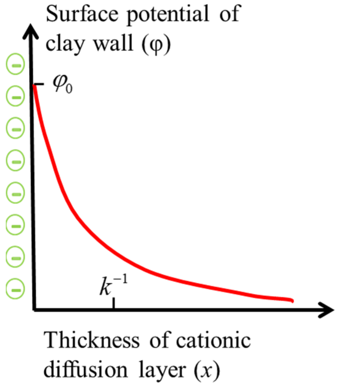
2. Electrical Properties of Clay Surface

In 1803, PeЙcc [11], a Russian scientist, found that there was a negative charge on the surface of clay particles through experiments. In the equilibrium solution, in order to maintain electrical neutrality, the clay surface will absorb a positive charge equal to the negative charge on its surface, resulting in a diffuse cationic solution layer on the clay surface, as shown in Figure 1. The charged interface on the clay surface and the locally distributed mobile positive charge form a double-layer structure, and according to the distance from the clay surface, the water in the soil can be divided into adsorbed water, capillary water and free water [12]. The ion concentration ci in the diffusion layer obeys the Boltzmann distribution [13]
c i = c 0 exp ( z e φ k B T ) ,
where c0 is the total number of positive and negative ions per unit volume of solution; z is the absolute value of positive and negative ions in the solution; e is the unit charge (e 1.60 × 10⁻¹⁹ C); φ is the electric potential, V; kB is the Boltzmann constant (kB 1.38 × 10⁻²³ J/K); T is the thermodynamic temperature, K.
The concentration of positive and negative ions in the solution can be expressed as
c = c 0 exp ( z e φ k B T ) c + = c + 0 exp ( z + e φ k B T ) } ,
Therefore, the total local charge density in the solution can be expressed as
ρ = z e ( c + c ) = 2 z e c 0 sinh ( z e φ k B T )
and when z e φ / k B T 1 ,
sinh ( z e φ k B T ) z e φ k B T ,
the relationship between the local charge density and the surface potential φ in the diffusion layer can be expressed by the Poisson equation
d 2 φ d x 2 = ρ ε ε 0 ,
where x is an axis perpendicular to the surface of the clay; ε is the dielectric constant of the solution, ε 78.4; ε 0 is the vacuum dielectric constant, ε 0 8.85 × 10⁻¹² F/m.
Substitution of Equations (3) and (4) into Equation (5)
d 2 φ d x 2 = k 2 φ ,
where k−1 is the Debye length, which represents the thickness of the diffusion layer
k 1 = ε ε 0 k B T 2 c 0 e 2 z 2 = ε ε 0 k B T 2 N A n 0 e 2 z 2 ,
and where NA is the Avogadro constant (NA 6.022 × 10²³ mol−1); n0 is the concentration of the amount of substance of ions, mol/m3.
By integrating Equation (6) twice, the electric potential at any distance x from the clay surface can be obtained as follows
φ = φ 0 e k x ,
where φ 0 is the surface potential of clay particles.
Based on the principle of electrical neutrality, it is known that the surface charge number of charged particles is equal to the local charge number in the diffused double layer, so the surface charge density ρ 0 of clay particles can be expressed as
ρ 0 = 0 ρ d x = ε ε 0 k φ 0 ,

3. Basic Assumptions and Physical Models

3.1. Basic Hypotheses

  • Saturated clay is regarded as an ideal elastoplastic porous medium without impurities;
  • The surface charge of clay particles is uniformly distributed and fixed, and the distribution law of the diffusion layer accords with the Boltzmann distribution;
  • There is only one symmetrical electrolyte in the solution, and the charge number of positive and negative ions is equal.

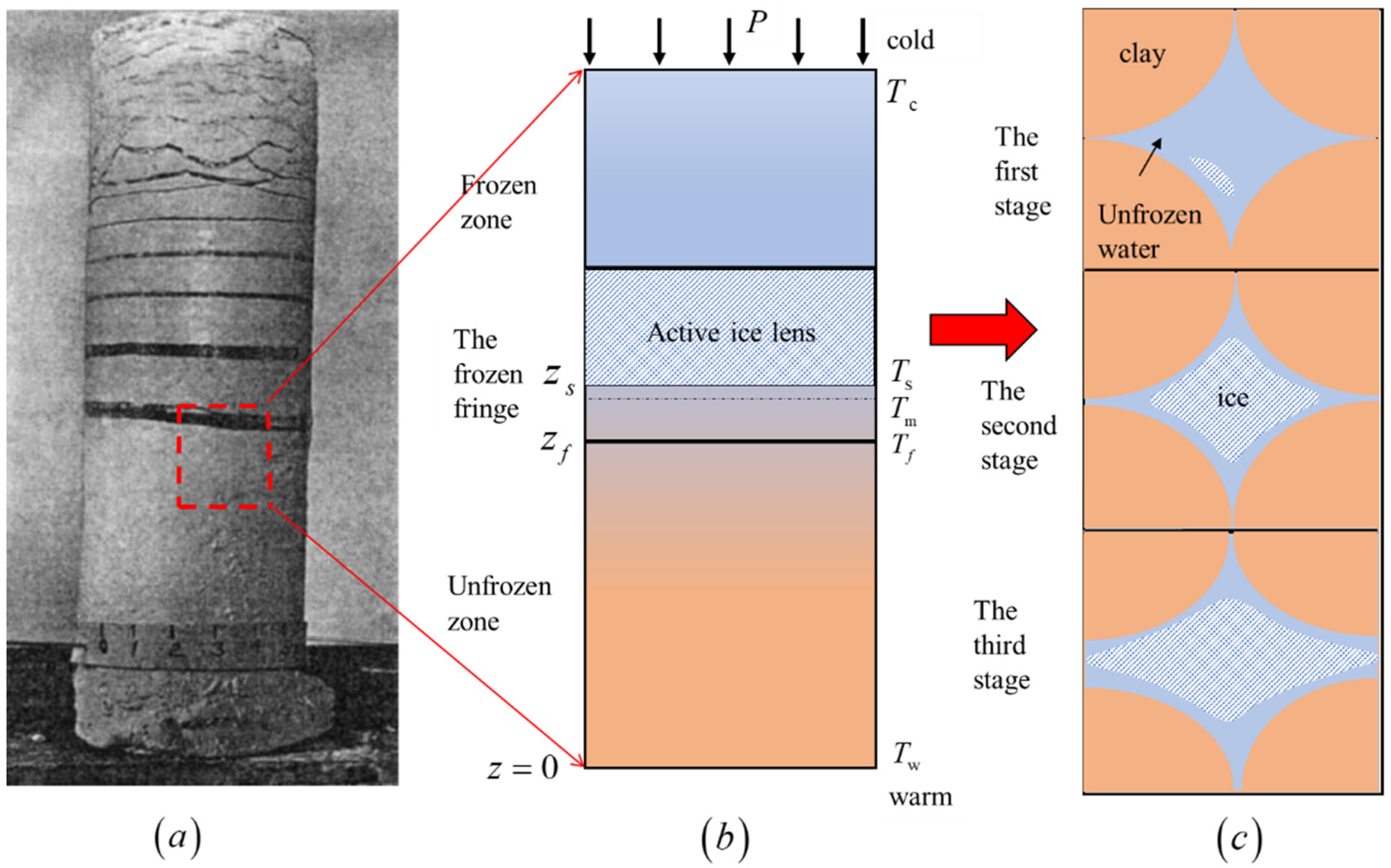
3.2. Growth Process Model of Ice Lens in Saturated Clay

In the case of a given temperature Tf and external pressure P, the soil mass in the one-dimensional freezing process is commonly divided into three areas [14,15]: a frozen zone, frozen fringe and unfrozen zone, as shown in Figure 2a,b.
In this study, large pores were selected as the research object, and the model as shown in Figure 2c was established. In this model, the freezing process of saturated clay was divided into three growth stages: in the first stage, when the temperature is lower than the freezing point Tic, the ice core forms on the clay surface [16] with large pores in the clay structure and grows gradually with the occurrence of freezing, and the pore water is discharged outward; in the second stage, due to the strong molecular force between the clay wall and the pore ice crystal, there is always an unfrozen water film between the ice and the clay wall, and the ice crystal continues to grow by constantly sucking water from the adjacent pores, and the volume of ice crystals in the pores continues to increase until the whole pore space is filled; in the third stage, the ice crystals filled with pores continue to grow, squeezing the surrounding clay skeleton, and when the local stress of the clay skeleton meets its local damage criterion, the adjacent clay is forced to separate and form cracks, and the ice crystals in the macro-pores gradually extend to the nearby pores through the soil cracks and finally form a new ice lens. As the freezing continues, these three states will continue to be repeated until the end of the cycle when the freezing conditions no longer meet the frost heave, resulting in the formation of the cryogenic structure of the periodic banded lens as shown in Figure 2a.

4. Mechanism of Ice Lens Growth in Saturated Clay

4.1. Pore Structure of Frozen Clay

The micropore structure of soil includes: basic particle arrangement, particle aggregation and pore space. The deformation of soil under the action of negative temperatures and a change in its mechanical properties are the reflection of the change in its microscopic pore structure at the macro level. Cheng et al. [17] found that, according to the size of soil pore size, soil samples are divided into three types: micropore when the pore diameter is less than 1 nm, mesoporous when the pore diameter is between 1 nm–100 nm, and macropore when the pore diameter is greater than 100 nm. In addition, the pore structure distribution of saturated silt before and after freezing and thawing was obtained by the LF–NMR test, as shown in Table 1.
The basic data of five different soils were measured by Dobson et al. [18], as shown in Figure 2. Jin et al. [19] verified the applicability of the electric double layer structure in conventional permafrost based on the set of measured data. In this study, the basic measured parameters were substituted into Equation (7) to calculate the cationic diffusion layer thickness k−1 of different charged soils in solution at the thermodynamic temperature of 273.15 K, as shown in Table 2.
As can be seen from Table 1, the pore distribution in the frozen soil sample is dominated by micro pores. Comparing the pore size distribution of soil samples calculated in Table 2 with that of Table 1, it is found that the diffusion layer on the surface of adjacent clay particles may interact to form a truncated diffusion layer [20]. The whole space is affected by the electric field perpendicular to the clay surface, which in turn affects the interaction force between the adjacent clay particles. Therefore, for larger pores, the electric double layer has almost no effect on the flow of the pore water; however, for smaller pores, the pores’ hydraulic conductivity is relatively low due to the interaction of the electric double layers.

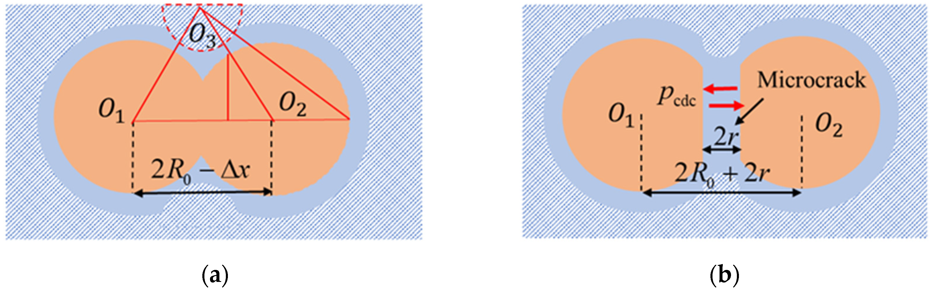
4.2. Micromechanical Analysis of Frozen Clay Pores

For saturated permafrost, its skeleton can be regarded as a network structure formed by capillaries of different diameters [21], and there is almost no closed space inside, and all pores are filled with water or ice. Any large clay pore was taken as the research object. To simplify the calculation model, the clay pore was regarded as a spherical cavity with radius R, the penetrating capillary channel was regarded as a uniform cylinder with radius r and the ice pressure ps in the pipeline was isotropic, as shown in Figure 3.
Ignoring the density difference between ice and water, the phase transition process of ice and water satisfies the Clausius–Clapeyron equation
p s p w = q m ρ s T m T f T m ,
where ps is the ice pressure, Pa; pw is the Darcy pressure caused by the pore water, Pa; qm is the latent heat of phase transition per unit mass (qm 3.35 × 10⁵ J/kg); ρs is the ice density (ρs 920 kg/m3). Therefore, in the process of freezing, the pressure exerted by ice crystals on the clay wall is proportional to the freezing temperature.
With the growth of ice crystals, the water in the pores is discharged from the pores, and the growth rate of the ice crystals is equal to the drainage rate of the pores. Therefore, it can be considered that the pressure inside the pores at the initial stage of freezing (that is, the first stage) is 0, and the external pressure is mainly borne by the clay skeleton. The ice pressure ps is equal to 0.
Ignoring the interface resistance, the Darcy pressure is equivalent to the external pressure [22]. The Equation (10) can be expressed as
p s = P + q m ρ s T m T f T m .
Then, the freezing temperature of the soil can be expressed as
T ic = T m T m ( P p s ) q m ρ s ,
When the ice pressure equals 0, the temperature corresponding to Ts is the nucleation temperature, that is, ice crystals can nucleate at any temperature less than or equal to Ts.
Considering the interaction of surface forces (that is, the second stage), based on the interface premelting theory, there is a repulsive force pcdw [23] between the ice and clay wall. In order to satisfy the local thermodynamic equilibrium, the pressure in the unfrozen water film is reduced to balance the repulsive force between the ice and the clay wall, resulting in the flow of water from the unfrozen soil to the pore ice. Therefore, the growth rate of pore ice in this stage is equal to the rate of water migration. The mechanical equilibrium relationship between the ice and clay wall can be expressed as
p s p w = σ sw K sw + p cdw ,
where σ sw is the ice/water interfacial tension ( σ sw 29 × 10−3 J/m2); pw is the pore water pressure, Pa; Ksw is the curvature, which is positive when the center of curvature is in the center of the clay; pcdw is the separation pressure between the ice and clay wall, Pa. Due to the separation pressure only being based on a small scale, pcdw at the pore tip is 0.
Based on the continuum theory, the pore water should be equal to the external pressure; then, the pressure exerted by ice crystals on the clay wall can be expressed as
p s = σ sw K sw + P ,
The angle between the ice crystal and the clay wall is assumed to be θ . The curvature of the ice/water interface at the ice cap can be expressed as
K sw = 2 cos θ r 0 .
When θ = 180°, the ice cap is a sphere of radius r0; when θ < 180°, the ice is in direct contact with the wall of the hole. Therefore, during freezing, when the ice crystals in the pores reach a critical value, frost heaving or ice cap formation occurs [24]. The relationship between the freezing temperature and ice cap radius r0 can be obtained by simultaneous Equations (11), (14) and (15):
r 0 = 2 σ sw q m ρ s T m T m T f .
As shown in Figure 3, the curvature of the ice/water interface at the ice cap can be obtained according to Equation (15), and the spherical end curvature of the ice cap is 2/r0. When the ice crystal enters the pore, the ice crystal exerts the maximum compressive stress on the pore wall [25]. In order to satisfy the local mechanical equilibrium relationship, the pore wall needs to provide additional stress pc equilibrium ice pressure ps. Then, pc can be expressed as
p c = 2 σ sw r 0 = q m ρ s T m T f T m .
Due to the surfaces of clay and ice crystals being hydrophilic, there is always an unfrozen water film on the wall of ice and clay [26]. Therefore, the capillary radius can be expressed as
r = r 0 + d = 2 σ sw q m ρ s T m T m T f + d
where d is the thickness of unfrozen water film on the ice and clay wall, and its value range is 0.2~50 nm [27]. For example, when the temperature is −1 °C, the thickness of the unfrozen water film between the pore ice and clay wall is about 10 nm [28]. When the freezing temperature is lower than −1 °C, ice crystals can invade the pores of any pore size r 78 nm, and when the temperature is lower than −30 °C, ice crystals can invade the pores of pore r  2.85 nm. Therefore, the frozen pores and unfrozen pores at different freezing temperatures can be distinguished according to the threshold (Equation (18)) at which the ice cap can invade the pore size. In addition, it can be obtained from Equation (17) that the freezing temperature is proportional to the pore size. The smaller the pore size is, the harder it is to freeze.

4.3. The Formation of Initial Cracks

Cracks are the result of the initiation, propagation and penetration of microcracks in the process of soil stress, and they are the macroscopic reaction of the accumulation of deformation and the failure of the soil microstructure [29]. From the above analysis, it can be seen that the appearance and growth of pore ice will reduce the water content in pores, which will lead to the local consolidation of soil in the frozen fringe and unfrozen area. In the second stage of ice crystal growth, the water content in pores is the lowest, and when the water content of the locally saturated soil reaches or is less than the value of the adsorbed bound water, there is only adsorbed water in the soil. The adsorbed water is subjected to the strong electrostatic attraction and hydrogen bonding of soil particles, and its properties are similar to those of solids. Therefore, the soil at the frozen fringe can be regarded as a linear elastic solid [30]. The further growth of the crystal will resist the bondage of the surrounding environment, which will eventually lead to the destruction of the pore structure and the local fracturing between soil particles to form microcracks. Based on the surface electrical properties of clay particles, the fracturing of the soil skeleton and the surface interaction forces pcdc between microcracks appear simultaneously, as shown in Figure 4. pcdc is a single-valued function of particle spacing h0. When pcdc(h0) is negative, this indicates that there is attraction between adjacent clay particles; when pcdc(h0) is positive, this indicates that there is repulsion between adjacent clay particles. Therefore, when pore ice infiltrates into soil cracks, the additional stress needs to be provided by the pore walls to meet the local mechanical equilibrium relationship and is expressed as
p ic = P p s p cdc ( h 0 ) ,
Based on hypothesis 1, it is known that the soil cracks formed by ice pressure are more than one and are multi-directional.
Taking adjacent clay particles with a radius of R0 as an example, Liu et al. [31], based on the uniform spherical matrix ideal model [32], by considering the interaction of particle surface forces and taking ice pressure as the destructive force of bond strength between soil particles, proposed that when ice pressure is greater than the separation pressure between clay particles pLsep, adjacent clay particles are separated, and the separation pressure expression between adjacent clay particles is given
p Lsep = P + K σ sw p cdc ( h 0 ) ,
where h0 is the distance between adjacent clay particles, nm; pcdc(h0) is the surface between charged clay plates with a spacing of h0.
Among them, the surface forces involved include van der Waals gravitation, electrostatic repulsion and structural forces. As shown in Figure 4, the effective contact surface dAss per unit area between adjacent clay particles can be expressed as π R 0 dx. Then, pcdc(h0) can be expressed as
p cdc ( h 0 ) = R [ A H 12 h 0 2 + 2 π ρ 0 2 z 2 exp ( k h 0 ) + π λ k 0 exp ( h 0 λ ) ] ,
where AH is the Hamaker constant (AH 10−19 J); k0 and λ are structural force coefficients (k0 1.5 × 10¹⁰ Pa, λ ≈ 0.05 nm).
When considering the shrinkage of the soil as the temperature decreases during the freezing process, as shown in Figure 4, the change in the distance between the centers of adjacent particles x1 caused by temperature changes can be expressed as
x 1 = 2 α R 0 ( T T 0 ) ,
where α is the linear thermal expansion coefficient of clay (α ≈ 5~6 × 10⁻⁶ °C−1), which is related to the bulk density, cation exchange capacity and specific surface area of clay particles [33]; T is the current temperature, K; T0 is the initial temperature, K. Therefore, when ice crystals infiltrate into cracks during freezing, the final displacement of adjacent clay particles should be the sum of the displacement x1 caused by thermal expansion and the displacement 2r0 caused by ice crystal growth. Due to the clay at the frozen fringe being regarded as a linear elastic solid in this study, h0 cannot be simply understood as the distance between adjacent clay particles, and the shrinkage of soil particles due to temperature reduction should also be considered, that is, h0 = 2r.
Combined with the above analysis, Equation (20) is briefly modified to obtain the separation pressure between particles when the linear elasticity of soil is considered
p sep = P p cdc ( 2 r ) ,
Therefore, when the following conditions are met, initial cracks will appear between the compacted clay particles:
p s p sep ,
Attention: ps is the ice pressure at the clay crack, Pa.

4.4. Crack Propagation

From the above analysis, it can be seen that the soil at the frozen fringe can be regarded as a linear elastic solid, so the theory of linear elastic fracture mechanics can be used to study crack propagation. First of all, based on the continuum mechanics theory, it is known that the properties of cracks formed by the fracturing of adjacent clay particles should be similar to pores [34]. Therefore, when r < r0, the cracks are filled with an aqueous solution; when r < r0, ice crystals can grow into the inside of the crack and continue to grow, which leads to the expansion of the crack. For the closed pores full of ice crystals, the existence of ice pressure promotes the fracturing of the soil skeleton, but the existence of external pressure P has the opposite effect. Therefore, based on the linear superposition principle, the effective stress in the closed pores can be expressed as
σ = p s P ,
where σ is the effective stress of the crack, Pa.
As we all know, the stress intensity factor KI is a physical quantity that reflects the strength of the elastic stress field at the crack tip and is a measure of the trend in crack propagation or the driving force of crack propagation, and it is related to the size of the crack, the geometric characteristics of the member and the size of the external load, which can be expressed as [35]
K I = σ π a f ( ξ ) ,
where a is the length of crack, nm; ξ is the spread of the crack, ξ = 2r/a; f ( ξ ) is the correction coefficient of the stress intensity factor, when ξ = 0, f ( ξ ) = 1. In order to correctly use the Clausius–Clapeyron equation, let a = λ 0 R 0 , where λ ≥ 10; in addition, we know that the crack length should be much larger than the crack width, that is, a > 2r. From our knowledge of linear elastic fracture mechanics, we also know that [36]: when KI > KIC, the cracks propagate instantly at a velocity close to the elastic compression wave, which eventually leads to the fracture of the soil skeleton, where KIC is the fracture toughness of the solid, Pa; when KIB < KI < KIC, the cracks will not propagate or will propagate slowly and steadily, where KIB is called the stress corrosion limit, Pa; when KI < KIB, the crack propagation stops. The range of KIB/KI is 0.3–0.4 [37].
In order to simplify the model, this study takes the value of ξ as 0. When KI = KIC, Equation (26) can be obtained by a brief transformation, and when the formation is established, the solid begins to break
σ = K IC π λ 0 R 0 σ t ,
where σ t is the ultimate tensile strength of solids, Pa.
When KIC = 0, σ = 0, there are no cracks of soil skeleton; when KIC > 0, σ > σ t , there are cracks in the soil structure at the freezing fringe, which expand with the infiltration of ice crystals and finally form a seepage path. Based on the research results of Rice et al. [38], the Vc expression of the fracture propagation velocity can be obtained as follows
V c = v exp [ b K I ( K I K IC 1 ) ] v exp [ b K I ( K * K IC 1 ) ] ,   K I > K * V c = 0 ,   K I K * } ,
where v and b are the material parameters independent of KI.

4.5. Mechanism of Ice Lens Formation

The functional relationship between the freezing temperature and ultimate tensile strength of soil can be obtained by simultaneously applying Equations (13) and (27)
σ t = K IC π λ 0 R 0 = ρ s q m ( T m T ic ) T m ,
That is, the ultimate tensile strength of the frozen edge soil is positively related to the freezing temperature. However, the ultimate tensile strength of the soil in the test process is related to the soil types, test environment, water content of test block and other factors, which is well explained by the research literature [39].
Therefore, it will first nucleate in the larger pores on the same isotherm and when the freezing temperature meets the pore ice nucleation temperature. In addition, based on the pore distribution characteristics of the soil structure, it can be known that the larger pores mentioned here are not the only pores. Based on the relationship between the ultimate tensile strength of soil and the freezing temperature, when the ice core grows to the whole pore, the crack first spreads along the horizontal direction under the action of ice pressure and forms an infiltration path for ice crystal growth, and finally forms a banded ice lens.
According to Akagawa’s [40] test case, when the average ultimate tensile strength of soil is 0.75 MPa, the freezing temperature is lower than −0.665 °C, and the new ice lens can be nucleated again. However, within Akagawa‘s experiment, the initial temperatures of the new ice lens are 0 °C, −0.4 °C,−0.6 °C and −0.8 °C. Obviously, 0 °C, −0.4 °C and −0.6 °C are not enough for ice lens nucleation. Therefore, the formation of new lenses should be the result of the longitudinal extension of the crack which induces the penetration of the old ice lens, rather than the result of repeated nucleation.
In conclusion, the extension of cracks is the main reason for the formation of periodic ice lenses. When the separation pressure psep between particles is greater than or equal to the pore ice pressure ps, the soil skeleton breaks. Pore ice grows parallel to the direction of fracture extension and promotes the further expansion of the fracture, eventually connecting the clay network structure into the permeable path of ice crystals, thus inducing most pores to freeze. Swainson’s test results [41] also confirm the correctness of this conclusion. Based on the hypothesis (1), we know that the development of cracks is multidimensional. Therefore, the lateral extension of the crack promoted the formation of the zonal lens, and the formation of the new ice lens should be caused by the growth of the old ice lens along the longitudinal crack. Repeat the above steps until the freezing process reaches the final required temperature, so that the one-dimensional frozen soil column forms a periodic banded ice lens, as shown in Figure 1a.

5. Model Verification and Discussion

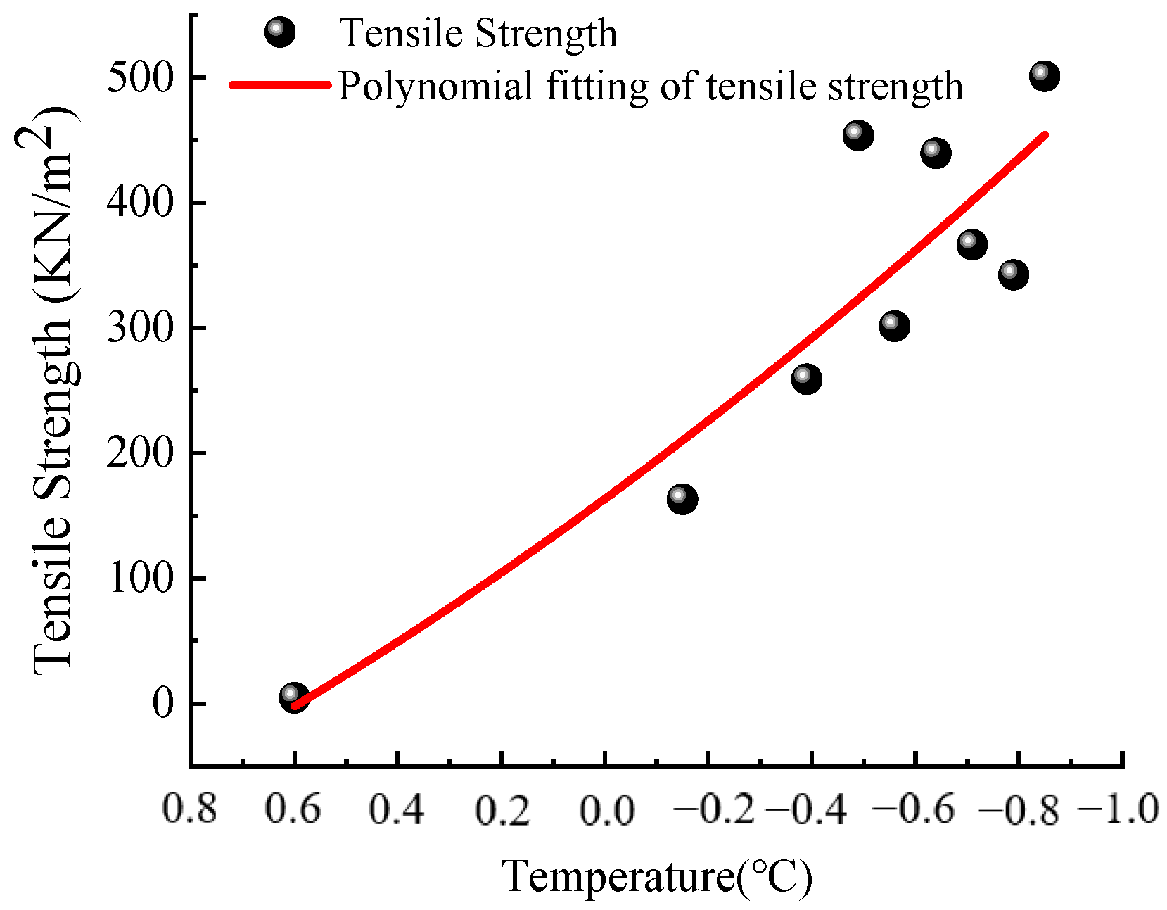
5.1. Model Validation

Akagawa et al. [40] carried out two open system freezing tests on Diluvial silt with an external pressure of 0.625 MPa and obtained that the average tensile strength of the soil was 0.75 MPa. Then, using the difference in the initial temperature of the ice lens in the two frost heave tests, and combined with the Clausius–Clapeyron equation, the average pore ice pressure was calculated to be 1.1 MPa. The test results show that it is reasonable to form a new ice lens when the ice pressure is greater than the sum of the ultimate tensile strength and the external pressure of the soil.
Then, Akagawa et al. [42] took frozen remolded Diluvial silt as the research object, and used the self-developed tensile test device to carry out several tensile tests of frozen soil in the temperature range of +0.6~1.31 °C. The relationship between the freezing temperature and soil tensile strength is shown in Figure 5, where the test strain rate is 2.31 mm/min.
−0.2 −0.4 −0.6 −0.8 −1.0 0.8 0.6 0.4 0.2 0.0
The relationship between the ultimate tensile strength of soil in the frozen fringe and the freezing temperature obtained from the calculation results of this study, Akagawa’s [42] test and Zhu’s [43] theoretical model is shown in Table 3.
It can be learned from Table 3 that the ultimate tensile strength of soil calculated in this study is consistent with the existing experimental and theoretical values, that is, the ultimate tensile strength of soil increases with the decrease in the freezing temperature. It can be seen from error analysis that the ultimate tensile strength of soil mass calculated in this study is closer to the test value than that calculated by Zhu’s theoretical model.

5.2. Discussion

In combination with Equations (23), (24) and (27), we can obtain
p sep = σ t .
This means that the tensile strength of soil at the macroscopic scale is in good agreement with the intergranular separation pressure at the molecular scale in judging the initial conditions of new ice lenses. Starting from the molecular scale, considering the surface charge effect of clay particles, the surface force caused by the weak overlap of the charged solid surface diffusion double layer was applied to the growth process of single pore ice. It can well describe the micromechanical characteristics of the pore structure involved in each stage of ice crystal growth. However, the ice lens in the one-dimensional freezing process is not a single one; instead, it is a macroscopic ice layer that alternates with the soil in the direction perpendicular to the temperature gradient. Therefore, in the process of studying the formation mechanism of ice lenses, besides the growth of single pore ice crystals, the formation of new lenses should be considered.
Based on the contents of Section 4.3 and Section 4.4, when the ice pressure is greater than the separation pressure between adjacent clay particles, microcracks appear in the soil, which can continue to expand with the increase in the ice pressure. In general, in order to reasonably apply the Clausius–Clapeyron equation, suppose that the expansion of the crack ξ is greater than 10R0, and the distance between particles is much larger than the range of action that can cause the surface charge of charged solids. The introduction of the knowledge on crack propagation in linear elastic fracture mechanics just makes up for this deficiency. Equation (30) proves the rationality of this idea. Based on the analysis of the pore structure of saturated clay in Section 4.1, it is known that only when the continuous expansion of pore ice squeezes the surrounding clay wall, which leads to the local consolidation of the frozen fringe and unfrozen soil, and when the soil with local consolidation contains only adsorbed water, the properties of the soil are similar to those of solids, which can meet the application conditions of linear elastic fracture mechanics. The idea of combining colloidal interface mechanics with linear elastic fracture mechanics was adopted in this study, which can not only describe the deformation and fracturing of clay skeletons caused by ice crystal growth in the freezing process in detail, but also give a reasonable explanation for the formation mechanism of the new lens, thus demonstrating the rationality of this research.

6. Conclusions

In this study, a theoretical model of the ice crystals growth process considering the surface charge is proposed by combining linear elastic fracture mechanics with colloidal interface mechanics. The theoretical model takes the growth of old ice lenses and the formation standard of new ice lenses as the main line and gradually discusses the deformation and fracturing of clay skeletons caused by ice crystal growth during freezing. The main conclusions are as follows:
  • An ice lens growth model of saturated clay considering the effect of the surface charge is proposed. That is, the ice lens growth process of frozen saturated clay is as follows: the ice nucleus on the clay surface is born, the ice crystals grow in the pores and the ice crystal pressure causes the cracks to extend to the adjacent pores, resulting in a new ice lens. The formulas for calculating the pressure on the clay wall under the action of ice crystals in clay pores when ice crystals are formed and filled with cracks were given.
  • The appearance and growth of pore ice in frozen soil reduces its moisture content. When there is only adsorbed water in the soil, the frozen edge soil can be regarded as a linear elastic solid, and the ultimate tensile strength of the soil is taken as the criterion for soil skeleton fracturing. It is proved that there is a good consistency between the soil tensile strength of the macroscopic dimension and the intergranular separation pressure of the molecular dimension in judging the production conditions of the new lens.
  • The conditions for the initial crack and propagation of frozen clay are as follows: when KIC = 0, σ = 0, there are no cracks of soil skeleton; when KIC > 0, σ     σ t , there are cracks in the soil structure at the freezing fringe, which expand with the infiltration of ice crystals.
  • The expansion of soil cracks at the frozen fringe is the main cause of frost heaving. Only when the initial cracks of the soil under the action of ice pressure make the clay skeleton form a permeable path can the pores with more pore sizes be frozen. The lateral extension of cracks promotes the formation of zonal lenses, and the formation of new lenses should be the result of the growth of old lenses along vertical cracks rather than secondary nucleation.

Author Contributions

Conceptualization, X.L. and H.C. (Hua Cheng); methodology, X.L. and H.C. (Hanqing Chen); validation, H.C. (Hua Cheng) and X.L.; formal analysis, L.G. and X.W.; investigation, X.L. and X.W.; resources, L.G.; data curation, X.L. and H.C. (Hanqing Chen); writing—original draft preparation, X.L.; writing—review and editing, H.C. (Hua Cheng) and H.C. (Hanqing Chen); project administration, X.L.; funding acquisition, X.L. and H.C. (Hua Cheng). All authors have read and agreed to the published version of the manuscript.

Funding

This research was funded by the National Natural Science Foundation of China (No.51874005), Major Science and Technology Projects in Anhui Province (202003c08020007) and the Anhui University Scientific Research Project (YJS20210386).

Institutional Review Board Statement

Not applicable.

Informed Consent Statement

Not applicable.

Data Availability Statement

Not applicable.

Acknowledgments

The authors extend their appreciation to the National Natural Science Foundation of China (No. 51874005), Major Science and Technology Projects in Anhui Province (202003c08020007) and the Anhui University Scientific Research Project (YJS20210386).

Conflicts of Interest

The authors declare no conflict of interest.

References

  1. Meyer, C.R.; Fernandes, M.C.; Creyts, T.T.; Rice, J.R. Effects of ice deformation on Röthlisberger channels and implications for transitions in subglacial hydrology. J. Glaciol. 2016, 62, 750–762. [Google Scholar] [CrossRef]
  2. Taber, S. The mechanics of frost heaving. J. Geol. 1930, 38, 303–317. [Google Scholar] [CrossRef]
  3. O’Neill, K.; Miller, R.D. Exploration of a rigid ice model of frost heave. Water Resour. Res. 1985, 21, 281–296. [Google Scholar] [CrossRef]
  4. Ishizaki, T.; Yoneyama, K.; Nishio, N. X-ray technique for observation of ice lens growth in partially frozen, saturated soil. Cold Reg. Sci. Technol. 1985, 11, 213–221. [Google Scholar] [CrossRef]
  5. Watanabe, K.; Mizoguchi, M. Ice configuration near a growing ice lens in a freezing porous medium consisting of micro glass particles. J. Cryst. Growth. 2000, 213, 135–140. [Google Scholar] [CrossRef]
  6. Azmatch, T.F.; Sego, D.C.; Arenson, L.U.; Biggar, K.W. New ice lens initiation condition for frost heave in fine-grained soils. Cold Reg. Sci. Technol. 2012, 82, 8–13. [Google Scholar] [CrossRef]
  7. Watanabe, K. Relationship between growth rate and supercooling in the formation of ice lenses in a glass powder. J. Cryst. Growth. 2002, 237, 2194–2198. [Google Scholar] [CrossRef]
  8. Martin, R.T. Rhythmic Ice Banding in Soil; Highway Research Board Bulletin: Washington, DC, USA, 1959; pp. 11–23. [Google Scholar]
  9. Konrad, J.M.; Morgenstern, N.R. A mechanistic theory of ice lens formation in fine-grained soils. Can. Geotech. J. 1980, 17, 473–486. [Google Scholar] [CrossRef]
  10. You, J.X.; Wang, J.C.; Wang, L.L.; Wang, Z.J.; Li, J.J.; Lin, X. Can secondary nucleation exist in ice banding of freezing colloidal suspensions? Chin. Phys. B 2016, 25, 128202. [Google Scholar] [CrossRef] [Green Version]
  11. Israelachvili, J.N. Intermolecular and Surface Forces, 3rd ed.; Academic Press: New York, NY, USA, 2010; pp. 190–195. [Google Scholar]
  12. Saarenketo, T. Electrical properties of water in clay and silty soils. J. Appl. Geophys. 1998, 40, 73–88. [Google Scholar] [CrossRef]
  13. Ma, W. Water-Solid Interface Chemistry and Adsorption Technology, 1st ed.; Metallurgical Industry Press: Beijing, China, 2011; pp. 92–95. ISBN 9787502457174. [Google Scholar]
  14. Yu, F.; Guo, P.; Lai, Y.M.; Stolle, D. Frost heave and thaw consolidation modelling. Part 1: A water flux function for frost heaving. Can. Geotech. J. 2020, 57, 1581–1594. [Google Scholar] [CrossRef]
  15. Ji, Y.K.; Zhou, G.Q.; Zhou, Y.; Vandeginste, V. Frost heave in freezing soils: A quasi-static model for ice lens growth. Cold Reg. Sci. Technol. 2019, 158, 10–17. [Google Scholar] [CrossRef]
  16. Saruya, T.; Kurita, K.; Rempel A., W. Experimental constraints on the kinetics of ice lens initiation and growth. Phys. Rev. E 2013, 87, 032404. [Google Scholar] [CrossRef]
  17. Cheng, H.; Chen, H.Q.; Cao, G.Y.; Rong, C.X.; Yao, Z.S.; Cai, H.B. Migration mechanism of capillary-film water in frozen soil and its experimental verification. Chin. J. Geotech. Eng. 2020, 42, 1790–1799. [Google Scholar]
  18. Dobson, M.C.; Ulaby, F.T.; Hallikainen, M.T.; El-rayes, M.A. Microwave dielectric behavior of wet soil-Part II: Dielectric mixing models. IEEE. T. Geosci. Remote 1985, 23, 35–46. [Google Scholar] [CrossRef]
  19. Jin, X.; Yang, W.; Meng, X.H.; Lei, L.L. Deduction and application of unfrozen water content in soil based on electrical double-layer theory. Rock Soil Mech. 2019, 40, 1449–1456. [Google Scholar] [CrossRef]
  20. Gonçalvès, J.; Rousseau-Gueutin, P.; De Marsily, G.; Cosenza, P.; Violette, S. What is the significance of pore pressure in a saturated shale layer? Water Resour. Res. 2010, 46, W04514. [Google Scholar] [CrossRef]
  21. Kong, B.W.; Ding, Z.; He, S.H.; Zhuang, J.H. Experimental study on pore features and dynamic behaviors of soft clay under different confine pressures during freezing. Chin. J. Rock Mech. Eng. 2020, 39, 2328–2340. [Google Scholar] [CrossRef]
  22. Style, R.W.; Peppin, S.S.L. The kinetics of ice-lens growth in porous media. J. Fluid. Mech. 2012, 692, 482–498. [Google Scholar] [CrossRef] [Green Version]
  23. Maeno, N.; Nishimura, H. The electrical properties of ice surfaces. J. Glaciol. 1978, 21, 193–205. [Google Scholar] [CrossRef] [Green Version]
  24. Everett, D.H. The thermodynamics of frost damage to porous solids. Trans. Faraday Soc. 1961, 57, 1541–1551. [Google Scholar] [CrossRef]
  25. Scherer, G.W. Stress from crystallization of salt. Cement. Concr. Res. 2004, 34, 1613–1624. [Google Scholar] [CrossRef]
  26. Takagi, S. The adsorption force theory of frost heaving. Cold Reg. Sci. Technol. 1980, 3, 57–81. [Google Scholar] [CrossRef]
  27. Rosenberg, R. Why is ice slippery? Phys. Today 2005, 58, 50–55. [Google Scholar] [CrossRef] [Green Version]
  28. Furukawa, Y.; Ishikawa, I. Direct evidence for melting transition at interface between ice crystal and glass substrate. J. Cryst.Growth 1993, 128, 1137–1142. [Google Scholar] [CrossRef]
  29. Fang, Y.; Yao, Z.S.; Li, X.W.; Xu, Y.J.; Huang, X.W. Durability of reactive powder concrete of drilling shaft and triaxial compression damage constitutive model under composite salt erosion. J. Build. Eng. 2022, 62, 105395. [Google Scholar] [CrossRef]
  30. Graham, J.; Houlsby, G.T. Anisotropic elasticity of a natural clay. Géotechnique 1983, 33, 165–180. [Google Scholar] [CrossRef]
  31. Liu, X.Y.; Cheng, H.; Chen, H.Q.; Guo, L.H.; Fang, Y.; Wang, X.S. Theoretical Study on Freezing Separation Pressure of Clay Particles with Surface Charge Action. Crystals 2022, 12, 1304. [Google Scholar] [CrossRef]
  32. Gilpin, R.R. A model for the prediction of ice lensing and frost heave in soils. Water Resour. Res. 1980, 16, 918–930. [Google Scholar] [CrossRef]
  33. Gray, C.W.; Allbrook, R. Relationships between shrinkage indices and soil properties in some New Zealand soils. Geoderma 2002, 108, 287–299. [Google Scholar] [CrossRef]
  34. Murton, J.B.; Peterson, R.; Ozouf, J.C. Bedrock fracture by ice segregation in cold regions. Science 2006, 314, 1127–1129. [Google Scholar] [CrossRef] [PubMed]
  35. Xue, S.F.; Hou, M.S. Engineering Fracture Mechanics; China University of Petroleum Press: Shandong, China, 2006; pp. 10–20. [Google Scholar]
  36. Atkinson, B.K.; Rawlings, R.D. Acoustic emission during stress corrosion cracking in rocks. Earthq. Predict. Int. Rev. 1981, 4, 605–616. [Google Scholar] [CrossRef]
  37. Segall, P. Rate-dependent extensional deformation resulting from crack growth in rock. J. Geophys. Res.-Solid Earth 1984, 89, 4185–4195. [Google Scholar] [CrossRef]
  38. Rice, J.R. Thermodynamics of the quasi-static growth of Griffith cracks. J. Mech. Phys. Solids 1978, 26, 61–78. [Google Scholar] [CrossRef] [Green Version]
  39. Azmatch, T.F.; Sego, D.C.; Arenson, L.U.; Biggar, K.W. Tensile strength and stress–strain behaviour of Devon silt under frozen fringe conditions. Cold Reg. Sci. Technol. 2011, 68, 85–90. [Google Scholar] [CrossRef]
  40. Akagawa, S.; Satoh, M.; Kanie, S.; Mikami, T. Effect of tensile strength on ice lens initiation temperature. In Proceedings of the 13th International Conference on Cold Regions Engineering: Current Practices in Cold Regions Engineering, Orono, ME, USA, 23–26 July 2006; pp. 1–12. [Google Scholar] [CrossRef]
  41. Swainson, I.P.; Schulson, E.M. Invasion of ice through rigid anisotropic porous media. J. Geophys. Res.-Solid Earth 2004, 109, B12205. [Google Scholar] [CrossRef]
  42. Akagawa, S.; Nishisato, K. Tensile strength of frozen soil in the temperature range of the frozen fringe. Cold Reg. Sci. Technol. 2009, 57, 13–22. [Google Scholar] [CrossRef]
  43. Zhu, Y.L.; Carbee, D.L. Tensile strength of frozen silt. J. Glaciol. Geocryol. 1986, 15–28. [Google Scholar]
Figure 1. Schematic diagram of the diffusion layer structure on the clay surface.
Crystals 12 01743 g001
Figure 2. Distribution and growth process model of saturated clay ice lens. (a) showing ice lenses that developed in a one-dimensional freezing experiment performed by Taber. The picture adapted with permission from ref. [2]. 1930, Taber. More details on “Copyright and Licensing” are available via the following link: https://doi.org/10.1086/623720; (b) is a schematic diagram of the growth of one-dimensional frozen soil ice lens; (c) is the model of the growth process of saturated clay ice lens. Where: P is the external pressure; Tc is the freezing temperature at the cold end; Tw is the freezing temperature at the warm end; Ts is the temperature of the warm end of the active ice lens; Tf is the freezing temperature; Tm is an absolute temperature; zs, zf and z = 0 are the corresponding position of Ts, Tf and Tw, respectively.
Crystals 12 01743 g002
Figure 3. Schematic diagram of the pore mechanics equilibrium of frozen clay.
Crystals 12 01743 g003
Figure 4. Schematic diagram of the initial microcrack due to freezing. Where (a) represents the geometric relationship between adjacent clay particles before micro-cracks occur; (b) represents the geometric relationship between adjacent clay particles after micro-cracks.
Crystals 12 01743 g004
Figure 5. The relationship between the tensile strength of the soil in the frozen fringe and the freezing temperature.
Crystals 12 01743 g005
Table 1. Pore distribution of soil samples before and after freezing and thawing.
D (nm)<33~100>100
Dbef (%)96.912.850.24
Dmel (%)95.444.090.47
Annotation: D is the pore diameter, nm; Dbef is the pore distribution before freezing, %; Dmel is the pore distribution after melting, %.
Table 2. The measured data of five soil elements.
Soil TypeSandy Soil/%Silt/%Clay/% ρ 0 / ( C / m 3 ) n0 (mol/m3)1/(k/m) × 10−9
Sandy loam51.5135.0613.430.1525.353.99
loam41.9649.518.530.1503.964.63
Silty loam 130.6355.8913.480.1665.403.97
Silty loam 217.1663.8419.000.1665.773.84
Silty clay5.0247.0647.380.1334.964.26
Annotation: Due to the thickness of the electric double layer being less sensitive to T, the calculated values in the table can represent the value of the parameter k−1 in the range of 0~25 °C.
Table 3. Relationship between the tensile strength of soil in the frozen fringe and freezing temperature.
Freezing Temperature (°C)−0.15−0.39−0.49−0.64−0.79−0.85
A1 (kPa)164417453439459499
Z1 (kPa)536741800876941965
Cal (kPa)169440552722891959
Er1 (%)35.521.864.594.192.2
Er2 (%)226.877.776.699.510593.4
Annotation: A1 is the test values of ultimate tensile strength of soil obtained from Akagawa’s test; Z1 is the calculated values of ultimate tensile strength of soil obtained from Zhu’s theoretical; Cal is the calculated values of ultimate tensile strength of soil obtained from this study; Er1 = |(Cal − A1)/A1| × 100%; Er2 = |(A1 − Z1)/A1| × 100%.
Publisher’s Note: MDPI stays neutral with regard to jurisdictional claims in published maps and institutional affiliations.

