
Cumulative Damage in Very High/Low Cycle Combined Fatigue for TC21 Titanium Alloy


Abstract
1. Introduction
2. Experimental Procedures
2.1. Materials
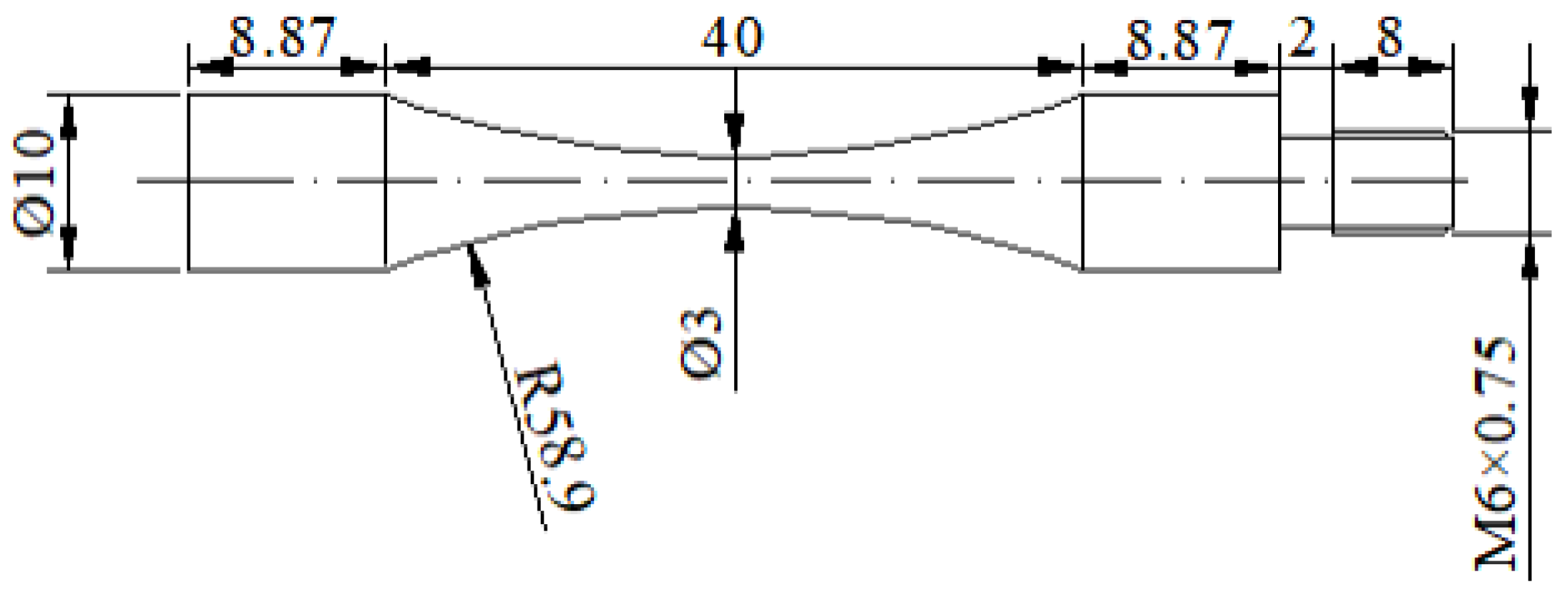
2.2. VHCF/LCF Combined Fatigue Tests
3. Results and Discussion
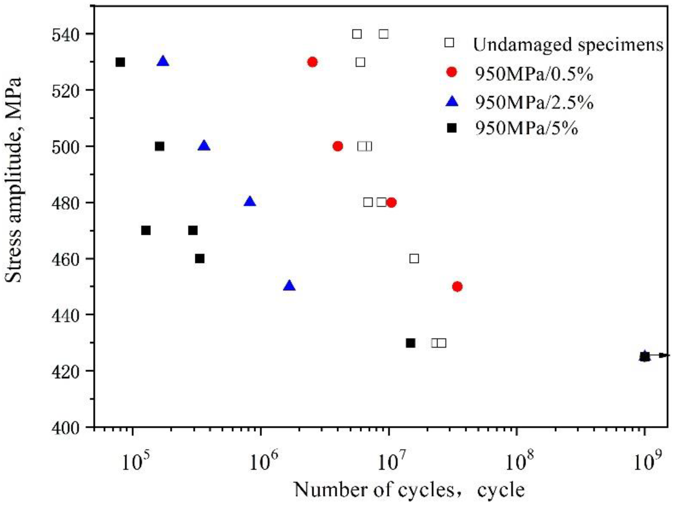
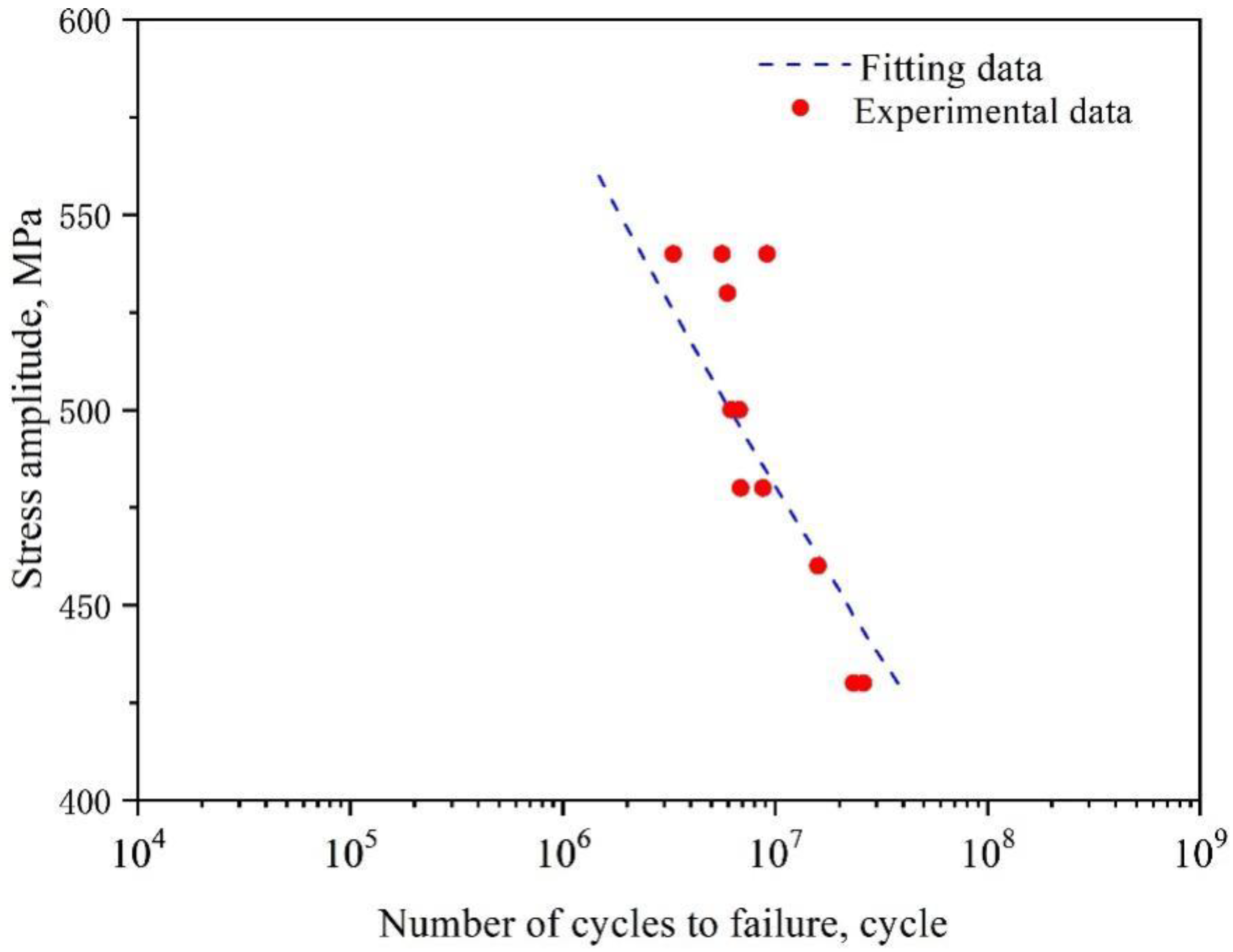
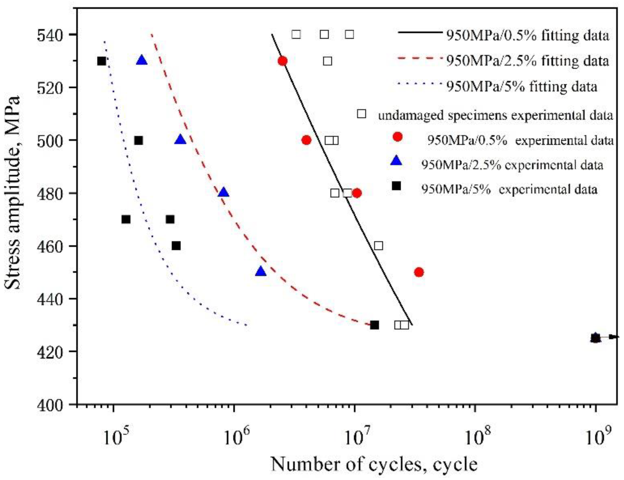
3.1. Effect of LCF Predamage on S-N Curves
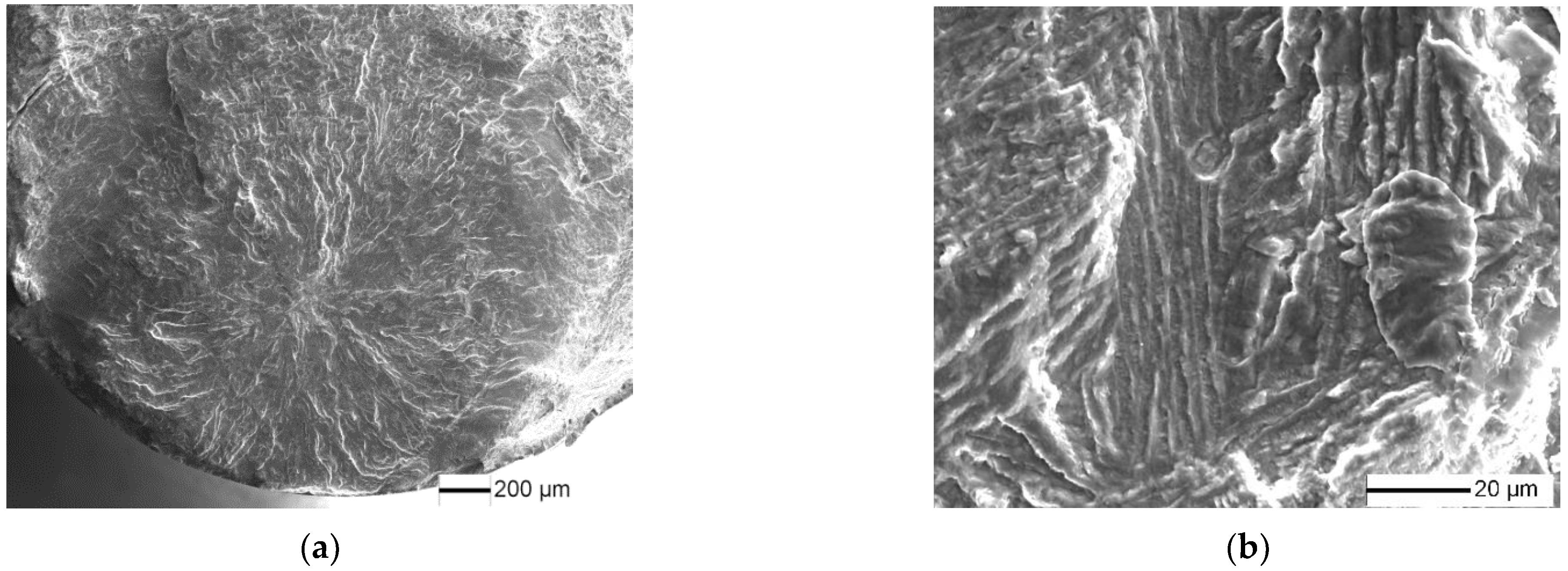
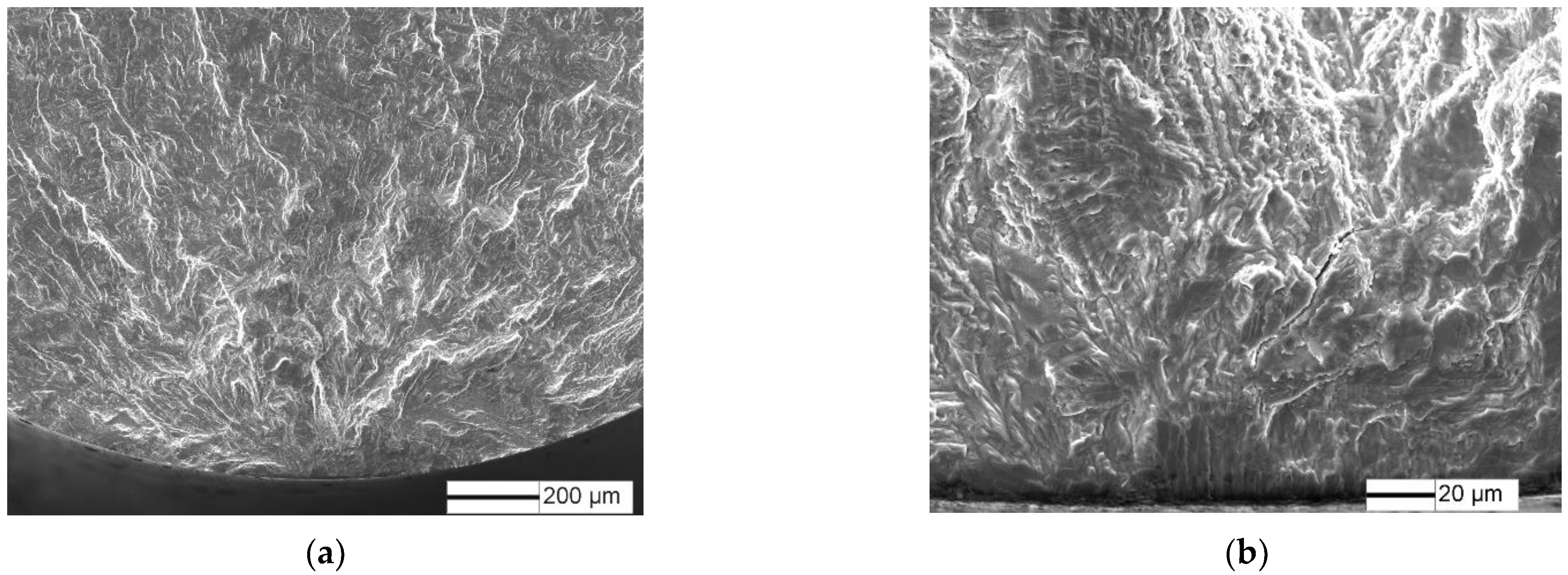
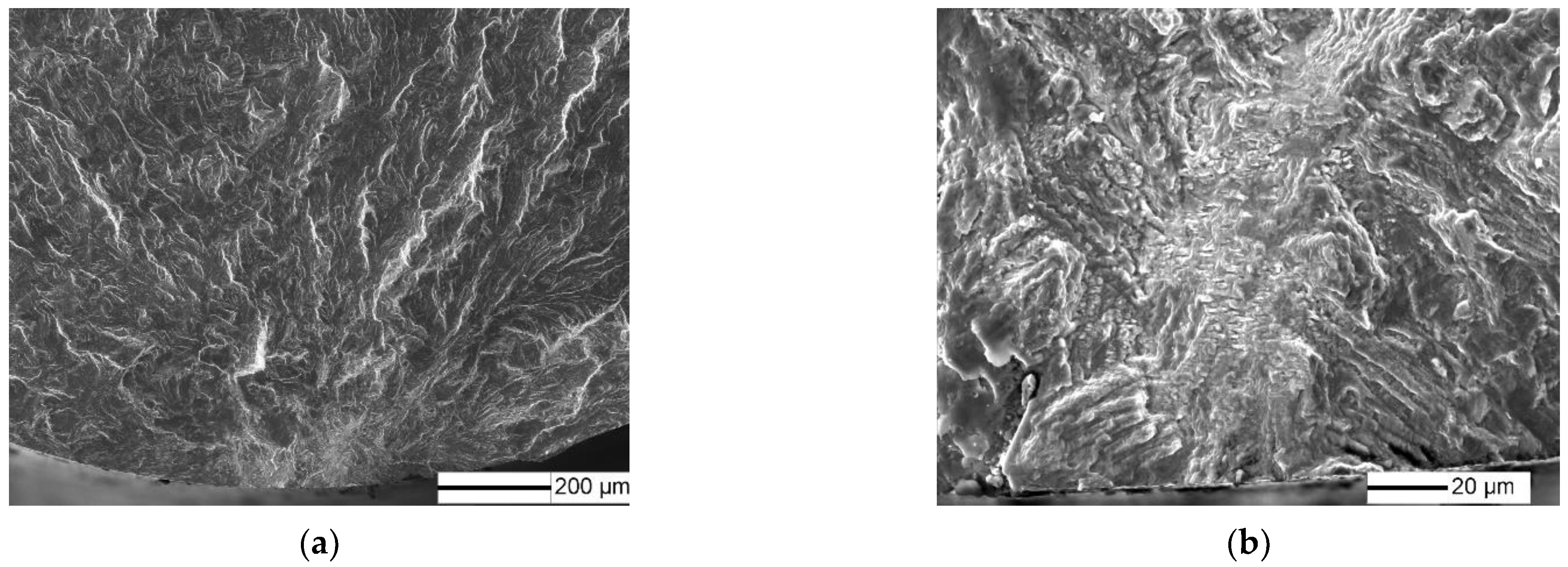
3.2. Fracture Analysis
3.3. Very High/Low Cycle Combined Fatigue Damage and Life Prediction
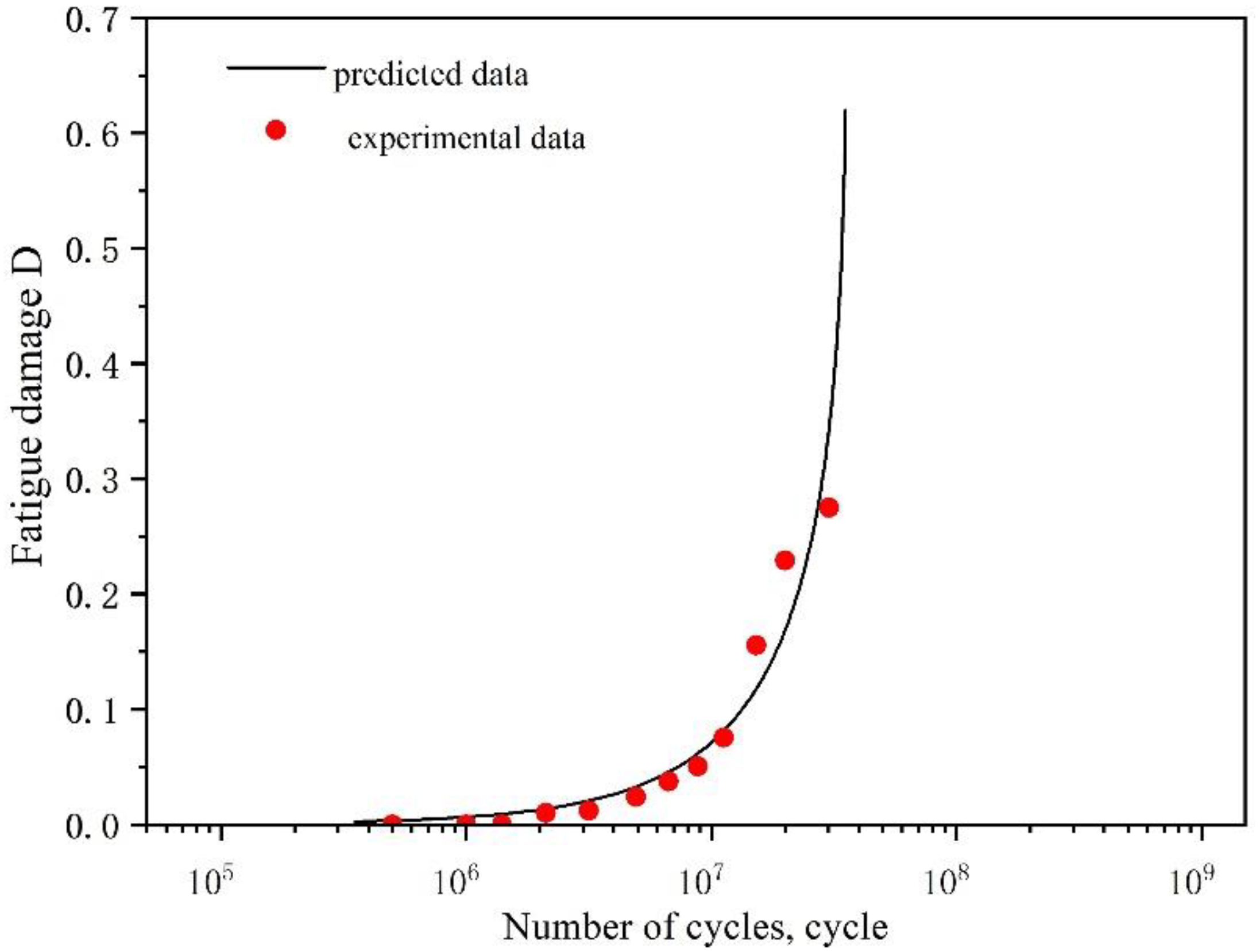
3.3.1. VHCF Damage Model
3.3.2. Prediction Model of Very High/Low Cycle Combined Fatigue
3.3.3. Prediction of Very High/Low Cycle Combined Fatigue Life
4. Conclusions
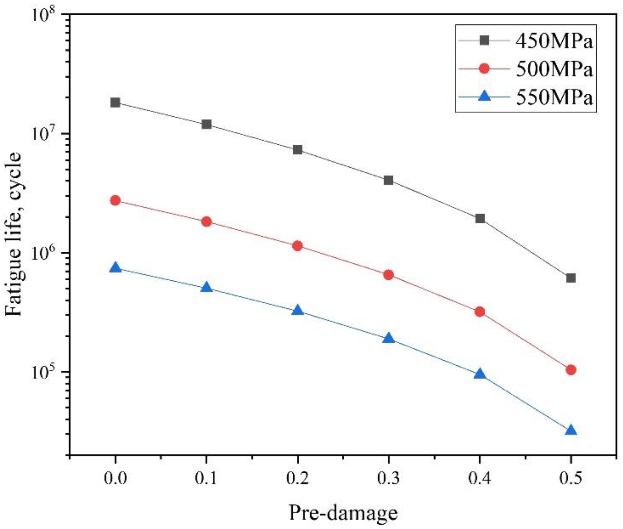
- LCF predamage with less than 5% of fatigue life had little influence on fatigue limit of TC21 titanium alloy, but reduced fatigue life. Fatigue cracks initiated on the surface of the specimen at high stress amplitude, while fatigue cracks initiated on the subsurface of the specimens at low stress amplitude, and crack initiation site presented the bright particle characteristics.
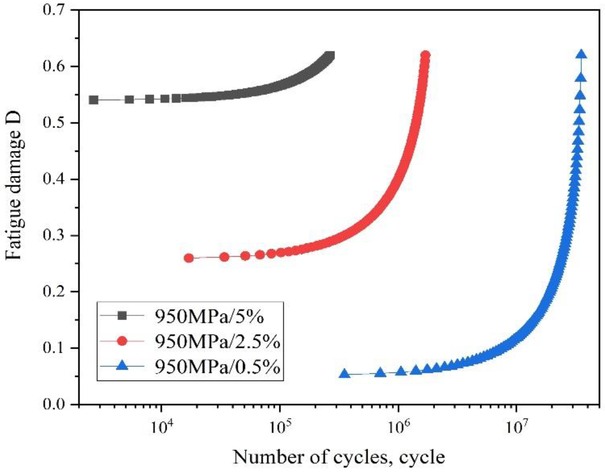
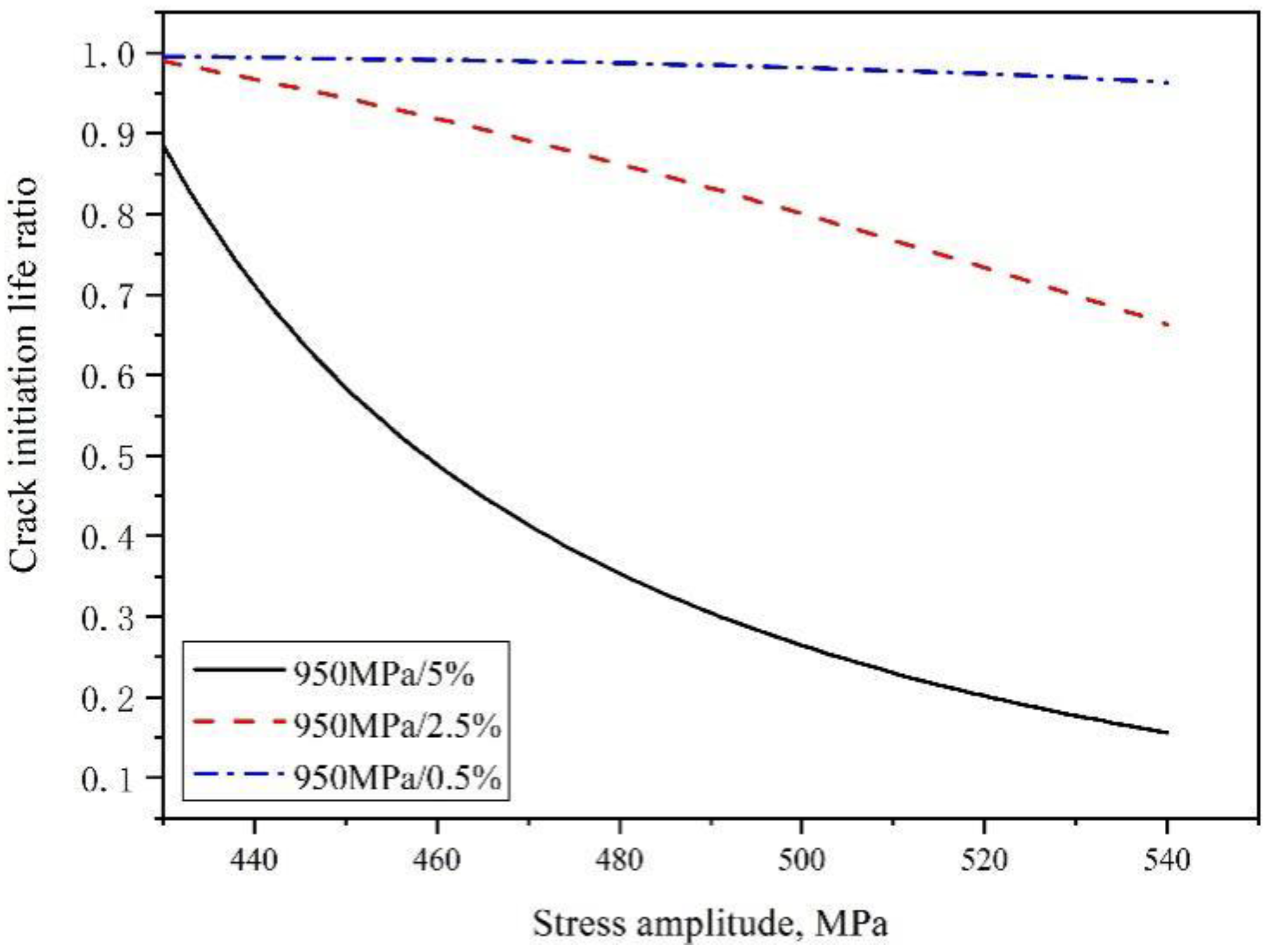
- Based on Lemaitre damage theory, a very high/low cycle combined fatigue damage model was established to analyze the fatigue damage process, which was consistent with the experimental data. The 5% LCF pre-damage value was the equivalent damage value which was close to the critical value of VHCF crack initiation. Fatigue crack initiation of the specimens with LCF predamage less than 5% took up the major components.
Author Contributions
Funding
Data Availability Statement
Conflicts of Interest
References
- Zhao, Q.; Sun, Q.; Xin, S.; Chen, Y.; Wu, C.; Wang, H.; Xu, J.; Wan, M.; Zeng, W.; Zhao, Y. High-strength titanium alloys for aerospace engineering applications: A review on melting-forging process. Mater. Sci. Eng. A 2022, 845, 143260. [Google Scholar] [CrossRef]
- Gao, T.; Xue, H.; Sun, Z.; Retraint, D.; He, Y. Micromechanisms of crack initiation of a Ti-8Al-1Mo-1V alloy in the very high cycle fatigue regime. Int. J. Fatigue 2021, 150, 106314. [Google Scholar] [CrossRef]
- Gao, T.; Xue, H.; Sun, Z.; Retraint, D. Investigation of crack initiation mechanism of a precipitation hardened TC11 titanium alloy at very high cycle fatigue loading. Mater. Sci. Eng. A 2020, 776, 138989. [Google Scholar] [CrossRef]
- Liu, F.; Peng, H.; Liu, Y.; Wang, C.; Wang, Q.; Chen, Y. Crack initiation mechanism of titanium alloy in very high cycle fatigue regime at 400 °C considering stress ratio effect. Int. J. Fatigue 2022, 163, 107012. [Google Scholar] [CrossRef]
- Li, C.; Li, W.; Cai, L.; Zhang, Y.; Sun, R.; Li, X.; Wang, P. Microstructure based cracking behavior and life assessment of titanium alloy at very-high-cycle fatigue with elevated temperatures. Int. J. Fatigue 2022, 161, 106914. [Google Scholar] [CrossRef]
- Liu, F.; Chen, Y.; He, C.; Li, L.; Wang, C.; Li, H.; Liu, Y. Tensile and very high cycle fatigue behaviors of a compressor blade titanium alloy at room and high temperatures. Mater. Sci. Eng. A 2021, 811, 141049. [Google Scholar] [CrossRef]
- Huang, Z.Y.; Wanger, D.; Bathias, C.; Chaboche, J.L. Cumulative fatigue damage in low cycle fatigue and gigacycle fatigue for low carbon-manganese steel. Int. J. Fatigue 2011, 33, 115–123. [Google Scholar] [CrossRef]
- Huang, Z.Y.; Wang, Q.Y.; Wagner, D.; Bathias, C. Effect of low cycle fatigue predamage on very high cycle fatigue. Theor. Appl. Mech. Lett. 2012, 2, 031007. [Google Scholar] [CrossRef]
- Nie, B.; Zhao, Z.; Ouyang, Y.; Chen, D.; Chen, H.; Sun, H.; Liu, S. Effect of low cycle fatigue predamage on very high cycle fatigue behavior of TC21 titanium alloy. Materials 2017, 10, 1384. [Google Scholar] [CrossRef]
- Pavlou, D. The theory of the S-N fatigue damage envelope: Generalization of linear, double-linear, and non-linear fatigue damage models. Int. J. Fatigue 2018, 110, 204–214. [Google Scholar] [CrossRef]
- Qiu, S.; Cui, H.; Zhang, H.; Wen, W.; Guo, J. A dual-threshold modelling approach for fatigue life prediction at combined high and low cycle fatigue. Int. J. Fatigue 2022, 164, 107110. [Google Scholar] [CrossRef]
- Yue, P.; Ma, J.; Huang, H.; Shi, Y.; Zu, J. Threshold damage-based fatigue life prediction of turbine blades at combined high and low cycle fatigue. Int. J. Fatigue 2021, 150, 106323. [Google Scholar] [CrossRef]
- Zhao, Z.; Wang, L.; Liu, L.; Chen, W. Prediction of combined cycle fatigue life of TC11 alloy based on modified nonlinear cumulative damage model. Chin. J. Aeronaut. 2021, 34, 73–84. [Google Scholar] [CrossRef]
- Schweizer, C.; Seifert, T.; Nieweg, B.; Von Hartrott, P.; Riedel, H. Mechanisms and modelling of fatigue crack growth at combined low and high cycle fatigue loading. Int. J. Fatigue 2011, 33, 194–202. [Google Scholar] [CrossRef]
- Morrissey, R.J.; Golden, P.; Nicholas, T. The Effect of Stress Transients on the HCF Endurance Limit in Ti-6Al-4V. Int. J. Fatigue 2003, 25, 1125–1133. [Google Scholar] [CrossRef]
- Hu, D.; Yang, Q.; Liu, H.; Mao, J.; Meng, F.; Wang, Y.; Wang, R. Crack closure effect and crack growth behavior in GH2036 superalloy plates at combined high and low cycle fatigue. Int. J. Fatigue 2017, 95, 90–103. [Google Scholar] [CrossRef]
- Li, X.; Song, L.; Bai, G. Deep learning regression-based stratified probabilistic combined cycle fatigue damage evaluation for turbine bladed disks. Int. J. Fatigue 2022, 159, 106812. [Google Scholar] [CrossRef]
- Bai, S.; Li, Y.; Huang, H.; Ma, Q.; Lu, N. A probabilistic combined high and low cycle fatigue life prediction framework for the turbine shaft with random geometric parameters. Int. J. Fatigue 2022, 165, 107218. [Google Scholar] [CrossRef]
- Gao, H.; Zio, E.; Wang, A.; Bai, G.; Fei, C. Probabilistic-based combined high and low cycle fatigue assessment for turbine blades using a substructure-based kriging surrogate model. Aerosp. Sci. Technol. 2020, 104, 105957. [Google Scholar] [CrossRef]
- Li, G.; Ke, L.; Ren, X.; Sun, C. High cycle and very high cycle fatigue of TC17 titanium alloy: Stress ratio effect and fatigue strength modeling. Int. J. Fatigue 2023, 166, 107299. [Google Scholar] [CrossRef]
- Liu, X.; Wang, X.; Liu, Z.; Chen, Z.; Sun, Q. Continuum damage mechanics based probabilistic fatigue life prediction for metallic material. J. Mater. Res. Technol. 2022, 18, 75–84. [Google Scholar] [CrossRef]
- Lemaitre, J.; Sermage, J.; Desmorat, R. A two scale damage concept applied to fatigue. Int. J. Fract. 1999, 97, 67–81. [Google Scholar] [CrossRef]
- Nie, B.; Liu, S.; Huang, X.; Qi, H.; Shi, B.; Zhao, Z.; Chen, D. Low cycle fatigue crack damage behavior of TC21 titanium alloy with basketweave microstructure. Crystals 2022, 12, 1211. [Google Scholar] [CrossRef]
- Nie, B.; Song, Y.; Huang, X.; Qi, H.; Zhao, Z.; Chen, D. Low Cycle fatigue behavior of TC21 titanium alloy with bi-Lamellar basketweave microstructure. Crystals 2022, 12, 796. [Google Scholar] [CrossRef]
- Bathias, C. Piezoelectric fatigue testing machines and devices. Int. J. Fatigue 2006, 28, 1438–1445. [Google Scholar] [CrossRef]
- Ren, W.; Nicholas, T. Effects and mechanisms of low cycle fatigue and plastic deformation on subsequent high cycle fatigue limit in nickel-base superalloy Udimet 720. Mater. Sci. Eng. A 2002, 332, 236–248. [Google Scholar] [CrossRef]
- Lemaitre, J.; Desmorat, R. Engineering Damage Mechanics: Ductile, Creep, Fatigue and Brittle Failures; Springer: Dordrecht, The Netherlands, 2006. [Google Scholar]
- Krewerth, D.; Lippmann, T.; Biermann, H. Influence of non-metallic inclusions on fatigue life in the very high cycle fatigue regime. Int. J. Fatigue 2016, 84, 40–52. [Google Scholar] [CrossRef]


Publisher’s Note: MDPI stays neutral with regard to jurisdictional claims in published maps and institutional affiliations. |
© 2022 by the authors. Licensee MDPI, Basel, Switzerland. This article is an open access article distributed under the terms and conditions of the Creative Commons Attribution (CC BY) license (https://creativecommons.org/licenses/by/4.0/).
Share and Cite
Nie, B.; Liu, S.; Wu, Y.; Song, Y.; Qi, H.; Shi, B.; Zhao, Z.; Chen, D. Cumulative Damage in Very High/Low Cycle Combined Fatigue for TC21 Titanium Alloy. Crystals 2022, 12, 1702. https://doi.org/10.3390/cryst12121702
Nie B, Liu S, Wu Y, Song Y, Qi H, Shi B, Zhao Z, Chen D. Cumulative Damage in Very High/Low Cycle Combined Fatigue for TC21 Titanium Alloy. Crystals. 2022; 12(12):1702. https://doi.org/10.3390/cryst12121702
Chicago/Turabian StyleNie, Baohua, Shuai Liu, Yue Wu, Yu Song, Haiying Qi, Binqing Shi, Zihua Zhao, and Dongchu Chen. 2022. "Cumulative Damage in Very High/Low Cycle Combined Fatigue for TC21 Titanium Alloy" Crystals 12, no. 12: 1702. https://doi.org/10.3390/cryst12121702
APA StyleNie, B., Liu, S., Wu, Y., Song, Y., Qi, H., Shi, B., Zhao, Z., & Chen, D. (2022). Cumulative Damage in Very High/Low Cycle Combined Fatigue for TC21 Titanium Alloy. Crystals, 12(12), 1702. https://doi.org/10.3390/cryst12121702