Article

Wafer-Scale Fabrication of Silicon Film on Lithium Niobate on Insulator (LNOI)

1
State Key Laboratory of Functional Materials for Informatics, Shanghai Institute of Microsystem and Information Technology, Chinese Academy of Sciences, Shanghai 200050, China
2
Center of Materials Science and Optoelectronics Engineering, University of Chinese Academy of Sciences, Beijing 100049, China
*
Authors to whom correspondence should be addressed.
Crystals 2022, 12(10), 1477; https://doi.org/10.3390/cryst12101477
Submission received: 24 September 2022 / Revised: 14 October 2022 / Accepted: 16 October 2022 / Published: 18 October 2022
(This article belongs to the Topic Optoelectronic Materials)

Abstract

:
Hybrid integration of silicon photonics with lithium niobate (LN) devices provides a promising route to enable an excellent modulation performance in silicon photonic integrated circuits. To realize this purpose, a substrate containing a Si film on an LNOI substrate, called Si on the LNOI structure, was analyzed and fabricated. The mode propagation properties in the Si-on-LNOI structure were simulated in detail and a vertical adiabatic coupler (VAC) between the Si waveguide and LN waveguide was simulated to help in the determination of the dimension of this structure. A 4-inch wafer-scale Si on an LNOI hybrid structure was fabricated through the ion-cut process. This structure has a single-crystalline quality, high thickness uniformity, smooth surface, and sharp bonding interface, which are practical for realizing low loss and high coupling efficiency.

1. Introduction

Silicon-on-insulator (SOI) has become the most mature platform to fabricate waveguides with a small cross-section area and bending radius. Various Si photonic devices such as a polarization beam splitter, array waveguide grating, multimode interference coupler, etc. have been fabricated by utilizing the mature complementary metal-oxide semiconductor (CMOS) process [1,2]. However, silicon material does not possess the electro-optic effect commonly used for ultrafast processing of optical signals in communication systems. Although there are silicon modulators based on the carrier’s plasma dispersion effect, the extinction radio and insert loss are inadequate for some applications [3,4,5]. Therefore, the heterogeneous integration of other materials on silicon to manufacture hybrid integrated electro-optic modulators has attracted much attention [6,7,8]. Additionally, the hybrid integration of different materials offers a compelling solution to utilize the superiority of different materials to promote the performance of optical devices [9,10]. More crucially, the fabrication of hybrid integrated devices makes the functions that cannot be achieved in a single chip possible, such as lasers in silicon photonic chips [11,12].
Lithium niobate (LN) is a material with an attractive electro-optic effect (largest r33 > 30 pm/V at 1550 nm) and has been one of the main choices to manufacture commercial electro-optic modulators (EOMs) for decades [13]. In recent years, the emerging LN-on-insulator (LNOI) has been extensively investigated due to its superiority regarding its device size and performance. Based on LNOI, many devices have been realized, including high-performance EOM, low-loss waveguide (<0.027 dB/cm), and high-performance second-order nonlinear devices [14,15,16,17,18,19,20,21,22]. Various studies have focused on the integration of LN with Si photonics [23,24,25,26,27,28,29]. The Si strip-loaded waveguide structure with no-patterned LN film can only confine partial energy in the LN film, which results in low-efficiency modulation [25,26,27]. Moreover, a hybrid integrating LN and Si through Benzo cyclo butene (BCB) bonding realized high-performance EOM in a single chip. However, the BCB interlayer may affect the coupling efficiency between the LN and Si waveguides [18,28,29]. The hybrid photonic structure called a Si-on-LNOI structure provides a material structure for direct integration. This structure combines the Si layer to realize the fabrication of high-density Si devices and the LN layer to fabricate EOM. The Si devices and LN EOM are directly integrated via a highly efficient vertical adiabatic coupler (VAC) [29].
In this paper, the parameters of the Si-on-LNOI structure were designed by analyzing Si slab waveguide modes and Si strip waveguide modes. VAC between the silicon waveguides and LN waveguides was simulated, with the coupling efficiency exceeding 99%. The wafer-scale Si-on-LNOI structure was fabricated using the ion-cut process. The material properties were characterized, and the results indicate that the Si and LN layer has high quality. This hybrid structure may provide a novel way to realize compact hybrid Si-LN electro-optic modulators and photonic chips.

2. Structure Simulation

The Si-on-LNOI hybrid structure possesses four layers as shown in Figure 1a. The top layer is the Si film used to fabricate Si passive components. Beneath the Si film, the X-cut LN film is used to fabricate LN devices such as EOM after removing the upper Si layer. The SiO2 layer under the LN film works as the waveguide cladding to confine light in the LN and Si film. Figure 1b shows the schematic diagram of the integration of LN Mach-Zehnder EOM and Si passive devices on the Si-on-LNOI structure. The light is coupled between the Si strip waveguide and the etched LN waveguide through the VACs comprising the Si taper and LN waveguide as shown in Figure 1c. Figure 1d shows the simulated light propagation field of these two VAC structures in cross-section A of Figure 1c. The images B, C, and D of Figure 1e are the cross-section images of VAC marked in Figure 1c and the corresponding simulated TE00 mode field.
Compared with the SOI structure, the lower cladding of Si waveguides is replaced by the LN film in the Si-on-LNOI structure. The mode propagation properties and single-mode condition in the Si waveguide are different. It is necessary to investigate the mode properties of the Si waveguide mode in this structure and design the appropriate film thickness. The Si slab waveguide and strip waveguide were simulated using the finite-difference time-domain (FDTD) method. The optical wavelength used in the simulation was 1550 nm. The SiO2 film thickness was 2000 nm, and its refractive index (RI) was 1.458 [30]. The ordinary refractive index (no) and extraordinary refractive index (ne) of the X-cut LN used in the simulation was 2.211 and 2.137, respectively [31]. RI of the Si layer was 3.476 [32].
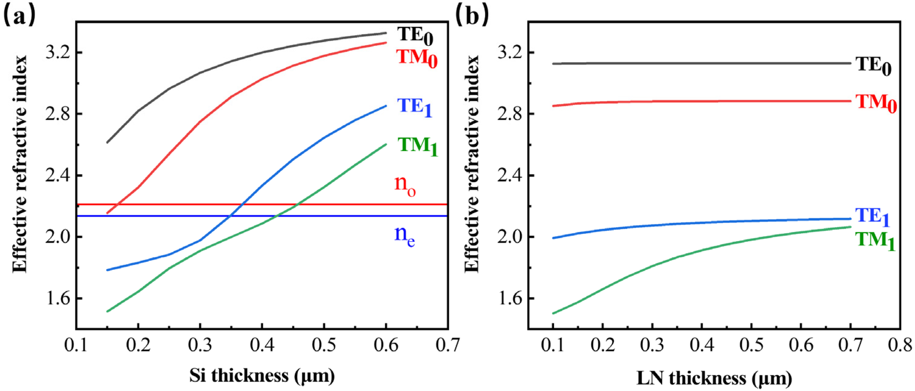
Firstly, the Si slab waveguide with LN film as the lower cladding was simulated. This simulation was based on the 1D FDTD model in Lumerical. The perfect match layer (PML) boundary condition is imposed, and the light propagation direction is along the y axis of the LN film. Figure 2a shows the effective refractive index (neff) of the TE slab mode and the TM slab mode varying with the Si film thickness when the LN film thickness is 500 nm. When neff of the TE1 (TM1) mode is larger than LN’s extraordinary (ordinary) refractive index, the higher-order TE (TM) slab mode appears in the silicon film. Based on this principle, the single-mode condition was extracted, and the Si film thickness should satisfy hsi ≤ 340 nm for the TE polarization and hsi ≤ 460 nm for the TM polarization. The effect of the LN film thickness on the single-mode condition of the Si slab mode was then investigated. As shown in Figure 2b, neff of the two fundamental modes are quite stable when the Si film thickness is 340 nm. neff of the TE1 mode increases slightly with the LN thickness increasing while the TM1 mode is heavily affected. However, neff of the TM1 mode is always smaller than no of LN when hLN ≤ 600 nm. This indicates that TM polarization can maintain the single-mode state in this thickness range.
In addition to the slab mode waveguide, the Si strip waveguide was also investigated. This simulation was based on the 2D FDTD model in Lumerical. The PML boundary condition is also imposed, and the propagation direction of the light is also parallel to the y-axis of the LN. Figure 3a shows neff of the first two-order TEi0 and TMi0 (i = 0, 1) modes with different waveguide widths when the thickness of Si and LN is 300 and 500 nm, respectively. Since the TE modes are commonly used to fabricate EOM, the single-mode condition of the TE mode was analyzed in detail. For the Si strip waveguide structure, the TE10 mode will cut off when its neff is smaller than ne of LN if LN is semi-infinitely thick. However, as the LN film thickness is only a few hundreds of nanometers in this structure, this structure may work as a Si strip-loaded waveguide with a Si strip on the top of the LN film [23,33]. For the strip-loaded waveguide, the TE10 mode and TM10 mode will couple to the LN TE0 slab mode when neff < neff (TE0). The insert image in Figure 3a is the Ez-component of TE10 simulated using the metal boundary condition when the Si height and width are 0.3 and 0.57 μm, respectively, indicating that the TE10 mode is coupling with the TE0 slab mode, which is called lateral leakage [30,31,34]. So, to guarantee that only the lowest-order TE mode can exist in this structure, it should satisfy neff (TE10) < neff (TE0). The red and blue horizontal lines in Figure 3a represent ne of LN and neff of the TE0 slab mode when the LN film is 500 nm. The intersection points of these two lines with neff of TE1 are the corresponding single-mode condition of the strip mode and strip-loaded mode when hsi = 300 nm. Therefore, the single-mode condition at different Si thicknesses was extracted as shown in Figure 3b. When hsi = 340 nm, Wsi should be smaller than 550 nm to prevent the appearance of the TE10 mode of both the strip waveguide and strip-loaded waveguide.
For the TE00 mode, it is difficult to identify the strip mode and the strip-loaded mode clearly in the Si-on-LNOI structure. In our opinion, ne of LN can be used to distinguish these two waveguide structures. The modes whose neff > ne of LN are strip modes; otherwise, they are strip-loaded modes. Figure 3c shows the separatrix of the strip mode and strip-loaded mode, and their mode fields are plotted in the insert images. To realize strip mode propagation in Si WG, Wsi should be wider than 310 nm when hsi = 340 nm.
Based on the above analysis, the Si film thickness should satisfy hsi ≤ 340 nm to fulfill the slab single-mode condition. Due to the small effect of the LN thickness on the Si waveguide when hLN > 300 nm, the LN thickness should be decided by the requirement of the LN devices. So, the LN film thickness was set as 500 nm since it is the standard thickness fabricated by our lab and the Si thickness was set as 340 nm. To achieve single-mode propagation in the Si strip waveguide, the waveguide width should satisfy Wsi > 310 nm and Wsi < 550 nm.
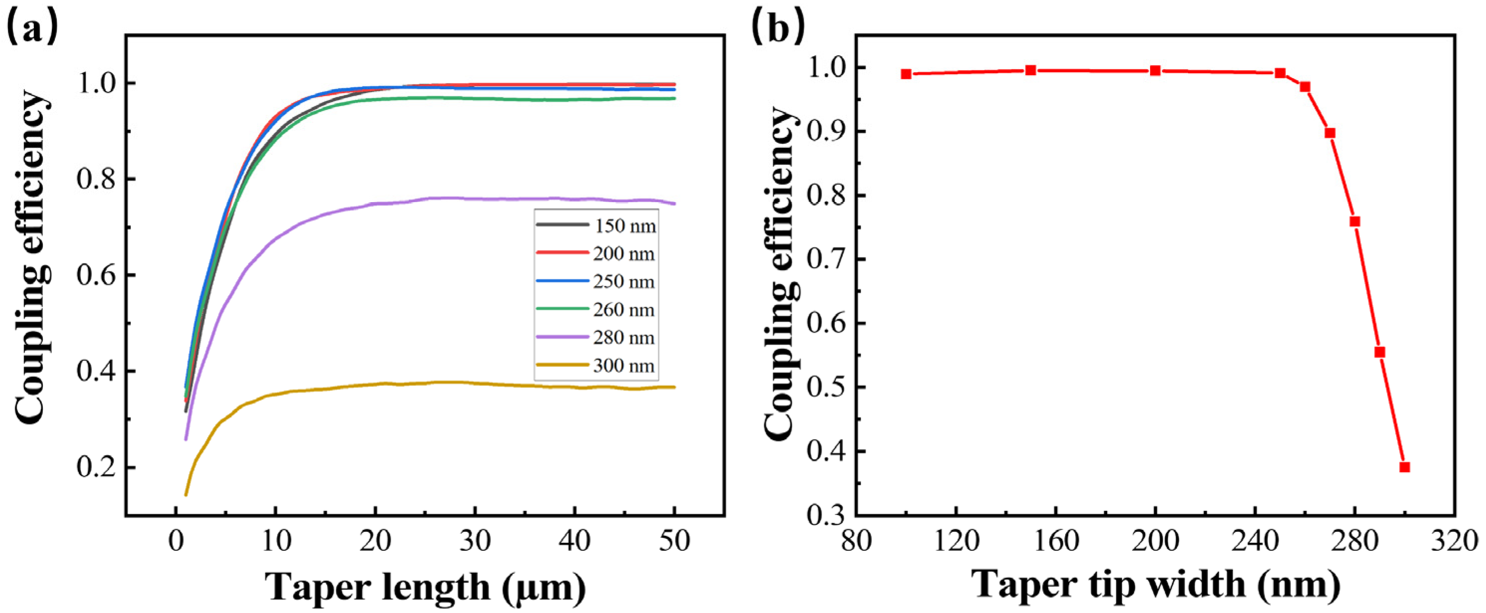
The VAC structure shown in Figure 1c was adapted to couple the light between the Si and LN layer. VAC is composed of a Si inverse taper and an LN ridge waveguide. In the simulation, the height and width of the Si waveguide were hsi = 340 nm and Wsi = 500 nm, which satisfy the single-mode condition of the strip Si waveguide. To simulate the practical LN waveguide, the LN ridge waveguide structure was used in the simulation. The PML boundary condition was imposed to consider the leakage to SiO2 and air cladding. The cross-section of the simulated LN WG is shown in Figure 1e. Both the ridge and the slab height were set to 250 nm. The width of the ridge top was 1 μm and the sidewall angle was 60 degrees. The effect of the tip width (Wtaper) and length (Ltaper) of the taper on the coupling efficiency was investigated. As shown in Figure 4a, the coupling efficiency of the TE00 mode increases when Ltaper increases. When Ltaper > 25 μm, the coupling efficiency can reach the maximum for different Wtaper. Figure 4b demonstrates that the coupling efficiency varies with Wtaper when Ltaper is equal to 25 μm. When Wtaper < 250 nm, the coupling efficiency is near 1 and barely changes. When Wtaper > 250 nm, the coupling efficiency declines quickly with Wtaper increasing. This indicates that Wtaper should be narrower than 250 nm to achieve highly efficient coupling between Si waveguides and LN waveguides. The high coupling efficiency helps VAC to be an optimized choice for hybrid photonic chips.

3. Structure Fabrication and Characterization

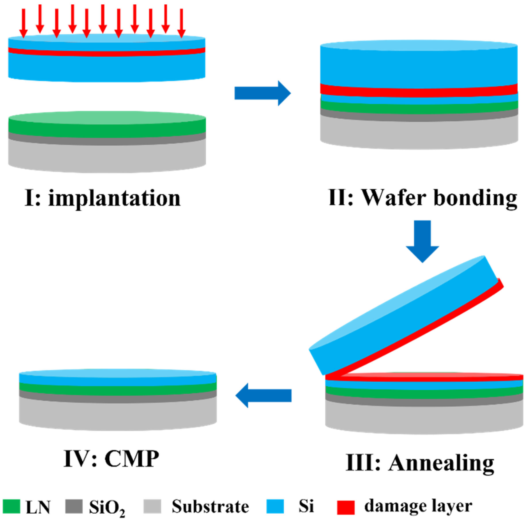
Based on the above analysis, the thickness of the top Si layer and the LN layer was designed to be 340 and 500 nm, respectively. The X-cut LNOI wafer with 500 nm LN and 2000 nm SiO2 was provided by the Novel Si Integration Technology (NSIT) Co., Ltd. A wafer-scale Si film was transferred onto the LNOI wafer using the ion-cut process. A schematic diagram of the fabrication of the Si-on-LNOI structure is shown in Figure 5. Firstly, 40 keV H+ implantation was performed on the 4-inch Si (100) wafer. The mean projected range Rp of the implanted ions is about 380 nm. About 40 nm was reserved for the CMP process to acquire the high-quality 340 nm Si layer. Then, the Si wafer was bonded with the LNOI substrate through plasma-activated bonding. The bonded pair was annealed at 450 °C for 8 h in the N2 atmosphere to transfer the Si film onto the LNOI substrate. Finally, the chemical mechanical polishing (CMP) process was implemented to reduce the surface roughness and remove the damage layer of the Si film. The thickness of the Si layer was characterized by white light interferometry. The surface topography of the Si film after CMP was characterized by atomic force microscopy (AFM). The microstructure of the Si-on-LNOI substrate was characterized by a cross-sectional transmission electron microscope (XTEM). The crystalline quality of the transferred LN and Si film was characterized by high-resolution X-ray diffraction (HRXRD) rocking curves on the LN (110) plane and Si (400) plane.
Figure 6a shows the image of the wafer-scale Si-on-LNOI structure. The Si film is quite intact with some voids due to wafer bonding. The mean thickness of the Si film is 329 nm and the film nonuniformity is ±1.3% as shown in Figure 6b. Figure 6c shows the AFM image of the Si film after CMP. The root mean square (RMS) roughness with a 5 μm × 5 μm area is only 0.089 nm, which is helpful for the fabrication of a low-loss waveguide.
The TEM images of the Si-on-LNOI structure are displayed in Figure 7. The thickness of the Si film is about 336 nm. The thickness difference measured by TEM and white light interferometry may be caused by the RI variation due to the implantation. The interface of the Si film and LN film is exhibited in Figure 7b. Between LN and Si, a native oxide of only 2.9 nm is presented. Near the interface, there is some lattice distortion in the LN film as shown in the green circle. It may be caused by the thermal mismatch of LN and Si due to the high-temperature process. Figure 7c shows the interface between LN and SiO2. The interface has no distortion, and the regular pattern shows that LN has an excellent single crystal quality.
The crystalline quality of the transferred Si film and LN layer was evaluated by HRXRD. The XRD rocking curve on the (400) plane of the Si film is plotted in Figure 8a. As the Si film and the Si substrate have the same orientation, two peaks in the XRD rocking curve of the (400) plane are observed. The higher and sharper peak is from the Si substrate while the other one is from the Si film. The full width at half-maximum (FWHM) of the Si film is calculated to be 120 arcsec while FWHM of the Si substrate is only 17.4 arcsec. The rise in FWHM is attributed to the H+ implantation damage. However, the film has a single-crystalline quality, which is better than the deposited poly or amorphous Si film. The rocking curve of the LN (110) plane after Si was transferred is shown in Figure 8b. FWHM of the LN film after annealing is 68.4 arcsec. This indicates the LN has an excellent single-crystalline quality.

4. Conclusions

In this paper, the Si-on-LNOI structure was simulated using the FDTD method and fabricated using the ion-cut process. The thickness of the Si film was optimized to be 340 nm based on the single-mode condition of the waveguide. The Si waveguide structure and the vertical adiabatic coupler between the Si waveguide and LN waveguide were simulated to verify the prospect of this structure. The 4-inch wafer-scale Si-on-LNOI structure was fabricated. The Si film exhibited a high uniformity of ±1.3% and smooth surface with an RMS roughness of 0.089 nm. The TEM results show that the structure possesses a sharp Si/LN interface and single-crystalline quality. The HRXRD result shows that the transferred Si film has a single-crystalline quality with a rocking curve FWHM of 120 arcsec. Further investigations will focus on the waveguides and hybrid device fabrication based on the Si-on-LNOI structure.

Author Contributions

Conceptualization, Y.C. and K.H.; methodology, Y.C., C.W., M.Z. and Z.L.; investigation, Y.C., X.Z., W.L. and X.K.; writing—original draft preparation, Y.C.; writing—review and editing, K.H. and X.O.; visualization, Y.C. All authors have read and agreed to the published version of the manuscript.

Funding

This research was funded by National Key R&D Program of China, grant number 2019YFB1803903, the National Natural Science Foundation of China, grant number 11905282, 62205363, Science and Technology Commission of Shanghai Municipality, grant number 21DZ1101500, the Key Research Project of Zhejiang Laboratory, grant number 2021MD0AC01, Strategic Priority Research Program of the CAS, grant number XDC07030200 and Shanghai Science and Technology Innovation Action Plan Program, grant number 22JC1403300.

Data Availability Statement

Not applicable.

Conflicts of Interest

The authors declare no conflict of interest.

References

  1. Okamoto, K.; Ishida, K. Fabrication of silicon reflection-type arrayed-waveguide gratings with distributed bragg reflectors. Opt. Lett. 2013, 38, 3530–3533. [Google Scholar] [CrossRef] [PubMed]
  2. Thomson, D.J.; Hu, Y.; Reed, G.T.; Fedeli, J.M. Low loss MMI couplers for high performance MZI modulators. IEEE Photonics Technol. Lett. 2010, 22, 1485–1487. [Google Scholar] [CrossRef] [Green Version]
  3. Liu, A.S.; Liao, L.; Rubin, D.; Nguyen, H.; Ciftcioglu, B.; Chetrit, Y.; Izhaky, N.; Paniccia, M. High-speed optical modulation based on carrier depletion in a silicon waveguide. Opt. Express 2007, 15, 660–668. [Google Scholar] [CrossRef] [PubMed] [Green Version]
  4. Gardes, F.Y.; Reed, G.T.; Emerson, N.G.; Png, C.E. A sub-micron depletion-type photonic modulator in silicon on insulator. Opt. Express 2005, 13, 8845–8854. [Google Scholar] [CrossRef]
  5. Liu, A.S.; Jones, R.; Liao, L.; Samara-Rubio, D.; Rubin, D.; Cohen, O.; Nicolaescu, R.; Paniccia, M. A high-speed silicon optical modulator based on a metal-oxide-semiconductor capacitor. Nature 2004, 427, 615–618. [Google Scholar] [CrossRef]
  6. Hochberg, M.; Baehr-Jones, T.; Wang, G.X.; Shearn, M.; Harvard, K.; Luo, J.D.; Chen, B.Q.; Shi, Z.W.; Lawson, R.; Sullivan, P.; et al. Terahertz all-optical modulation in a silicon-polymer hybrid system. Nat. Mater. 2006, 5, 703–709. [Google Scholar] [CrossRef] [Green Version]
  7. Koeber, S.; Palmer, R.; Lauermann, M.; Heni, W.; Elder, D.L.; Korn, D.; Woessner, M.; Alloatti, L.; Koenig, S.; Schindler, P.C.; et al. Femtojoule electro-optic modulation using a silicon-organic hybrid device. Light Sci. Appl. 2015, 4, e255. [Google Scholar] [CrossRef] [Green Version]
  8. Eltes, F.; Mai, C.; Caimi, D.; Kroh, M.; Popoff, Y.; Winzer, G.; Petousi, D.; Lischke, S.; Ortmann, J.E.; Czornomaz, L.; et al. A BaTiO3-based electro-optic pockels modulator monolithically integrated on an advanced silicon photonics platform. J. Light. Technol. 2019, 37, 1456–1462. [Google Scholar] [CrossRef] [Green Version]
  9. Guo, X.; Shao, L.; He, L.; Luke, K.; Morgan, J.; Sun, K.; Gao, J.; Tzu, T.-C.; Shen, Y.; Chen, D.; et al. High-performance modified uni-traveling carrier photodiode integrated on a thin-film lithium niobate platform. Photonics Res. 2022, 10, 1338–1343. [Google Scholar] [CrossRef]
  10. Vivien, L.; Marris-Morini, D.; Fedeli, J.M.; Rouviere, M.; Damlencourt, J.F.; El Melhaoui, L.; Le Roux, X.; Crozat, P.; Mangeney, J.; Cassan, E.; et al. Metal-semiconductor-metal Ge photodetectors integrated in silicon waveguides. Appl. Phys. Lett. 2008, 92, 151114. [Google Scholar] [CrossRef]
  11. Tian, B.; Wang, Z.; Pantouvaki, M.; Absil, P.; Van Campenhout, J.; Merckling, C.; Van Thourhout, D. Room temperature o-band DFB laser array directly grown on (001) silicon. Nano. Lett. 2017, 17, 559–564. [Google Scholar] [CrossRef]
  12. Xiang, C.; Liu, J.Q.; Guo, J.; Chang, L.; Wang, R.N.; Weng, W.L.; Peters, J.; Xie, W.Q.; Zhang, Z.Y.; Riemensberger, J.; et al. Laser soliton microcombs heterogeneously integrated on silicon. Science 2021, 373, 99–103. [Google Scholar] [CrossRef]
  13. Yonekura, K.; Jin, L.H.; Takizawa, K. Measurement of dispersion of effective electro-optic coefficients r13e and r33e of non-doped congruent LiNbO3 crystal. Jpn. J. Appl. Phys. 2008, 47, 5503–5508. [Google Scholar] [CrossRef]
  14. Luke, K.; Kharel, P.; Reimer, C.; He, L.Y.; Loncar, M.; Zhang, M. Wafer-scale low-loss lithium niobate photonic integrated circuits. Opt. Express 2020, 28, 24452–24458. [Google Scholar] [CrossRef]
  15. Zhang, M.; Wang, C.; Cheng, R.; Shams-Ansari, A.; Loncar, M. Monolithic ultra-high-Q lithium niobate microring resonator. Optica 2017, 4, 1536–1537. [Google Scholar] [CrossRef]
  16. Xu, M.; He, M.; Zhang, H.; Jian, J.; Pan, Y.; Liu, X.; Chen, L.; Meng, X.; Chen, H.; Li, Z.; et al. High-performance coherent optical modulators based on thin-film lithium niobate platform. Nat. Commun. 2020, 11, 3911. [Google Scholar] [CrossRef]
  17. Zhang, M.; Wang, C.; Kharel, P.; Zhu, D.; Lončar, M. Integrated lithium niobate electro-optic modulators: When performance meets scalability. Optica 2021, 8, 652–667. [Google Scholar] [CrossRef]
  18. He, M.B.; Xu, M.Y.; Ren, Y.X.; Jian, J.; Ruan, Z.L.; Xu, Y.S.; Gao, S.Q.; Sun, S.H.; Wen, X.Q.; Zhou, L.D.; et al. High-performance hybrid silicon and lithium niobate mach-zehnder modulators for 100 gbit s−1 and beyond. Nat. Photonics. 2019, 13, 359–364. [Google Scholar] [CrossRef] [Green Version]
  19. Wang, C.; Zhang, M.; Chen, X.; Bertrand, M.; Shams-Ansari, A.; Chandrasekhar, S.; Winzer, P.; Loncar, M. Integrated lithium niobate electro-optic modulators operating at cmos-compatible voltages. Nature 2018, 562, 101–104. [Google Scholar] [CrossRef]
  20. Wang, D.; Ding, T.T.; Zheng, Y.L.; Chen, X.F. Cascaded sum-frequency generation and electro-optic polarization coupling in the PPLNOI ridge waveguide. Opt. Express 2019, 27, 15283–15288. [Google Scholar] [CrossRef]
  21. Mackwitz, P.; Rusing, M.; Berth, G.; Widhalm, A.; Muller, K.; Zrenner, A. Periodic domain inversion in x-cut single-crystal lithium niobate thin film. Appl. Phys. Lett. 2016, 108, 152902. [Google Scholar] [CrossRef]
  22. Chen, L.; Nagy, J.; Reano, R.M. Patterned ion-sliced lithium niobate for hybrid photonic integration on silicon. Opt. Mater. Express 2016, 6, 2460–2467. [Google Scholar] [CrossRef]
  23. Wang, Y.W.; Chen, Z.H.; Cai, L.T.; Jiang, Y.P.; Zhu, H.B.; Hu, H. Amorphous silicon-lithium niobate thin film strip-loaded waveguides. Opt. Mater. Express 2017, 7, 4018–4028. [Google Scholar] [CrossRef]
  24. Jian, J.; Xu, P.F.; Chen, H.; He, M.B.; Wu, Z.R.; Zhou, L.D.; Liu, L.; Yang, C.C.; Yu, S.Y. High-efficiency hybrid amorphous silicon grating couplers for sub-micron-sized lithium niobate waveguides. Opt. Express 2018, 26, 29651–29658. [Google Scholar] [CrossRef] [PubMed]
  25. Weigel, P.O.; Zhao, J.; Fang, K.; Al-Rubaye, H.; Trotter, D.; Hood, D.; Mudrick, J.; Dallo, C.; Pomerene, A.T.; Starbuck, A.L.; et al. Bonded thin film lithium niobate modulator on a silicon photonics platform exceeding 100 GHz 3dB electrical modulation bandwidth. Opt. Express 2018, 26, 23728–23739. [Google Scholar] [CrossRef] [Green Version]
  26. Wang, J.; Xu, S.; Chen, J.; Zou, W. A heterogeneous silicon on lithium niobate modulator for ultra-compact and high-performance photonic integrated circuits. IEEE Photonics J. 2021, 13, 4900112. [Google Scholar] [CrossRef]
  27. Li, Q.; Zhu, H.; Zhang, H.; Cai, L.; Hu, H. Phase modulators in hybrid silicon and lithium niobate thin films. Opt. Mater. Express 2022, 12, 1314–1322. [Google Scholar] [CrossRef]
  28. Cai, J.; Guo, C.; Lu, C.; Lau, A.P.T.; Chen, P.; Liu, L. Design optimization of silicon and lithium niobate hybrid integrated traveling-wave mach-zehnder modulator. IEEE Photonics J. 2021, 13, 2200206. [Google Scholar] [CrossRef]
  29. Sun, S.; He, M.; Xu, M.; Gao, S.; Yu, S.; Cai, X. Hybrid silicon and lithium niobate modulator. IEEE J. Sel. Top. Quantum Electron. 2021, 27, 3300112. [Google Scholar] [CrossRef]
  30. Xu, Q.; Shao, Y.X.; Piao, R.Q.; Chen, F.; Wang, X.; Yang, X.F.; Wong, W.H.; Pun, E.Y.B.; Zhang, D.L. A theoretical study on rib-type photonic wires based on LiNbO3 thin film on insulator. Adv. Theory Simul. 2019, 2, 1900115. [Google Scholar] [CrossRef]
  31. Yu, X.R.; Wang, M.K.; Li, J.H.; Wu, J.Y.; Hu, Z.F.; Chen, K.X. Study on the single-mode condition for x-cut LNOI rib waveguides based on leakage losses. Opt. Express 2022, 30, 6556–6565. [Google Scholar] [CrossRef]
  32. Villa, J.J. Additional data on refractive-index of silicon. Appl. Opt. 1972, 11, 2102–2103. [Google Scholar] [CrossRef]
  33. Zhang, P.; Huang, H.J.; Jiang, Y.H.; Han, X.; Xiao, H.F.; Frigg, A.; Nguyen, T.G.; Boes, A.; Ren, G.H.; Su, Y.K.; et al. High-speed electro-optic modulator based on silicon nitride loaded lithium niobate on an insulator platform. Opt. Lett. 2021, 46, 5986–5989. [Google Scholar] [CrossRef]
  34. Saitoh, E.; Kawaguchi, Y.; Saitoh, K.; Koshiba, M. TE/TM-pass polarizer based on lithium niobate on insulator ridge waveguide. IEEE Photonics J. 2013, 5, 6600610. [Google Scholar] [CrossRef]
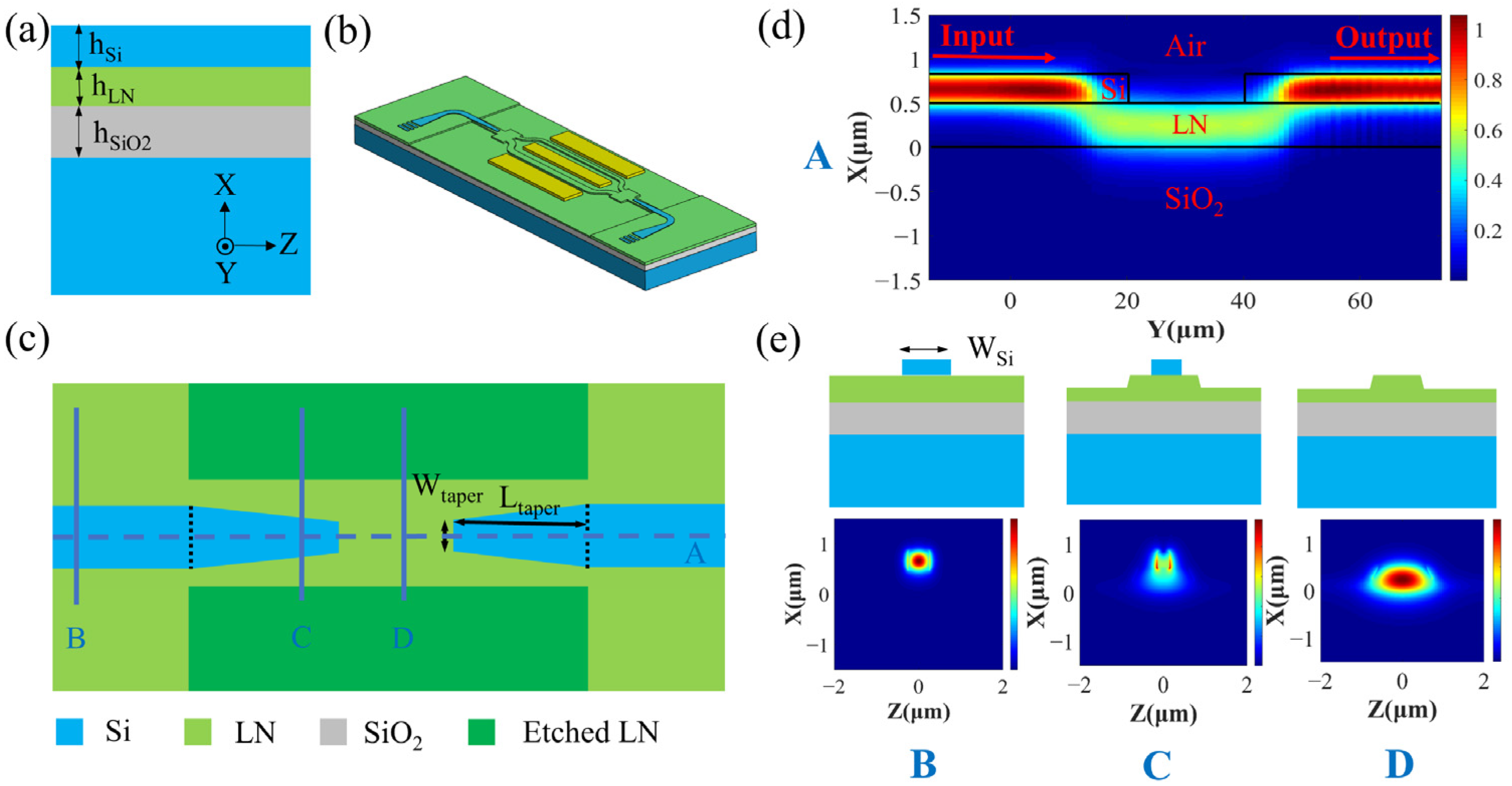
Figure 1. (a) Schematic diagram of the Si-on-LNOI structure. (b) Schematic diagram of the hybrid Si and LN electro-optical modulator. (c) The top view of VACs with two Si tapers and an LN waveguide. (d) The simulated light propagation field of the VAC structure at cross-section A of (c). (e) The cross-section of B, C, and D in (c) and the corresponding simulated TE00 mode field.
Crystals 12 01477 g001
Figure 2. (a) neff of the first two-order Si slab modes with different Si film thicknesses when the LN thickness is 500 nm. (b) neff of the first two-order Si slab modes with different LN film thicknesses when the Si thickness is 340 nm.
Crystals 12 01477 g002
Figure 3. (a) neff of the first two-order TEi0 and TMi0 (i = 0, 1) modes with different waveguide widths; inset: the Ez-component of the TE10 mode when the Si waveguide height and width are 0.3 and 0.57 μm, respectively; (b) Single-mode condition of the Si strip waveguide and Si strip-loaded waveguide for TE polarization. (c) The separatrix of the strip fundamental mode and strip-loaded fundamental mode; inset: the mode filed of the strip-loaded WG mode (lower left corner) and the strip WG mode (upper right corner).
Crystals 12 01477 g003
Figure 4. (a) The VAC coupling efficiency at different Si inverse taper tip widths and lengths. (b) The coupling efficiency varies with the Si inverse taper tip width when the coupling length is 25 μm.
Crystals 12 01477 g004
Figure 5. A schematic diagram of the fabrication process of the Si-on-LNOI structure.
Crystals 12 01477 g005
Figure 6. (a) Image of the wafer-scale Si-on-LNOI structure. (b) Film thickness mapping of the Si film. (c) The AFM test results of the Si film after CMP.
Crystals 12 01477 g006
Figure 7. XTEM images of the Si-on-LNOI structure: (a) the overview of the Si-on-LNOI structure, (b) the interface of the Si film and the LN film, and (c) the interface of the LN film and the SiO2 film.
Crystals 12 01477 g007
Figure 8. (a) XRD rocking curve result of the Si (400) plane; (b) XRD rocking curve result of the LN (110) plane.
Crystals 12 01477 g008
Publisher’s Note: MDPI stays neutral with regard to jurisdictional claims in published maps and institutional affiliations.