1. Introduction
Lightweight materials with high strength are vigorously required in aviation sector. The weight reduction of engine parts improves in fuel efficiency in service conditions, which can be gratified by Al matrix composites (AMC) without compromising the mechanical properties [
1]. AMC is one such composite which advances the performance of the materials and prolongs the lifetime of the component in service condition. At large, AMCs can provide/induce the properties of reinforcement in matrix. Al 7xxx series alloys comprise Zn as major alloying elements. The role of Zn is to improve the mechanical and corrosion properties of the material by forming as a solid solution by placing in the octahedral voids of the Al lattice. Al-Zn alloys could be suitable for wings of the planes [
2]. The reduction in % elongation is one of the cataclysmic botches in the components which break down in service life without any indication. In order to hold the material as ductile as it is in nature, it is advisable to add metallic reinforcement particles within it (Here, Zn (10 wt.%)), besides ceramic reinforcement. Comparatively, among the oxides and borides ceramic reinforcement particles, carbides can provide better strength to the matrix in economical way of pursuit [
3]. The carbide particles reinforcement in the AMCs leads to improvement in the strength of the final product. On the contrary, the agglomeration of reinforcement deprives the elongation of the final product by restricting the deformation plastically of the AMC. Titanium carbide is a well-known material of pursuit which has higher load carrying ability and better frictional resistance as a reinforcement [
4].
The prevention of reaction between ceramic particles with Al matrix is an uphill battle. Therefore, a suitable AMC manufacturing method must be followed for the production of AMC components. Numerous ways are being utilised to fabricate AMCs. Liquid metallurgy is a notable technique for AMC fabrication. Nevertheless, reaction between matrix and reinforcement leads to the form of intermetallic compounds (IMC). Therefore, solid state processing techniques must be followed to elude the IMCs formation, among which Friction Stir Processing (FSP) is a versatile one to avoid IMC formation and to obtain better properties; however, the costs of tool and mass production are unmanageable in this method. Accumulative Roll Bonding (ARB) is another way to produce the AMC; nonetheless, the holding ductility property is quite challenging in this technique.
The powder metallurgy is a promising technique to produce AMCs by avoiding cluster formation among introduced second phase ceramics, in which mechanical alloying produces nanocomposite (NC) particles with uniform distribution of reinforcement particles in Metal Matrix Composites (MMCs). During mechanical alloying, the high energy collision of the un-milled AMC particles makes them to bond temporarily and finally makes them to get fractured. The fracturing of matrix particles was not only due to high energy collision of balls within the vial but also to the introduced reinforcement particles acts as a milling media inside the vial and breaks the matrix particles. Hence the NC powder particles exhibited superior properties to unreinforced ones [
5,
6,
7,
8]. Spark plasma sintering (SPS) is an advanced compaction technique, which tightens the loosen powder particles by applying pulsed current with high pressure. In SPS, the IMC formation can be restricted, and ductility can be preserved as much as in the parent matrix material [
9,
10,
11].
Based on literatures available, there is no research conducted on [Al–10Zn]–TiC nanocomposites. Hence, the present work examines the mechanical and compression behaviour of nanocomposites after 20 h of MA and SPS and correlated using advanced characterization techniques.
2. Experimental Procedure
2.1. Materials
The materials used in this work are commercially pure Al (99.5% purity) as matrix material, Zn (99.5% purity) as alloying element to form solid solution and TiC ceramic particles (>99% purity) as reinforcement, procured from M/s (Sigma-Aldrich, Burlington, VT, USA). The mean particle size of the as received powder particles such as Al, Zn and TiC are ~44 μm, ~20 μm and ~70 nm, respectively.
2.2. Ball Milling Processes of Al/TiC Powders
[Al–10Zn]–TiC nanocomposites were synthesised using High Energy Ball Milling (HEBM). The wt.% of TiC nanoparticles varied from 3% to 12% with the interval of 3 wt.%; to make a comparison, the unreinforced nanocrystalline matrix is considered.
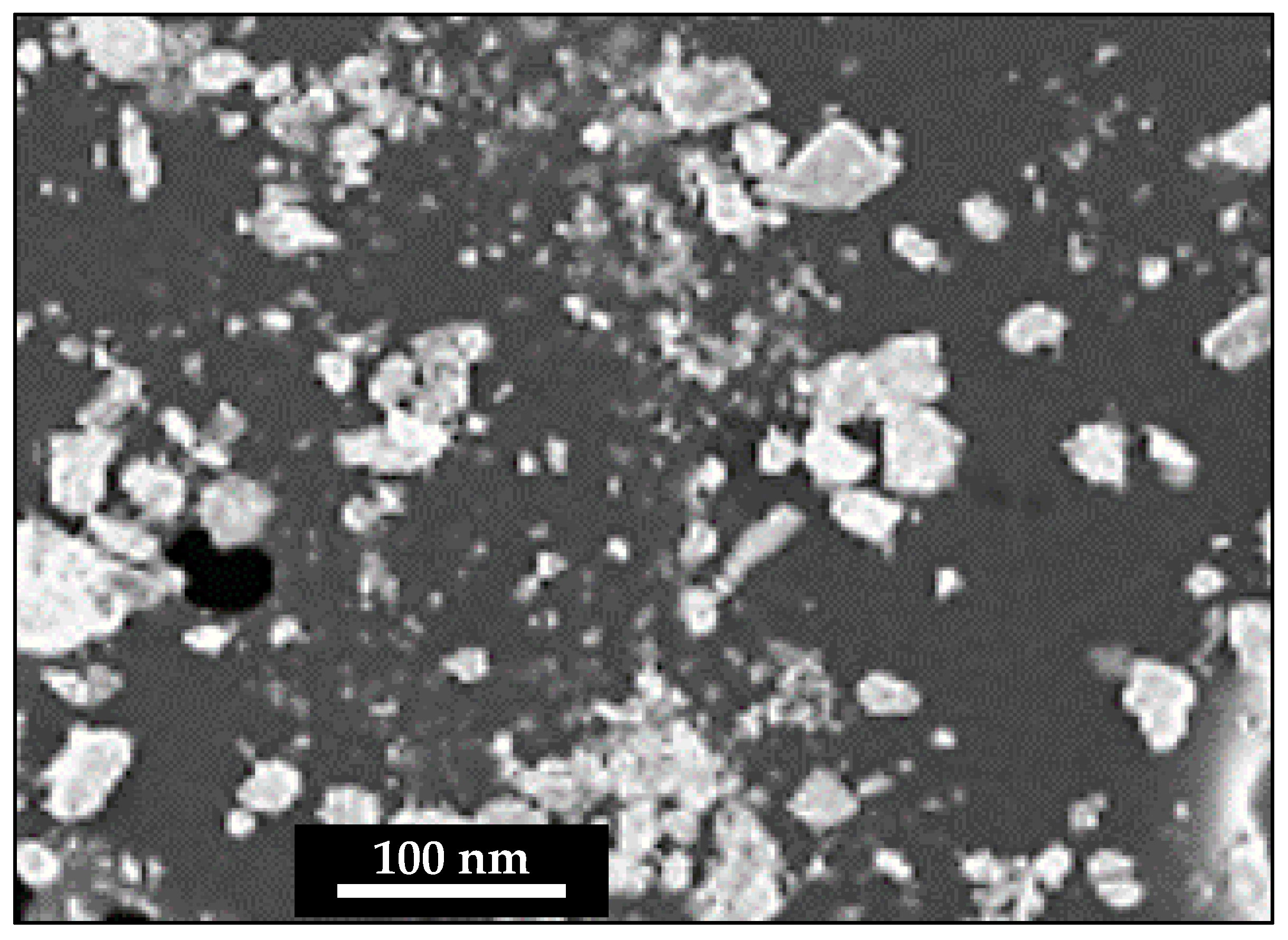
Figure 1 shows the SEM image of as received TiC nanoparticles. Initially, Al with 10 Zn is conventionally milled using Low Energy Ball Milling (LEBM) to for Al–10Zn alloy. Toluene (C
6H
5CH
3) process control agent is used during MA to elude the intermetallic compounds formation, agglomeration and breaking the cold-welded particles. Twelve tungsten balls (each 40 g in mass) of diameter 10 mm with 40 g mass of LEBM with reinforcement particles and toluene were poured in the vials. Ratio of 10:1 was the chosen for Balls to Powder Ratio (BPR) [
8]. In HEBM, vial and plate speed were kept as 280 rpm and 105 rpm for the duration of 20 h; nevertheless, to get rid of temperature rise inside the bowl, working time and down time were set as 45 min and 15 min continuously. The MA process occurring during HEBM specifies the vial and plate directions are opposite to each other and motion of the ball inside the vial.
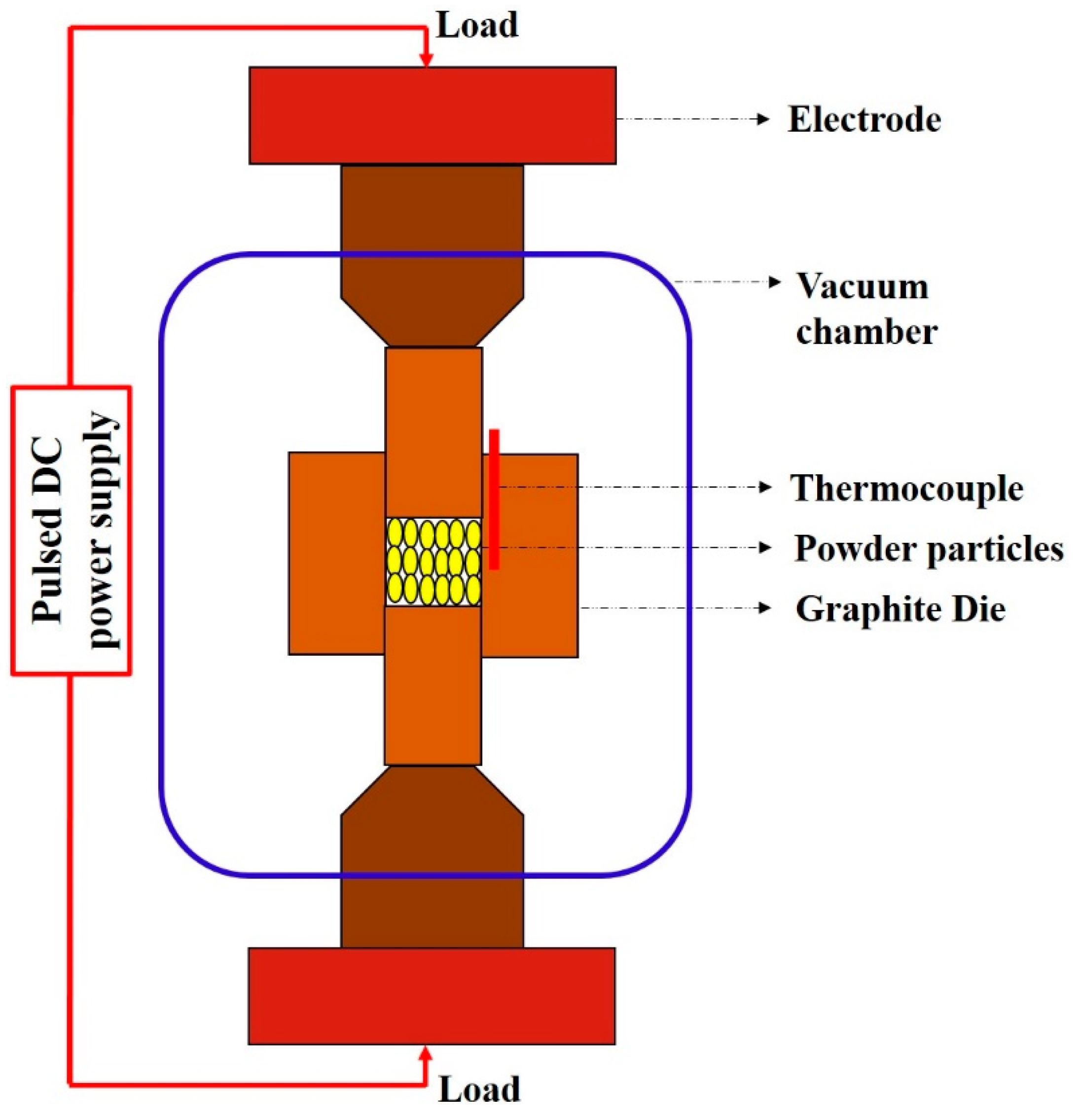
MA nanocomposite powder particles were uniformly loaded over the bottom punch Gr die to get the final product of diameter 20 mm and height 20 mm. The SPS experiments were carried out at 950 °C and at a pressure of 50 MPa under vacuum of 1.33 Pa for the sintering duration of 15 minutes. The temperature and pressure combinations reported here are the optimized parameters that resulted in superior mechanical properties without any porosities.
Figure 2 shows the schematic representation of SPS.
2.3. Characterization and Testing
The phase formation of the SPS sintered nanocomposite bulk specimens were analysed through X-ray diffraction of Shimadzu XRD 6000 (Shimadzu, Kyoto, Japan), of CuKa radiation source operating at 40 kV and 30 mA. The set scanning range and scanning speed are 20–80° and 2°/min. The field emission scanning electron microscope of JEOL JSM6390 (JEOL Ltd., Tokyo, Japan) has been utilised to observe the distribution, agglomeration and porosities present in the material. The dislocation, homogeneity and ultrafine nature were studied with the help of Transmission electron microscope (TEM) analysis using JEOL JEM 2100 (JEOL Ltd., Tokyo, Japan). The hardness of bulk specimens was measured using Vickers’s micro-hardness test in which pyramid shaped diamond indenter of load and dwell time of 25 g for 15 s. The compression test was carried out using Hounsfield H25KS (Tinius Olsen, Redhill, UK), ambient temperature with strain rate of 10−4 s−1. The mechanism of the deformed specimens were studies using fracture morphologies with the support of FE-SEM.
3. Results and Discussions
3.1. Phase Analysis
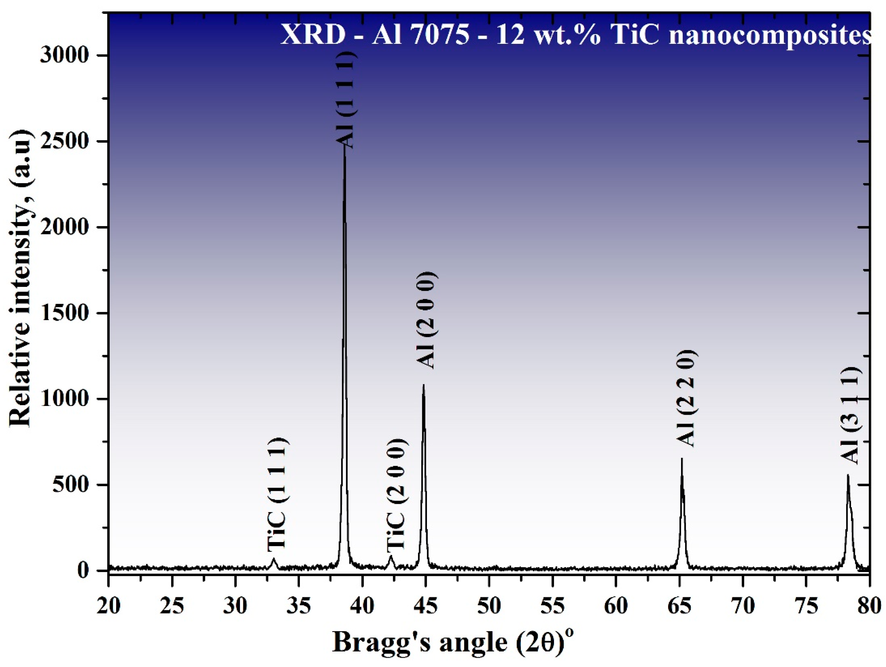
Figure 3 shows the XRD profile of 12 wt.% TiC reinforced [Al–10Zn] nanocomposites. The presence of TiC particulates was confirmed in reinforced nanocomposite. The witnessed TiC peaks corresponded to the diffraction plane (1 1 1) and (2 0 0) at the angle 32.90 and 44.82°. The matrix peak positions are inconsistent in the fabricated nanocomposite which was possibly because of lattice distortion of the Al by reinforcement particles. In 12 wt.% reinforced nanocomposites, Al peaks had moved from their original position when compared with pure Al, which was due to the difference between the lattice constant of Al, Zn and TiC nanoparticles. The results not only indicated the existence of reinforcement content but also the absence of intermetallic compounds. Zn was not present in the Al matrix, which confirmed the formation of Al–Zn alloy, and the absence of Zn was due to the settlement of Zn in octahedral voids of Al matrix [
12].
3.2. Observation of TiC Distribution
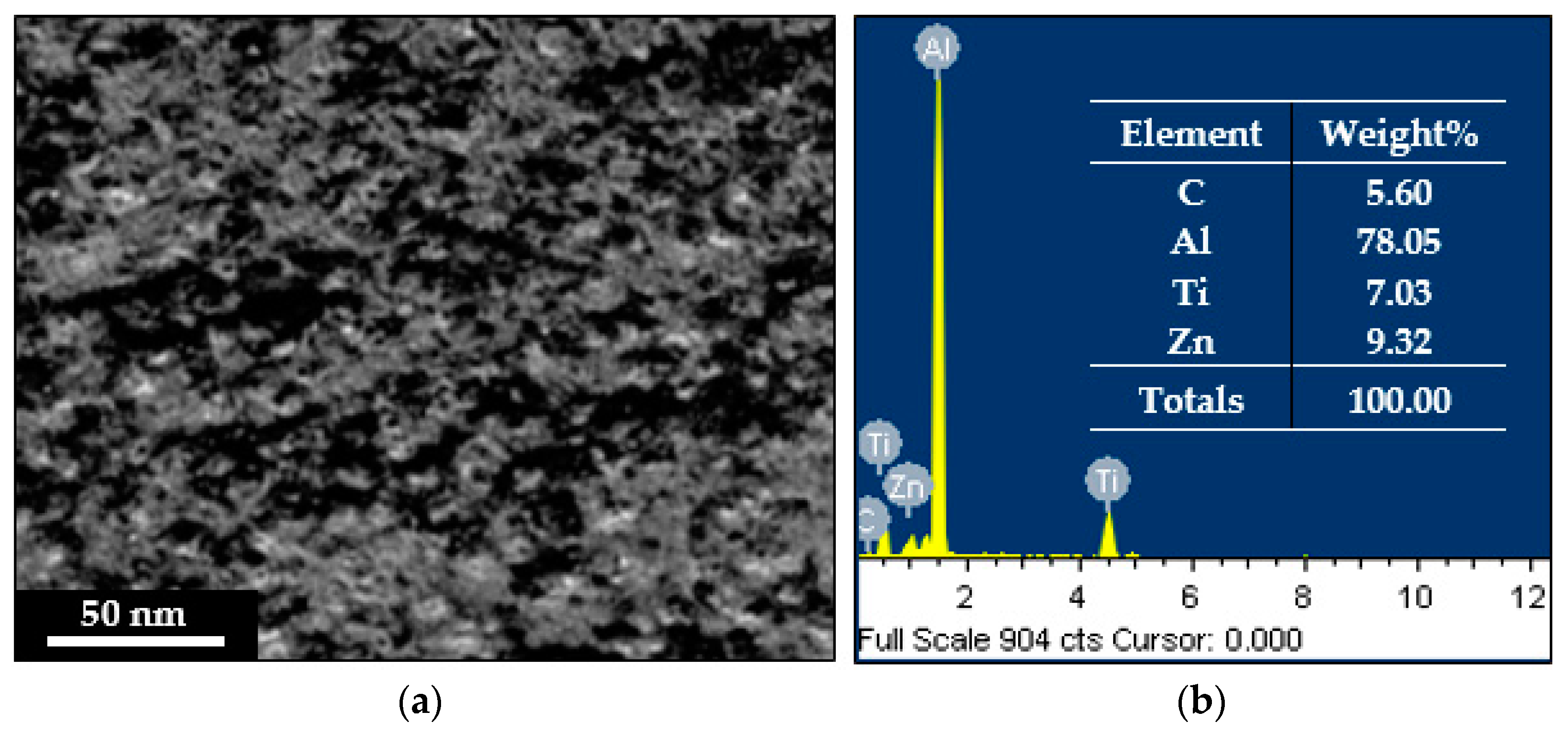
Figure 4 depicts the SEM morphology of [Al–10Zn]–12 wt% TiC nanocomposites. There is uniform scattering and embedding of TiC nanoparticles in the matrix, depicted from the micrograph. The centrifugal action produced inside the vial imported high energy to the powder particles during MA led to the dispersion uniformly. In addition, there was no cluster nature and porosities witnessed in the 12 wt.% TiC nanocomposites. The porosities on the nanocrystalline matrix were lost by the SPS processing. Hence, an improvement in mechanical behaviour such as hardness and compression strength can be attained in the established nanocomposite. In this regard, the distribution of TiC nanoparticles and grain size plays a main role in the nanocrystalline Al matrix with TiC nanoparticles [
13].
3.3. Grain Size Examination through EBSD Analysis
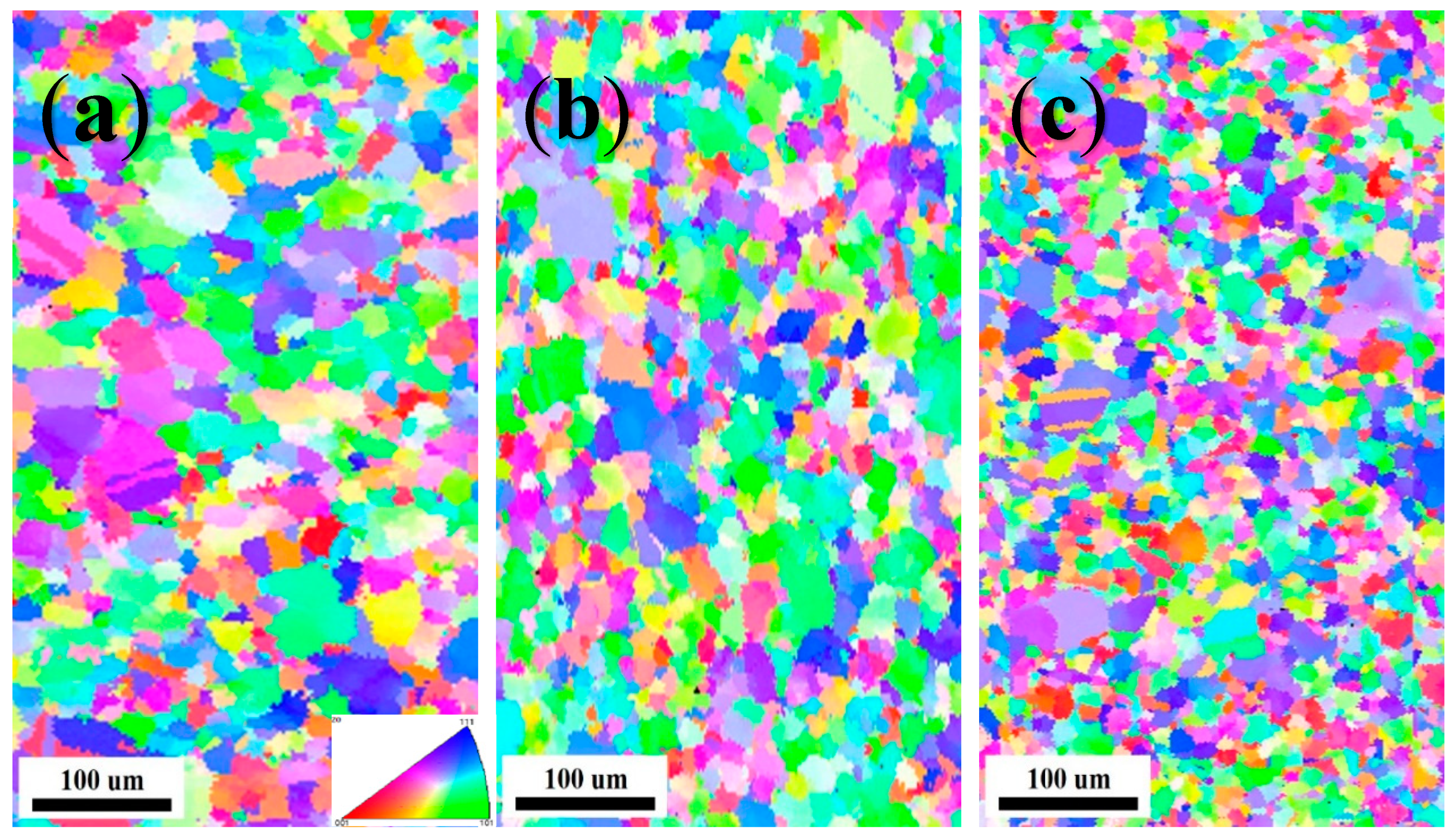
The EBSD examination results are displayed in
Figure 5a–c for unreinforced, 6 and 12 vol.% TiC nanoparticles reinforced [Al–10Zn] nanocomposites. The 0, 6 and 12 vol.% TiC nanoparticles specimen comprises the grain size of 55 ± 12 μm (coarser grains), 22 ± 09 μm (finer and ultrafine grains) and 9 ± 2 μm (ultrafine grains alone), respectively. The substantial decrease in grain size was incommensurate with hard TiC nanoparticles addition. According to Zener pinning effect, the reinforced TiC nanoparticles augmented the nucleation of grains during recrystallization. Additionally, with increase in passes, introduced TiC nanoparticles were reordered equivalently in the nugget zone by rigorously refining of larger sized grains. In the fabricated nanocomposites, the grains were refined relentlessly owing to the dispersion of TiC nanoparticles throughout the specimen, MA process and optimised SPS parameter [
13].
3.4. Examining the Morphologies of Matrix Grains and TiC Nanoparticles
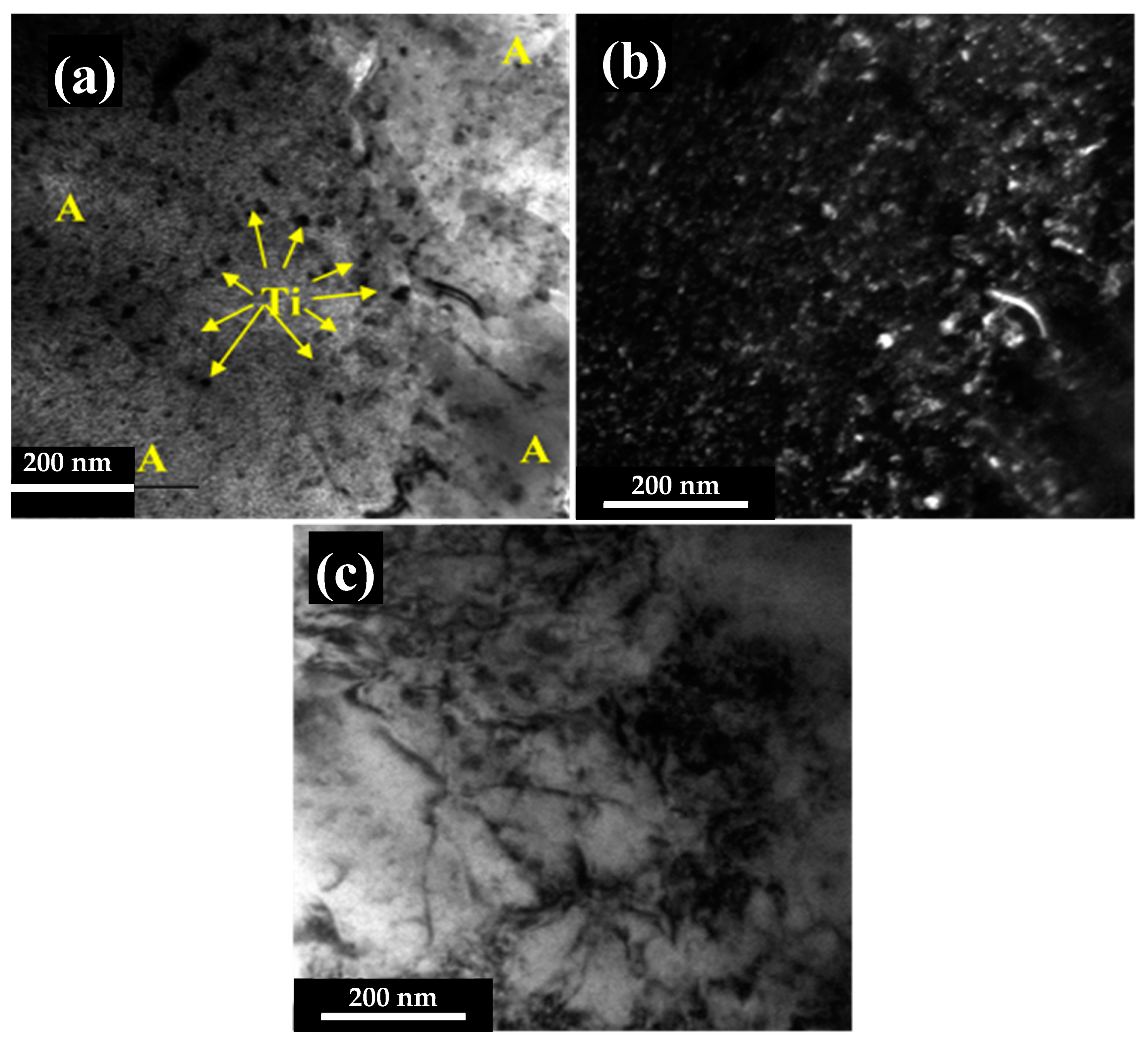
In addition to the observation of TiC nanoparticles dispersion, morphologies of matrix grains and TiC nanoparticles along with the strengthening factor such as dislocations were observed using TEM analysis.
Figure 1 showed the FESEM microstructural morphologies of TiC nanoparticles in as received condition.
Figure 6a–c displays the TEM micrograph of [Al–10Zn]–12 wt% TiC nanocomposites whose dislocations alone could be identified through Bright Field Image (BFI) with respective Dark Field Image (DFI) and BFI to show the dislocation, because of the fact that any metal or alloy or composite is prone to get dislocations when deformation takes place. The obtained results ensued from the distribution of reinforcement particles in the matrix which ensured the uniform distribution of the same and embedded well in the Al matrix. This is due to the effect of HEBM occurring during the mechanical alloying process. The distance between the reinforcement particles had decreased because of increase in reinforcement addition up to 12 wt.%. The presence of clear surface confirmed the absence of defects such as voids, cracks and clustering. It is known that the yield strength of the composite entirely depends upon on the interfacial bond strength, which helps to transmit the load to the reinforcement from the matrix.
Figure 6c depicts the dislocation, which is due to addition of second phase particles (TiC nanoparticles) [
14,
15].
3.5. Vickers Micro-Hardness Examination
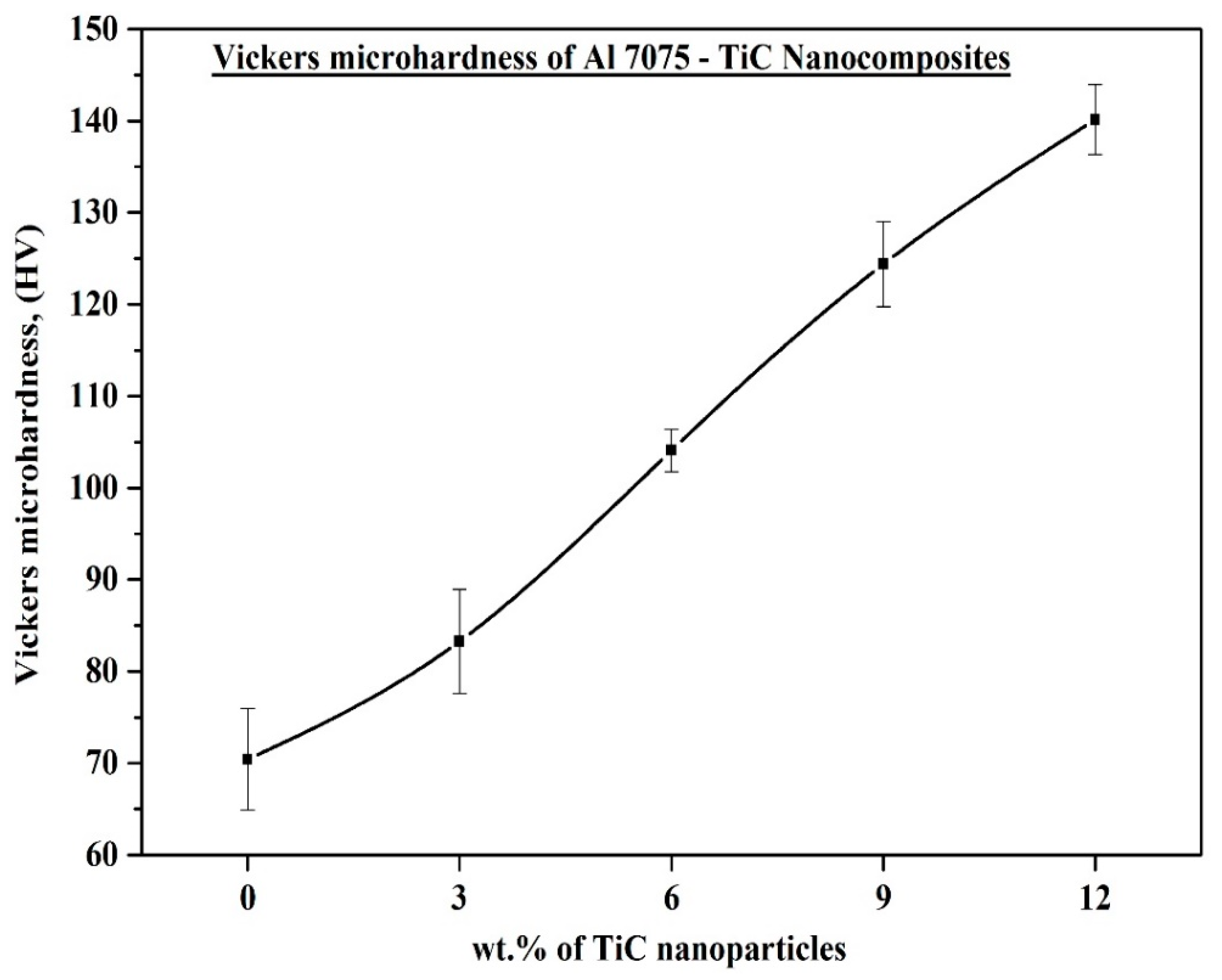
The Vickers microhardness result of [Al–10Zn]–x wt% TiC (x = 0, 3, 6, 9 and 12) nanocomposites is shown in
Figure 7. The measured values kept on increasing; this trend showed the hardness of the SPS nanocomposite specimens was increased drastically with the function of TiC addition in the (Al–10Zn) matrix. The hardness measurements of the unreinforced crystalline matrix and 3, 6, 9 and 12 wt.% TiC nanocomposites are 70, 84, 105, 124 and 140 HV, in average. The reason for the hardness improvement was due to the following factors: (a) Grains were refined both in the nanocrystalline matrix and reinforced nanocomposites. The reinforced TiC nanoparticles had acted as a fence to the nucleation and formation of matrix grains which lead to the hindrance of the grain growth. (b) The uniform scattering and embedment of TiC nanoparticles in the Al matrix is prone to resist the deformation and withstanding ability of the externally applied loads. (c) The work hardening effect created during HEBM strengthened the bonding between the base matrix particles and reinforcement particles. (d) The greater interfacial bonding between the Al matrix and TiC nanoparticles was due to SPS process engendered while HEBM, and (e) nonattendance of defects like porosities in the Al–TiC interface and in the surface of the sintered specimens [
16].
3.6. Compression Behaviour Examination
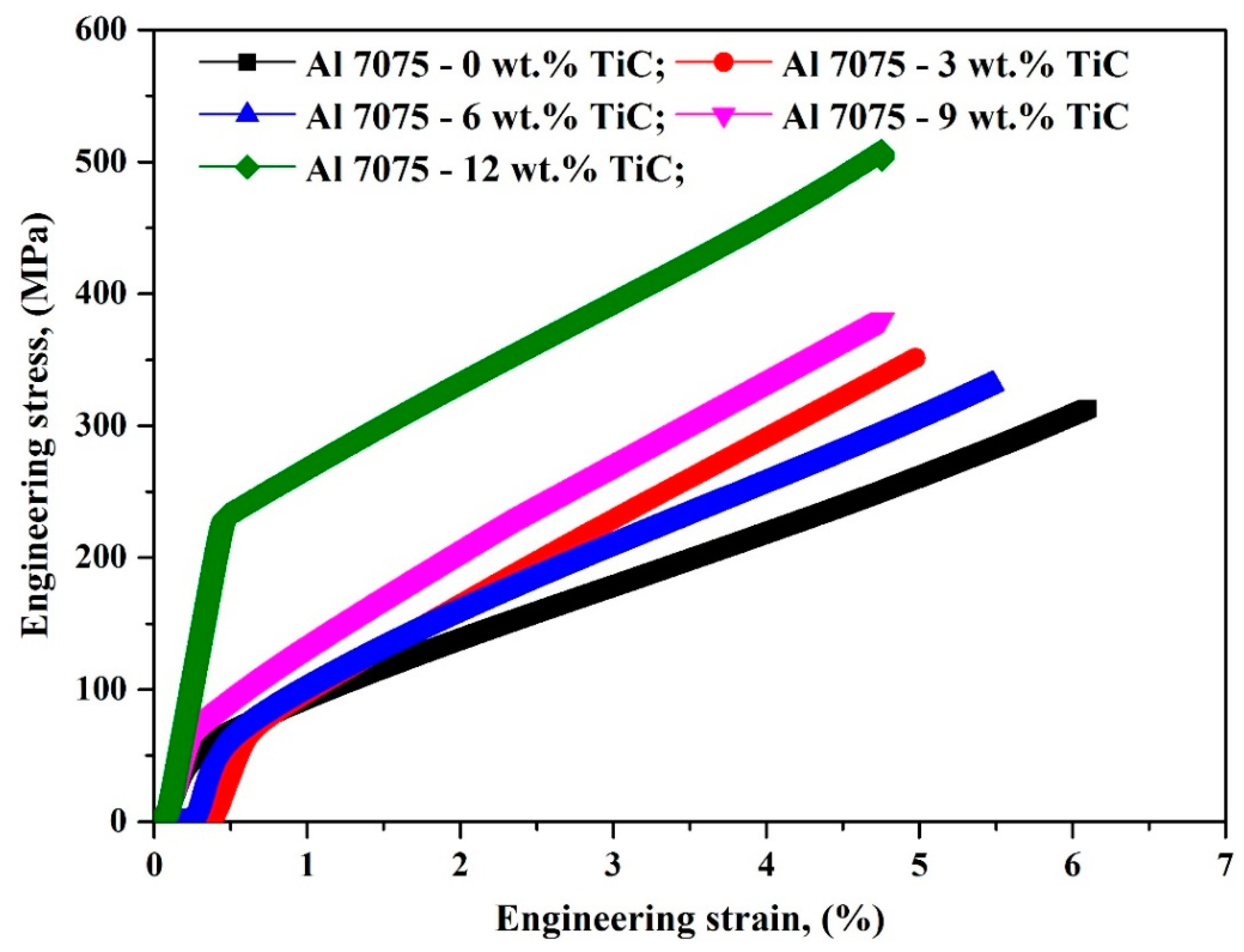
Figure 8 shows the compressive stress strain curves of [Al–10Zn]–TiC nanocomposites. The values of ultimate compressive stress (UCS) and compressive yield strength (CYS) of reinforced composites are increasing almost linearly with respect to reinforcement addition. The compressive stress strain curves of 0, 3, 6, 9 and 12 wt.% TiC nanocomposites attain the UCS of 312.99, 331.42, 350.81, 380.76 and 501.22 MPa. This is mainly due to the better bond strength at the matrix and reinforcement interface, wettability of reinforcement particles around the Al and the uniform dispersion of TiC particles the fabricated nanocomposites. Discussion on strengthening mechanisms that are likely to have occurred in the present investigation is given below. (a) Grain boundary strengthening, which is the result of grain refinement strengthening and grain boundary pinning. In this investigation, TiC nanoparticles in the Al matrix obstruct the motion of dislocation in the boundary. The grain refinement strengthening contribution can be expressed according to the Hall–Petch relation. (b) Dislocation strengthening: Thermal mismatch theory explains that temperature mismatch produces stress in the composites and leads to the variation in strength of the material. The incorporation of TiC nanoparticles in the composite results in improvement in dislocation density and increases the yield strength. Dislocations can be formed during solidification of the molten pool due to thermal mismatch among Al and TiC particulates. (c) Dispersion strengthening: In Orowan dispersion strengthening mechanism, the composite strength could be improved without decrease in ductility.
The reinforcement particles that hinder the dislocation motions generate a dislocation loop around the particles. Further migration of dislocation is prevented by generated loops [
17,
18].
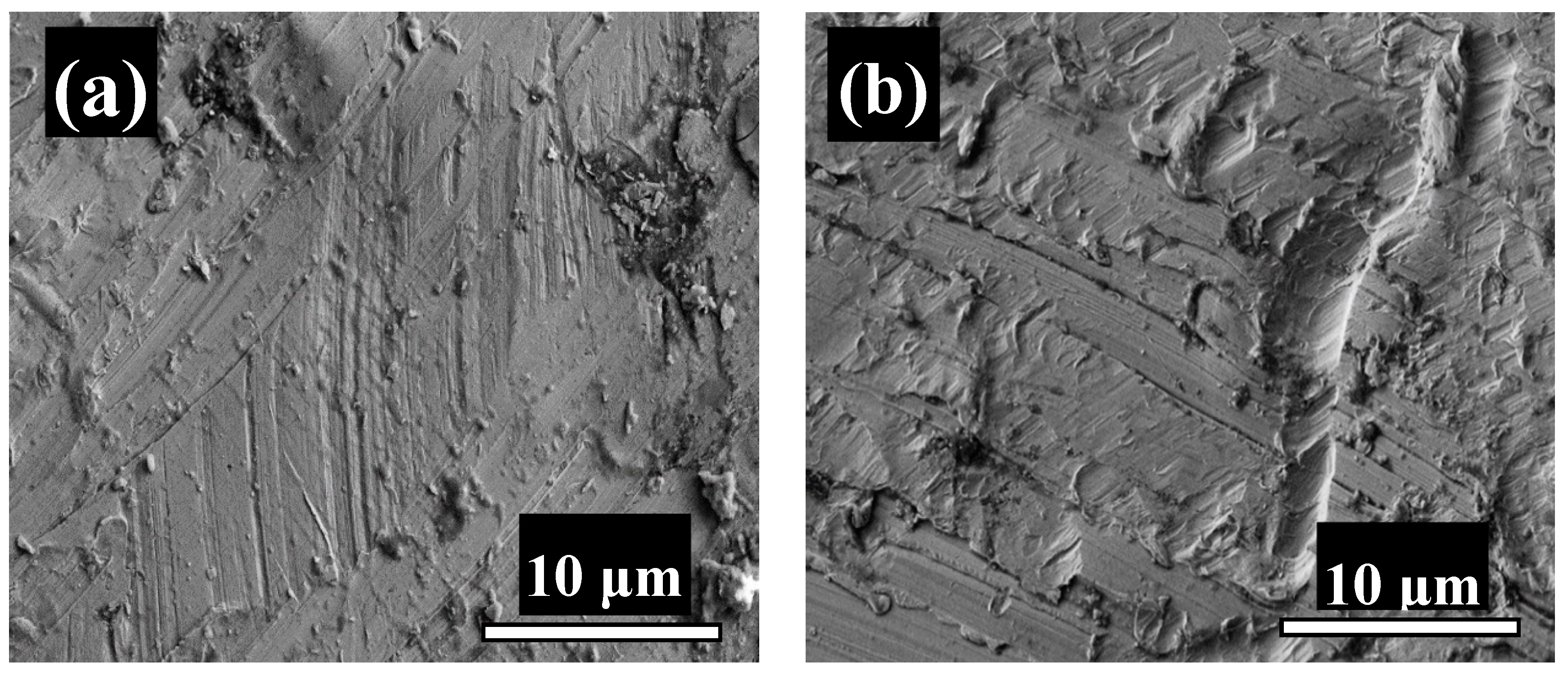
Figure 9a,b shows the fractography (SEM) of after compression test specimens (0 and 12 wt.% TiC). Fracture surfaces are at 45° with respect to the compression testing direction.
Figure 9b depicts the shear mode fracture which endorses that the compressive deformation occurred in the developed composites (i.e.) the dispersed TiC nanoparticles have acted as barrier to the compressive load while the fracture pattern is entirely different in unreinforced composite because of absence of reinforcement particles. This is due to possible heterogeneous deformation and work hardening behaviour.
4. Conclusions
[Al–10Zn]–x wt% TiC (x = 0, 3, 6, 9 and 12) nanocomposites have been successfully fabricated through powder metallurgy technique by varying the TiC content. The reinforced TiC was produced not only to enhance the load carrying capacity but also for wettability. The hardness and UCS of the nanocomposites have been improved considerably when compared with unreinforced composites. To be very precise, the 12 wt.% TiC nanoparticles reinforced nanocomposite has exhibited its superiority in its compressive strength due to refinement of grains, increases in TiC content, formation of dislocations and uniform dispersion of TiC particles within the Al matrix.
Author Contributions
Conceptualization, H.S.A. and A.H.S.; methodology, H.S.A.; software, A.F.; validation, S.A.R.; formal analysis, A.F. and S.A.R.; investigation, H.S.A.; resources, A.H.S.; data curation, A.H.S., A.F., and S.A.R.; writing—original draft preparation, H.S.A. and A.H.S.; writing—review and editing, H.S.A.; supervision, H.S.A.; project administration, A.H.S.; funding acquisition, A.H.S. All authors have read and agreed to the published version of the manuscript.
Funding
The authors would like to acknowledge the Researchers Supporting Project number (RSP-2021/373), King Saud University, Riyadh, Saudi Arabia.
Institutional Review Board Statement
Not applicable.
Informed Consent Statement
Not applicable.
Data Availability Statement
Not applicable.
Acknowledgments
This research is funded by Researchers Supporting Project number (RSP-2021/373), King Saud University, Riyadh, Saudi Arabia.
Conflicts of Interest
The authors declare no conflict of interest.
References
- Abdo, H.S.; Khalil, K.A.; El-Rayes, M.M.; Marzouk, W.W.; Hashem, A.F.M.; Abdel-Jaber, G.T. Ceramic nanofibers versus carbon nanofibers as a reinforcement for magnesium metal matrix to improve the mechanical properties. J. King Saud Univ. Eng. Sci. 2020, 32, 346–350. [Google Scholar] [CrossRef]
- Hirsch, J. Recent development in aluminium for automotive applications. Trans. Nonferrous Met. Soc. China 2014, 24, 1995–2002. [Google Scholar] [CrossRef]
- Koli, D.K.; Agnihotri, G.; Purohit, R. Advanced Aluminium Matrix Composites: The Critical Need of Automotive and Aerospace Engineering Fields. Mater. Today Proc. 2015, 2, 3032–3041. [Google Scholar] [CrossRef]
- McDanels, D.L. Analysis of stress-strain, fracture, and ductility behavior of aluminum matrix composites containing discontinuous silicon carbide reinforcement. Met. Mater. Trans. A 1985, 16, 1105–1115. [Google Scholar] [CrossRef]
- Guo, R.F.; Shen, P.; Sun, C.; Wang, Y.; Shaga, A.; Jiang, Q.C. Processing and mechanical properties of lamellar-structured Al–7Si–5Cu/TiC composites. Mater. Des. 2016, 106, 446–453. [Google Scholar] [CrossRef]
- Lin, Q.; Shen, P.; Yang, L.; Jin, S.; Jiang, Q. Wetting of TiC by molten Al at 1123–1323 K. Acta Mater. 2011, 59, 1898–1911. [Google Scholar] [CrossRef]
- Rana, R.S.; Purohit, R.; Das, S. Review of recent studies in Al matrix composites. Int. J. Sci. Eng. Res. 2012, 3, 1–16. [Google Scholar]
- Geng, J.; Hong, T.; Ma, Y.; Wang, M.; Chen, D.; Ma, N.; Wang, H. The solution treatment of in-situ sub-micron TiB2/2024 Al composite. Mater. Des. 2016, 98, 186–193. [Google Scholar] [CrossRef]
- Yang, H.; Gao, T.; Wu, Y.; Zhang, H.; Nie, J.; Liu, X. Microstructure and mechanical properties at both room and high temperature of in-situ TiC reinforced Al–4.5Cu matrix nanocomposite. J. Alloys Compd. 2018, 767, 606–616. [Google Scholar] [CrossRef]
- Selvakumar, N.; Sivaraj, M.; Muthuraman, S. Microstructure characterization and thermal properties of Al-TiC sintered nano composites. Appl. Ther. Eng. 2016, 107, 625–632. [Google Scholar] [CrossRef]
- Mehrizi, M.Z.; Beygi, R.; Eisaabadi, G. Synthesis of Al/TiC–Al2O3 nanocomposite by mechanical alloying and sub-sequent heat treatment. Ceram. Int. 2016, 42, 8895–8899. [Google Scholar] [CrossRef]
- Kumar, G.S.P.; Koppad, P.G.; Keshavamurthy, R.; Alipour, M. Microstructure and mechanical behaviour of in situ fabricated AA6061–TiC metal matrix composites. Arch. Civ. Mech. Eng. 2017, 17, 535–544. [Google Scholar] [CrossRef]
- Kim, C.-S.; Cho, K.; Manjili, M.H.; Nezafati, M. Mechanical performance of particulate-reinforced Al metal-matrix composites (MMCs) and Al metal-matrix nano-composites (MMNCs). J. Mater. Sci. 2017, 52, 13319–13349. [Google Scholar] [CrossRef]
- Ramkumar, K.; Natarajan, S. Tensile properties and strengthening effects of Al 3003 alloy weldment reinforced with TiO2 nanoparticles. Compos. Part B Eng. 2019, 175, 107159. [Google Scholar] [CrossRef]
- Mohapatra, S.; Chaubey, A.K.; Mishra, D.; Singh, S. Fabrication of Al–TiC composites by hot consolidation technique: Its microstructure and mechanical properties. J. Mater. Res. Technol. 2016, 5, 117–122. [Google Scholar] [CrossRef] [Green Version]
- Reddy, M.P.; Himyan, M.A.; Ubaid, F.; Shakoor, R.A.; Vyasaraj, M.; Gururaj, P.; Yusuf, M.; Mohamed, A.M.A.; Gupta, M. Enhancing thermal and mechanical response of aluminium using nanolength scale TiC ceramic reinforcement. Ceram. Int. 2018, 44, 9247–9254. [Google Scholar] [CrossRef]
- Baradeswaran, A.; Perumal, A.E. Influence of B4C on the tribological and mechanical properties of Al 7075–B4C composites. Compos. Part B Eng. 2013, 54, 146–152. [Google Scholar] [CrossRef]
- Wang, Y.; Shen, P.; Guo, R.-F.; Hu, Z.-J.; Jiang, Q.-C. Developing high toughness and strength Al/TiC composites using ice-templating and pressure infiltration. Ceram. Int. 2017, 43, 3831–3838. [Google Scholar] [CrossRef]
| Publisher’s Note: MDPI stays neutral with regard to jurisdictional claims in published maps and institutional affiliations. |
© 2021 by the authors. Licensee MDPI, Basel, Switzerland. This article is an open access article distributed under the terms and conditions of the Creative Commons Attribution (CC BY) license (https://creativecommons.org/licenses/by/4.0/).


