Article

Balanced Mechanical and Tribological Performance of High-Frequency-Sintered Al-SiC Achieved via Innovative Milling Route—Experimental and Theoretical Study

1
Department of Production Engineering and Mechanical Design, Faculty of Engineering, Minia University, Minia 61519, Egypt
2
Mechanical Engineering Department, King Saud University, P.O. Box 800, Al-Riyadh 11421, Saudi Arabia
3
Center of Excellence for Research in Engineering Materials (CEREM), King Saud University, P.O. Box 800, Riyadh 11421, Saudi Arabia
4
Advanced Membrane Technology Research Centre (AMTEC), School of Chemical and Energy Engineering (SCEE), Faculty of Engineering, Universiti Teknologi Malaysia (UTM), Skudai, Johor 81310, Malaysia
5
Mechanical Design and Materials Department, Faculty of Energy Engineering, Aswan University, Aswan 81521, Egypt
*
Author to whom correspondence should be addressed.
Crystals 2021, 11(6), 700; https://doi.org/10.3390/cryst11060700
Submission received: 19 May 2021 / Revised: 15 June 2021 / Accepted: 16 June 2021 / Published: 18 June 2021
(This article belongs to the Special Issue Advances in Nanocomposites and Alloys in Saudi Arabia)

Abstract

:
In this study, Al-SiC nanocomposite was fabricated via powder metallurgy route using different innovative high-energy ball-milling techniques (HEBM). The powder mixture was consolidated using high-frequency induction heat sintering process (HFIHS). With the aim of studying the physical, mechanical, and tribological performance of the fabricated nanocomposites. Relative density, hardness, compressive yield strength, Young’s modulus, toughness, elongation, specific wear rate and coefficient of friction were experimentally investigated. A finite element model for the frictional process was built to find out the distribution of contact stresses as result of samples sliding. It was found that the highest the energy of the milling, the more improvement in the mechanical and tribological performance could significantly achieved due to the homogeneous distribution and the excellent bonding effect of the composite. In addition, field emission scanning electron microscope was used for studying the sliding surface morphology in order to explicate the mechanism of the dry wear process.

1. Introduction

A pure heart is a powerful heart, but a pure material is not enough to sustain in tough environments. Researchers are continuously putting their efforts into developing effective, easy, and scalable ways to produce composites materials by mixing different material systems, i.e., metals, wood, ceramics, natural compounds, and polymers [1]. Composite materials have superior properties such as light in weight, low thermal expansion, high stiffness, better strength, and increased fatigue resistance compared to single material [2]. The composite mainly consists of matrix and reinforcement agents. Matrix composites are based on a two-phase structure; the first phase consists of the soft phase (matrix), and in the second phase, reinforcements (hard phase) are embedded in the matrix. Therefore, the matrix holds the reinforcements, shares the applied load, and protects the reinforcements from environmental and handling issues. Matrix composites can be classified based on different matrix materials such as metal matrix, polymer matrix, and ceramic matrix.
Metal matrix composites (MMCs) are more acceptable at the industrial level and preferable comparing with polymer and ceramic matrix composites due to the higher temperature range, better radiation resistance, higher bending stiffness and strength, low absorption of moisture, higher electrical conductivity, high productivity, and higher fire resistance properties [3]. However, high-end cost and complex fabrication methods are some drawbacks compared with polymer matrix composites [4]. To reinforce the metal matrix (second phase), reinforcing agents (i.e., nanoparticles and fibers) with essential properties are used. The most commonly used reinforced material in MMCs are silicon carbide (SiC), aluminum oxide (Al2O3), carbon (C), titanium diboride (TiB2), beryllium Oxide (BeO), boron nitride (BN), boron carbide (B4C), silicon hexaboride (SiB6), chromium carbide (Cr3C2), titanium boride (TiB), Titanium carbide (TiC), and silicon (Si) [5]. These reinforcement materials can bind with metals and possess different characteristics, e.g., low density, chemical, mechanical compatibility, high thermal stability, good tensile and compression properties, easy processability, and economical. According to the recently published report by report and data in June 2020, the global market of MMCs expected to grow at the rate of 6.0% between 2020 to 2027 and is estimated to reach USD 540 million of market size by 2027 [6,7]. This huge growth in market share has occurred because of the positive outcomes in automotive, space equipment, and electronics applications. The manufacturers can customize the mechanical, physical, and thermal properties by using different production techniques such as melting/solidification method [8], thermal spray [9], electrochemical deposition [10], powder metallurgy [11], conventional casting [12], spark plasma sintering [13], traditional hot extrusion [14], and microwave sintering [15].
Aluminum metal matrix composites (Al-MMCs) are the most common and popular matrix material used in the configuration of MMC due to their distinctive properties as; high strength with low weight ratio, satisfactory thermal and electrical conductivity, better corrosion and wear resistance, and remarkable mechanical and tribological properties [16,17].
Many researchers demonstrated that the mechanical and tribological properties of Al-MMCs could be improved through the reinforcement of ceramic fillers, e.g., silicon dioxide (SiO2), and alumina due to their high stiffness, high melting temperature, low density, and better corrosion resistance [18]. Al-MMC has the largest volume share in MMCs global market and finds in many end-use industrial applications, such as automotive, aerospace, electrical, and electronics items [18].
In terms of reinforcement material, SiC has a huge volumetric share in the global MMCs market and is most suitable for Al-MMC due to high demand from electrical, electronics, automotive, and other segments. SiC increases the tensile strength, hardness, density, wear resistance, and tribological properties of Al-MMCs. The mechanical properties of the MMCs depend on many factors such as particle distribution, weight fraction, and the production method play a vital role in the tribological and mechanical properties of Al-MMCs. Figure 1 validates the importance of Al and SiC as the most consumable materials by companies in the production of MMCs [5,6].
Recently, metal matrix nanocomposites (MMnCs) where nanosized reinforced fillers are used that overcome the cracking problems in MMCs due to the use of macroparticles. Nanosized-SiC (nSiC) showed improved mechanical and tribological properties in Al-MMnCs without lowering the ductility in the structure [19,20,21]. The reinforcement material size is not only the parameter to enhance the mechanical property of Al-MMnCs but also the type of production techniques and their conditions [21]. Hence, different approaches have been utilized under different conditions to fabricate Al-MMnCs reinforced with nSiC particles such as Flake powder metallurgy.
Globally, the flake powder metallurgy is a widely used powder metallurgy technique that utilizes hot pressing, sintering, vacuum pressing, extrusion, and ball mill mixing routes owning special attributes such as the lower temperature, cost-effective and homogeneous distribution of nSiC within the Al-matrix. High-frequency induction-heated sintering (HFIHS) fabrication is a quick and high temperature with pressure powder metallurgy method that produces uniform and dense MMnCs with good thermal conductivity where the induced current is the main heating mechanism of the HFIHS method [22]. Over the past several years flake powder metallurgy technique has observed as the most refined method to produce MMnCs, several studies such as Morsi and Esawi [23], Razavi et al. [24], Tjong [25], Jiang et al. [26] reported that the mechanical milling was used to shorter the size of particles prior to sintering and confirmed the significant enhancement of mechanical properties without compromising the ductility. Different studies showed that reducing filler size prior to sintering can tackle the problem faced with conventional powder metallurgy. Studies of Lin et al. [27] and Kai et al. [28] utilized the ball milling to produce strong and yet ductile MMnCs with 435 and 364 MPa strength and 0.06 and 0.09 ductility, respectively. Many investigations have been published involving the various aspects of Al-nSiC MMnCs preparation. For example, Reddy et al. [29] successfully fabricated the nSiC reinforced Al-MMnCs by flake-powered metallurgy technique using a high energy ball mill and observed a significant increase in the mechanical strength of the Al-MMnCs with the addition of 1.5% nSiC content. Saud et al. [30] demonstrated the fabrication of the ultra-ductile composite by utilizing the two-speed milling strategy. This study attracted the research community in the way that the compressive and hardness strength increased by 200% without changing the concentration of nSiC in Al-nSiC MMnC. In the continuation enhancing mechanical properties, the same team explored the new way that used three-speed route instead of the two-speed strategy [31]. Mechanical tests of the well distributed and strong bonded Al-nSiC MMnC showed superior yield compressive strength (180%), ultimate compressive strength (101%), and hardness (92%), with 0% loss in uniform elongation compared with two-speed strategy. Xu et al. [32] investigated the effect of shifting the ball-milling speed on the strength and ductility of aluminum matrix reinforced by carbon nanotube using flake powder metallurgy. They found that utilizing two sequential speeds could achieve a balance between interfacial bonding, uniform dispersion, and structural integrity of the carbon nanotube inside the aluminum matrix. Furthermore, enhancement in the composite ductility was achieved.
The tribological properties of aluminum matrix composite were investigated in the form of measuring the friction coefficient and the wear rate [33,34]. Most researchers tried to study adding reinforcement materials and measuring their effect on the aluminum tribological properties. P. Ashwath et al. [35] investigated the effect of reinforcing aluminum matrix with SiC, Al2O3, and graphene particles. The powders were mixed utilizing ball milling before sintering at 550 °C. They could prove that 1% of graphene was able to enhance the characteristics of aluminum. Ravindran et al. [36] reinforced aluminum with hybrid materials, silicon carbide (SiC) and graphite (Gr), using powder metallurgy. They found that the addition of soft material (graphite) besides a hard one (SiC) could significantly enhance the wear resistance.
Based upon the literature survey, reinforcing aluminum matrix with different types of materials using flake powder metallurgy can affect its mechanical and tribological properties. In the current study, the dispersion and co-deformation of performance Al/SiC powders at three different ball-milling scenarios, based on shifting the speed of the ball-milling process, were investigated. Furthermore, the physical, mechanical, and tribological properties were analyzed according to the composite samples production scenario. The density, hardness, compressive yield strength, Young’s modulus, toughness, and ductility of the Al/SiC composite samples were estimated as functions of the production scenario. The coefficient of friction and specific wear rate were measured from the dry sliding of Al/SiC composites against a stainless-steel disk. A finite element model was constructed to investigate the contact stresses during the frictional process. The morphology of the ball-milled powder and worn surfaces were examined using field emission scanning electron microscopy (SEM).

2. Experimental Procedure

2.1. Raw Materials

Aluminum fine powder and SiC nanoparticles were selected in the current investigation as the representative materials. The Al powder was purchased from Loba Chemie (India) with 98% purity and an average particle size of 35 μm, as shown in Figure 2a. SiC nanoparticles were provided by Sigma Aldrich with an average particle size of 60 nm, as shown in Figure 2b,c. As shown in Figure 2a, aluminum powder has irregular shapes of different sizes. Figure 2b,c illustrate the FESEM and HRTEM of the as-received SiC powder, which appears has some agglomeration. However, all images show that the raw materials particle size is still around the supplier measurement.

2.2. Ball-Milling Processes of Al/SiC Powders

The Al/SiC mixture was processed via a ball-milling route using a stainless-steel jar and planetary ball mill (Pulverisette 7, Fritsch, Idar-Oberstein, Germany) with balls to powder ratio of 12:1. A constant percentage of 5 wt.% SiC was added to the aluminum powder in addition to 2 wt.% stearic acid powder (used as processing control agent) to avoid severe cold welding. Then, the Al/Sic powders were mixed with three different ball-milling scenarios according to the rotational speed and the time period in order to observe the efficiency of shifting the milling speed towards the uniform distribution of the reinforcement nanoparticle in the aluminum metal matrix nanocomposites. The first scenario working on milling the mixed powder in two stages with two different speeds, 150 rpm for 8 h followed by 300 rpm for 4 h as listed in Table 1. The first scenario was denoted as LHSBM for low–high-speed ball milling. The second scenario uses three speeds instead of two speeds, 150 rpm for 8 h followed by 300 rpm for 4 h, and 150 rpm for 2 h. The second scenario was denoted as LHLSBM for low–high–low speed ball milling. The last scenario was the same as the second scenario with a difference in the previous speed, which became 450 rpm for 1 h. The third scenario was denoted as LHHSBM for low–high–high-speed ball milling. For all scenarios, the milling process was performed continuously for 15 min followed by 10 min off in order to cool down the milling jars until completing the total milling time.

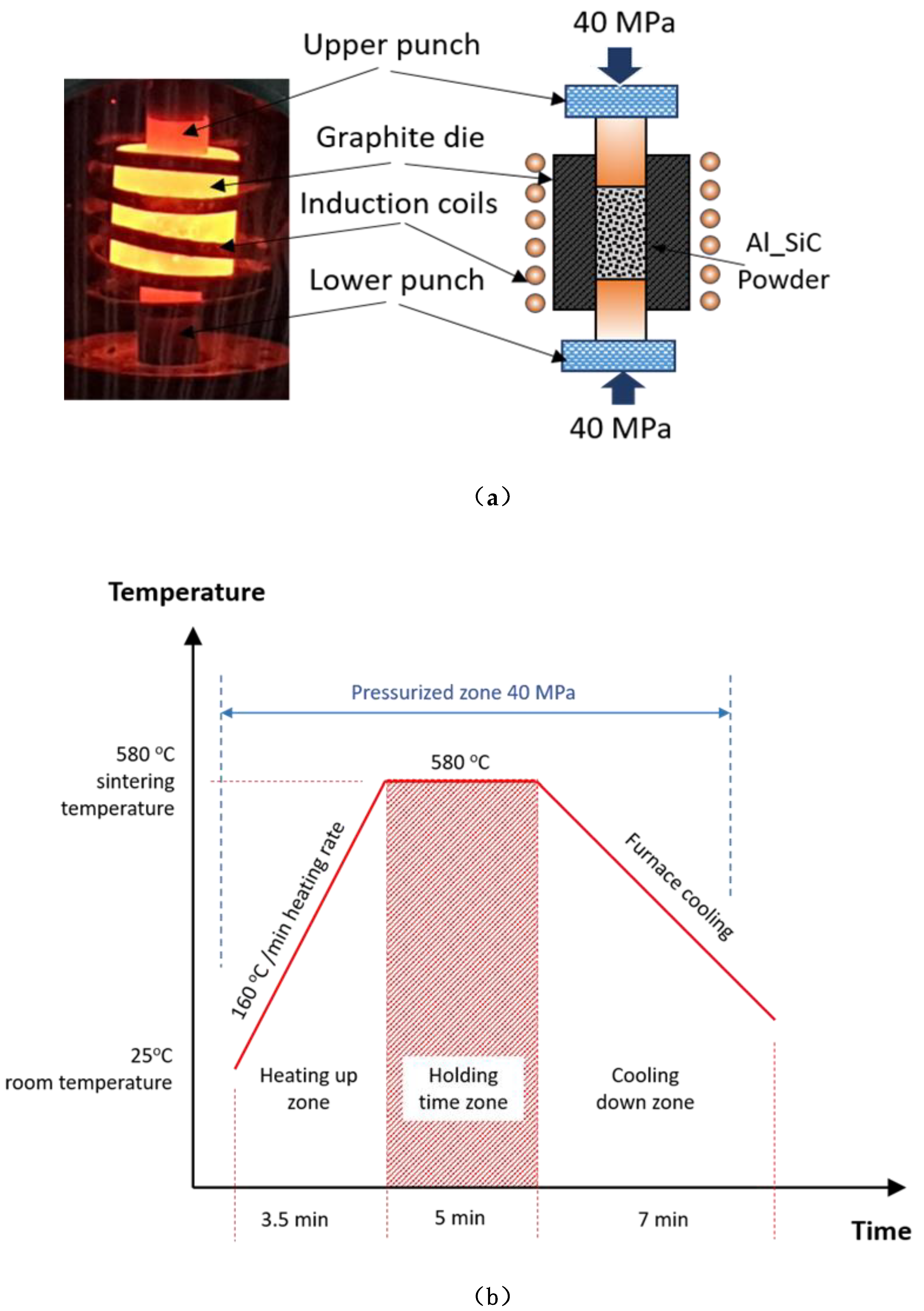
2.3. Consolidation (Sintering)

The 8 wt.% Al/SiC composite powders by LHSBM, LHLSBM, and LHHSBM were then consolidated using an advanced sintering process through a high-frequency induction heat sintering furnace (HFIHS) from ELTek Co., South Korea. The powder mixture was filled into a graphite die (Figure 3a) with 10 mm inner diameter to produce samples with 10 mm diameter and 15 mm height. During 5 min of holding time, the compaction and sintering processes were completed simultaneously at 40 MPa and 580 °C in vacuumed atmosphere. The heating rate during the consolidation process was 160 °C/min while the cooling rate was completed freely as furnace cooling, as shown in Figure 3b. The as-fabricated Al/SiC nano-composites samples were denoted as LHSBM-Al, LHLSBM-Al, and LHHSBM-Al.

2.4. Material Characterization and Testing

To investigate the effect of using different milling scenarios on the produced powder morphology (particle size and shape), the microstructure of LHSBM, LHLSBM, and LHHSBM powders were characterized utilizing field emission scanning electron microscopy (FESEM) Model: JEOL JSM-7600F, Tokyo, Japan. The homogeneity of nano additives distribution was evaluated utilizing energy-dispersive X-ray spectroscopy (EDS). The consolidated Al/SiC nanocomposite samples’ chemical composition was examined using an X-ray diffraction pattern that uses D8 discover from Bruker, Germany, with filtered Cu Kα radiation (λ = 1.5406 Å).
The measurement of density evaluated the physical properties of the Al/Sic nanocomposite samples, ρ E , using Archimedes’ method utilizing Equation (1) [37] and compared with theoretical ones ρ T calculated using Equation (2) according to the ASTM standard test [38]. Then, the voids volume fraction was calculated using Equation (3), where ρalc, ρair, ρ A l , and ρ S i C are the densities of alcohol, air, aluminum powder, and SiC nanoparticles (g/cm3), respectively, and mSair and mSalc are the corresponding nanocomposite masses in air and alcohol (g), respectively. W A l , and W S i C are the weight fractions of Al and SiC in the composite, respectively.
ρ E = ( ρ a l c ρ a i r ) × m S a i r m S a i r m S a l c + ρ a i r ,
ρ T = 1 ( W A l ρ A l + W S i C ρ S i C ) ,
P v ( % ) = ρ T ρ E ρ T .
The mechanical characteristics of Al/SiC nanocomposites were evaluated via Vickers hardness and uniaxial compression test. The composite samples’ hardness was measured after polishing utilizing Vickers hardness tester (WOLPERT UH930, Wilson Hardness, Shanghai, China, with a load ranging from 1 to 250 kgf). The hardness was measured five times for each nanocomposite, and the average was calculated considering the standard error. The samples’ compressive properties were then extracted from the compression test using Instron 5582 Microtester (Instron, University Ave, Norwood, USA) with a strain rate of 10−3/s According to ASTM: E9-89a for the testing procedure and the specimen dimensions.
To investigate the effect of different milling strategies on the produced Al/SiC samples’ tribological properties, a pin-on-disc test apparatus (Figure 4) was utilized in a dry sliding condition for the metal matrix composite samples according to ASTM G99-95 [39]. The pin was represented by the composite sample with dimensions of 10 mm diameter and 15 mm height, while the contact surface was 78.5 mm2, whereas the disk is stainless steel with 20 cm diameter and 13 μm roughness. Each sample was thoroughly polished with fine-grade paper and cleaned with acetone solution, dried by a high-pressure air jet to remove any contaminations before starting each wear test. Moreover, all samples were accurately weighed before and after the wear test using an electronic balance with four-digit accuracy. The wear test was performed for 5, 10, 15, and 20 min per sample using a constant weight of 10 N, with a track diameter of 150 mm and rotational speed of 100 rpm. The experimentation was repeated around five times to ensure repeatability, then both friction coefficient and specific wear rate were calculated with standard error consideration. The recorded mechanical and tribological properties were utilized in constructing a dynamic model for the friction process using the explicit dynamics package of the ANSYS software to investigate the generated stresses on the surface of the Al/SiC composites.
Since the physical contacting bodies do not interpenetrate, the algorithm must establish a relationship between the two contacted surfaces to prevent them from passing through each other in the analysis. For nonlinear solid body contact of faces, Normal Lagrange or Augmented Lagrange formulations can be used. Based on the Ansys software database, the augmented Lagrange method is less sensitive to the magnitude of the contact stiffness. Therefore, in the current investigation, the Normal Lagrange was used where an extra degree of freedom is added to satisfy contact compatibility. Consequently, instead of resolving contact force as contact stiffness and penetration, the contact force is solved explicitly as an extra DOF (where we defined only the applied normal load 10 N in the z-direction). Furthermore, the friction coefficient was fed to the program as a constant value based on the measured values of each specimen.
During both fabrication and experimental testing processes, the composite samples’ surface morphology was observed using FE-SEM to investigate the worn surfaces and explore the wear mechanism.

3. Results and Discussions

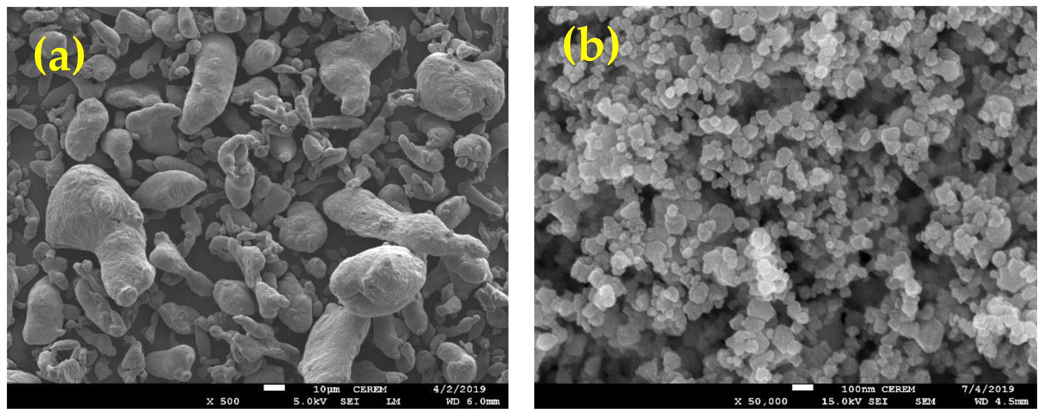
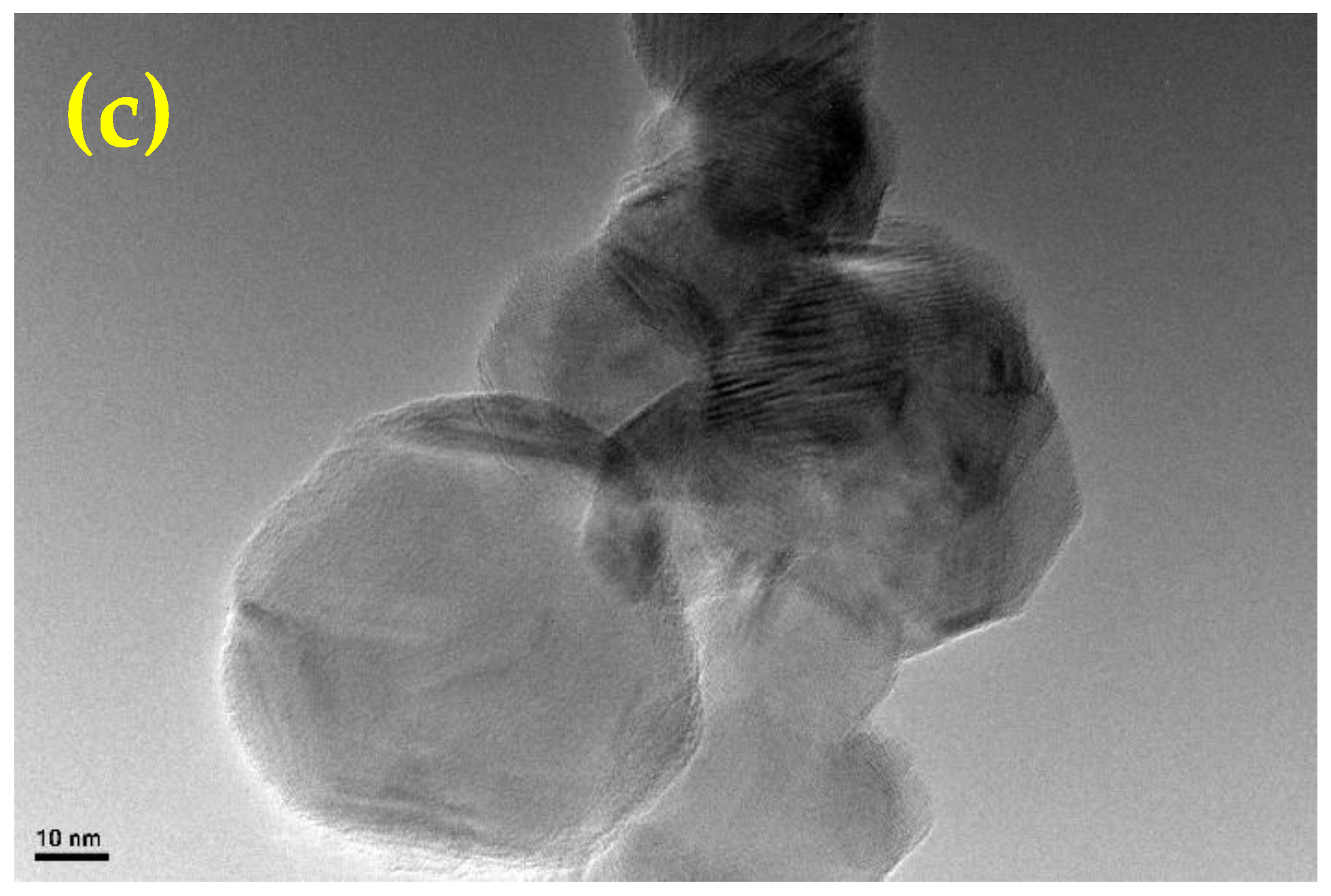
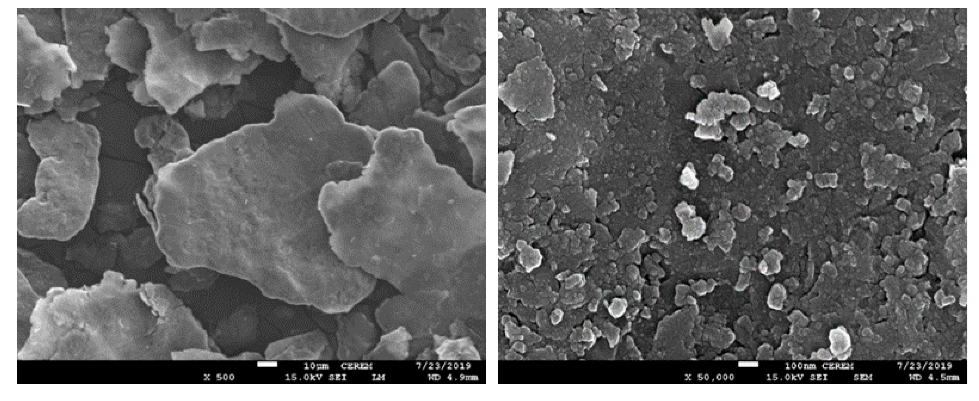
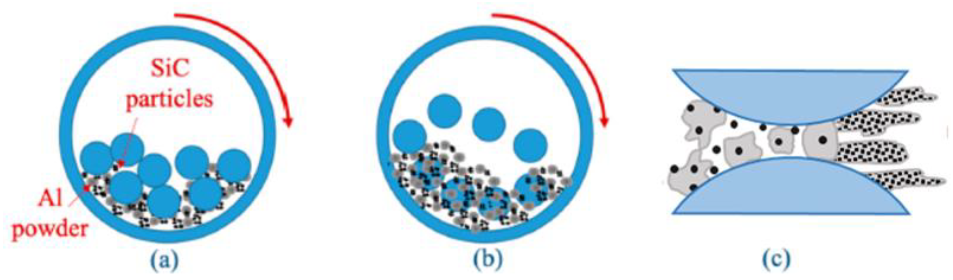
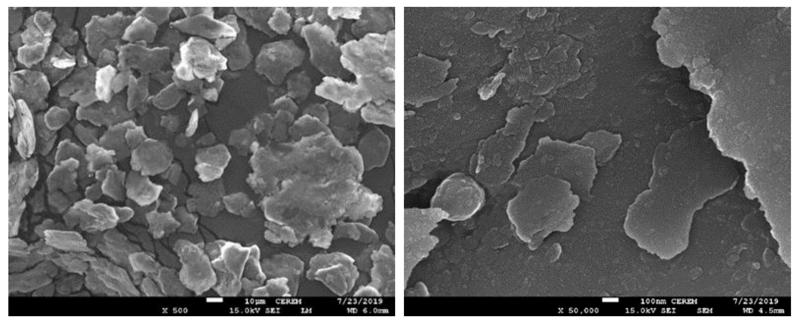
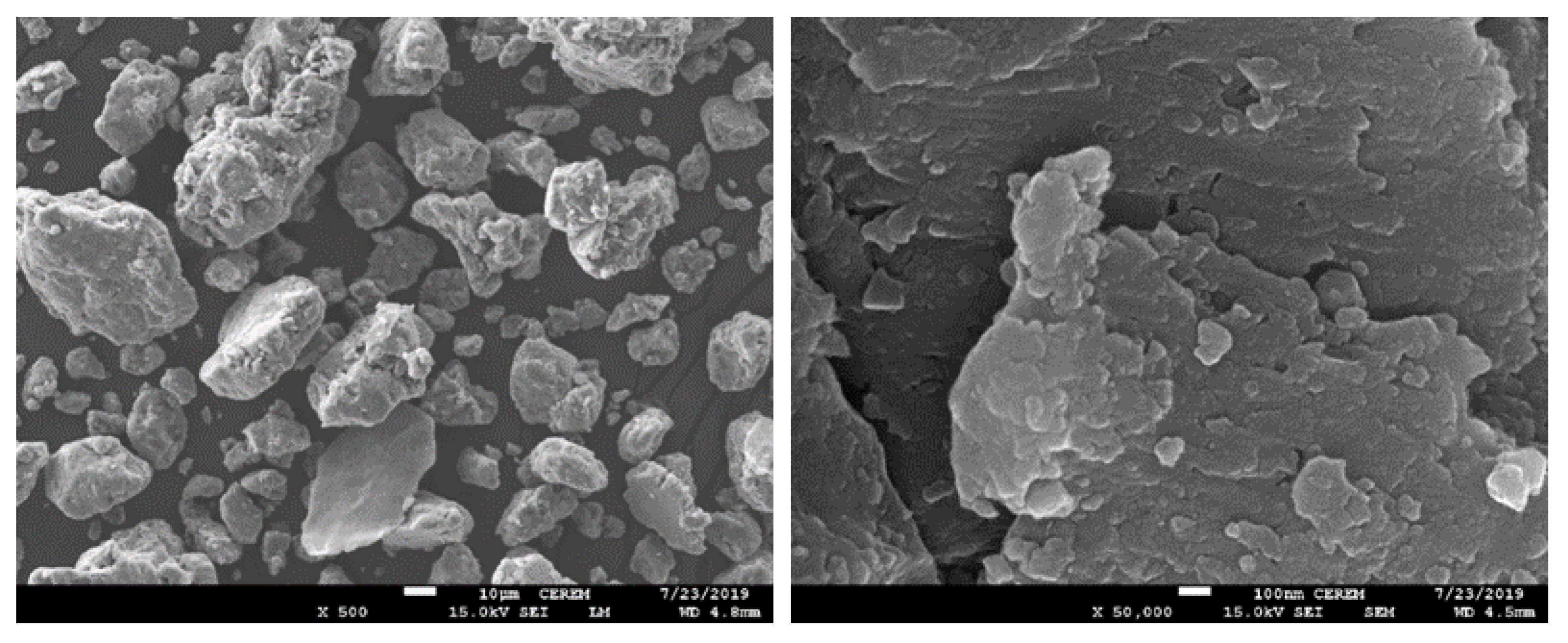
3.1. Ball-Milled Powder Morphology

The morphology of the produced mixed powder and the distribution of the reinforcement into the matrix can affect the different properties of the composites. Consequently, and to understand the effect of different conducted ball-milling scenarios on the morphology of the produced mixed powder, FESEM was used, as shown in Figure 5. Figure 5 represents the first utilized route LHSBM-Al with different scales. It is noticed that most of the produced powder has a flakey shape with uniform size and rough surface. The high surface roughness of the surface of the particles could be attributed to the predomination of fracturing.
Furthermore, it seems that some particles were broken. With a focus on the surface of flake aluminum particles, the broken particles were deposited on its top surface, regarding the distribution of SiC with aluminum matrix, a noticeable agglomeration of the SiC with clusters of few particles which could be attributed to the weak bonding between the aluminum and SiC. Therefore, the dominant deformation performance for the powder is flattening with some fracturing.
The morphology of the produced powder depends on the mechanism of producibility during the ball-milling process. Figure 6a,b describe how the speed and movement of the balls during the ball-milling process affected the powder shape. In the first step, where the speed was low 150 rpm, the shear force generated by balls collisions led to flattening the aluminum particles and distributing SiC nanoparticles. Fan et al. [40] investigated the effect of low speed on the ball-milled powders, and they could prove that low speed can distribute reinforcement uniformly and produce powders with flake shapes. Increasing the speed in the next step to be 300 rpm led to an increase in the compressive force, and consequently, SiC nanoparticles incorporated inside the aluminum flakes; however, Figure 5 shows that the bonding between some SiC and Al is not strong enough. Finally, Figure 6c illustrates that the aluminum flakes were produced with a uniform distribution of the SiC.
In the second scenario, the output mixed powder will be the input for an additional step. Figure 7 illustrates the morphology of aluminum and SiC after applying the third step by downshifting the speed of the ball-milling process to be 150 rpm again, LHLSBM. Minimizing the milling speed at the third step led to a decrease in the compressive force, and the mixed powder return to be subjected to shear force. Consequently, the surface of the flakes becomes smoother as the broken particles are removed from the surface, as shown in Figure 7. Furthermore, the agglomeration of SiC becomes unnoticeable. It is also noticed that the thickness of aluminum flakes has been decreases where the dominant deformation performance for the powder changed from fracturing to be cold welding.
In the third scenario, the output mixed powder of LHSBM will be the input for an additional step where the speed will increase to be 450 rpm, LHHSBM. The morphology of LHHSBM mixed powder is illustrated in Figure 8. The ball-milled powder shape changed from a flakey form to be equiaxed. According to Matori et al. [41], this phenomenon appears when a balance between fracturing and cold welding occurs, and the milled powder attains the steady state. As shown in Figure 8, the milled particles become large because increasing the speed in the third step led to an increase in the compressive force, causing welding between some aluminum flakes. Furthermore, the SiC agglomeration approximately disappeared. Figure 9 shows the mechanism of motion during the ball-milling process with the addition of the third step at high speed.
After the consolidation of the three ball-milled mixed powders, XRD was utilized to investigate the chemical composition of the three Al/SiC composites. Figure 10 illustrates the XRD diffraction peaks for the composite material produced with the three ball-milling scenarios. The peaks of aluminum and SiC are clear, matching with the previous investigation conducted by Almotairy et al. [31]. At 2 thetas, equal to approximately 62 degrees, some peeks appeared at LHSBM and LHHSBM which confirm the presence of Al2O3 generated from the oxidation after the milling process. However, in LHLSBM, the peeks of Al2O3 disappeared because of the third step, where the energy of milling was decreased.

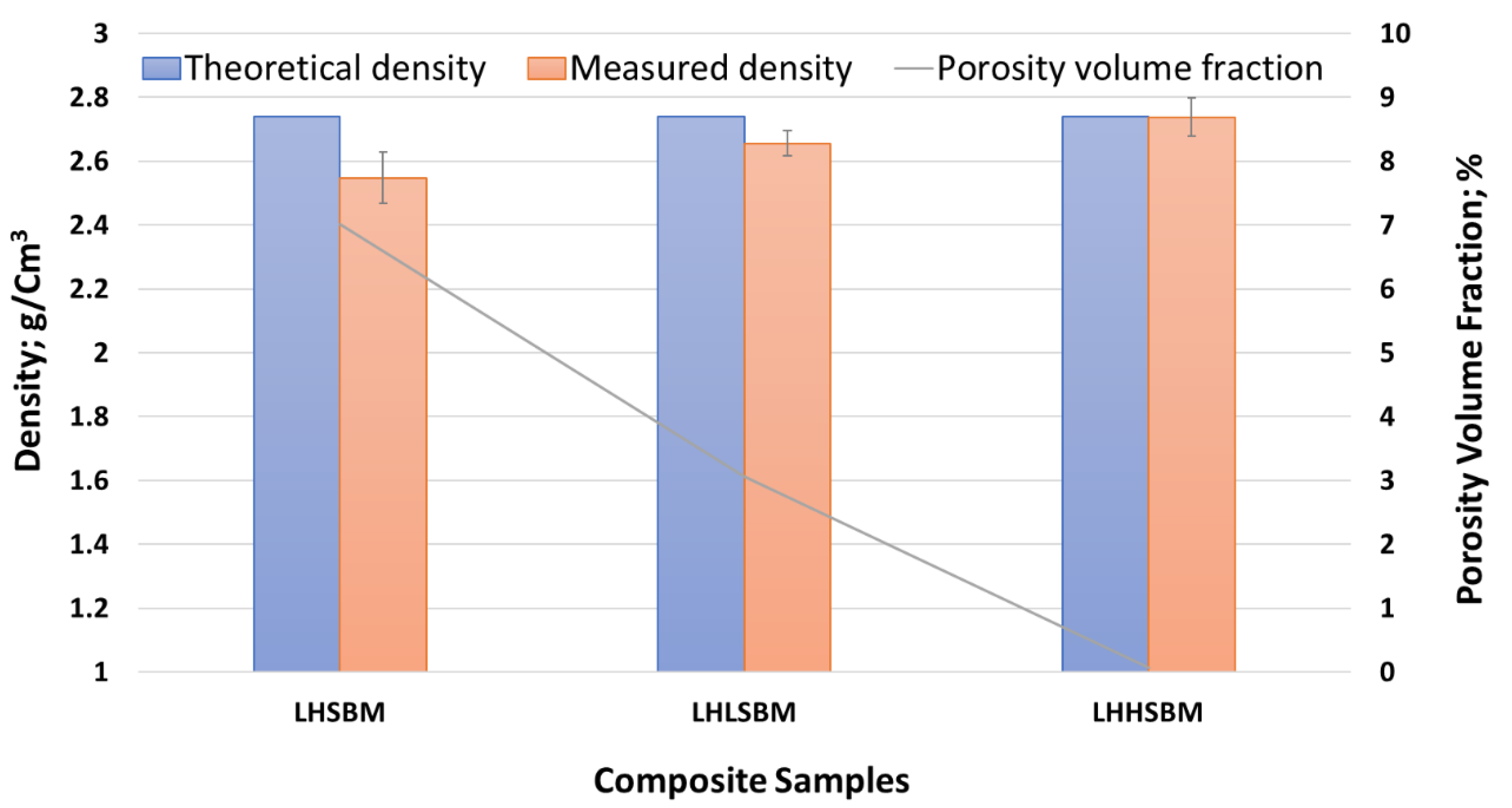
3.2. Physical Properties

The physical properties of composite material can be represented in the measurement of the density of the samples. The density of the composite depends on the ratio of the added reinforcement to the original matrix. Consequently, the densities of the three produced composites were calculated theoretically and compared with their densities that were measured experimentally, as shown in Figure 11 with respect to the production scenario. The results illustrate that the theoretical density for the three samples is the same because it depends on the ratio of the SiC ratio to the aluminum ratio and the density of each one separately, which are the same in the three samples. Regarding the measured densities, a noticeable difference emerged between the three specimens. The discrepancy in density among the three produced samples could be attributed to the formation of pores and voids during the consolidation process and the morphology of the produced powders. Consequently, the porosity volume fraction was calculated and illustrated in the same figure.
The density of the LHSBM sample seems to be relatively low compared with the other two samples. The decrease in the LHSBM sample could be attributed to the low milling time, which produces large flake particles with a high surface roughness that increases the porosity volume fraction and decreases the densification rate [5] to the other samples. On the other hand, the LHHSBM sample shows a very mall difference between the theoretical and experimental measured density, emphasizing the effectiveness of utilizing the LHHSBM scenario in achieving a complete dense Al/SiC composite.

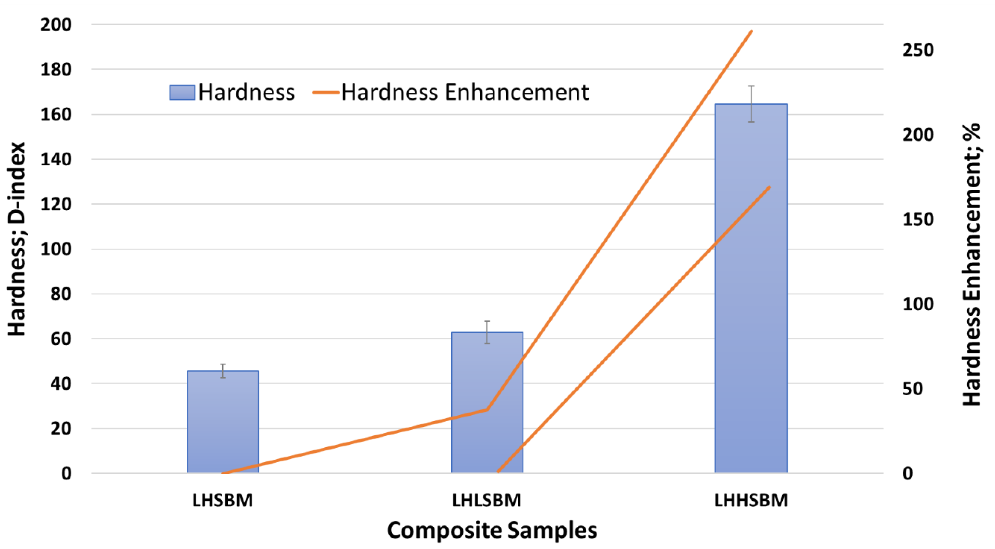
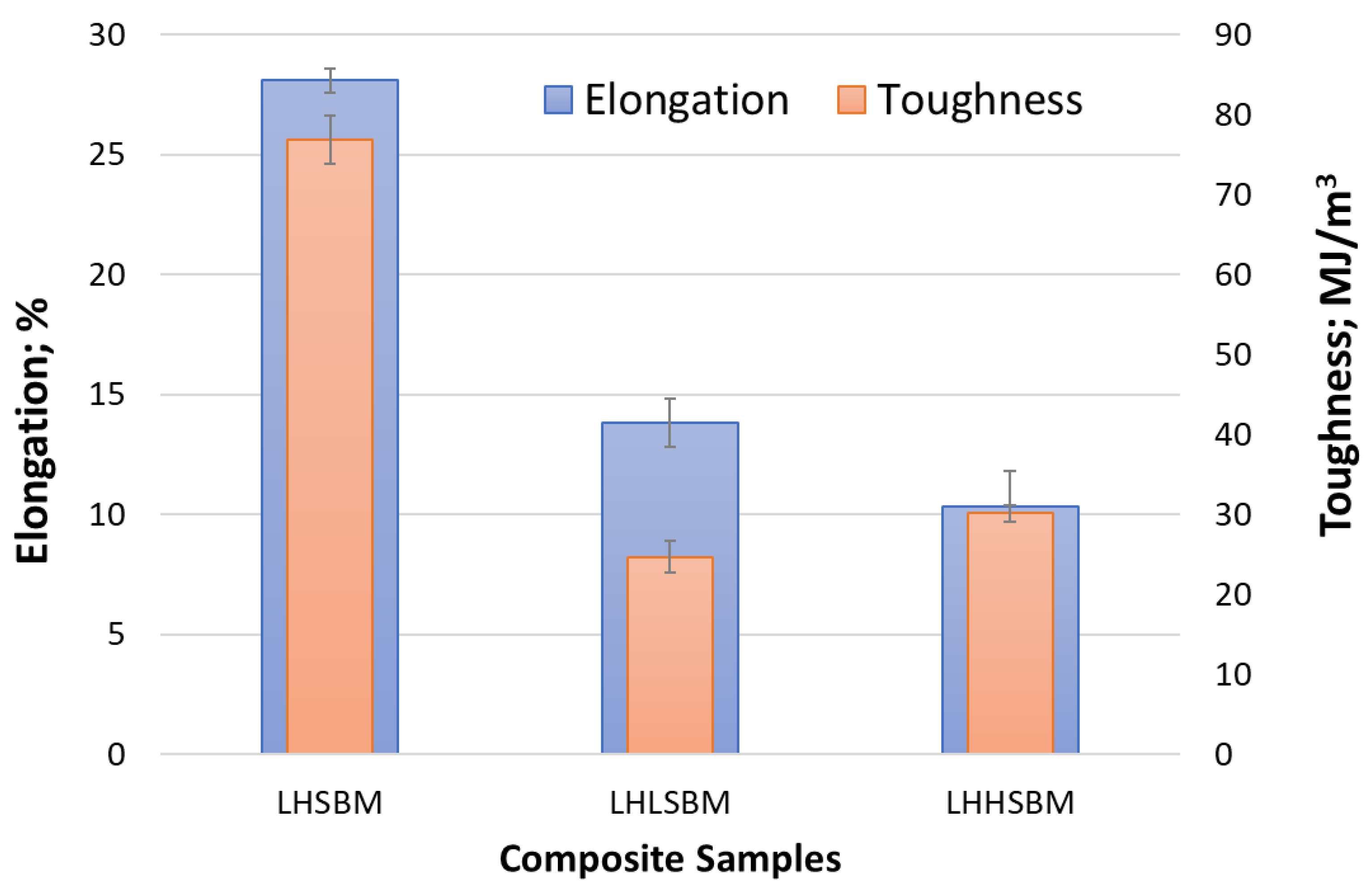
3.3. Mechanical Properties

The Mechanical characteristics of metal matrix composites usually depend on various variables, including bonding between composite elements, micro-nano-structure, parameters of consolidation, and others [42]. Figure 12 illustrates the variation in the hardness for the three aluminum/SiC composite samples. The samples microhardness for LHSBM, LHLSBM, and LHHSBM were 44.5, 63.2, and 165.2, respectively. The results show that utilizing different scenarios of ball milling, based on the steps and speeds, could have a different effect on the hardness of the produced samples even if they have the same percentage of reinforcement additives. LHSBM recorded the lowest hardness value, and this result could be attributed to the low time of ball milling compared to the other two utilized scenarios.
On the contrary, LHHSBM hardness recorded an enhancement in the hardness, which reach 260% and 160% relative to LHSBM, and LHLSBM, respectively. The enhancement in the LHHSBM harness could be attributed to the high energy acquired from the increase in the compressive force due to increasing the speed in the last step, which decreases the residual dislocation and strengthens the interfacial bonding between the aluminum and SiC. Moreover, utilizing LHHSBM yields enhancement in the hardness because of the effective load transfer from the aluminum matrix to the SiC hard particle, which can be evidence of the uniform distribution of SiC inside the aluminum matix strong bonding between them. LHLSBM recorded a moderate hardness with an enhancement of 39% relative to LHSBM. Although the speed in the third step decreased, increasing the ball-milling time led to an increase in the hardness, which is in accordance with Abd-Elwahed et al. [43].
To investigate the effect of utilizing different ball-milling scenarios on the load-carrying capacity, the three Al/SiC samples were compressed. The compression properties were measures, as shown in Figure 13 and Figure 14. Figure 13 illustrates the average Young’s modulus and compressive yield strength concerning the three composite samples produced by different ball-milling scenarios. Figure 14 shows the average elongation and toughness with respect to the same three composite samples.
The compressive properties of LHSBM, LHLSBM, and LHHSBM Al/SiC composites were the same as usual results of ball-milling processes, which states that the consolidated materials acquires high strength low elasticity as a result of increasing the energy of the milling process [9,10]. Therefore, the LHHSBM sample recorded the highest Young’s modulus and compressive yield strength with 11 GPa and 500 MPa, respectively. The enhancement in Young’s modulus and compressive yield strength of the LHHSBM sample relative to the LHSBM sample reached 209.7% and 201.6%, respectively, and for the LHLSBM sample was 141% and 159.5%, respectively. The LHLSBM sample also recorded an enhancement in Yong’s modulus and yield strength relative to LHSBM with 25.5% and 16.2%, respectively. These enhancements in LHLSBM and LHHSBM samples relative to the LHSBM sample could be attributed to the additional step of milling and for the mechanism of powder deformation.
In ball milling, the dominant factor affecting the mechanism of powder deformation is the force resulting from the frequency of collision balls. As mentioned in the ball-milled powder morphology subsection, the collision force could be classified into shearing and compressive forces [44,45]. The shear force resulting from balls friction and rolling could effectively disperse the nanoparticles among the matrix particles [46]. However, the compressive force is considered an efficient way to deform the powder to be flattened, and the prolonged time contributes to cold welding. Increasing the milling speed would increase both types of forces but with different growth rates [32]. The steps of producing the LHHSBM sample can help in understanding the unprecedented improvement in the mechanical properties. The first scenario of ball-milling LHSBM is the input of the third scenario, LHHSBM. Therefore, the powder was subjected to a low milling speed of 150 rpm, which uniformly distributed the SiC nanoparticles into the aluminum matrix, and aluminum powder evolved into a flake shape. Then, the speed was doubled to be 300 rpm, which increased the compressive force relative to the shear force and laminate the broken aluminum particles with the appearance of some clusters. However, the shear force was enough to distribute the SiC uniformly on the aluminum flakes. Finally, the mixed powder was subjected to a higher speed 450 rpm that significantly increased the compressive force, enhancing the bonding strength between the aluminum and SiC. Moreover, with prolonged time, aluminum flakes began to be subjected to cold welding, enhancing inter-flake bonding. Consequently, a simultaneous enhancement of the strength in the in situ LHHSBM Al/SiC composite. To summarize the compression results, the LHHSBM SiC composite sample exhibited the highest strength, but twice and triple times less than LHSBM SiC composite sample in elongation and toughness. This degradation in elongation and toughness is due to the high energy acquired during the last step of milling [47].

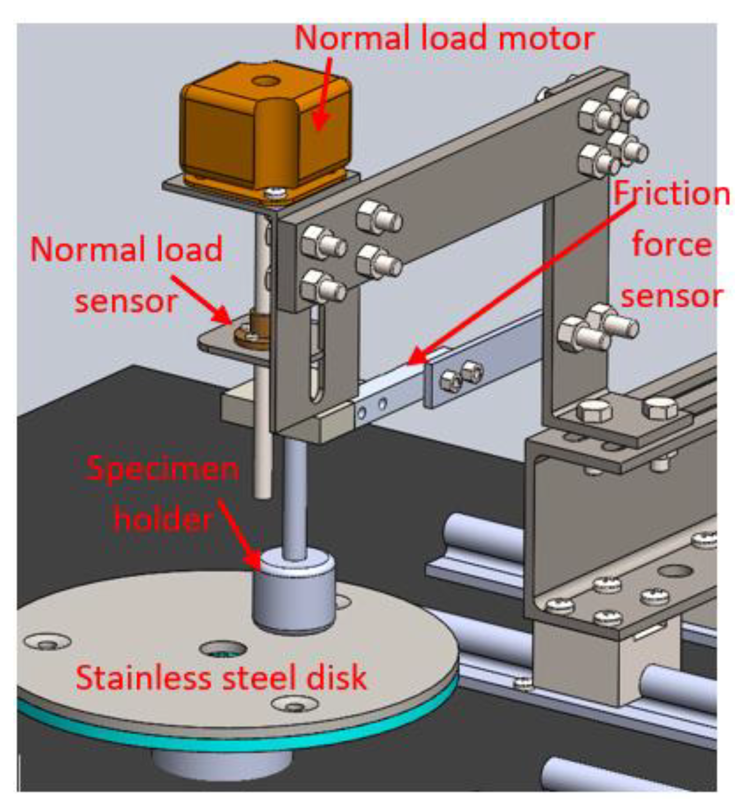
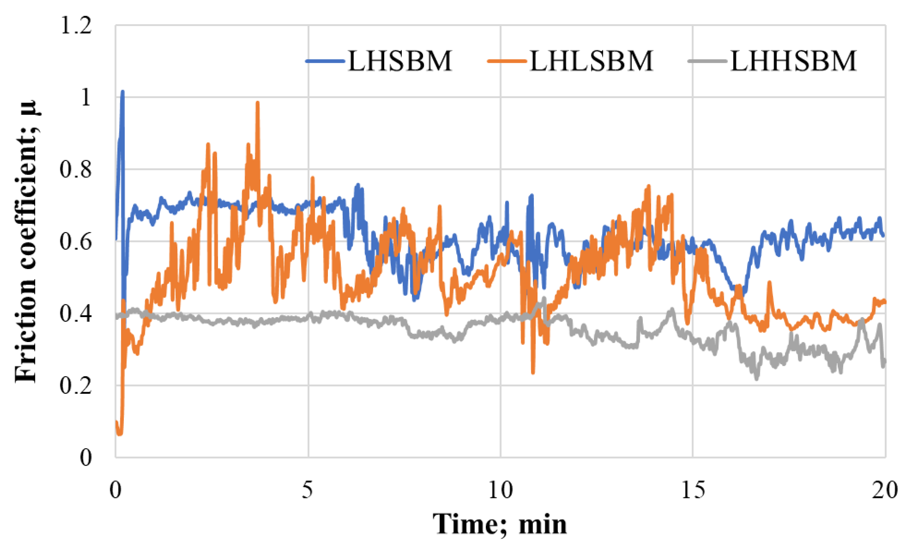
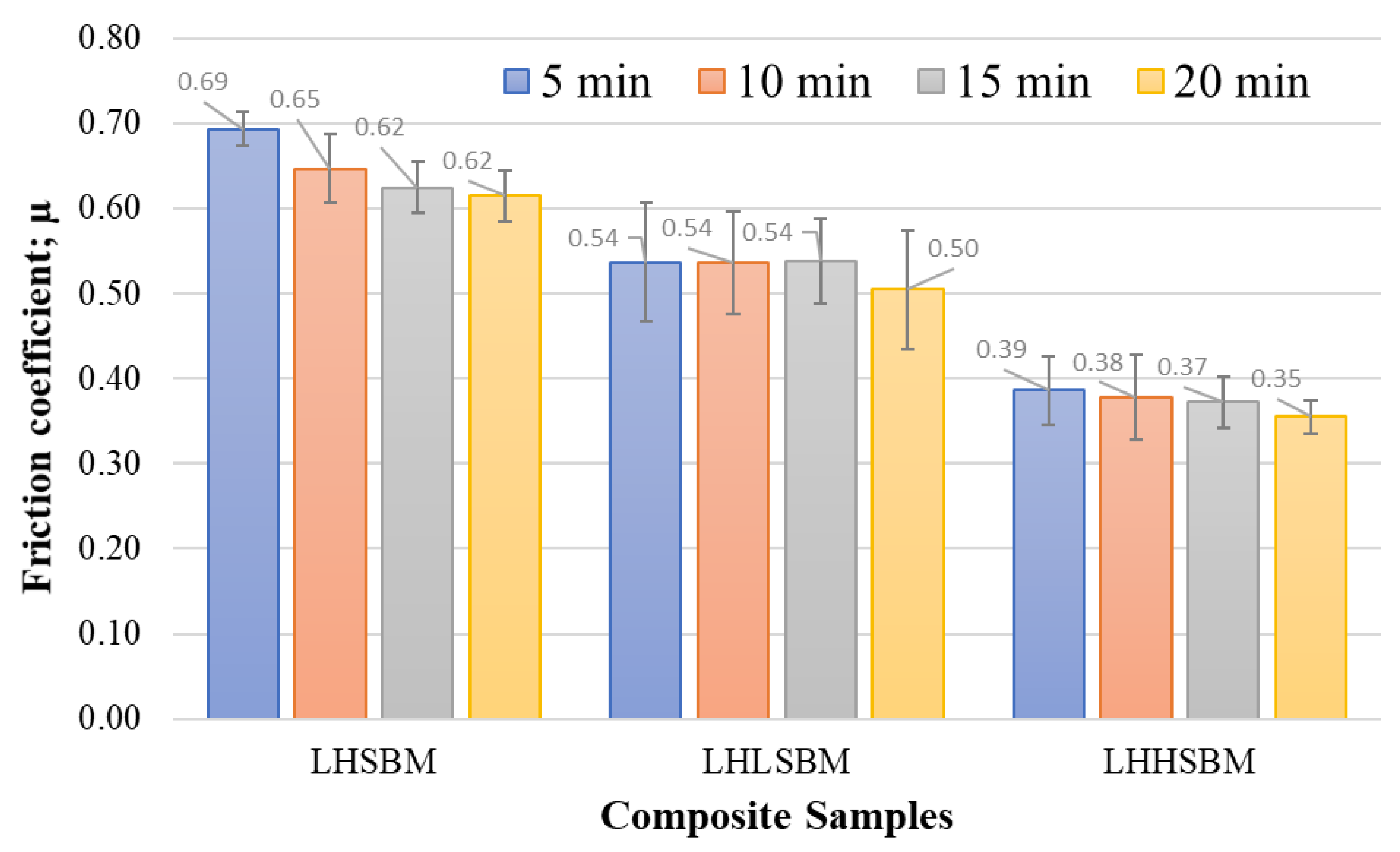
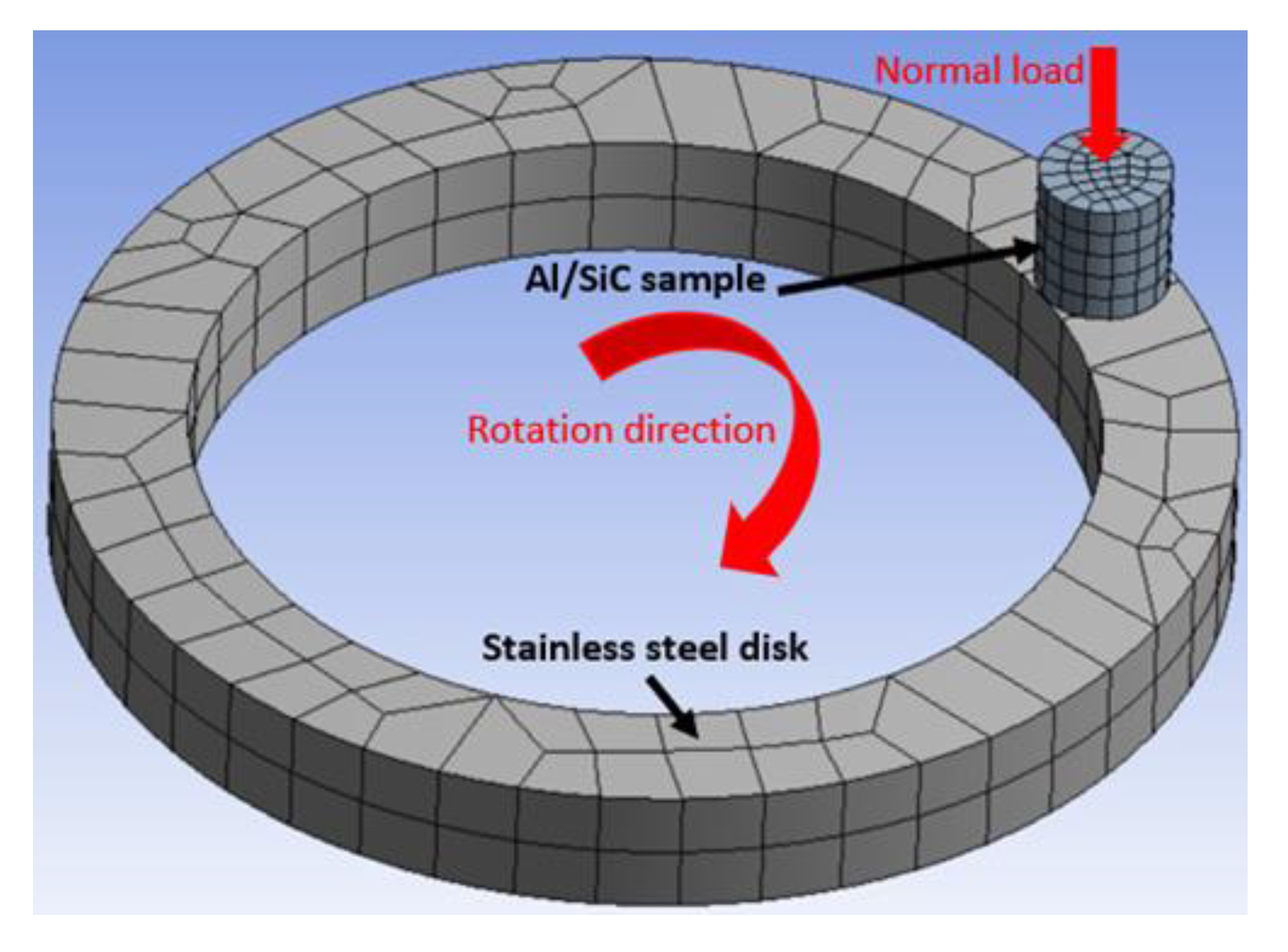
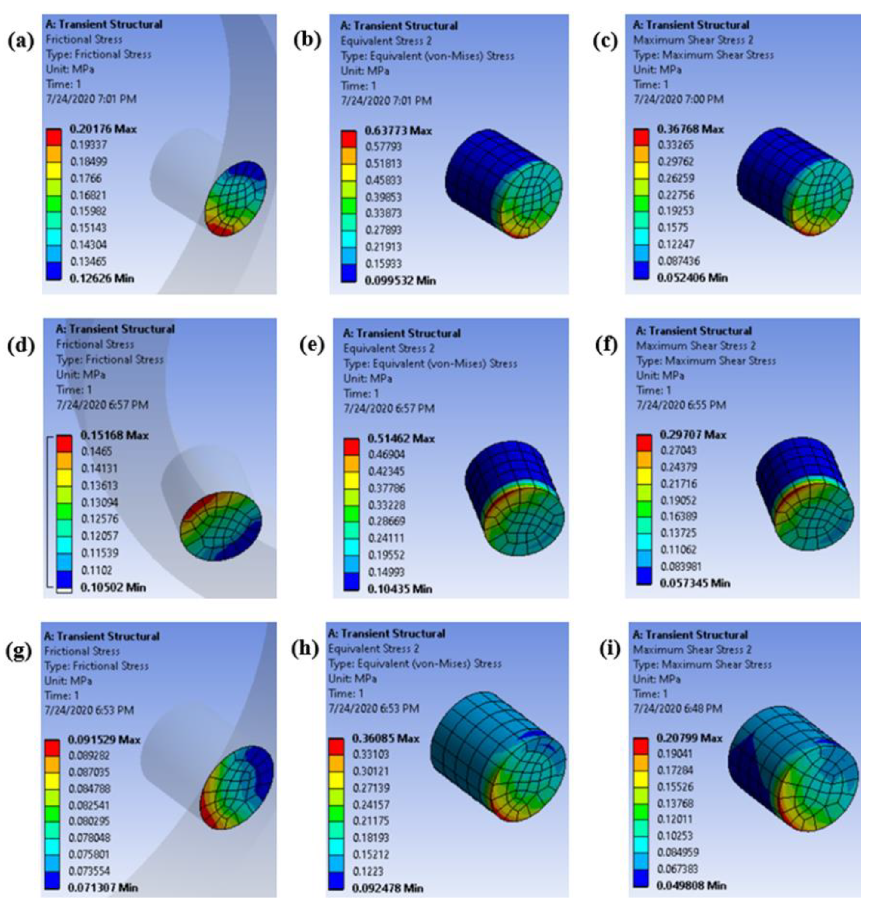
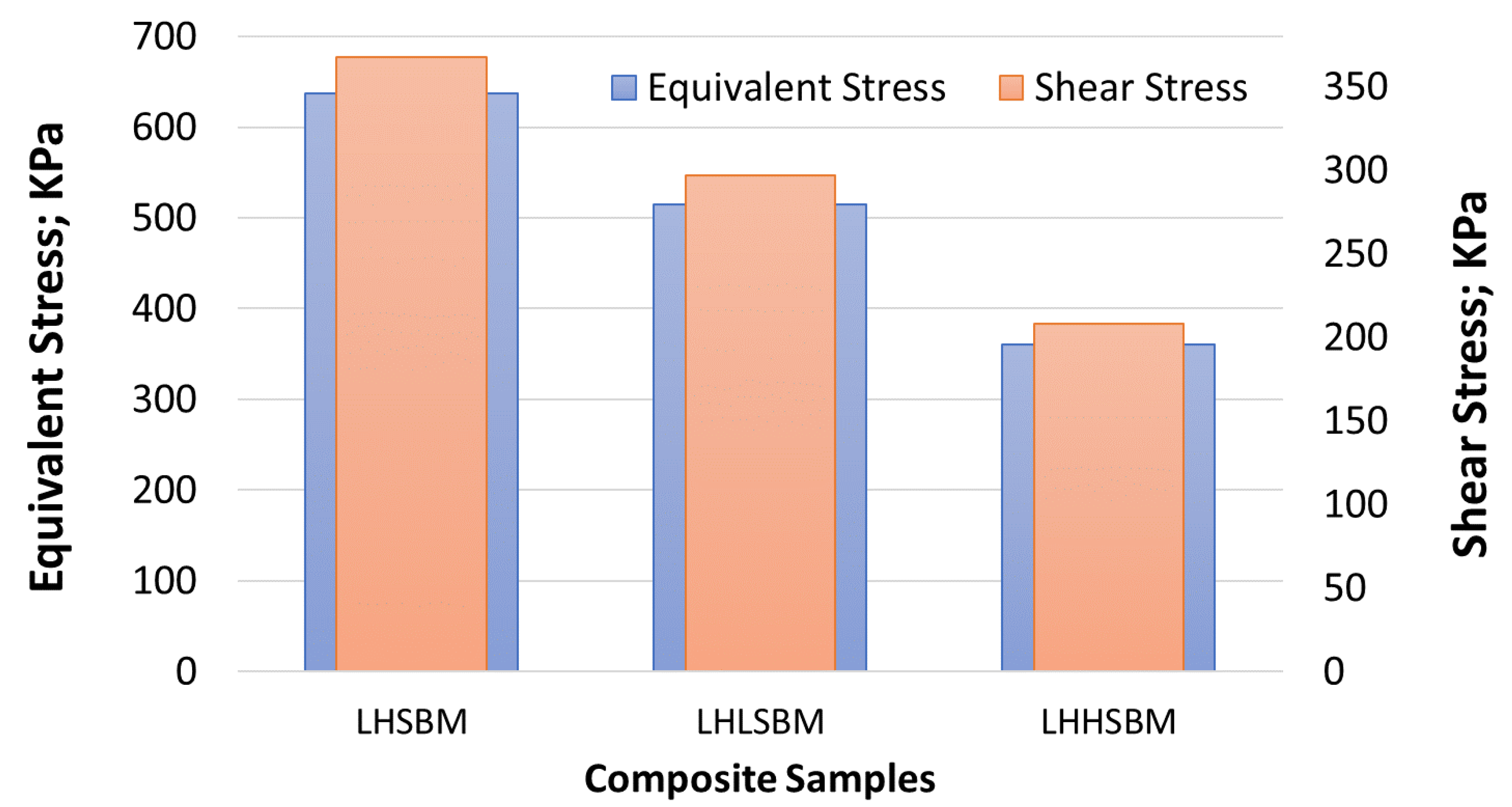
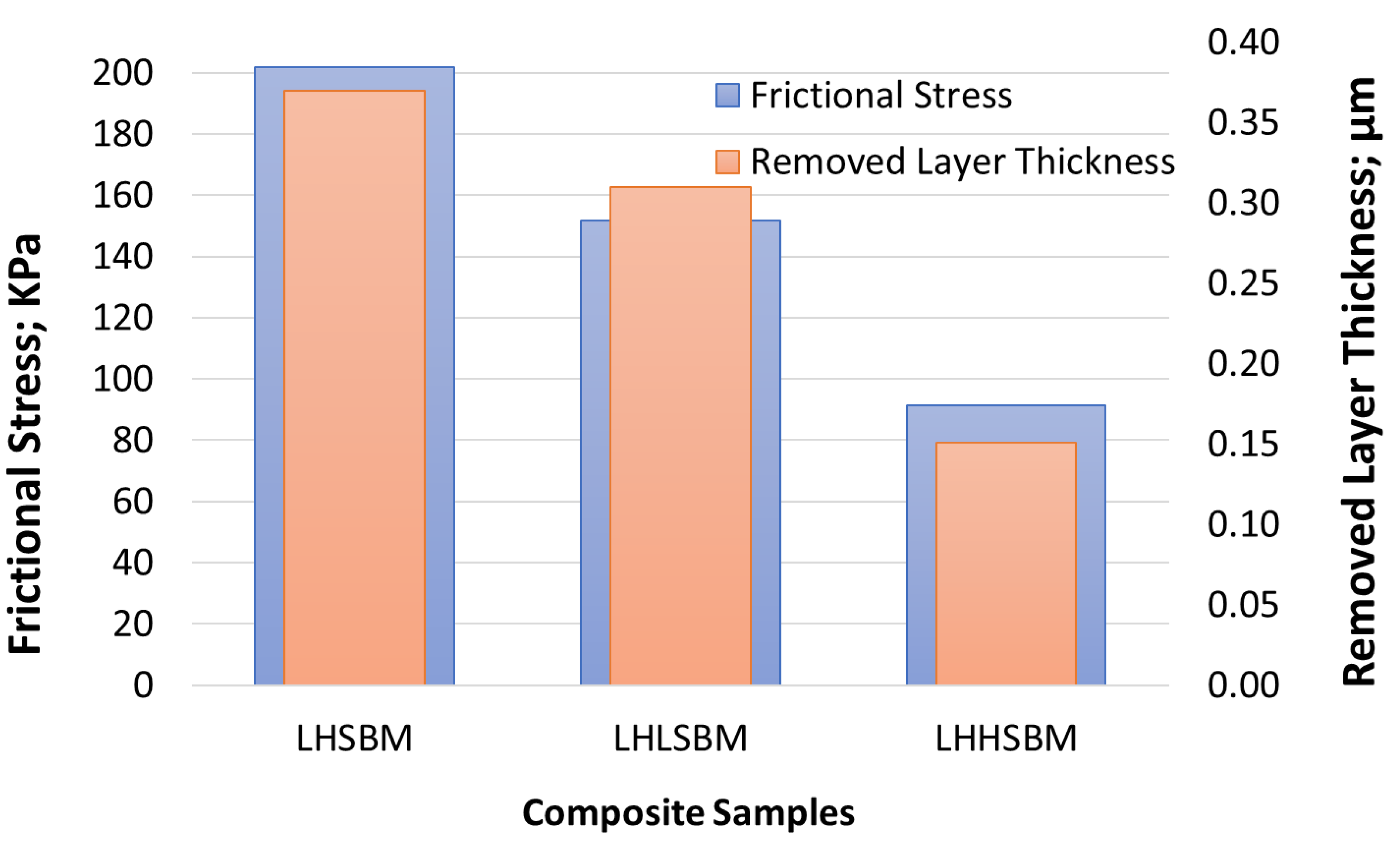
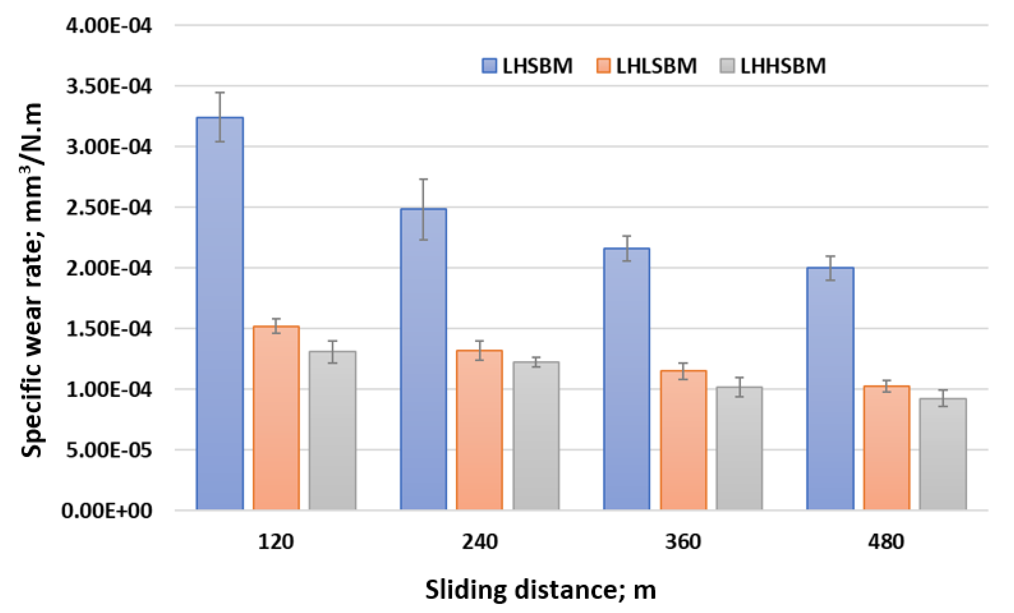
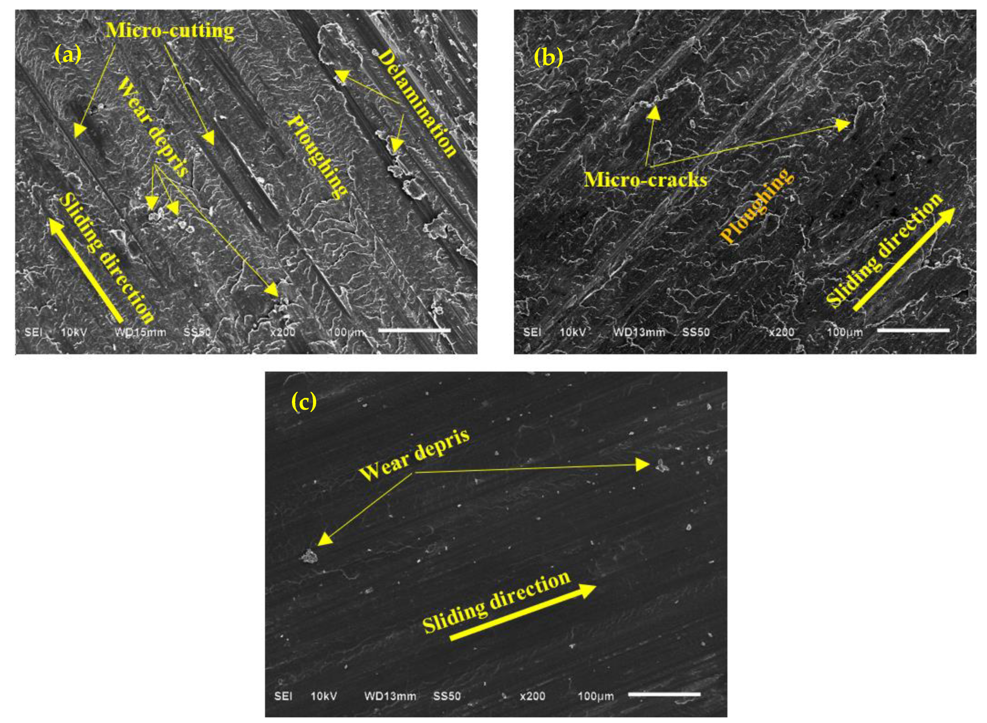
3.4. Tribological Properties

To recognize how the sample preparation technique (different ball-milling scenarios) can affect the friction coefficient of Al/SiC nanocomposite, the three SiC samples were rubbed under a constant load of 10 N against a stainless-steel disk with a speed of 100 rpm. Figure 15 shows the real-time variation of the friction coefficient for the three Al/SiC samples for 20 min. It is observed that the friction coefficient decreases with the increase in time for all the fabricated specimens. Furthermore, LHHSBM recorded the lowest friction coefficient with the change of time. However, LHSBM and LHLSBM results overlap with a slight increase in the values of the friction coefficient in LHSBM.
For more understanding of the effect of sliding time on the friction coefficient of the Al/SiC samples, the tribological experiments were repeated for different sliding times 5, 10, 15, and 20 min, and the average friction coefficients were estimated considering the standard errors, as shown in Figure 16. It is evident that increasing the sliding period led to a decrease in the coefficient of friction. The noticeable reduction in the friction coefficient for the three samples with increasing the friction period could be attributed to the smoothness on the Al/SiC surface due to the rubbing against the stainless-steel disk for a long sling time. Nevertheless, the tribological characteristics for the Al/SiC samples remain the same; LHHSBM recorded the lowest friction coefficient relative to LHSBM and LHLSBM. The decrease in friction coefficient can denote an improvement in the load-carrying capacity [14], which can be evaluated according to the stress distribution between the contact surfaces, AL/SiC samples, and stainless-steel disk.
To explore the load-carrying capacity for the three Al/SiC samples, a 3D finite element model (FEM) was constructed utilizing the explicit dynamics package of the ANSYS software that represents the friction experiment, as shown in Figure 17. The FEM was constructed in two main parts; first, a hollow disk with an outer diameter of 160 mm and inner diameter of 140 mm represents the stainless-steel disk. Second, a cylindrical pin with a diameter of 10 mm and a height of 13 mm represents the Al/SiC composite sample. Both the disk and the bin were meshed utilizing hexahedron and tetrahedron, automatic mesh.
Mesh size selection has been optimized during this work, starting by a very fine size up to the largest possible size. The final conclusion was that even the mesh was refined, the results are approximately the same with a negligible difference. Consequently, and to save the solution time, mesh size was selected based on the automatic mech offered by the software itself.
According to the experimentally measured values, the mechanical properties of the three Al/SiC were fed to the ANSYS software. The measured friction coefficients were defined between the contact surface in order to measure the different generated stresses resultant from the rubbing process.
The boundary conditions were added accurately as follows:
  • The stainless-steel disk rotates with a constant speed of 100 rpm clockwise.
  • The pin, Al/SiC composite, was fixed in the x-y plane and free in the z-direction.
  • A load of 10 N was applied on the surface of the pin in the z-direction, which can push the pin towards the hollow disk.
  • The contact between the pin and the hollow disk was recognized as frictional.
Figure 18 illustrates the different stresses generated from the friction between the three Al/SiC composite samples and the stainless-steel disk. As shown in the figure, the motion direction of the stainless-steel disk resulted in concentrated stress on the edge of the composite samples for all cases. Utilizing the LHHSBM scenario in producing the Al/SiC composite sample led to a reduction in the maximum equivalent stress generated on the surface of the composite, as shown in Figure 19. This decrease in the maximum equivalent stress resulted from improved composite strength due to the utilization of the LHHSBM technique. Therefore, the load-carrying capacity growing properly in which a decrease in the friction coefficient has been achieved [48]. On the other hand, Figure 19 recorded a reduction in the shear stress generated on the surface of the Al/SiC sample produced by LHHSBM relative to the other two samples, resulting in the recorded drop in the friction coefficient [49].
Figure 20 illustrates the frictional stress and the thickness of the wear layer during the friction process for the three Al/SiC composites. LHHSBM sample recorded the lowest frictional stress and shear stress; consequently, it is predictable that the wear rate in the LHHSBM sample will be lower than the other two composite samples. To investigate the wear that occurred in the three Al/SiC samples, the specific wear rate was calculated for each sample after rubbing for different sliding distances 120, 240, 360, and 480 m, as shown in Figure 21. As expected from the finite element analysis, the LHHSBM sample recorded the lowest specific wear rate compared with LHSBM and LHLSBM samples at different sliding distances. These results could be attributed to the enhancement archived in the mechanical characteristics for the LHHSBM technique, which showed that utilizing the LHHSBM scenario improved the strength of the produced composite. As illustrated in the powder morphology subsection, utilizing LHHSBM enhanced the bonding strength between the aluminum and SiC, which prohibited the degradation of the Al/Sic during the frictional process and consequently improved the wear resistance. Moreover, the finite element analysis showed a reduction in the shear stress on the LHHSBM Sample surface, reducing the wear rate. In LHSBM composite sample, the weak bond between the aluminum and SiC led to the escape of some SiC nanoparticles from the aluminum matrix during the sliding process. These SiC nanoparticles worked as abrasive particles to the Al/SiC composite sample; consequently, the specific wear rate increased [50]. In summary, there is an agreement between experimental and finite element analysis results that prove the effectiveness of utilizing LHHSBM in Al/SiC composite production.
For more clarification of the wear characteristics of the Al/SiC composite produced with three different ball-milling scenarios, the worn surfaces were analyzed utilizing a scan electron microscope (SEM), as shown in Figure 22. Figure 22a illustrates the worn surface of the LHSBM sample. Obviously, the worn surface is ploughed. Some particles were escaped from the matrix that acted as debris—furthermore, a degradation in the surface due to micro cutting causes some delamination regions. An increase in the specific wear rate occurred due to the surface degradation, and the delaminated areas increase the shear resistance in which the friction coefficient raised. The kind of wear, in this case, could be a merge between abrasive and delamination mechanism.
Figure 22b illustrates an initiation of the LHLSBM composite sample surface to be damaged and a microcracks propagation. The delaminated areas and the micro-plowing decreased compared with the surface of the LHSBM sample due to the enhancement in the mechanical properties after utilizing the LHLSBM scenario. The wear mechanism in the LHLSBM was converted to be a fatigue mechanism. Utilizing the third ball-milling scenario (LHHSBM) led to an enhancement in the hardness and the strength of bonding (interfacial adhesion) between the aluminum matrix and the SiC nanoparticles. Consequently, the stresses generated on the sample surface could transfer among the composite components leading to an enhancement in the wear resistance. The SEM analysis of the surface shows a smoothness with unnoticeable cracks, micro-plowing, and a little bit of wear debris, as shown in Figure 22c.

4. Conclusions

This investigation experimentally evaluates the evolution of utilizing different high-energy ball-milling techniques on the mechanical and tribological properties of Al/SiC composite. Three different ball-milling scenarios were used based on the milling step number and milling speed. The output powders morphology for each milling scenario was studied, and the mechanisms of production were illustrated. Through comparative investigation of the low–high-speed ball milling (LHSBM), low–high–low-speed ball milling (LHLSBM), and low–high–high-speed ball milling (LHHSBM), the following conclusions can be drawn:
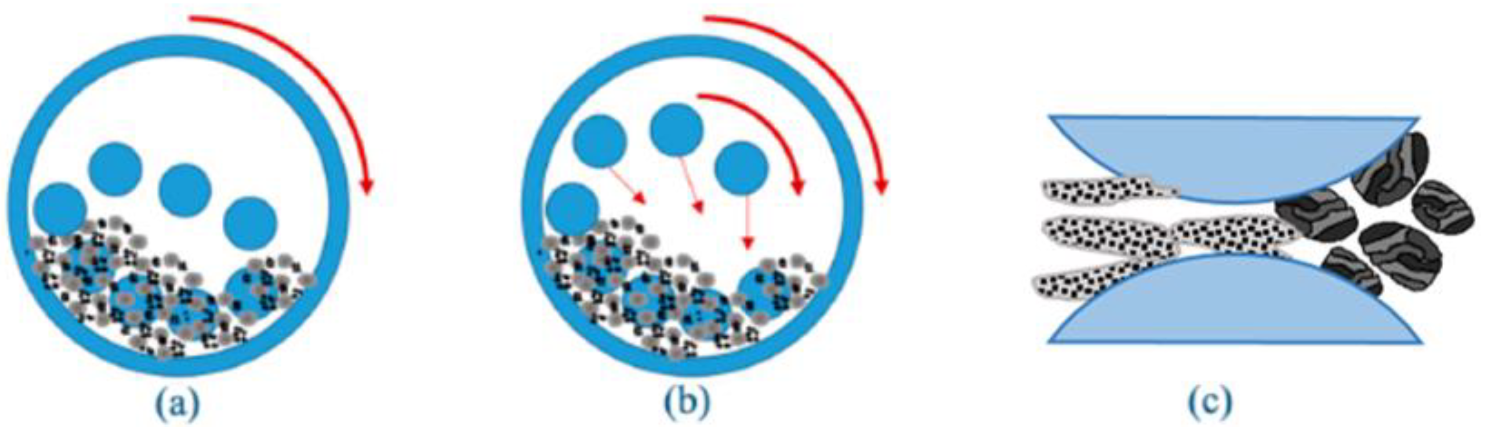
The two speeds ball-milling scenario (LHSBM) was considered on the basis of which the comparison is made. The mechanism of utilizing such a scenario was uniform dispersion of SiC and deformation of aluminum powder into flakes with a rough surface and insufficient bonding between the aluminum and SiC. The mechanical and tribological results of this milling scenario were considered the base in which the other results were compared.
Regarding the second ball-milling scenario (LHLSBM), the flake particles became smooth with fewer broken particles due to the increasing shearing force compared with the compressive force during the milling process. Consequently, a slight enhancement in the mechanical and tribological properties was achieved relative to LHSBM.
In the last ball-milling scenario (LHHSBM), a balance between interfacial bonding, regular dispersion, and structural integrity for the SiC and aluminum particles. Therefore, improvement in Young’s modulus, compressive yield strength and hardness by 209.7%, 201.6%, and 260%, respectively, relative to LHSBM. Furthermore, the wear resistance increased by approximately 147.5% relative to LHSBM. An agreement between experimental and finite element analysis results proves the effectiveness of utilizing LHHSBM in Al/SiC composite production compared with other scenarios.

Author Contributions

Conceptualization, A.F., H.F.A. and H.S.A.; methodology, A.F., S.M.A. and H.S.A.; software, A.F. and M.O.A.; validation, S.M.A., M.O.A. and H.F.A.; investigation, A.F., S.M.A., M.O.A., H.F.A. and H.S.A.; resources, H.F.A.; writing—original draft preparation, A.F., M.O.A. and H.S.A.; writing—review and editing, A.F. and H.S.A.; supervision, H.F.A.; funding acquisition, H.F.A. All authors have read and agreed to the published version of the manuscript.

Funding

This research was funded by the Deanship of Scientific research at King Saud—Research Group no. RGP-1440-101.

Acknowledgments

The authors like to extend their appreciation to the Deanship of Scientific research at King Saud University for funding this work through the Research Group no. RGP-1440-101.

Conflicts of Interest

The authors declare no conflict of interest.

References

  1. Rocha, R.M.; Bressiani, J.C.; Bressiani, A.H.A. Ceramic substrates of β-SiC/SiAlON composite from preceramic polymers and Al–Si fillers. Ceram. Int. 2014, 40, 13929. [Google Scholar] [CrossRef]
  2. Karl, U.K. Metal matrix composites: Custom-made materials for automotive and aerospace engineering. In Basics of Metal Matrix Composites; Wiley-VCH: Weinheim, Germany, 2006. [Google Scholar] [CrossRef]
  3. Ibrahim, A.M.M.; Shi, X.; Radwan, A.R.; Mohamed, A.F.A.; Ezzat, M.F. Enhancing the tribological properties of NiAl based nano-composites for aerospace bearing applications. Mater. Res. Express 2019, 6, 085067. [Google Scholar] [CrossRef]
  4. Ibrahim, A.M.M.; Mohamed, A.F.A.; Fathelbab, A.M.; Essa, F.A. Enhancing the tribological performance of epoxy composites utilizing carbon nano fibers additives for journal bearings. Mater. Res. Express 2018, 6, 035307. [Google Scholar] [CrossRef]
  5. Adebisi, A.A.; Maleque, M.A.; Rahman, M.M. Metal matrix composite brake rotor: Historical development and product life cycle analysis. Int. J. Automot. Mech. Eng. 2011, 4, 471–480. [Google Scholar] [CrossRef]
  6. Metal Matrix Composite Market Is Forecasted to Grow at a Rate of 6.0% by 2027| Reports and Data, GlobeNewswire News Room, 8 June 2020. Available online: https://www.globenewswire.com/news-release/2020/06/08/2045231/0/en/Metal-Matrix-Composite-Market-is-forecasted-to-grow-at-a-rate-of-6-0-by-2027-Reports-and-Data.html (accessed on 23 April 2021).
  7. Metal Matrix Composite Market Size Report, 2020–2027. Available online: https://www.grandviewresearch.com/industry-analysis/metal-matrix-composites-mmc-market (accessed on 23 April 2021).
  8. Mortensen, A.; Jin, I. Solidification processing of metal matrix composites. Int. Mater. Rev. 1992, 37, 101–128. [Google Scholar] [CrossRef]
  9. Aussavy, D.; Costil, S.; el Kedim, O.; Montavon, G.; Bonnot, A.-F. Metal Matrix Composite Coatings Manufactured by Thermal Spraying: Influence of the Powder Preparation on the Coating Properties. J. Therm. Spray Technol. 2014, 23, 190–196. [Google Scholar] [CrossRef]
  10. Biswal, H.J.; Vundavilli, P.R.; Gupta, A. Perspective—Electrodeposition of Graphene Reinforced Metal Matrix Composites for Enhanced Mechanical and Physical Properties: A Review. J. Electrochem. Soc. 2020, 167, 146501. [Google Scholar] [CrossRef]
  11. Zakaria, H.M. Microstructural and corrosion behavior of Al/SiC metal matrix composites. Ain Shams Eng. J. 2014, 5, 831–838. [Google Scholar] [CrossRef]
  12. Singh, V.K.; Chauhan, S.; Gope, P.C.; Chaudhary, A.K. Enhancement of Wettability of Aluminum Based Silicon Carbide Reinforced Particulate Metal Matrix Composite. High Temp. Mater. Process. 2015, 34, 163–170. [Google Scholar] [CrossRef]
  13. Garbiec, D.; Jurczyk, M. Al-SiC composites synthesized by the spark plasma sintering method (SPS). Compos. Theory Pract. 2013, 13, 255–259. [Google Scholar]
  14. El-Kady, O.; Fathy, A. Effect of SiC particle size on the physical and mechanical properties of extruded Al matrix nanocomposites. Mater. Des. 1980–2015 2014, 54, 348–353. [Google Scholar] [CrossRef]
  15. Agrawal, D. 12-Microwave sintering of metal powders. In Woodhead Publishing Series in Metals and Surface Engineering, Advances in Powder Metallurgy; Chang, I., Zhao, Y., Eds.; Woodhead Publishing: Sawston, UK, 2013; pp. 361–379. ISBN 9780857094209. [Google Scholar] [CrossRef]
  16. Eliasson, J.; Sandström, R. Applications of Aluminium Matrix Composites. In Key Engineering Materials; Trans Tech Publications Ltd.: Baech, Switzerland, 1995; Available online: https://www.scientific.net/KEM.104-107.3 (accessed on 17 January 2021).
  17. Lloyd, D.J. Particle reinforced aluminium and magnesium matrix composites. Int. Mater. Rev. 1994, 39, 1–23. [Google Scholar] [CrossRef]
  18. Faisal, N.; Kumar, K. Mechanical and tribological behaviour of nano scaled silicon carbide reinforced aluminium composites. J. Exp. Nanosci. 2018, 13, S1–S13. [Google Scholar] [CrossRef]
  19. Ahamed, H.; Senthilkumar, V. Role of nano-size reinforcement and milling on the synthesis of nano-crystalline aluminium alloy composites by mechanical alloying. J. Alloys Compd. 2010, 505, 772–782. [Google Scholar] [CrossRef]
  20. Schmidt, A.; Siebeck, S.; Götze, U.; Wagner, G.; Nestler, D. Particle-reinforced aluminum matrix composites (AMCs)—Selected results of an integrated technology, user, and market analysis and forecast. Metals 2018, 8, 143. [Google Scholar] [CrossRef] [Green Version]
  21. Hashim, J.; Looney, L.; Hashmi, M.S.J. Metal matrix composites: Production by the stir casting method. J. Mater. Process. Technol. 1999, 92, 1–7. [Google Scholar] [CrossRef]
  22. Zakeri, M.; Zanganeh, T.; Najafi, A. High-frequency induction heated sintering of ball milled Fe-WC nanocomposites. Int. J. Miner. Metall. Mater. 2013, 20, 693–699. [Google Scholar] [CrossRef]
  23. Morsi, K.; Esawi, A. Effect of mechanical alloying time and carbon nanotube (CNT) content on the evolution of aluminum (Al)–CNT composite powders. J. Mater. Sci. 2007, 42, 4954–4959. [Google Scholar] [CrossRef]
  24. Hesabi, Z.R.; Hafizpour, H.R.; Simchi, A. An investigation on the compressibility of aluminum/nano-alumina composite powder prepared by blending and mechanical milling. Mater. Sci. Eng. A 2007, 454–455, 89–98. [Google Scholar] [CrossRef]
  25. Tjong, S.C. Novel Nanoparticle-Reinforced Metal Matrix Composites with Enhanced Mechanical Properties. Adv. Eng. Mater. 2007, 9, 639–652. [Google Scholar] [CrossRef]
  26. Jiang, L.; Li, Z.; Fan, G.; Zhang, D. A flake powder metallurgy approach to Al2O3/Al biomimetic nanolaminated composites with enhanced ductility. Scr. Mater. 2011, 65, 412–415. [Google Scholar] [CrossRef]
  27. Jiang, L.; Li, Z.; Fan, G.; Cao, L.; Zhang, D. The use of flake powder metallurgy to produce carbon nanotube (CNT)/aluminum composites with a homogenous CNT distribution. Carbon 2012, 50, 1993–1998. [Google Scholar] [CrossRef]
  28. Kai, X.; Li, Z.; Fan, G.; Guo, Q.; Tan, Z.; Zhang, W.; Su, Y.; Lu, W.; Moon, W.-J.; Zhang, D. Strong and ductile particulate reinforced ultrafine-grained metallic composites fabricated by flake powder metallurgy. Scr. Mater. 2013, 68, 555–558. [Google Scholar] [CrossRef]
  29. Reddy, M.P.; Shakoor, R.A.; Parande, G.; Manakari, V.; Ubaid, F.; Mohamed, A.M.A.; Gupta, M. Enhanced performance of nano-sized SiC reinforced Al metal matrix nanocomposites synthesized through microwave sintering and hot extrusion techniques. Prog. Nat. Sci. Mater. Int. 2017, 27, 606–614. [Google Scholar] [CrossRef]
  30. Almotairy, S.M.; Alharthi, N.H.; Abdo, H.S. Regulating Mechanical Properties of Al/SiC by Utilizing Different Ball Milling Speeds. Crystals 2020, 10, 332. [Google Scholar] [CrossRef]
  31. Almotairy, S.M.; Alharthi, N.H.; Alharbi, H.F.; Abdo, H.S. Superior Mechanical performance of inductively Sintered Al/Sic nanocomposites processed by novel Milling Route. Sci. Rep. 2020, 10, 1–13. [Google Scholar] [CrossRef] [PubMed]
  32. Xu, R.; Tan, Z.; Xiong, D.; Fan, G.; Guo, Q.; Zhang, J.; Su, Y.; Li, Z.; Zhang, D. Balanced strength and ductility in CNT/Al composites achieved by flake powder metallurgy via shift-speed ball milling. Compos. Part Appl. Sci. Manuf. 2017, 96, 57–66. [Google Scholar] [CrossRef]
  33. Srivyas, P.D.; Charoo, M.S. Role of Fabrication Route on the Mechanical and Tribological Behavior of Aluminum Metal Matrix Composites–A Review. Mater. Today Proc. 2018, 5, 20054–20069. [Google Scholar] [CrossRef]
  34. Akbarpour, M.R.; Alipour, S.; Najafi, M. Tribological characteristics of self-lubricating nanostructured aluminum reinforced with multi-wall CNTs processed by flake powder metallurgy and hot pressing method. Diam. Relat. Mater. 2018, 90, 93–100. [Google Scholar] [CrossRef]
  35. Singh, J.; Chauhan, A. A review on sliding wear behaviour of aluminium matrix composites with hybrid reinforcements for automotive applications. Tribol. Online 2014, 9, 121–134. [Google Scholar] [CrossRef] [Green Version]
  36. Ravindran, P.; Manisekar, K.; Rathika, P.; Narayanasamy, P. Tribological properties of powder metallurgy–Processed aluminium self lubricating hybrid composites with SiC additions. Mater. Des. 2013, 45, 561–570. [Google Scholar] [CrossRef]
  37. Fouly, A.; Alkalla, M.G. Effect of low nanosized alumina loading fraction on the physicomechanical and tribological behavior of epoxy. Tribol. Int. 2020, 152, 106550. [Google Scholar] [CrossRef]
  38. Standard Test Methods for Density and Specific Gravity (Relative Density) of Plastics by Displacement; ASTM international: West Conshohocken, PA, USA, 2008; Available online: https://www.astm.org/Standards/D792.htm (accessed on 17 June 2021).
  39. Standard Test Method for Wear Testing with a Pin-on-Disk Apparatus; ASTM International: West Conshohocken, PA, USA, 2008; Available online: https://www.astm.org/Standards/G99 (accessed on 17 June 2021).
  40. Fan, G.; Xu, R.; Tan, Z.; Zhang, D.; Li, Z. Development of flake powder metallurgy in fabricating metal matrix composites: A review. Acta Metall. Sin. Engl. Lett. 2014, 27, 806–815. [Google Scholar] [CrossRef] [Green Version]
  41. Toozandehjani, M.; Matori, K.A.; Ostovan, F.; Aziz, S.A.; Mamat, M.S. Effect of milling time on the microstructure, physical and mechanical properties of Al-Al2O3 nanocomposite synthesized by ball milling and powder metallurgy. Materials 2017, 10, 1232. [Google Scholar] [CrossRef] [PubMed] [Green Version]
  42. Suryanarayana, C.; Al-Aqeeli, N. Mechanically alloyed nanocomposites. Prog. Mater. Sci. 2013, 58, 383–502. [Google Scholar] [CrossRef]
  43. Abd-Elwahed, M.S.; Wagih, A.; Najjar, I.M.R. Correlation between micro/nano-structure, mechanical and tribological properties of copper-zirconia nanocomposites. Ceram. Int. 2020, 46, 56–65. [Google Scholar] [CrossRef]
  44. Herr, U. Mechanical alloying and milling. In Key Engineering Materials; Trans Tech Publications Ltd.: Baech, Switzerland, 1995; Volume 103, pp. 113–124. [Google Scholar]
  45. Chattopadhyay, P.P.; Manna, I.; Talapatra, S.; Pabi, S.K. A mathematical analysis of milling mechanics in a planetary ball mill. Mater. Chem. Phys. 2001, 68, 85–94. [Google Scholar] [CrossRef]
  46. Andrews, R.; Jacques, D.; Minot, M.; Rantell, T. Fabrication of carbon multiwall nanotube/polymer composites by shear mixing. Macromol. Mater. Eng. 2002, 287, 395–403. [Google Scholar] [CrossRef]
  47. German, R.M. Powder metallurgy science. Met. Powder Ind. Fed. 105 Coll. Rd E Princet. N J 08540 U 1984, 279. Available online: https://scholar.google.com/scholar?oi=bibs&hl=en&cluster=7011684300115690661 (accessed on 17 June 2021).
  48. Tang, W.; Zhou, Y.; Zhu, H.; Yang, H. The effect of surface texturing on reducing the friction and wear of steel under lubricated sliding contact. Appl. Surf. Sci. 2013, 273, 199–204. [Google Scholar] [CrossRef]
  49. Marra, K.G.; Szem, J.W.; Kumta, P.N.; DiMilla, P.A.; Weiss, L.E. In vitro analysis of biodegradable polymer blend/hydroxyapatite composites for bone tissue engineering. J. Biomed. Mater. Res. Off. J. Soc. Biomater. Jpn. Soc. Biomater. Aust. Soc. Biomater. Korean Soc. Biomater. 1999, 47, 324–335. [Google Scholar] [CrossRef]
  50. Tribology of Polymeric Nanocomposites, Volume 55-1st Edition. Available online: https://www.elsevier.com/books/tribology-of-polymeric-nanocomposites/friedrich/978-0-444-53155-1 (accessed on 23 April 2021).
Figure 1. Core matrix and reinforced materials and their usage volume in MMCs.
Crystals 11 00700 g001
Figure 2. (a) FESEM image of the Al powder, (b) SiC, and (c) HRTEM images of SiC.
Crystals 11 00700 g002aCrystals 11 00700 g002b
Figure 3. (a) Graphite die used in the consolidation process, and (b) high-frequency induction sintering process diagram.
Crystals 11 00700 g003
Figure 4. Tribometer schematic.
Crystals 11 00700 g004
Figure 5. FESEM images for LHSBM-Al powder.
Crystals 11 00700 g005
Figure 6. A schematic of the producibility of LHSBM-Al powder; (a) stage 1, (b) stage 2, and (c) stage 3.
Crystals 11 00700 g006
Figure 7. FESEM images for LHLSBM-Al powder.
Crystals 11 00700 g007
Figure 8. FESEM images for LHHSBM-Al powder.
Crystals 11 00700 g008
Figure 9. A schematic of the producibility of LHHSBM-Al powder; (a) stage 1, (b) stage 2, and (c) stage 3.
Crystals 11 00700 g009
Figure 10. XRD of LHSBM, LHLSBM, and LHHSBM consolidated samples.
Crystals 11 00700 g010
Figure 11. Theoretical and experimental densities of aluminum/SiC composites together with their porosity volume fraction.
Crystals 11 00700 g011
Figure 12. Hardness of the Al/SiC composites with different production scenarios.
Crystals 11 00700 g012
Figure 13. Young’s modulus and yield strength of the Al/SiC composites with different production scenarios.
Crystals 11 00700 g013
Figure 14. Elongation and toughness of the Al/SiC composites with different production scenarios.
Crystals 11 00700 g014
Figure 15. The real-time friction coefficient of Al/SiC composites under 10 N load.
Crystals 11 00700 g015
Figure 16. The friction coefficient of Al/SiC composites with different sliding times.
Crystals 11 00700 g016
Figure 17. FEM for the frictional process.
Crystals 11 00700 g017
Figure 18. Stress distribution along the Al/SiC composite surfaces; (ac) LHSBM, (df) LHLSBM, and (gi) LHHSBM.
Crystals 11 00700 g018
Figure 19. Equivalent and shear stress on the surface of the Al/SiC composites.
Crystals 11 00700 g019
Figure 20. Frictional stress and wear layer thickness on the surface of the Al/SiC composites.
Crystals 11 00700 g020
Figure 21. The specific wear rate of Al/SiC composites.
Crystals 11 00700 g021
Figure 22. SEM photographs of Al/SiC composite worn surfaces (a) LHSBM, (b) LHLSBM, and (c) LHHSBM.
Crystals 11 00700 g022
Table 1. Sample justification and ball-milling parameters.
Sample CodeBall Milling StagesStage 1Stage 2Stage 3
rpmtimerpmtimerpmtime
LHSBMlow–high speed1508 hr3004 hr------
LHLSBMlow–high–low speed1508 hr3004 hr1502 hr
LHHSBMlow–high–high speed1508 hr3004 hr4501 hr
Publisher’s Note: MDPI stays neutral with regard to jurisdictional claims in published maps and institutional affiliations.

