1. Introduction
The error motion of the machine tool spindle causes deviation for the workpieces such as roundness, straightness, and surface roughness [
1,
2]. Recently, the requirements for geometric parameters and finish surface quality of mechanical parts are increasingly tight. Therefore, the control of the spindle rotational error in ultra-fine machines is an urgent demand [
3,
4]. Error motions are small unwanted movements of the rotation axis relative to the stationary reference coordinate axes. There are five components of this error, the first three ones are translation in the three directions x, y, and z. The fourth component is a tilting relative to the x and y axes at a specified position along the z-axis and called the radial error motion. Axial error motion is error motion colinear with z-axis direction [
5,
6,
7]. Spindle error measurements play an important role in the field of ultra-precision manufacturing. Normally, a cylindrical or spherical artifact combined with noncontact sensors to measure a machine tool spindle errors was used [
8,
9]. Capacitive sensor and eddy current sensor are most employed. Both types of sensors can achieve a nanometer level of resolution. However, these sensors are relatively low bandwidth, sensitivity to the environment, and short stand-off distance [
10,
11].
Laser interferometer has emerged as an effective tool for measuring the spindle error motion of machining machines with nanometer-scale measurement uncertainty because of their inherent accuracy and accordance with the definition of meter through the frequency of the laser source. Laser interference systems have been developed such as homodyne [
12,
13,
14,
15,
16], heterodyne [
17,
18], and frequency modulation technique [
19,
20,
21]. The heterodyne interferometer is not greatly affected by ambient temperature and refractive index because its beat frequency is the carrier frequency of the information and is far from DC components and low-frequency noise sources. Some available phase measurements such pulse counting, two-phase lock-in amplifier (LIA), two phase-locked loops (PLLs) are developed for the heterodyne system. The pulse counting method is fast enough to cover high-speed measurements (up to 2.1 m/s), but the discrete nature of the counting operation limits the system resolution [
18]. This resolution can be improved using the LIA with arc-tangent operations or the PLLs with feedback loop controls. However. The maximum measuring speed of the heterodyne interferometer is limited by the heterodyne frequency. In addition, the complicated and high-cost systems are also their drawbacks. Homodyne interferometers are widely employed in measuring small motion with high resolution. T. Keem eliminated the cyclic errors to achieve an accuracy of 10 pm [
15] and J. Ahn reported a nonlinear compensation method in a homodyne interferometer to obtain sub-picometer resolution [
16]. The homodyne interferometer signal is time-independent and therefore it enables ultra-fast response because the phase change in the interferometer converts instantaneously into the intensity variation. Hence, homodyne interferometers have the potential to be used in high-speed applications. However, the homodyne interferometer requires high stability of the laser source intensity during the whole measurement. This means that the misalignment of the optical components, disturbance of the environment, or the shift of a measuring point will have an extreme effect on measurement accuracy. Additionally, the moving direction of the measurement target cannot be found if only one interference signal is available. Normally, a pair of quadrature signals are employed to treat such drawbacks. Among these techniques, sinusoidal frequency modulation (SFM) has many advantages. The SFM interference signal, a continuous function of time, is a series of harmonics of the modulation frequency. The phase-shift caused by the displacement of the target mirror in the interferometer can be accurately extracted from the interference signal using the synchronous detection method [
22,
23]. Furthermore, the measurement speed of the SFM interferometer is only limited by the modulation frequency, which can be obtained very high by modulating the injection current on a normal laser diode (LD).
In this paper, a new method to measure the axial error of a spindle was proposed. A sinusoidal injection current of frequency 3 MHz was used to modulate the frequency of an LD, and then the modulated LD was used as the light source of the Michelson interferometer. The frequency-modulated interferometer was then used to measure the axial error of an ultra-precision spindle. The axial error was determined from the interference signal of the interferometer using the synchronous detection method. The system can operate accurately even though the presence of vibration and environmental disturbance.
2. Methodology
The purpose of this paper is to determine the axial error of an ultra-precision spindle that includes (1) longitudinal-motion error and (2) runout error of the spindle. The longitudinal-motion error (1) is the error motion of the spindle collinear with the direction of the laser beam. Moreover, the runout error (2) is caused by the misalignment of the rotational spindle axis and the laser beam direction. A homodyne interferometer using the frequency modulation of an LD is used to detect the axial error.
Figure 1 shows the diagram of the interferometer. The measurement mirror (MM) is hardly glued to the end face of the spindle. A tunable laser diode (LD) is used as the laser source, which is frequency-modulated with an MHz-order sinusoidal signal by a function generator (FG). The angle frequency
ω(
t) of the LD is expressed as
where
ω0 (=2π
f0),
ωm (=2π
fm), and Δ
ω are the initial angle frequency of LD, the angle modulation frequency, and the magnitude of
ωm, respectively. A polarization beam splitter (PBS1) divides the laser beam into two parts. One of the two parts (vertically polarized beam) is directed to a half-wave plate (HWP) and reaches an interferometer (Agilent 10706A). Here, the polarization axis of HWP is oriented at 45° to the polarization axis of the incident beam. In the interferometer, another PBS splits the incident beam into two components (reflection and transmission components). The reflection component passes long the reference arm via a quarter-wave plate (QWP), a reference mirror (RM), the QWP again, and the PBS. Meanwhile, the transmission laser beam passes along the measurement arm via another QWP, MM, QWP, and PBS. It should be noted that the incident beams are reflected twice on the RM and MM in both arms and the measurement resolution of the interferometer is increased by double times.
At the PBS, the reflection and transmission beams combine and reach a photodetector (PD). Between the PBS and PD, a polarizer (P) is used. Since the polarization axis of P is oriented at 45° to the polarization axes of the overlapping two beams, they interfere with each other. At PD, the interference signal
I(
L,t) is thus generated and can be written as [
22,
23]
where
,
,
nair,
,
V,
L, and
c are the central angular frequency of LD, the angular modulation frequency, the refractive index of air, the average intensity, the contrast of a beat signal, the unbalance length of the interferometer, and the light velocity within vacuum, respectively. Here,
is the modulation index, where
τ and ∆
f are the time delay between the two arms of the interferometer and the frequency modulation amplitude, respectively. Using the Bessel function, Equation (2) is expanded as
Here,
L in Equation (4) can be expressed as
where
L0 and Δ
L are the initial unbalanced length between the two arms and the displacement of the measurement mirror (MM) that is ruled as the axial error of the spindle when the spindle performs a high-velocity rotation. Substituting Equation (5) into (4) and using
, we can obtain
As a result, Equation (6) shows that the interference signal
contains many frequency components with a fundamental modulation frequency
and its harmonics of
and
. Using two lock-in amplifiers (LIAs), we can extract any pair of consecutive harmonics,
and
, where
k is an integer ≥1 [
22].
The
and
harmonics are given by
In Equations (7) and (8), the gains of the two LIAs are assumed to be the same. A Lissajous diagram is a representation of
/
. The phase of the Lissajous diagram is obtained, and ΔL can be calculated as
In the frequency-modulated interferometer, two successive harmonics are detected using LIAs. When the target moves, the Doppler frequency shortens the gap between these harmonics. The maximum measurement speed is limited when the bandwidth of two successive harmonics is overlapped. The maximum velocity of the target can be expressed as the following
where
is the maximum velocity.
In
Figure 1, we set up the two incident beams directing to the MM such that they are symmetrical to the axis of the spindle rotation. It leads that the axial error only contains the longitudinal-motion error of the spindle. This interferometer can obtain the longitudinal error vibration of the spindle.
To verify the proposed method, an axial error measurement of an ultra-precision spindle that the maximum speed of the spindle was less than 5000 pps (600 rpm) was performed. Following the ANSI/ASME B89.3.4M, Axes of Rotation: Methods for Specifying and Testing Standard, the motion error is described by its radial (x- and y-directions at a specified location), axial (along the z-axis), and tilt components (rotation about the x- and y-axes) [
7]. It is noteworthy that both the radial and axial errors can be determined using the displacement-measuring interferometer. For the radial error measurements, the measurement speed must be much higher than the axial error measurement. From Equation (5), the measurement speed of the frequency modulation interferometer can be improved using a high-frequency modulation frequency. Therefore, a modulation frequency of 3 MHz (according to Equation (10), the measurable speed ~0.48 m/s with λ = 635 nm) was applied to the laser to measure the axial errors of the spindle. Moreover, a primary experiment using a modulation frequency of 20 MHz (~3.16 m/s) that can be used to measure the radial errors was performed and validated.
3. Results and Discussion
The experimental conditions used in the axial error measurement of an ultra-precision spindle are shown in
Table 1. An LD (Thorlabs, HL6312G wavelength λ = 635 nm) is used as the laser source of the interferometer. The MM mounted on the end face of the spindle was driven by an ultra-precision spindle (HDR50/M, Thorlabs Inc.) at 4200 pps (4200 × 0.72°/360° × 60 = 504 rpm, 8.4 Hz). The modulation frequency of LD
MHz generated from the digital FG (Moku: labs) is used for the LD. The interference signal
I(Δ
L,
t) is recorded by a PD (Thorlabs, DET08CFC/M) and then is transmitted to two LIAs. We employ two Moku: labs, whose sampling rate is up to 500 Ms/s, as two digital LIAs to extract the 2
(=6 MHz) and 3
(=9 MHz) harmonics. The LIAs must be synchronized with each other. In the experiment, the cutoff frequency of the LIAs was set at 50 kHz. In the experiment, the MM was located at
L = ~0.9 m. Therefore,
m = 3.77 from Equation (3) with Δ
f = 100 MHz, nair ≈ 1, and c ≈ 3.10
8 m/s.
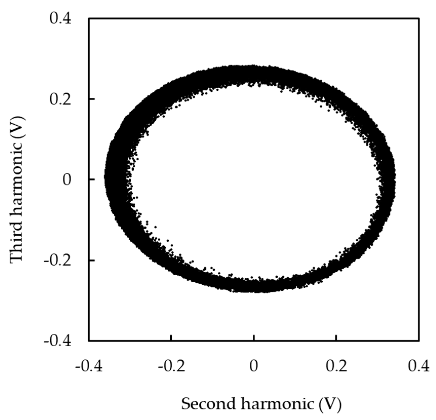
Figure 2 and
Figure 3 show experimental results of the axial error measurement. Two LIAs were used to detect second and harmonics and to remove anything unsynchronized with the reference signals. Hence, a Lissajous diagram using the harmonics was generated accurately even though the presence of environmental disturbance, as shown in
Figure 2.
Figure 3 shows the axial error of the spindle. An axial error of the spindle with a peak-to-peak value of 0.8 µm was successfully detected. The effect of vibration can be seen clearly at the peaks of the axial error measurement graph caused by the air gap of the ball bearings of the spindle. The length noise floor analyzed using FFT are shown in
Figure 3b. The result shows that a primary peak of 8.4 Hz, which is the same as the rotary frequency of the spindle axis, and its harmonics are found. The obtained noise level reaches less than 10 nm/√Hz from 1 Hz to 1000 Hz and downs to 0.01 nm/√Hz and lower at frequencies above 10 kHz instead of those unwanted peaks. Moreover, other redundant peaks found may be caused by this air gap of the ball bearings of the spindle above.
According to Equation (10), the measurement speed of the interferometer is limited by
fm. To obtain measurements of the radial error of the spindle with a speed of up to several m/s,
fm ~ tens of MHz should be achieved. In our previous works, it was difficult to restore an interferometric signal modulated with
fm ~ tens of MHz owing to the hardware limitation caused by the low bandwidth of LIAs [
22,
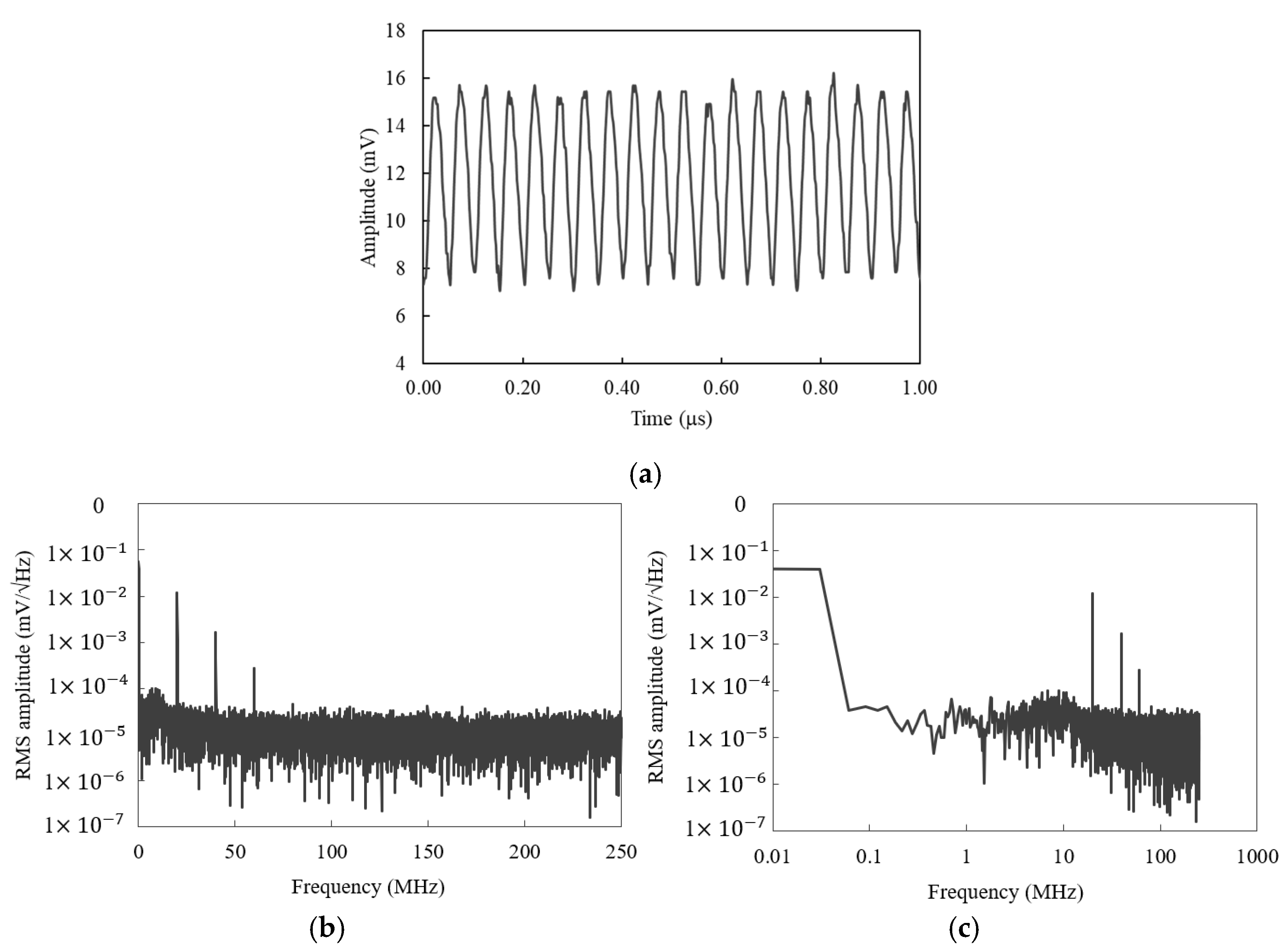
23]. In the following experimental step, we attempt to enhance the modulation frequency of LD up to 20 MHz using the new digital LIAs of the Moku: labs with a large bandwidth of 200 MHz for improving high-speed measurements. A digital oscilloscope (Moku: labs, San Diego, CA, USA) is employed to examine the modulated signal for one cycle period of ~30 μs at a sampling frequency of 500 Ms/s.
Figure 4 shows the measurement result. An
fm sine-wave modulation signal with a peak-to-peak amplitude of ~6.5 mV is graphed for 1 μs (one portion of 30 μs), as shown in
Figure 4a.
Figure 4b,c show the RMS amplitude of the signal in the frequency domain a bandwidth of 250 MHz and a frequency resolution of approximately 30.5 kHz using the FFT. A peak of 10
−2 mV/√Hz at
fm = 20 MHz is attained. Additionally, the 2nd and 3rd harmonics of
fm = 20 MHz were found, and the sine wave in
Figure 4a can be distorted. Unfortunately, since the spindle speed is limited, we have not acquired the high-speed measurement of both the axial and radial errors using
fm = 20 MHz. We are planning to execute this problem using high-speed spindle.


