Article

Effect of Unburned Pulverized Coal on the Melting Characteristics and Fluidity of Blast Furnace Slag

School of Metallurgy, Northeastern University, Shenyang 110819, China
*
Author to whom correspondence should be addressed.
Crystals 2021, 11(6), 579; https://doi.org/10.3390/cryst11060579
Submission received: 2 April 2021 / Revised: 17 May 2021 / Accepted: 19 May 2021 / Published: 21 May 2021
(This article belongs to the Topic Iron Concentrate Particles)

Abstract

:
A substantial amount of attention has been paid to viscosity due to its substantial effect on the fluid dynamics of molten blast furnace slag and slag metal reaction kinetics during the pyrometallurgy process. To clarify the influence mechanism of unburned pulverized coal (UPC) on blast furnace (BF) slag viscosity, the effects of different contents of UPC on the BF slag viscosity, free-running temperature and viscous flow activation energy were investigated. The slag viscosity was measured by the rotating cylinder method, and the microstructure of the cooled slag was observed by SEM. As a result, the main reason for a change in the slag viscosity, free-running temperature and viscous flow activation energy was that the UPC entering the slag formed a large number of white particles that predominantly comprised deposited carbon and a high melting point solid solution. In addition, the disintegration or polymerization of the Six O y z - structure was also a contributing factor. When the content of the UPC was 0.6%, the free-running temperature and viscous flow activation energy of slag were 1623 K and 120.969 kJ/mol, respectively, which are lower than those of the slag without UPC. However, the free-running temperature and viscous flow activation energy increased to 1668 K and 286.625 kJ/mol, respectively, when the content of UPC increased to 4%, which are higher than those of slag without UPC.

1. Introduction

It is widely known that the development of pulverized coal injection (PCI) technology is of revolutionary significance for modern BF ironmaking. This is specifically embodied in: (1) the replacement of expensive and increasingly scarce metallurgical coke with low-priced pulverized coal, which reduces the coke ratio of BF ironmaking and lowers the cost of pig iron; (2) the reduction of the number of coke ovens and the amount of coke produced, thereby reducing the environmental pollution caused by coking production; (3) the improvement of the working conditions of the BF hearth to make the BF run smoothly; (4) the creation of conditions for the BF to use a high blast temperature and an oxygen-enriched blast; (5) PCI being an effective method to adjust the heat condition system of BF; (6) the release of more hydrogen than coke in the process of pulverized coal gasification, which improves the reduction ability and penetration diffusion ability of coal gas, and is beneficial to ore reduction and the improvement of the BF operation index. At present, the coal injection ratio of advanced BFs can reach 200 kg/tHM (per tonne hot metal) [1], while the coal injection technology level of domestic BFs is still relatively low, with the coal injection ratio basically being maintained at 140~180 kg/tHM, among which Baosteel’s BF coal injection technology is the most advanced. Therefore, there is still much room for improvement in domestic BF coal injection technology. On the other hand, due to the increasing depletion of coking coal resources and the rising price of metallurgical coke, the production cost of steel enterprises is also increasing [2]. This is forcing many steel enterprises to pursue high coal injection ratios to alleviate the pressure of high production costs.
However, theoretical and experimental studies have found that the pulverized coal cannot be completely burned in the narrow space of the tuyere raceway, and a large amount of UPC appears in the BF as a result [3,4,5,6]. This is because the velocity of pulverized coal passing through the tuyere of BF is very high (it usually reaches 240 m/s) [7]. In addition, the hysteretic nature of the pulverized coal ignition process and the gasification of volatile matter (shown in Figure 1) results in there being no time for the pulverized coal to combust. The distribution of UPC in the BF and the various physical-chemical reactions involved are shown in Figure 2, including (1) participation in the carbon gasification reaction; (2) participation in the carburizing reaction of hot metal; (3) deposition in slag; (4) deposition in the cohesive zone and stock column; and (5) escape from the BF with the gas. Among these, UPC deposited in BF final slag affects the direct reduction reaction of iron, the direct reduction reaction of nonferrous elements, and the deposition reaction in the slag, thus affecting the BF slag viscosity [8,9,10]. BF slag viscosity has an important influence on smooth operation, heat transfer and mass transfer during the ironmaking process. These factors ultimately determine the rate of reaction, the discharge of impurities in the hot metal, the loss of metals in the molten slag, the desulfurization of hot metal, and the life of the BF lining. Therefore, BF slag must have an appropriate viscosity.
Many scholars at home and abroad have performed a lot of research on the behavior of UPC in BF. For example, Li et al. [11] and Xiang et al. [12] found that CO2 will react with UPC first, and then coke. Chai et al. [13] explored the influence of UPC on the gasification reaction of coke in BF, and the results showed that, in the soft melting zone, the gasification reaction model of coke blocks attached to the UPC corresponded to an unreacted core model and a porous volume-reacted model, jointly. The results of Zan et al. [14] showed that an increased heating rate is beneficial for the gasification reaction of the two UPCs. Ref. [15] also studied the carbon gasification behavior of UPC and found that the reaction mechanism of BUPC (UPC made from bituminous coal) with CO2 consists of random nucleation and growth, and the apparent activation energy is 96.24 kJ·mol−1; the reaction mechanism of AUPC (UPC made from anthracite) with CO2 follows the shrinkage spherical functional model, and the apparent activation energy is 133.55 kJ·mol−1. Ning et al. [2] investigated the catalytic behavior of alkali vapor on UPC prepared from bituminous coal, anthracite, semi coke and coke, and the results showed that the alkali metal vapor had a catalytic effect on the gasification reaction of UPC. Diao et al. [16] studied the effect of UPC on the BF slag viscosity in Panzhihua steel, and found that the reduction of TiO2 by UPC in the slag was the restrictive step affecting the slag viscosity. Zhou et al. [17] found that the BF slag increased with increasing UPC content under the same basicity, and the slag viscosity increased with increasing slag viscosity under the same UPC content. However, in Zhou’s research, all of the UPC in the BF entered the slag, which obviously did not conform to the actual situation. The research results of Liang et al. [18] showed that a small amount of UPC can decrease the viscosity and melting temperature of BF slag. Moreover, many researchers [19,20,21,22,23,24,25] have focused on the effects of various chemical components on the slag viscosity, including MgO, Al2O3 and CaO/SiO2. However, the previous research is too superficial, only discussing the surface phenomena, is lacking in more in-depth theoretical analysis. Additionally, the influence mechanism of UPC on the viscosity of BF slag has also rarely been studied.
Based on the above analysis, in this paper the viscosity changes of BF slag with different contents of UPC were measured, and the distribution of UPC in the BF slag was analyzed. The mechanism of the effect of UPC on the BF slag viscosity is revealed by using slag ionic theory and phase diagram theory.

2. Materials and Methods

2.1. Materials

The raw pulverized coal and the slag used in this study were provided by a 4070 m3 BF in China. It is impossible to obtain UPC from a BF. Therefore, the raw pulverized coal was placed in a high-temperature heating furnace and heated to 1100 °C for 1 h to achieve dry distillation under anaerobic conditions in the laboratory and then cooled to room temperature under a nitrogen atmosphere to obtain the UPC. The UPC particle size less than 0.074 mm accounted for 70% of the total. The proximate and composition analyses of UPC are shown in Table 1. The slag was ground into a powder using a ball mill. The composition of the slag is shown in Table 2.

2.2. Experimental Equipment and Methods

2.2.1. Proportion of UPC

The proportion of UPC is mainly determined according to the actual BF coal injection ratio and slag iron ratio, as shown in Equation (1).
w f = Q 1 × ( 1 B u r n o u t ) × w 1 Q 2 × 100 %
where wf is the proportion of UPC in the BF slag, wt%; w1 is the amount of UPC entering BF slag, %; Q1 is the coal injection ratio, kg/tHM; Burnout is the burnout rate of pulverized coal, %; Q2 is the slag iron ratio, kg/tHM.
According to the actual production data of the BF, the coal injection ratio is 130 kg/tHM and the slag iron ratio is 290 kg/tHM. The burnout rate of pulverized coal was determined to be 70% based on Liu’s research results [26]. According to the research results of Du et al. [27] and Zhao [28], combined with the progress of modern BF operation, it was determined that the amount of UPC entering BF slag was 15%. Based on the above analysis, the mass fractions of UPC to be added into the BF slag were determined to be 0, 0.6, 0.8, 2 and 4 wt%.

2.2.2. Experiment on Effect of UPC on BF Slag Viscosity

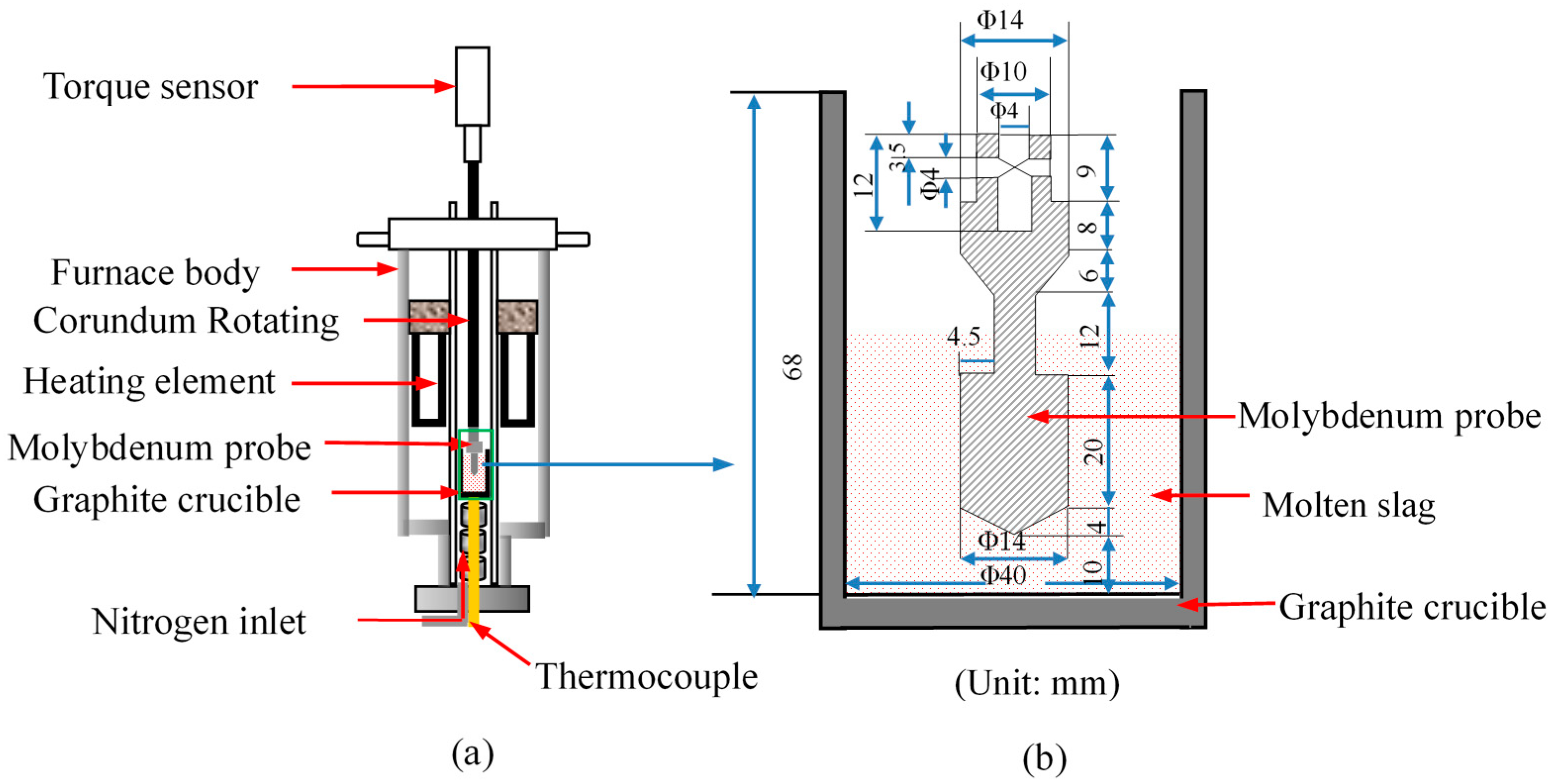
In this study, the slag viscosity was measured by the rotating cylinder method using a model RTW-10 physical property comprehensive testing instrument with a digital viscometer developed by Northeastern University. The experimental apparatus is shown in Figure 3. The viscometer system was calibrated by silicone oil standards. Before each viscosity measurement, the analytical reagent castor oil with a known viscosity (0.451, 1.986, and 2.148 Pa·s) at different temperatures was used to check the accuracy of the viscometer equipment, and the relative error of the measurements was less than 1%.
In each run, the mixed sample of slag and UPC was placed in a graphite crucible. Then, the graphite crucible was placed in the furnace, and the furnace was programmed to heat at a rate of 5 °C min−1. After the sample was completely melted, the temperature of the slag was maintained for 10 min at approximately 1500 °C by using the molybdenum bar to stir the slag for three minutes. Then the molybdenum probe connected to the torque sensor was put into the molten slag to measure the slag viscosity. The system automatically measured the viscosity every 1 K and recorded it.
Considering the actual production process of a BF, the molten slag herein was discharged from the BF and flowed into the slag ladle through a slag runner. During this process, the molten slag was exposed to the air, and there was not enough time to achieve chemical equilibrium. Therefore, the slag viscosity was measured during continuous cooling. A total of 140 g of slag was mixed with different UPC contents (0, 0.6, 0.8, 2 and 4 wt%) and used for each experiment.

2.2.3. Microscopic Characterization

The micromorphology of the BF slag after the experiment was characterized using a scanning electron microscope JSM-6490LV (JEOL, Tokyo, Japan).

2.2.4. Definition of Slag Free-Running Temperature

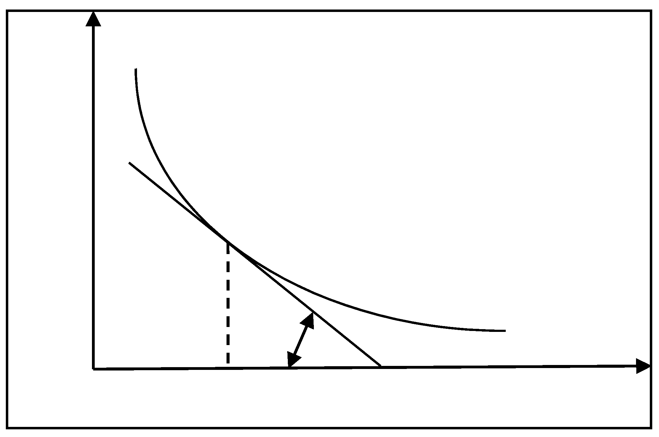
The free-running temperature of a slag is the lowest temperature at which the slag can flow freely after melting. It is defined as the temperature corresponding to the tangent point of the viscosity–temperature curve and a 45 degree line, as shown in Figure 4.

3. Results and Discussion

3.1. Effect of the UPC on the Slag Viscosity

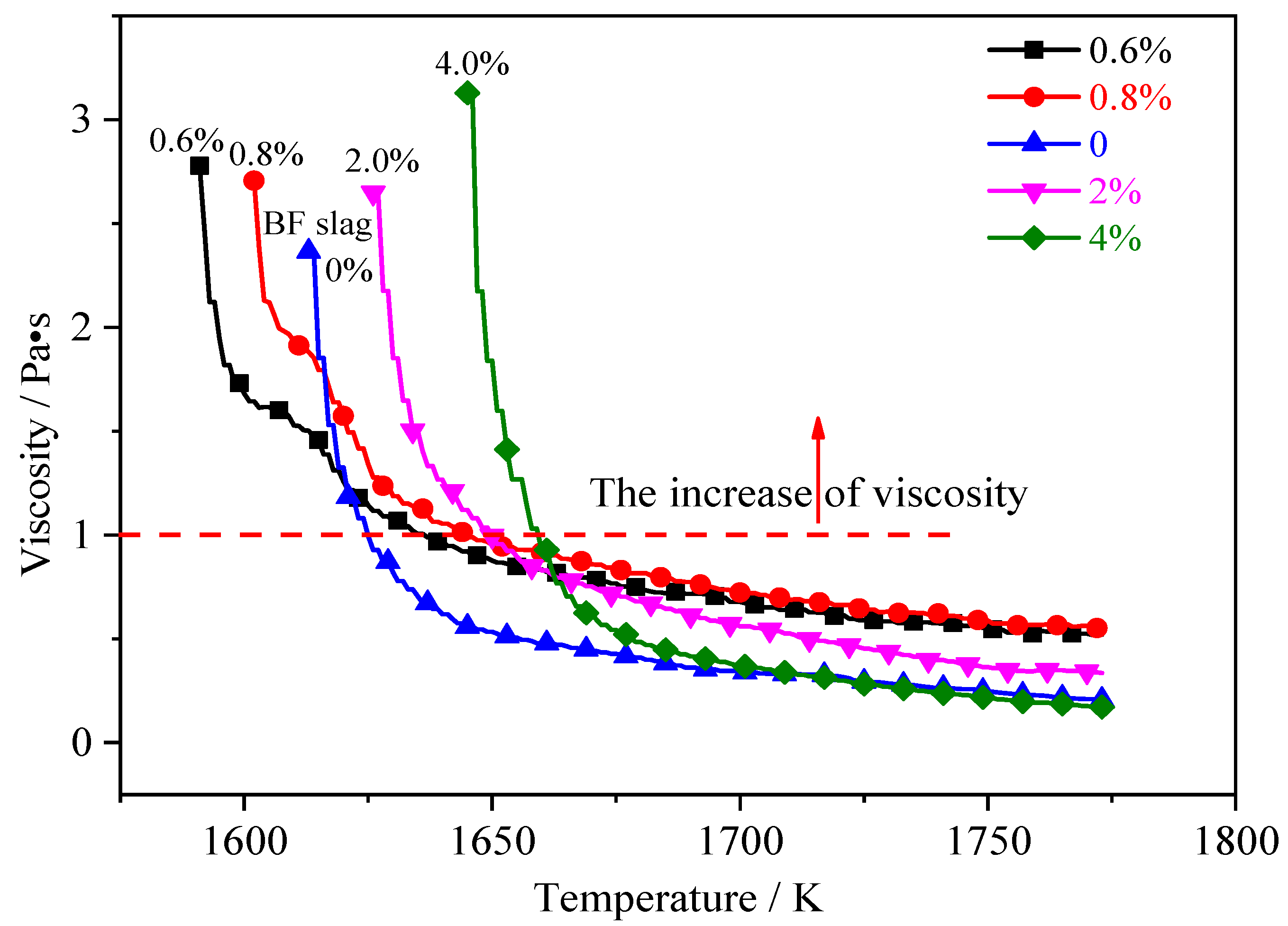
Figure 5 shows the effect of the different UPC contents on BF slag viscosity. The viscosity curve shows that there is a significant turning point during the cooling process. Both the process of the formation of nuclei by ions and the formation of new crystalline phases by mass transfer require little diffusion activation energy and time because the molten slag contains a large number of complex ions with a small size and fast migration rate. The temperature of the molten slag was cooled to the liquidus temperature as the temperature decreased. Moreover, the molten slag quickly transforms to a heterogeneous state with a continuous precipitation of crystalline phases that eventually decrease its fluidity. When the BF is operating normally, the suitable viscosity range of BF slag is between 0.3 and 0.5 Pa·s. It can be seen from Figure 5 that the viscosity of the BF slag increases sharply when the viscosity is higher than 1.0 Pa·s.
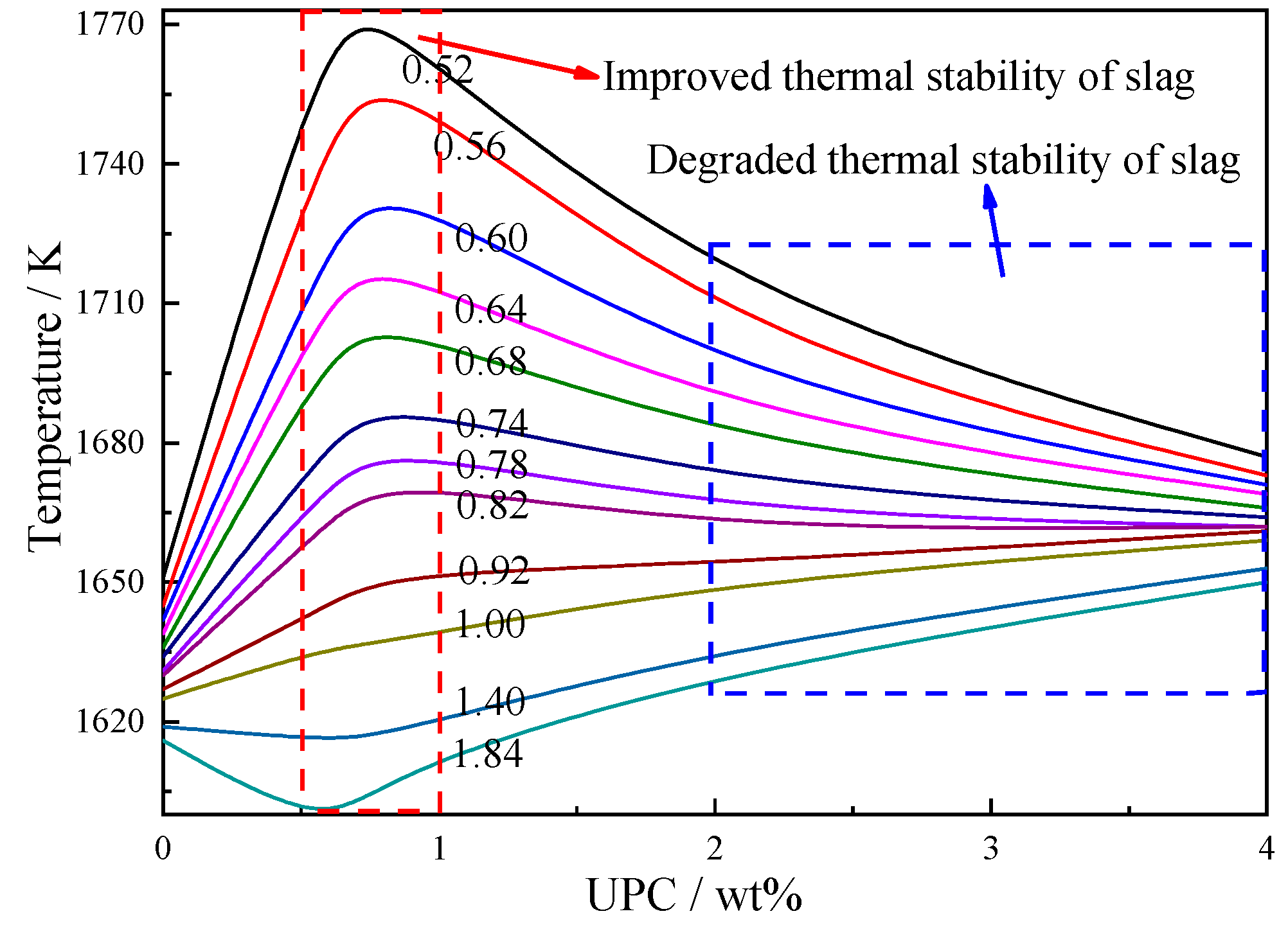
It can be seen in Figure 5 that the effect of the UPC on slag viscosity is not obvious at high temperatures (1698–1773 K), and the slag viscosity is basically stable at approximately 0.5 Pa·s. As the cooling progresses, the viscosity of the slag with the content of UPC ranging from 0.6 wt% to 0.8 wt% begins to rise sharply at low temperatures compared with that of the slag without UPC. However, the viscosity of the slag with UPC greater than 2 wt% begins to rise sharply at high temperatures. The above results illustrate that the UPC can dilute the slag viscosity when its content is low; that is, a low UPC content can reduce the slag viscosity. This result is consistent with the findings of Liang et al. [18]. The UPC causes the slag viscosity to increase when the UPC content in the slag exceeds a certain value. The iso-viscosity curve is presented in Figure 6, where the iso-viscosity curve becomes sparse when the content of UPC is in the region of approximately 1 wt%, which indicates that UPC can reduce the influence of temperature on the viscosity. In addition, the iso-viscosity curves become close when the content of UPC is in a high range, indicating that the slag viscosity increases sharply with a decrease in the temperature when the same UPC content is present. That is, the thermal stability of the slag starts to deteriorate with increasing UPC content.

3.2. Effect of the UPC on the Free-Running Temperature of the Slag

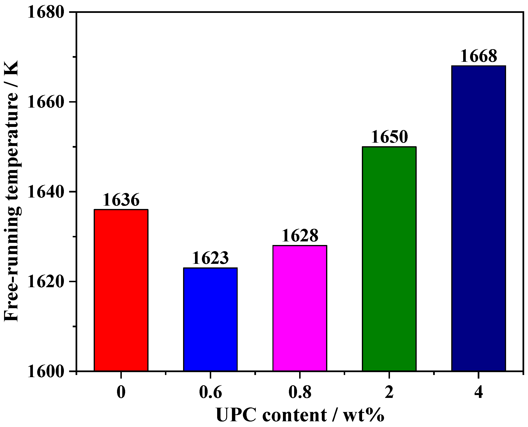
The free-running temperatures of the slag with different UPC contents are shown in Figure 7, and it can be seen that the free-running temperature of the slag with a UPC content of 0.6–0.8 wt% is lower than that of the slag without UPC (1636 K), which indicates that a small amount of UPC reduces the free-running temperature of the slag. When the content of UPC in the slag is 2–4 wt%, the free-running temperature of the slag rises from 1650 K to 1668 K, which indicates that the UPC increases the free-running temperature of the slag when the UPC content exceeds a certain value. Therefore, we can conclude that when the content of UPC in BF slag is 4 wt%, the coal injection ratio is 257.78 kg/tHM calculated according to Formula 1. At this time, in order to decrease the content of UPC in BF slag to 2 wt%, it is necessary to increase the burnout rate of pulverized coal to 85%.

3.3. Viscous Flow Activation Energy of the Slag

The viscosity of a homogeneous slag complies with the law of a Newtonian viscous liquid. The viscosity depends on the activation energy of the moving particles, and the relationship between the viscosity and activation energy can be described by Arrhenius-type equation [29]:
η = B 0 e x p ( E η R T )
where η is the viscosity, Pa·s; B0 is the Arrhenius constant; Eη is the viscous flow activation energy, kJ/mol; R is the gas constant, 8.314 J/(mol·K); and T is the temperature, K.
The Arrhenius-type equation can be rearranged after taking the logarithm:
Ln η = Ln B 0 + E η R T
Equation (3) shows that there is a linear relationship between Lnη and 1/T, and the viscous flow activation energy Eη can be obtained from the slope of the line. This equation is only applicable to homogeneous slags because the properties of slags change when the temperature is lower than the free-running temperature. Therefore, the free-running temperature is used as the critical temperature; that is, the viscosity between the free-running temperature and 1773 K is used to calculate the viscous flow activation energy. The calculation results are shown in Figure 8 and Table 3.
Table 3 shows that when the content of UPC is 0.6 wt% and 0.8 wt%, the values of viscous flow activation energy are 120.969 kJ/mol and 124.419 kJ/mol, respectively, which are lower than that (187.115 kJ/mol) for the sample without UPC. However, when the content of UPC increases to 2 wt% and 4 wt%, the viscous flow activation energy increases to 212.115 kJ and 286.625 kJ, respectively. The above results show that a small amount of UPC decreases the viscous flow activation energy of the slag, which improves the flow of the slag. However, the flow of the slag becomes difficult when the content of UPC exceeds a certain ratio. Moreover, this result is also consistent with a change in the slag viscosity.

3.4. Theoretical Analysis

Several theories about slag structure have been proposed, such as the molecular and ion theories. The slag ion theory relies on the structure, electric conductivity, and ionic migration number of a slag, and these values can be determined by modern detection techniques, such as X-ray diffraction (XRD), electron microscopy, Raman spectroscopy, and electrochemical methods. The slag ion theory holds that the slag is composed of charged particles, and the force between ions comprises the Coulomb force. The forms of the positive and negative ions in slag are related to the force between the charged particles. The main existing states of the ions are shown in Reactions (4)–(6).
The existing forms of the simple positive and negative ions are shown as follows:
CaO ⇄ Ca2+ + O2−
MnO ⇄ Mn2+ + O2−
MgO ⇄ Mg2+ + O2−
……
The existing forms of complex anions are shown as follows:
SiO 2 + 2 O 2 SiO 4 4 Fe 2 O 3 + O 2 2 FeO 2 P 2 O 5 + 3 O 2 2 PO 4 3
The polymerizations and decompositions of complex anions are shown as follows:
SiO 4 4 + SiO 4 4 Si 2 O 7 6 + O 2 3 SiO 4 4 Si 3 O 10 8 + 2 O 2
It is well known that Six O y z is the main composite anion and the main flow unit in molten silicate melts. These Six O y z composite anions consist mainly of SiO 4 4 tetrahedra units. The Six O y z structure is disintegrated or polymerized when the composition of a molten slag changes; that is, the structure of Six O y z changes from a simple to a complex one or from a complex to a simple one (as shown in Figure 9). This eventually leads to an increase or decrease in the slag viscosity.
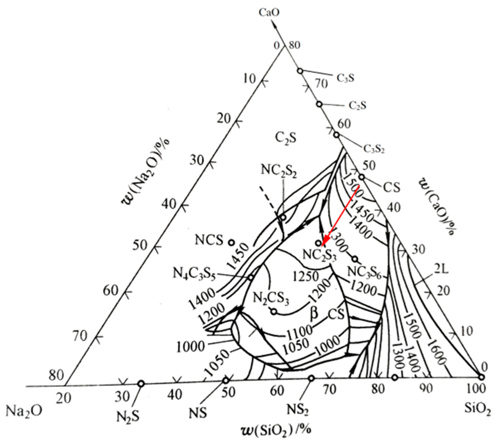
It can be seen from the composition of the slag in Table 2 that (w (CaO)%)/(w(SiO2)%) ≈1.17. In addition, there is an obvious turning point in the viscosity–temperature curve in Figure 5, and the temperature range of the slag solidification process is narrow; therefore, the slag is determined to be a basic slag. According to the slag ion theory, the main reasons for the decrease in the viscosity are as follows. (1) The basic oxides CaO and MgO in the UPC enter the slag and dissociate into cations and oxygen ions (such as Ca2+, Mg2+ and O2−), which destroy the bridging oxygen bonds in Six O y z , thus simplifying the structure of the Six O y z . (Bridging oxygen is the oxygen that connects two tetrahedrons [30] and plays a very important role in the Six O y z network structure, and its content has a direct impact on the complexity of the system.) The transformation mechanism of the Six O y z network structure is as follows: ≡Si—O—Si≡+MO⇄≡Si—O—M—O—Si≡ and ≡Si—O—Si≡+MO⇄≡2(Si—O) + M2+ [31]. (2) When the monovalent alkali oxides (such as Na2O, K2O) enter the slag, they provide two monovalent cations (2Na+, 2K+) and one oxygen ion (O2−). This results in a fracture in the network structure; that is, the effect of monovalent alkali oxides on reducing the slag viscosity is strong. At this time, the transformation mechanism of the Six O y z network structure is as follows: Si—O—Si ≡ + M2O⇄2 ≡ Si—O—M. (3) When K2O and Na2O enter the CaO-SiO2 system, they form a series of low-melting compounds, as shown in Figure 10, which reduce the melting point and viscosity of slag. (4) The Fe2O3 entering the slag is reduced to FeO by carbon. According to the ternary phase diagram of SiO2-CaO-FeO (Figure 11), the liquidus temperature of CaO-SiO2 and 2CaO-SiO2 solid solutions decreases with increasing FeO content; that is, FeO can effectively reduce the melting point of the slag, thus reducing the viscosity. In addition, iron oxide can provide free oxygen ions through the following reactions to break the structure of the silicate anions: FeO = Fe2+ + O2−, Fe2O3 = 2FeO2+ + O2−.
When the content of UPC in the slag is approximately 2–4 wt% (as in the present BF slag), the slag viscosity and viscous flow activation energy increase significantly. The main reasons are as follows. (1) The content of SiO2 and Al2O3 entering the slag is relatively high, and the following reactions occur in a basic slag: SiO2 + 2O2− SiO 4 4 - and Al2O3 + O2− = 2 AlO 2 1 - , resulting in an increase in the n(Si)/n(O) atomic ratio. Moreover, SiO2 is converted into a complex ion by consuming O2−, and thus many SiO 4 4 - units share one O2− to form a more complex ion. As more SiO 4 4 - is polymerized, more O2− is shared, and the structure of the silica–oxygen complex ion becomes more complex (from the point, line and surface of the body). In addition, the empirical formula of anions in the range of Si/O = 0.25–0.33 is shown in Table 4 [32], which indicates that the structure of the silica–oxygen complex ions tends to increase in complexity with an increase in the Si/O atomic ratio. (2) Al2O3 can absorb oxygen ions to form AlO 4 5 - complex ion groups, forming complex compounds with strong crystallinity and a high melting point. As described in several published studies [33,34,35,36], Al3+ cations can replace the tetrahedrally coordinated Si4+ polyanions to form Al3+ polyanions of [AlO4]5− tetrahedra. Upon the further addition of Al2O3, Al3+ no longer exists in tetrahedral sites as a substitute for Si4+ but behaves as a network modifier and exists in the [AlO6]9− octahedral configuration, similar to the behavior of Ca2+, as depicted by Sohn and Min [37]. In this study, Al2O3 behaves as a network former and increases the slag viscosity. (3) The main reason is that the UPC entering the slag exists as suspended solid particles. Figure 12a shows a molybdenum probe after measuring the viscosity of the slag containing 4 wt% UPC. Some slag adhered to the molybdenum probe, and some undissolved carbon adhered to the slag. Figure 12b shows the molten state of the slag containing 4 wt% UPC at high temperature, and the UPC (the blue circle in the picture) exists as a suspension and can be clearly observed in the slag. These solid particles have a high dispersion and large specific surface area. Therefore, surplus surface energy can cause these solid particles to strongly adsorb onto other particles, which undoubtedly increases the volume of the particles and ultimately leads to a sharp increase in the slag viscosity.

3.5. Analysis of the Slag Microstructure

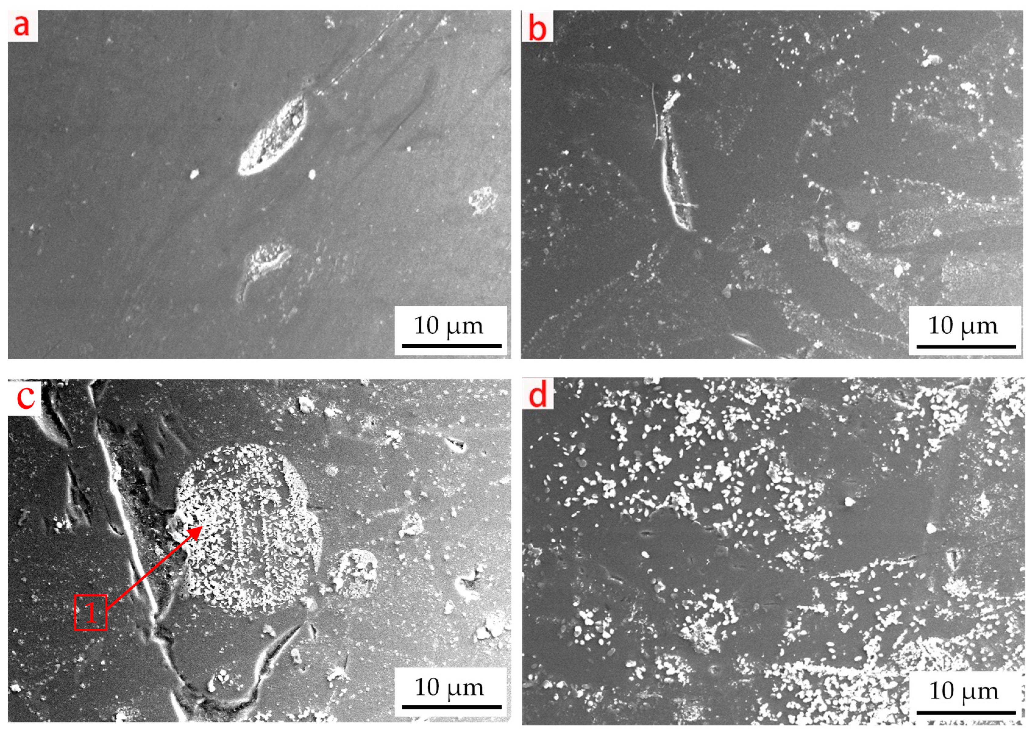
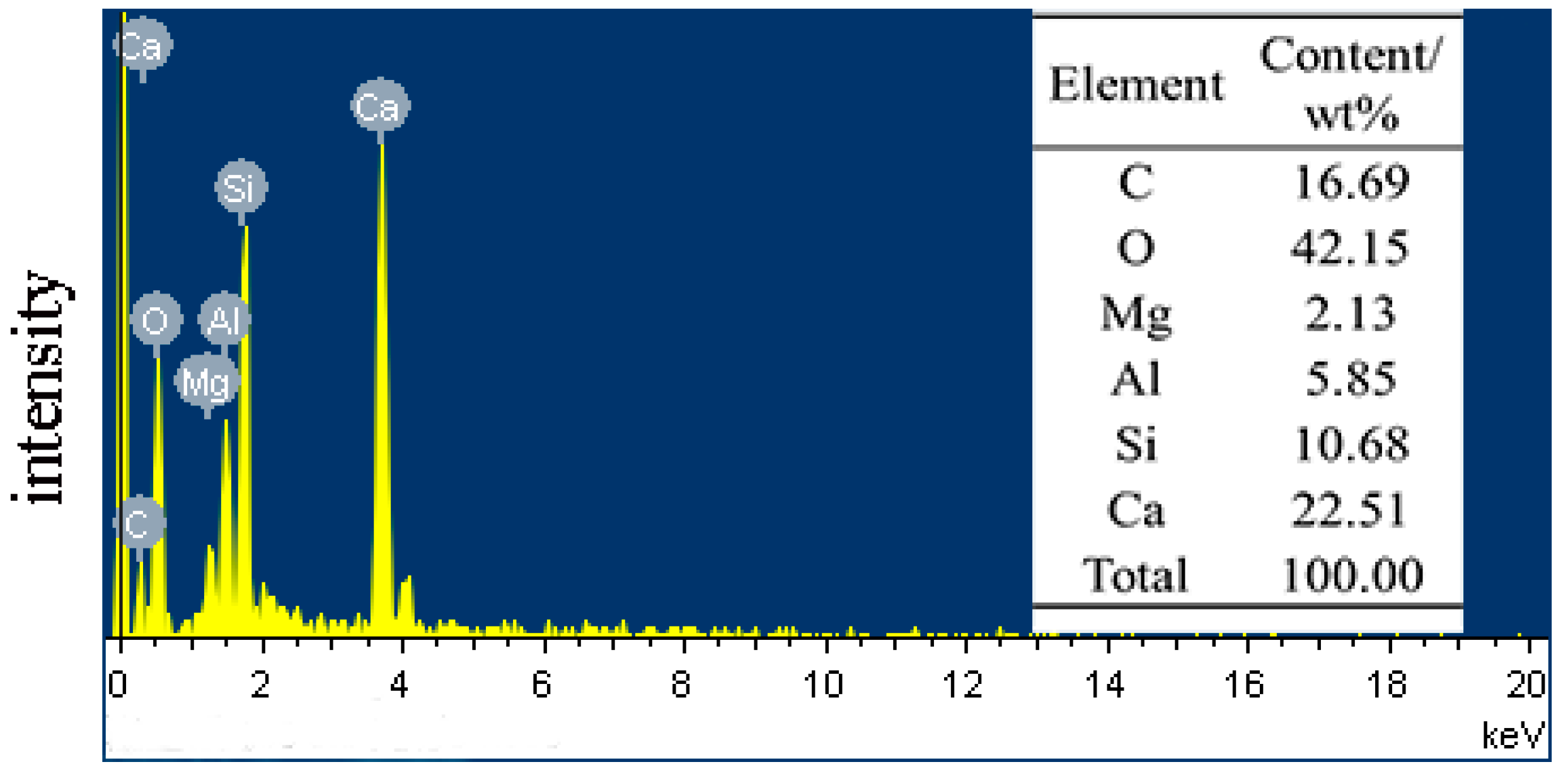
Figure 13 shows the surface micromorphology of the slag cooled with different contents of UPC. It is obvious that the number of white particles in the slag increases with increasing UPC content. When the content of UPC in the slag is 0.6 wt% and 0.8 wt%, the white particles decrease and punctate. However, when the content of UPC is increased to 2 wt% and 4 wt%, the number of white particles increases, and they transform from “punctiform” to “schistose” in character. This is the main reason for the increase in the viscous flow activation energy and slag viscosity. Figure 14 shows an energy-dispersive spectroscopy (EDS) analysis of the white particles in the slag (Point 1 in Figure 13c), and the result indicates that the white particles mainly comprise deposited carbon and a high-melting-point solid solution around it. These white particles form heterogeneous phases during slag cooling, which ultimately lead to the increase in the slag viscosity, free-running temperature, and viscous flow activation energy.

4. Conclusions

  • When the content of UPC in the slag is less than 0.8 wt%, the slag viscosity, free-running temperature and viscous flow activation energy decrease. This is due to the breakdown of the complex spatial network structure of SixOz− y in the slag and the formation of a series of complex compounds with low melting points. Thus, the low content of UPC has the function of diluting the slag to some extent.
  • When the content of UPC is in the range of approximately 0.5–1 wt%, the UPC reduces the effect of the temperature on the slag viscosity. When the content of UPC is in the range of approximately 2–4 wt%, the thermal stability of the slag begins to deteriorate, and the UPC has a negative effect on the slag viscosity. To decrease the content of UPC in BF slag to 2 wt%, it is necessary to increase the burnout rate of pulverized coal to 85%.
  • The free-running temperature and viscous flow activation energy of slag without UPC are 1626 K and 187.115 kJ/mol, respectively. When the content of UPC in the slag is 0.6 wt%, the free-running temperature and viscous flow activation energy decrease to 1623 K and 120.969 kJ/mol, respectively. However, when the content of UPC increases to 4 wt%, the free-running temperature and viscous flow activation energy increase to 1668 K and 286.625 kJ/mol, respectively.
  • When the content of UPC in the slag is high, the main factor affecting the change in the slag viscosity, free-running temperature and viscous flow activation energy is that the UPC entering the slag forms a large number of white particles that are composed of deposited carbon and a high melting point solid solution. These white particles form heterogeneous phases during slag cooling.

Author Contributions

Data curation, Q.G.; Methodology, D.X.; Project administration, F.S.; Software, H.Z.; Writing—original draft, D.X.; Writing—review & editing, X.J. All authors have read and agreed to the published version of the manuscript.

Funding

This work was funded by the National Science Foundation of China (51874080, 51974073, 52074086 and 51774071), the Foundational Research Funds of Zhongye Changtian International Engineering CO., LTD, China (2020JCYJ03), the Fundamental Research Funds for the Central Universities, China (N2125029) and Natural Science Foundation of Liaoning (2019-MS-132), respectively.

Institutional Review Board Statement

Not applicable.

Informed Consent Statement

Not applicable.

Data Availability Statement

Data sharing not applicable.

Conflicts of Interest

The authors declare no conflict of interest.

References

  1. Shen, Y.; Guo, B.; Yu, A.; Austin, P.; Zulli, P. Three-dimensional modelling of in-furnace coal/coke combustion in a blast furnace. Fuel 2011, 90, 728–738. [Google Scholar] [CrossRef]
  2. Ning, X.; Peng, Z.; Wang, G.; Zhang, J.; Song, T. Experimental study on gasification mechanism of unburned pulverized coal catalyzed by alkali metal vapor. J. Energy Inst. 2020, 93, 679–694. [Google Scholar] [CrossRef]
  3. Hur, N.S.; Cho, B.R.; Choi, J.S.; Hanand, K.W.; Seo, K.Y. High Coal Injection into the Blast Furnace under Productivity. Rev. Metal. CIT 1996, 93, 367–377. [Google Scholar] [CrossRef]
  4. Steeghs, A.; Schoone, E.; Toxopeus, H. High injection rates of coal into the blast furnace. MPT Metal. Plant. Technol. Int. 1994, 17, 58–65. [Google Scholar]
  5. Kinura, K.; Kishimoto, S.; Sakai, A.; Triyama, T.; Sato, M. Challenge to the highest PC rate operating at Fu-kuyama NO.4 BF. Rev. Metal. CIT 1996, 93, 575–580. [Google Scholar] [CrossRef]
  6. Takahashi, K.; Kawai, H.; Suzuki, Y. analysis of stress and buoyancy for solids flow in the low part of a blast furnace. Chem. Eng. Sci. 2002, 57, 215–226. [Google Scholar] [CrossRef]
  7. Yu, X.; Shen, Y. Modelling of blast furnace with respective chemical reaction in coke and ore burden layers. Metall. Mater. Trans. B 2018, 49, 2370–2388. [Google Scholar] [CrossRef]
  8. Iwanaga, Y. Investigation on behavior of unburnt pulverized coal in blast furnace. ISIJ Int. 1991, 31, 494–499. [Google Scholar] [CrossRef] [Green Version]
  9. Su, B.; Zhang, J.; Yan, B.; Che, X.; Wang, G.; Hu, Z. Study on the microstructure and behaviour of unburnt pulverized coal in BF. Adv. Mater. Res. 2011, 236–238, 858–863. [Google Scholar] [CrossRef]
  10. Diao, R.S.; Hu, B.S. Behavior of unburned particle in blast furnace pulverized coal injection. Iron Steel Vanadium Titan. 2003, 24, 18–21. [Google Scholar]
  11. Li, Y.; Zhang, J.; Wang, G.; Liang, W.; Zhang, N.; Guo, P. Assessment on the effect of unburned pulverized coal on the properties of coke in blast furnace. Ironmak. Steelmak. 2020, 47, 228–237. [Google Scholar] [CrossRef]
  12. Xiang, D.; Shen, F.; Jiang, X.; Yang, J.; Li, J.; Gao, Q. protective mechanism of unburned pulverized coal to coke in blast furnac. J. Min. Metal. Sect. B Metal. 2019, 55, 371–380. [Google Scholar] [CrossRef] [Green Version]
  13. Chai, Y.; Luo, G.; An, S.; Peng, J.; Wang, Y. Influence of unburned pulverized coal on gasification reaction of coke in blast furnace. High Temp. Mater. Proc. 2019, 38, 733–738. [Google Scholar] [CrossRef]
  14. Zan, R.; Wang, W.; Xu, R.; Schenk, J.; Zheng, H.; Wang, X. Gasification Characteristics and Kinetics of Unburned Pulverized Coal in Blast Furnaces. Energies 2019, 12, 4324. [Google Scholar] [CrossRef] [Green Version]
  15. Xiang, D.; Shen, F.; Yang, J.; Jiang, X.; Zheng, H.; Gao, Q.; Li, J. Combustion characteristics of unburned pulverized coal and its reaction kinetics with CO2. Int. J. Miner. Metal. Mater. 2019, 26, 811–821. [Google Scholar] [CrossRef]
  16. Diao, R.S.; Hu, B.S. Influence of unburned PCI on the blast furnace slag viscosity in Panzhihua Steel Co. Iron Steel 2004, 39, 14–16. [Google Scholar]
  17. Zhou, L.; Zhao, J. Effects on slag viscosity caused by UPC. J. Anhui Univ. Technol. 2004, 21, 1–3. [Google Scholar]
  18. Liang, Z.; Shen, S. Effect of unburned pulverized coal on slag viscosity. Metall. Sichuan 1996, 3, 20–21. [Google Scholar]
  19. Kim, J.; Lee, Y.; Min, D.; Jung, S.; Yi, S. Influence of MgO and Al2O3 contents on viscosity of blast furnace type slags containing FeO. ISIJ Int. 2004, 44, 1291–1297. [Google Scholar] [CrossRef]
  20. Gupta, V.; Seshadri, V. Studies on viscosity of high alumina blast furnace slags. Trans. Indian Inst. Met. 1973, 26, 55–64. [Google Scholar]
  21. Singh, R. Viscosity measurements of high alumina blast furnace slags. Steel India 1984, 7, 73–83. [Google Scholar]
  22. SUN, C.; Liu, X.; Li, J.; Yin, X.; Song, S.; Wang, Q. Influence of Al2O3 and MgO on the viscosity and stability of CaO-MgO-SiO2-Al2O3 Slags with CaO/SiO2 = 1.0. ISIJ Int. 2017, 57, 978–982. [Google Scholar] [CrossRef] [Green Version]
  23. Chen, M.; Zhang, D.; Kou, M.; Zhao, B. Viscosities of Iron Blast Furnace Slags. ISIJ Int. 2014, 54, 2025–2030. [Google Scholar] [CrossRef] [Green Version]
  24. Yan, Z.; Lv, X.; Zhang, J.; Qin, Y.; Bai, C. Influence of MgO, Al2O3 and CaO/SiO2 on the viscosity of blast furnace type slag with high Al2O3 and 5 wt% TiO2. Can. Metal. Q. 2016, 55, 186–194. [Google Scholar] [CrossRef]
  25. Zhang, X.; Jiang, T.; Xue, X.; Hu, B. Influence of MgO/Al2O3 Ratio on Viscosity of Blast Furnace Slag with High Al2O3 Content. Steel Res. Int. 2016, 87, 87–94. [Google Scholar] [CrossRef]
  26. Liu, Y.; Shen, Y. Three-dimensional modelling of charcoal combustion in an industrial scale blast furnace. Fuel 2019, 258, 116088. [Google Scholar] [CrossRef]
  27. Du, H.; Nie, D. the study on behavior of unburned pulverized coal in blast furnace. Ironmaking 1988, 4, 1–7. [Google Scholar]
  28. Zhao, Z. Behavior of unburnt pulverized coal in blast furnace. Henan Met. 1988, 2, 10–42. [Google Scholar]
  29. Hu, K.; Lv, X.; Li, S.; Song, B.; Han, K. Viscosity of TiO2-FeO-Ti2O3-SiO2-MgO-CaO-Al2O3 for high-titania slag smelting process. Metal. Mater. Trans. B 2018, 49, 1963–1973. [Google Scholar] [CrossRef]
  30. Wu, T.; Wang, Q.; Yao, T.; He, S. Molecular dynamics simulations of the structural properties of Al2O3-based binary systems. J. Non Cryst. Solids 2016, 435, 17–26. [Google Scholar] [CrossRef]
  31. Zhang, Z.; Wang, Z.; Liang, Q.; Guo, Q.; Yu, G.; Yu, Z. Analysis and prediction of the viscosity of the SiO2-Al2O3-CaO ternary system in completely molten state. Proc. Chin. Soc. Electr. Eng. 2008, 28, 39–43. [Google Scholar]
  32. Tiwary, J.; Sarkar, S.; Mishra, B.; Mohanty, U. Structural aspects of blast furnace slag. ICE Publ. 2013, 2, 152–162. [Google Scholar] [CrossRef]
  33. Mills, K. The influence of structure on the physic-chemical properties of slags. ISIJ Int. 1993, 33, 148–155. [Google Scholar] [CrossRef]
  34. Park, J.; Min, D.; Song, H. Amphoteric behavior of alumina in viscous flow and structure of CaO-SiO2(-MgO)-Al2O3 slags. Metal. Mater. Trans. B 2004, 35, 269–275. [Google Scholar] [CrossRef]
  35. Henserson, G.; Calas, G.; Stebbins, J. The structure of silicate glasses and melts. Elements 2006, 2, 269–273. [Google Scholar] [CrossRef]
  36. Xing, X.; Du, Y.; Zheng, J.; Wang, S.; Ren, S.; Ju, J. Isothermal Carbothermal Reduction of FeTiO3 Doped with MgO. JOM 2021, 73, 1328–1336. [Google Scholar] [CrossRef]
  37. Sohn, I.; Min, D. A review of the relationship between viscosity and the structure of calcium-silicate-based slags in ironmaking. Steel Res. Int. 2012, 83, 611–630. [Google Scholar] [CrossRef]
Figure 1. The combustion and gasification of the pulverized coal in the tuyere.
Crystals 11 00579 g001
Figure 2. Behavior of UPC in a BF.
Crystals 11 00579 g002
Figure 3. Experimental apparatus for slag viscosity measurement (a) and graphite crucible (b).
Crystals 11 00579 g003
Figure 4. Definition of the free-running temperature of slag.
Crystals 11 00579 g004
Figure 5. Viscosity of the slag as a function of the temperature for different UPC contents (0%, 0.6%, 0.8%, 2% and 4%).
Crystals 11 00579 g005
Figure 6. Influence of the UPC content and temperature on the BF slag viscosity.
Crystals 11 00579 g006
Figure 7. The free-running temperature of the slag with different UPC contents.
Crystals 11 00579 g007
Figure 8. The relationship between lnη and 1/T.
Crystals 11 00579 g008
Figure 9. Transformation process of the Six O y z structure.
Crystals 11 00579 g009
Figure 10. Phase diagram of the CaO-SiO2-Na2O slag system.
Crystals 11 00579 g010
Figure 11. Phase diagram of the SiO2-CaO-FeO slag system.
Crystals 11 00579 g011
Figure 12. The molybdenum probe after experiment (a), and the slag in molten stage (b).
Crystals 11 00579 g012
Figure 13. Surface micromorphology of the slags with different contents of UPC: (a) 0.6 wt% UPC, (b) 0.8 wt% UPC, (c) 2 wt% UPC and (d) 4 wt% UPC.
Crystals 11 00579 g013
Figure 14. EDS analysis of white particles in the slag (Point 1 in Figure 13c).
Crystals 11 00579 g014
Table 1. Proximate and chemical analyses of the UPC, wt%.
Proximate Analysis
Fixed CarbonMoistureAshVolatile Matters
79.880.8811.487.76
Analysis of ash
SiO2CaOAl2O3MgOTiO2Fe2O3K2ONa2OOthers
47.124.9235.551.041.996.110.720.711.84
Table 2. Chemical composition of the slag, wt%.
SiO2CaOAl2O3MgOTiO2FeOMnOSOthers
33.3438.9415.597.790.590.360.221.102.07
Table 3. Dynamics parameters of the viscous flow activation energy.
UPC ContentsFitting LineEη (kJ/mol)B0/(N·s·m−2)R2
0.6y = 14,550 x − 8.926120.9691.33 × 10−40.97
0.8y = 14,965 x − 9.094124.4191.12 × 10−40.98
0y = 22,506 x − 14.274187.1156.32 × 10−70.99
2y = 25,513 x − 15.564212.1151.74 × 10−70.99
4y = 34,475 x − 21.237286.6255.98 × 10−100.99
Table 4. Empirical formulas of the anions in the range of Si/O = 0.25–0.33 (66–50% MO).
Si/OCaO/SiO2Percentage of Molar Oxide Length   of   Chain   ( A ) Empirical Formula
0.2502 CaO·SiO2661 SiO 4 4
0.2863 CaO·2SiO2602 SiO 7 6
0.3004CaO·3SiO2573 SiO 10 8
0.3075CaO·4SiO2554 SiO 13 10
0.3126CaO·6SiO2546 SiO 16 12
0.32211CaO·10SiO25210 SiO 31 22
0.333CaO·SiO250Sin O 3 n 2 n
Publisher’s Note: MDPI stays neutral with regard to jurisdictional claims in published maps and institutional affiliations.