Article

Experimental and Numerical Study of Transient Liquid Phase Diffusion Bonded DZ40M Superalloys

State Key Laboratory of Advanced Welding and Joining, Harbin Institute of Technology, Harbin 150001, China
*
Author to whom correspondence should be addressed.
Crystals 2021, 11(5), 479; https://doi.org/10.3390/cryst11050479
Submission received: 11 March 2021 / Revised: 18 April 2021 / Accepted: 20 April 2021 / Published: 25 April 2021

Abstract

:
Transient liquid phase (TLP) diffusion bonding of DZ40M cobalt-based superalloy was carried out using a self-made NiCrCoWB intermediate layer. The typical microstructure of the joint was investigated. The effect of holding time on the microstructural evolution and the tensile strength of the brazed joints was studied. The tensile strength of the joints TLP bonded at 1160 °C for 60 min reached the maximum value of 487 MPa, which was 88.6% of the base metal strength. The diffusion of boron and the evolution of the eutectic zone were numerically studied. The time needed for isothermal solidification completion was calculated and predicted, which was well in accordance with the experimental results.

1. Introduction

DZ40M cobalt-based superalloy possesses a better high-temperature resistance, high-temperature strength, and better resistance to oxidation and corrosion compared with the traditional X-40 superalloy [1,2]. It is an ideal material for aeroengine turbine blades and combustion chamber fabrication. However, since turbine blades are in complexed stress conditions and high service temperature environments, they often fail due to oxidation, cracking and other problems. Since replacing the damaged blades with new ones is extremely expensive, repairing the defective parts with an appropriate approach is thus urgently needed to extend their service life, which can save a lot of costs [3,4]. Blade repair technology has been developed for a long time, but the difficulties of this technology are still troubling the engine manufacturers. Conventional fusion welding approaches are often inappropriate for bonding superalloys, because of the heat affected cracking. In the existing brazing methods, the high melting point of the braze used is easy to cause the damage of the blade alloy matrix. Diffusion welding requires complex fixtures and extensively long time of heating and pressurization, which limits its applicability [5,6,7,8]. In contrast, transient liquid phase (TLP) bonding is an optimization technology for bonding difficult-to-weld superalloys currently, and it combines the advantages of brazing and diffusion bonding [9,10,11].
During the TLP process, a complete isothermal solidification can be achieved by the optimizing bonding parameters such as bonding temperature and bonding time, which is necessary to obtain proper mechanical properties of a TLP joint [12,13]. According to Wikstrom et al. [14], isothermal solidification of the liquated filler metal occurred during holding at the bonding temperatures, the extent of which increased with increase in time. The microstructure and properties of TLP bonded nickel-based superalloy GTD-111 was studied by Pouranvari et al. [12]. They found that when the isothermal solidification was not complete, the change of eutectic composition in the joint area was the main reason for the decline of the joint performance. Bakhtiari et al. [15] studied the effect of TLP bonding temperature on microstructural and mechanical property of joints made using FSX-414 superalloy. They used MBF-80 as the intermediate layer for the TLP bonding. They found that there was a critical temperature that minimized the isothermal solidification time, and if the bonding temperature was higher than the critical temperature, the time required for a complete isothermal solidification increased.
TLP bonding has been widely used in the joint and repair of the superalloys. However, few research activities have been performed on the effect of TLP bonding of DZ40M superalloy. Therefore, this paper will adopt the transient liquid phase diffusion bonding technology to achieve the repair of DZ40M cobalt-based superalloy. The intermediate layer used is a self-made NiCrCoWB intermediate layer. In this way, the effect of bonding parameters on the joint interfacial microstructure and mechanical properties was studied. The mathematical modeling of TLP diffusion bonding of DZ40M was also carried out. The effect of the holding duration on the EZ layer thickness, boron concentration distribution, isothermal solidification rate, etc., was discussed from the perspective of numerical modelling. In particular, the time required for a complete isothermal solidification of the TLP bonded joints was estimated.

2. Materials and Methods

Cobalt-based superalloy DZ40M is a directionally solidified material with a [001] orientation. Table 1 shows the chemical compositions of the base metal and the self-made NiCrCoWB intermediate layer.
The heating equipment (Shenyang Xinlantian Vacuum Technology Co., Ltd., Shenyang, China) is a vacuum brazing furnace. The highest heating temperature of furnace is 1500 ± 1 °C, and the highest vacuum degree is 5 × 10⁻³ Pa. The DZ40M cobalt-based superalloy was cut into 8 × 8 × 2 mm3 and 4 × 4 × 4 mm3 blocks and 22.5 × 15 × 6 mm3 strips with a wire electro discharge machine (Haitai CNC Machine Tool Co., Ltd., Taizhou, China), polished using 80, 240, 600, and 800 grade silicon carbide papers, followed by ultrasonic cleaning in acetone for 10 min. The intermediate layer powder is mixed into a paste with binder, and spread evenly on the surface to be welded. The thickness of the intermediate layer is controlled to be consistent in each test. The tensile specimen and the metallographic specimen are assembled in the form of columnar crystal continuity, as shown in Figure 1a. Since the tensile specimen of the bonding part is 45 mm in length, it is easy to tilt during the bonding process, so it is necessary to design a fixture to fix the bonding part, as shown in Figure 1b. After putting the samples into the furnace, the furnace cavity was vacuumed up to 5 × 10⁻³ Pa. The heating rate was set as 10 °C/min until it reached the designated heating temperature and then held for various periods of time. The cooling rate was set as 10 °C/min. After the bonding process was completed, the bonding parts were cut and the bond surface was ground and polished.
For the interfacial microstructure and fracture observation, scanning electron microscopy (SEM, Quanta 200 FEG (FEI, Hillsboro, America) HELIOS NanoLab 600i (FEI, Hillsboro, IL, USA)) with an energy dispersive spectrometer (EDS) was adopted. Empyrean Intelligent X-ray diffraction (XRD) (PANalytical B.V., Almelo, Netherlands) was used to detect the phase structure of the braze filler powders, bonded samples and the fracture surfaces. The tested diffraction angle ranges from 20 to 100°. For tensile tests, the Instron−5569 electronic universal testing machine (Shimadzu, Kyoto, Japan) was used to evaluate the reliability of the sealed joints. Three brazed samples were prepared for tensile tests and the average value was recorded as the tensile strength of each brazing parameter. The highest and lowest values have been shown by error bars.

3. Results and Discussion

3.1. Microstructure of DZ40M in As-Cast and Aged State

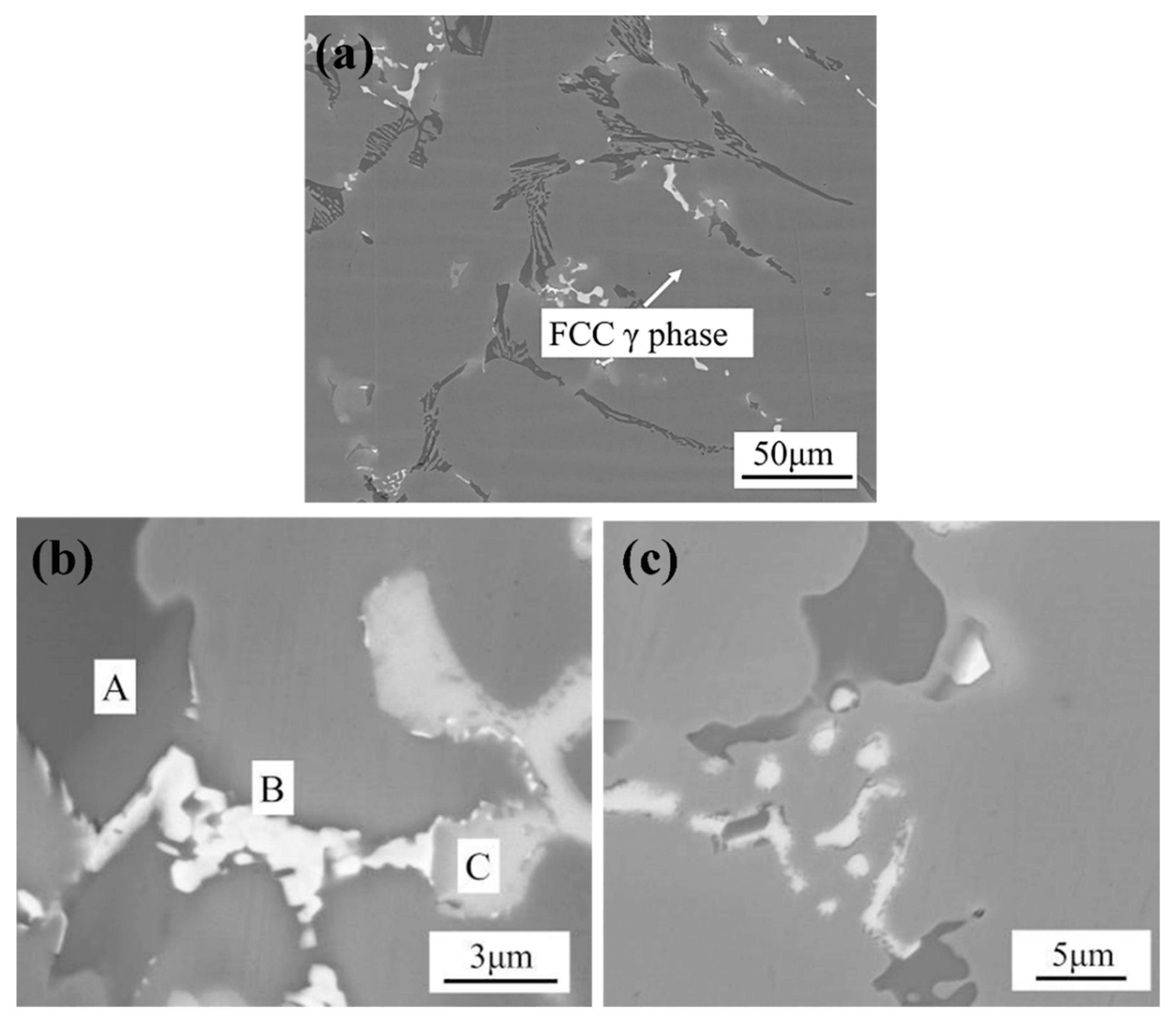
Figure 2 shows the typical microstructure of DZ40M in as-cast. It shows from Figure 2a that the carbide skeleton structure is formed in the matrix of FCC cobalt-based solid solution phase, which plays a bearing role on the alloy matrix. The EDS data show that the carbide is composed of the Phase A, B, and C. As shown in Table 2, Phase A is rich in Cr and has a small amount of Co. According to the previous study, it can be known that Phase A is the primary carbide of M7C3. M7C3 is a metastable phase with a triangular lattice of simple orthogonal structure, easy to decompose at high temperature. Phase B contains a certain amount of W, so it is presumed to be M6C carbide. M6C carbide has three kinds of morphology: granular, acicular and thin film. When it precipitates in the grain boundary or inside grain, it can improve the durability of the alloy, as shown in Figure 2c. Phase C contains a considerable amount of Ta, Ti, and Zr, which can be speculated to be MC carbide. It is the important second phase in DZ40M.
According to Sims [1], under high temperature conditions, some primary carbides in cobalt-based superalloys are prone to thermodynamic instability and decomposition, and fine secondary carbides are precipitated at the same time. The coarse primary carbides limit the plastic toughness of DZ40M, while the fine carbides can strengthen the fine crystal and ensure the plasticity of the base material. Therefore, in this paper, pre-bonding heat treatment is carried out on DZ40M at 1120 °C/5 h. 
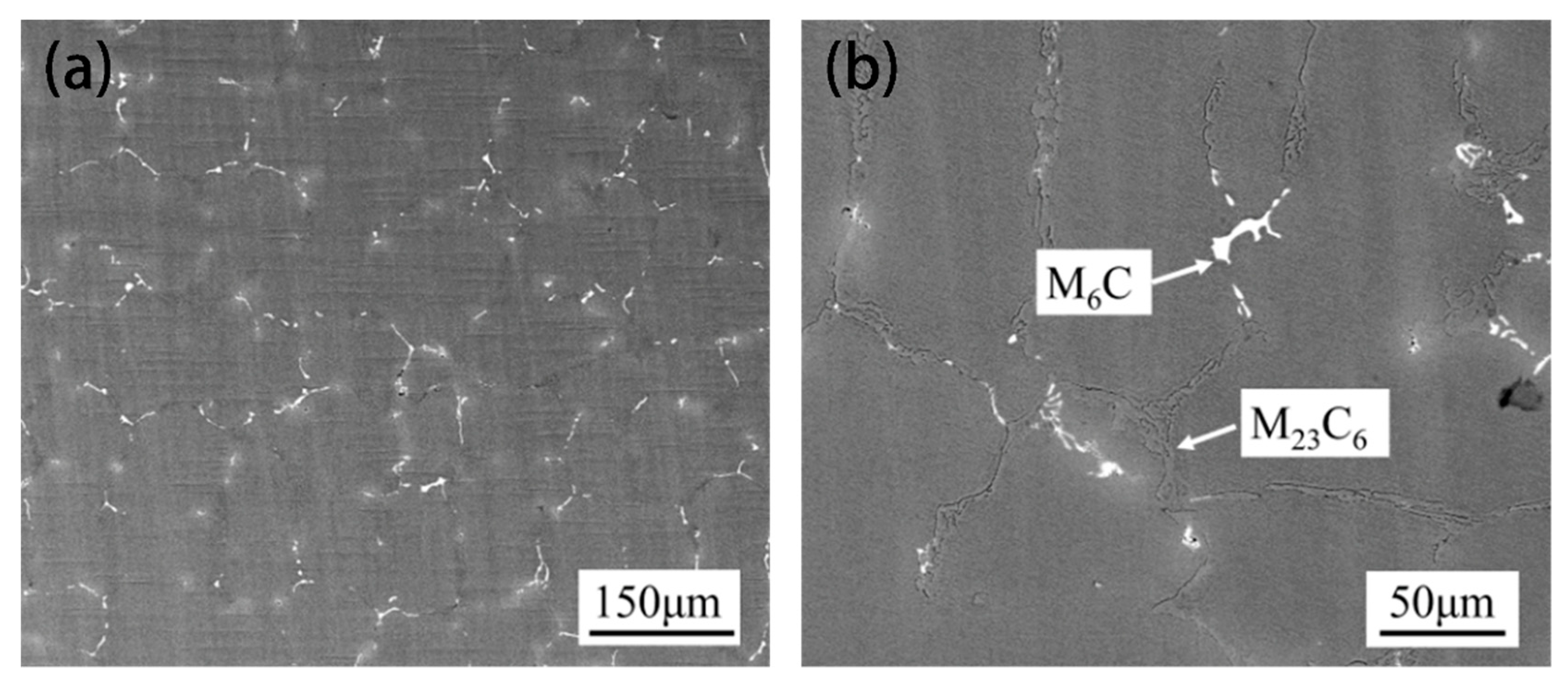
Figure 3 shows the typical microstructure of DZ40M in aged state. The coarse M7C3 carbide disappeared and there was white meshed phase in the matrix. M23C6 carbides distributed along grain boundaries and white spotty M6C carbides were observed in Figure 3b.

3.2. Typical Microstructure of TLP-Bonded Joints of DZ40M

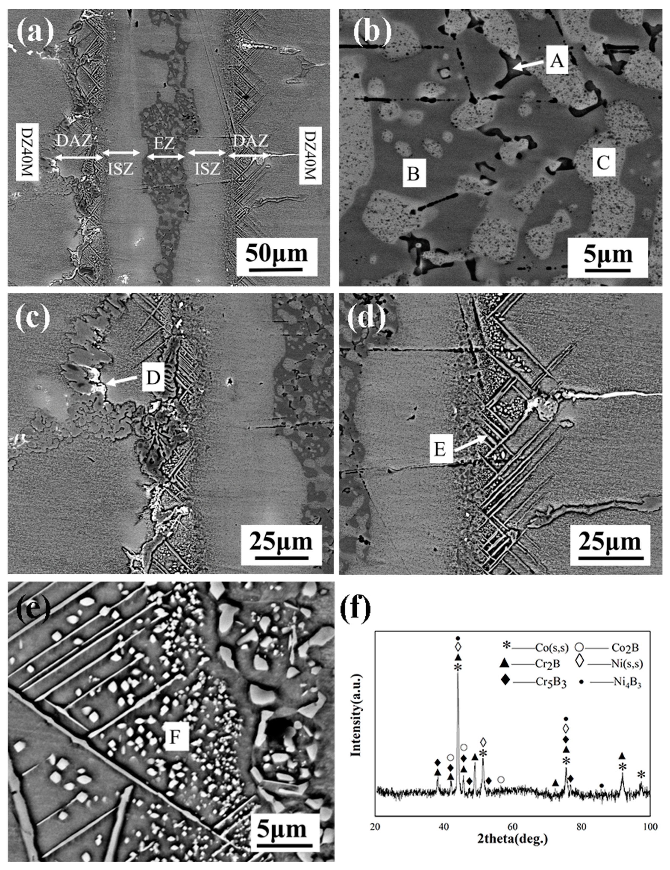
Figure 4 shows the typical microstructure of TLP-bonded joints of DZ40M at 1120 °C/30 min. From Figure 4a, a large number of eutectic structures remain in the centerline of the joint, indicating that complete isothermal solidification of the joint has not been achieved under this processing parameter. 3 typical areas can be observed, i.e., eutectic zone (EZ), isothermal solidification zone (ISZ) and diffusion affected zone (DAZ). In EZ, dark gray Phase B was observed, in which light gray Phase C and lamellar black Phase A were distributed, which exhibits a binary segregation morphology nature [12].
EDS compositional analysis of other elements (Table 3) suggests that the intermetallic phase is a Ni rich boride, and the second phase is identified as a Ni-solid solution. According to Bakhtiari [16], Phase A may be Cr-Ni rich boride, and Phase B may be Ni rich boride. The initial forming phase of the center line of the joint during cooling is a nickel-based solid solution (Phase C). Insufficient time for the diffusion of boron from the liquid interlayer to the base metal caused B element to gather near the centerline. Because the solubility of B in Ni is very low (only 0.3 at.%), B is easily precipitated in the form of borides. Near DAZ, flocculent Phase D was observed in Figure 4c. In the process of bonding nickel-based superalloy by Zhang [17], the precipitation phase of M23(C,B)6, which is similar to that of Phase D, was formed near DAZ. Therefore, it is speculated that Phase D is Cr rich boride and Co rich boride. DAZ mainly consists of acicular phase E and granular phase F. The EDS data show that the acicular phase is Co rich boride and the granular phase is Cr rich boride referring to [18]. In order to further determine the phase composition of the welded joint, X-ray diffraction tests were carried out for fractures with a connection temperature of 1120 °C and a connection time of 30 min as shown in Figure 4f. The results show that Co(s,s), Ni(s,s), Cr2B, Cr5B3, Ni4B3, and Co2B appeared in the joint. Analyzed with EDS results, Phase E may be Co2B, and Phase F may be Cr5B3 and Cr2B.
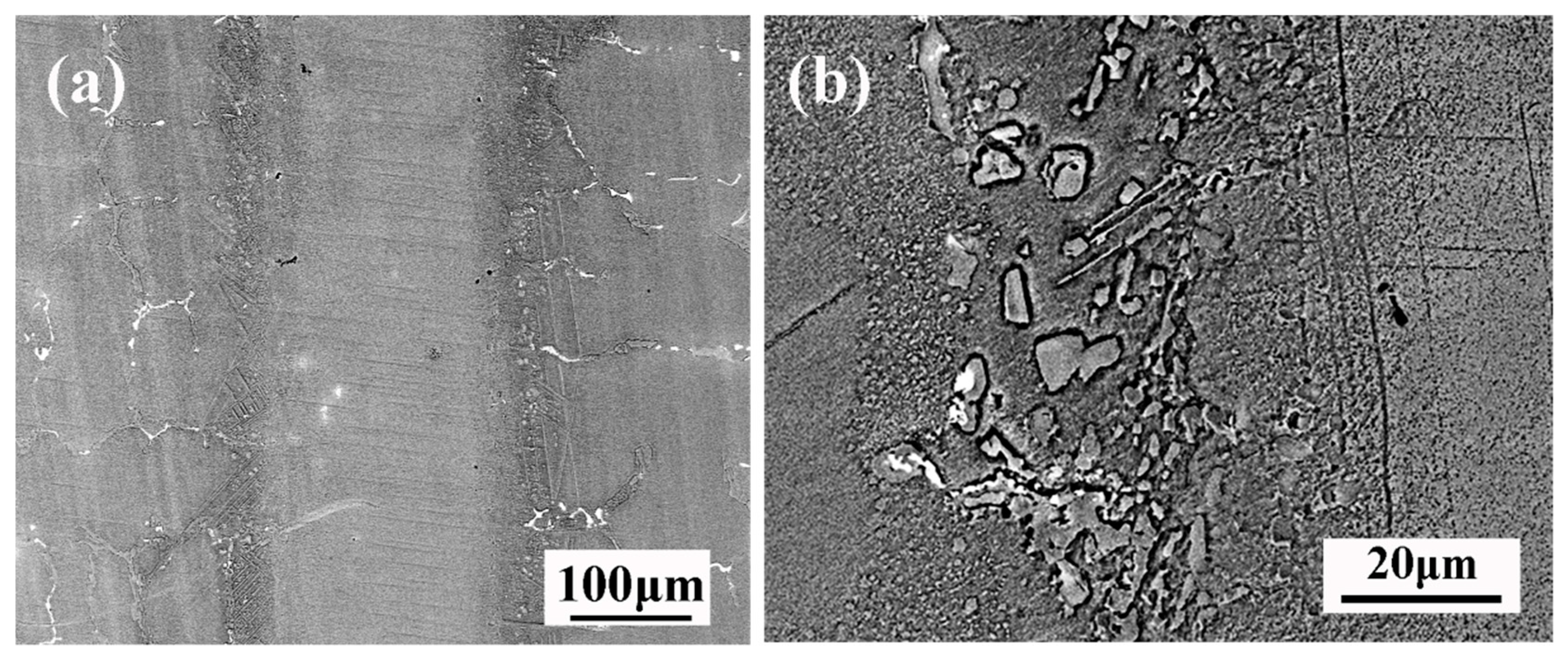
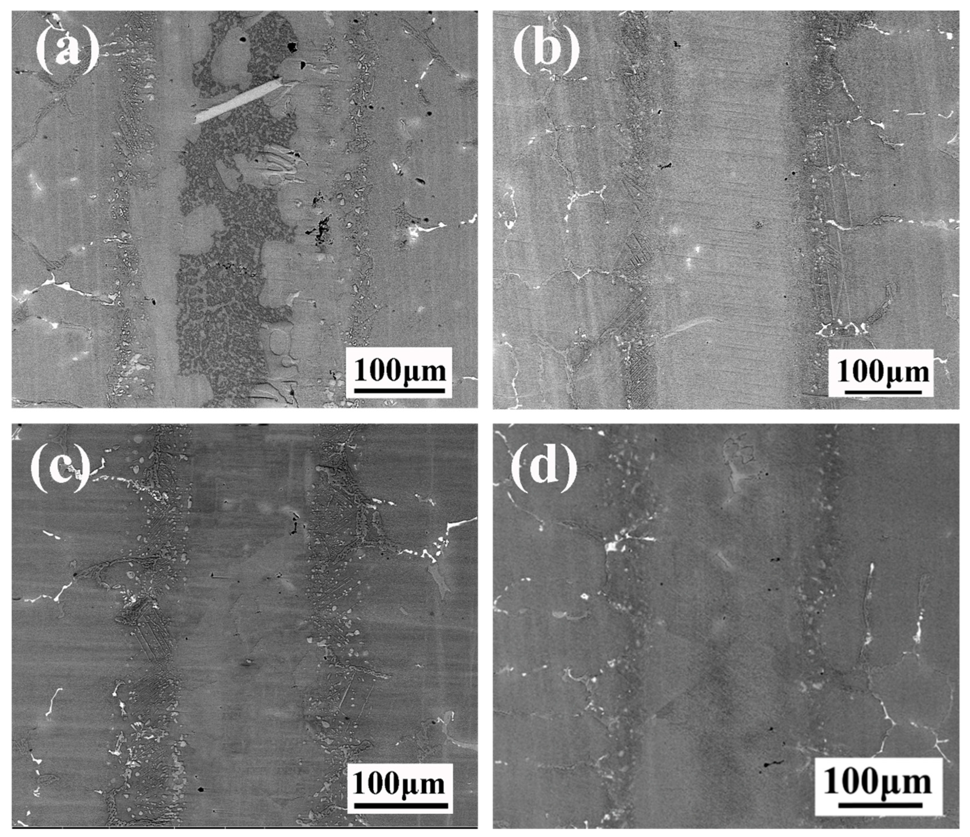
Figure 5 shows the typical microstructure of TLP-bonded joints of DZ40M at 1160 °C/30 min. From Figure 5a, there is no eutectic phase in the joint. There are mainly some granular phases in DAZ as shown in Figure 5b. According to Table 3 and relevant literature, it can be judged that the phase is Cr rich boride. This indicates that the needle phase Co rich boride gradually disappears when the bonding temperature rises to 1160 °C. The melting point of Cr-B compound is higher than that of Co-B compound indicated by the Co-B and Cr-B phase diagram, which explains why the needle phase Co rich boride gradually dissolves while the granular phase Cr rich boride still exists after the temperature rises.

3.3. Microstructural Evolution of the Brazed Joint

Figure 6 shows the microstructural evolution of TLP-bonded joints of DZ40M brazed for various durations. When the holding duration was 30 min, the commensal phase at the interface disappeared completely. With the extension of insulation time, the thickness of the diffusion zone tends to increase. The thickness of the diffusion zone is mainly related to the degree of element diffusion in the middle layer, and the diffusion distance of B dominates the formation of the diffusion zone. The diffusion coefficient is a commonly used index to measure the diffusion ability of a solute in a matrix which can be represented by the following equation [19]:
D = D 0 e x p ( Q R T )
where D0 is the diffusion constant, Q is the diffusion activation energy of solute in the matrix, R is Avogadro’s constant, and T is the temperature.
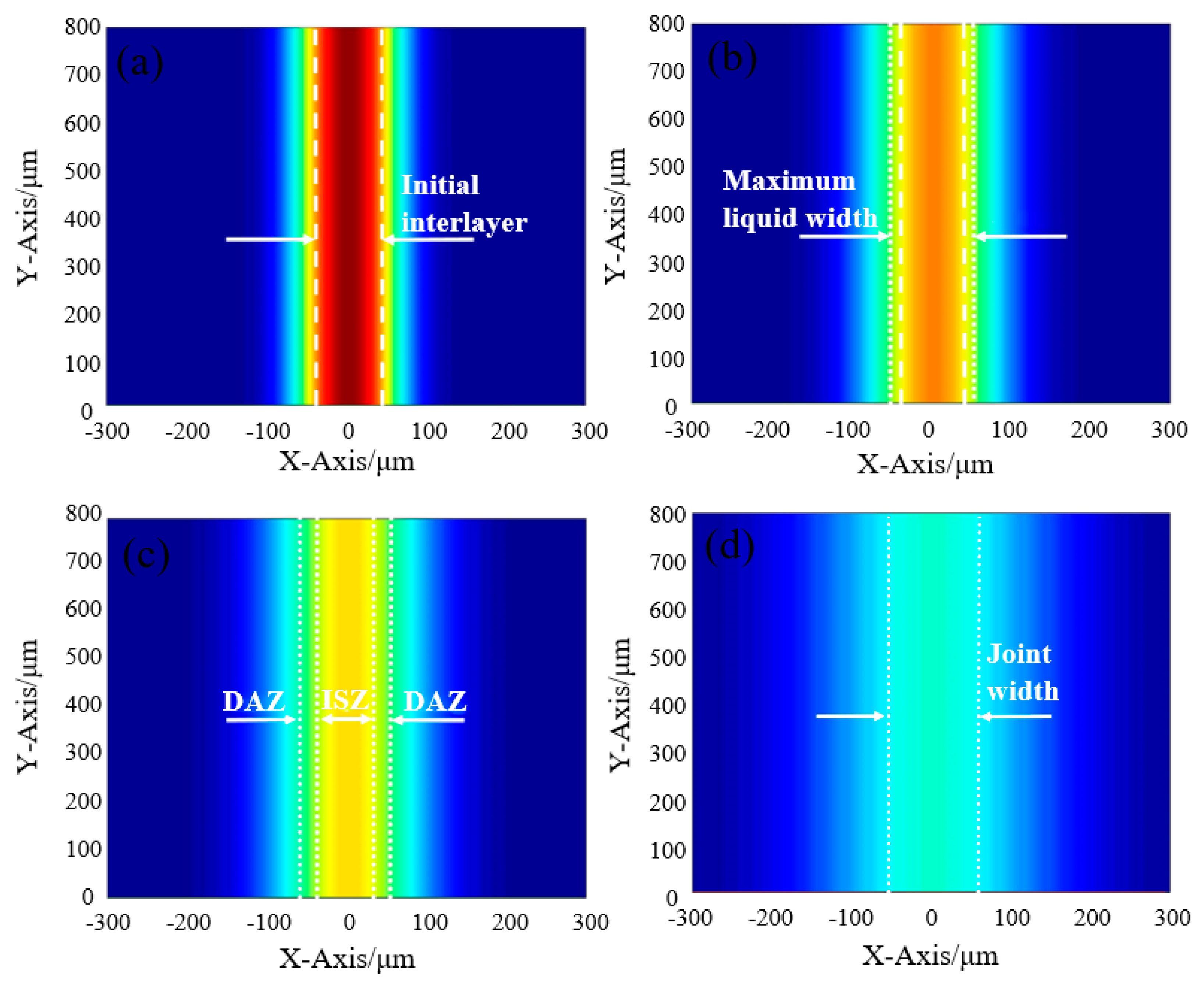
Based on the results above, we tried to propose the bonding mechanism of TLP-bonded joints of DZ40M, as shown in Figure 7. In the initial stage, interlayer the concentration of B in the interlayer was approximately uniformly distributed, but B near the base metal diffused into the base metal, resulting in a high melting point on both sides of the intermediate layer. Therefore, melting occurred first in the center of the intermediate layer, and then the liquid phase spread to both sides until the mesosphere was completely melted. Afterwards, B diffused from liquid intermediate layer to solid base material.
However, because the diffusion rate of B in the liquid phase is much higher than that in the solid phase, a large amount of B was enriched on the solid base material surface. At the solid-liquid interface, the melting point of the base material decreased and melted, and the solid-liquid boundary expanded towards the base material as shown in Figure 7b. When the content of B on the solid base material surface was not enough to reduce the melting point of the base material, the diffusion reached equilibrium and the solid-liquid interface did not expand. At this point, the intermediate layer reached the maximum liquid width. At the same time, the high melting point elements in the base material (such as Co, Cr, W, etc.) also diffused into the liquid phase, leading to the melting point of the intermediate layer liquid increasing continuously. As the intermediate layer near the base material contained more elements with high melting point and its melting point was higher, so it was preferred to solidify, as shown in Figure 7c. The solid–liquid interface advanced from the base material to the middle, isothermal solidification began, and the cobalt solidified isothermally from the faying surfaces into the melt. Boron was gradually segregated due to the low solubility of cobalt base solid solution. When the segregation of B reached a certain extent of concentration, the elements of Co and Cr will react with B to needle and spherical borides.
If the holding time was not enough, the residual liquid phase in the joint were converted into eutectic layer, as shown in Figure 7d. The microstructure of EZ can be understood by considering the solidification sequence of the remaining liquid during cooling. In the present system, on cooling, the initially formed phase is the Nickel-based solid solution in the form of dendrites growing from liquid/solid interface. During this process, B, solute elements with partition coefficient less than unity, are rejected into the liquid, enriching the liquid composition to the point where the primary solidification path intersects the moncovariant eutectic line separating solid solution and Ni boride. The solidification path then follows the eutectic line as the solid solution and nickel boride form simultaneously from the liquid by a monovariant eutectic reaction. Because the eutectic temperature of Cr-B binary eutectic system exceeded 1600 °C, it is impossible to form Cr-rich borides as the microcosmic component of binary eutectic system. The formation of nickel boride lead to the precipitation of Cr, which increased the content of Cr in the liquid phase. This is because the solubility of Cr in nickel boride (~10.11 at-%) is lower than that in solid solution (~18 at-%). Therefore, the liquid will concentrate to the ternary eutectic point and form ternary Cr boride, Ni boride, and C solid solution eutectic components at this point during the subsequent cooling process. This solidification path can be summarized as follows:
L→L + Ni(s,s)→L + Ni(s,s) + Ni borides→Ni(s,s) + Ni borides + Cr borides
If enough, the joint completed isothermal solidification as shown in Figure 7e. At this point, some Co rich boride granular phase and black secondary M23C6 precipitated phase appear in the joint.
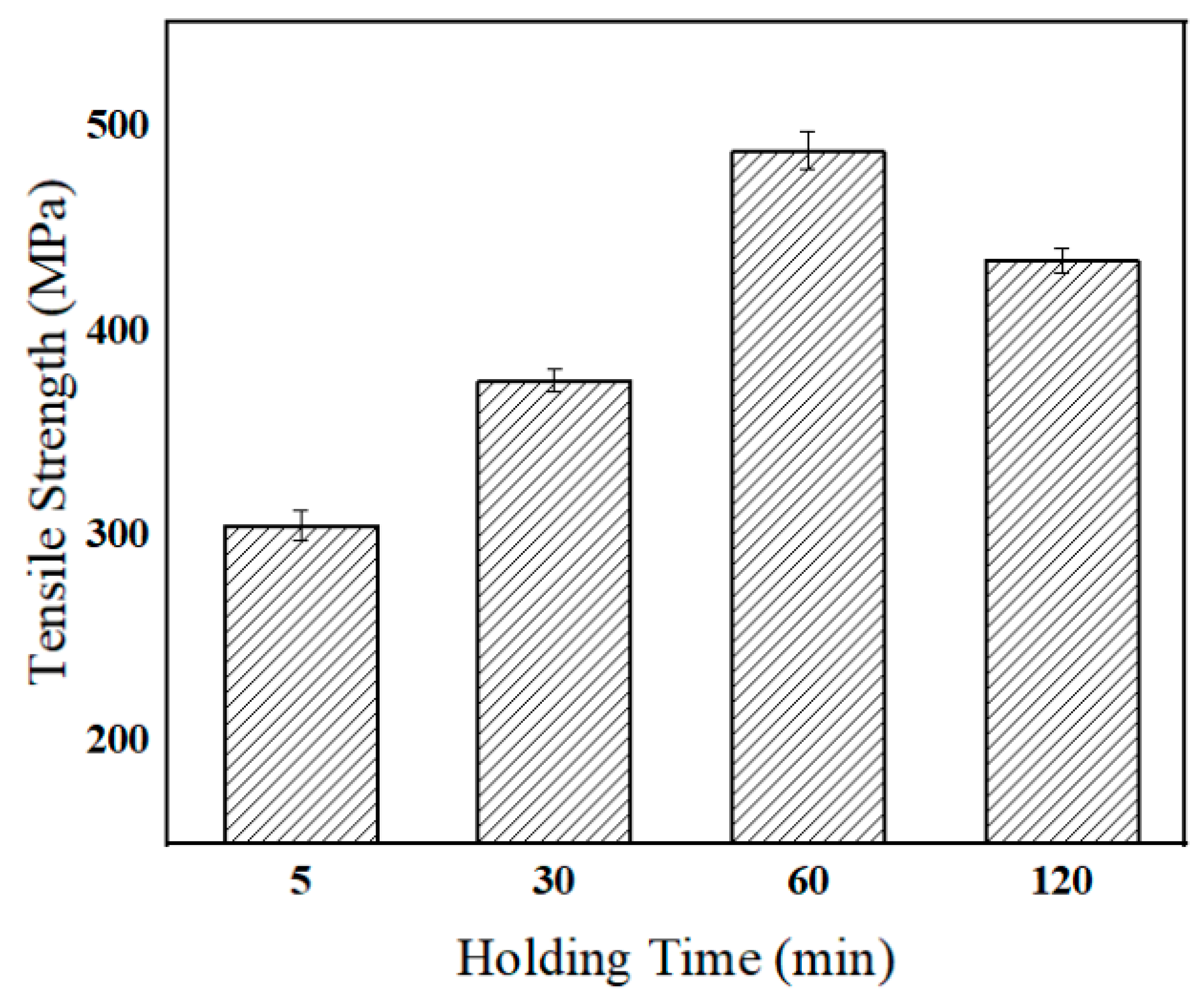
Figure 8 shows the tensile strength variation brazed with various holding duration at 1160 °C. With the increase of holding duration, the tensile strength of the joint tends to increase. When the holding duration was short, too many eutectic phases formed in the joint. When extending the holding duration, the eutectic phase gradually disappeared, which led to the increase of the joint property. When the heat preservation time was 60 min, the joint realized isothermal solidification and achieved the maximum tensile strength of 487 MPa. Theoretically speaking, the longer the holding time was, the more beneficial it was to realize the uniformity of joint tissue, and the higher tensile strength was. However, when the holding time was 120 min, the tensile strength of the joint decreased slightly to 434 MPa. This can be due to grain coarsening when the holding duration extended to 120 min, which normally weakens the joint strength [20].
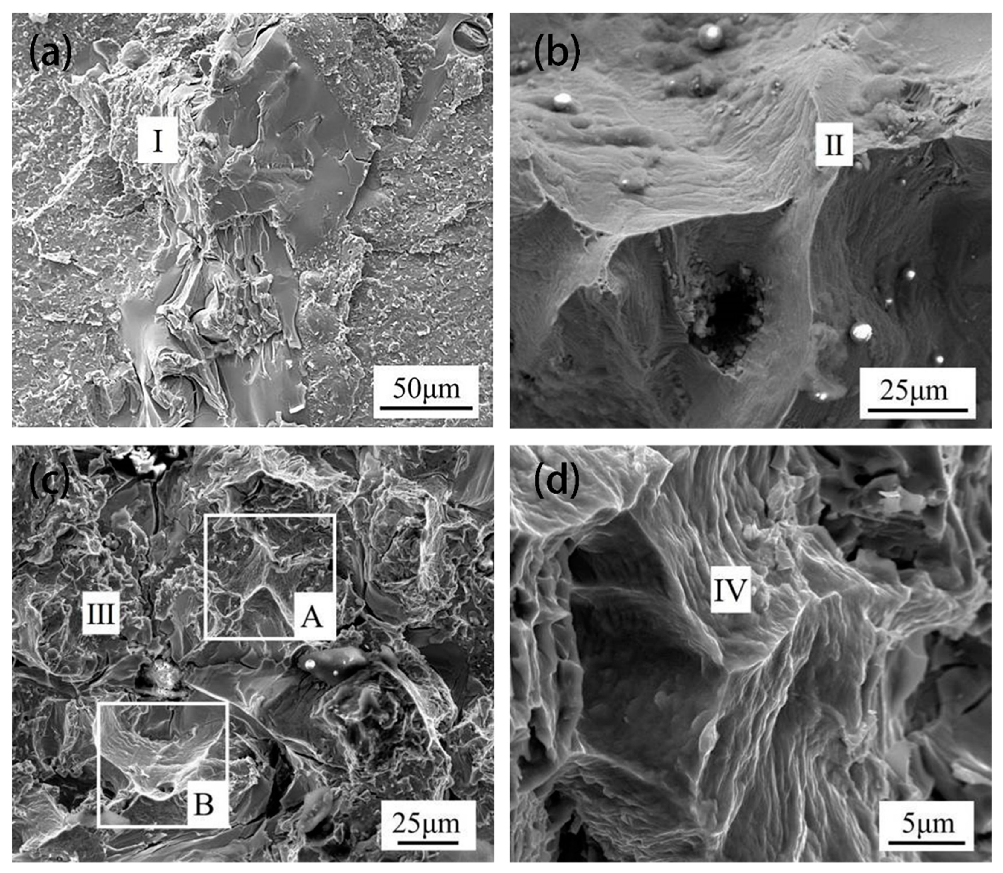
Figure 9 shows the fracture morphologies of TLP-bonded joints of DZ40M brazed with different holding duration at 1160 °C. In Figure 9a, when the holding duration was 5 min, the cleavage plane appeared, accompanied by many rock-like patterns, indicating a brittle fracture. Binary eutectic phase is the weak part in the joint indicated by the EDS data shown in Table 4. When holding for 30 min, there were many river patterns in the joint fracture, indicating that the joint was quite brittle as shown in Figure 9b. The EDS data show that there were many borides located in DAZ in the fracture, making the DAZ a weak location for the joint. A small part of dimple morphology was observed in the fracture with holding time of 60 min, as shown in Figure 9c at position A and radial patterns were observed at position B. There were rock-like patterns of intergranular fracture at other locations. It could be judged that there was a mixed ductile and brittle fracture for this case. Meanwhile, when holding for 120 min, a herringbone ridge pattern was observed in the fracture, which shows a ductile fracture nature.

3.4. Modeling Isothermal Solidification

The brittle eutectic phases with low melting point in the joint will damage the mechanical properties of the joint. Therefore, it is the focus of TLP diffusion bonding of DZ40M to determine the appropriate process to achieve complete isothermal solidification of the joint. Isothermal solidification depends on the diffusion of melting point depressant elements in the solid phase, so it is slow and usually takes several hours or even a day to complete.
In this study, the thickness and isothermal solidification time of EZ were analyzed by using a computational modeling method. To build a mathematical model, a few assumptions were made [21]:
(1) TLP bonding is a one-dimensional diffusion process and the diffusion direction is perpendicular to the interface between the middle layer and the base material.
(2) The diffusion coefficient is constant and is not affected by the change of solute concentration during bonding.
(3) The solid/liquid phase interface maintains local equilibrium and the concentration follows the concentration of the equilibrium phase diagram.
(4) The solid/liquid phase interface remains stable and flat, and no phase precipitation is formed.
(5) Since the solute diffuses slowly in the solid phase, the base material is assumed to be a semi-infinite solid.
Fick’s second law was used to analyze solute diffusion in TLP [22]:
C t = D 2 C x 2
According to initial conditions (x > 0, t = 0, C = 0) and boundary conditions (x = 0, t > 0, C = C0), the general form of solute distribution [23] can be solved:
C = A + B e r f ( X 4 D t )
where A and B are constants determined by specific boundary conditions; D is the diffusion coefficient of solute in the matrix; t stands for isothermal solidification time. For the TLP system of DZ40M, when x → ∞, erf(∞) = 1
C ( , t ) = A + B = C M
where C M is the initial solute concentration in the base metal. Let us assume that the solid/liquid interface moves to x = X(t) after time t. Hence,
C ( X ( t ) , t ) = A + B ( X ( t ) 4 D t ) = C α L
where C α L is the solute concentration of the solid phase at the solid/liquid interface. According to the hypothesis (3), the above equation is true for all values of t. Therefore, X(t) must be proportional to t1/2 [24]:
X ( t ) = k 4 D t
where k is a constant that accounts for the moving boundary. Solving Equations (3)–(6) results in the following relation:
C ( x , t ) = C M C α L C M e r f ( k ) 1 + C α L C M e r f ( k ) 1 e r f ( x 4 D t )
Since k is an unknown constant, more equations are needed to solve k. The mass balance at the solid/liquid interface gives the following relationship [24]:
( C L α C α L ) d X ( t ) d t = D ( C ( x , t ) x ) | x = X ( t )
where ( C L α C α L ) is the concentration difference between the liquid side and the solid side of the solute element and can be approximated as the concentration difference within the distance of Δx. d X ( t ) d t represents the moving speed of the solid-liquid interface. Since Δx is small, the process can be approximately uniform. D ( C ( x , t ) x ) is the diffusion flux of the solute element within Δx. Solving Equations (3)–(6) and Equation (8) results in the following relation that can be used to determine the dimensionless constant k [24]
k ( 1 + e r f ( k ) ) π e x p ( k 2 ) = C α L C M C L α C α L
From the base material composition of DZ40M, CM = 0.015%. The C L α and C α L of MPD elements can be obtained from the phase diagram, as shown in Table 5. The interface constant k was calculated, and the results are shown in 
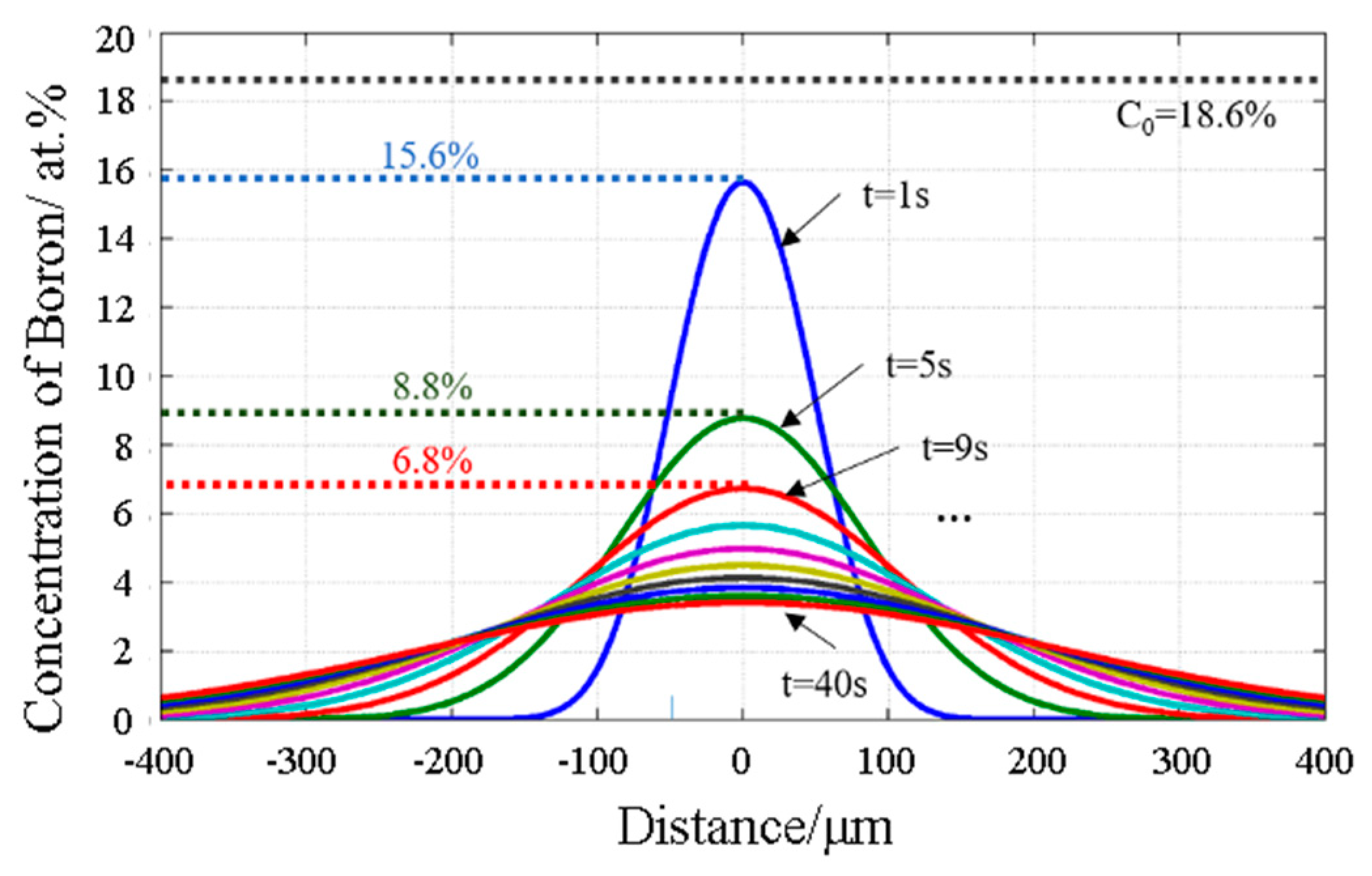
Table 5. Therefore, from Equation (7), the variation rule of the concentration distribution of B in the joint with time was obtained and the cloud diagram of B concentration change at 1160 °C is shown in Figure 10.
The concentration of B in the joint center decreased rapidly within 1–10 s. At the 100 s, B in the joint dropped to a certain value, and the scope of the diffusion layer was expanded, but homogenization was not fully realized. Figure 11 shows the concentration distribution curve of B at a time interval of 4 s at 1160 °C. The concentration of B in the joint center decreased rapidly at the initial stage of the insulation time, but decreased slowly after 20 s.
Zhou et al. [25] proposed that the maximum liquid phase width had the following relationship with the initial thickness of the mesosphere:
( 2 d m a x ) = ( 2 d 0 ) ρ 0 ρ M ( 1 + ( C 0 C L α ) C L α )
where ρ 0 and ρ M are the densities of the intermediate layer and base material; C0 is the initial concentration of B in the intermediate layer, which is 4 wt.% as shown in Table 1; 2d0 is the initial thickness of the intermediate layer and its size is 100 μm. Therefore, the maximum liquid phase thickness at 1160 °C were obtained, as shown in Table 5. Assuming that the holding time of each test was ts, the distance X(ts) moved by the solid/liquid phase interface was the thickness of ISZ, while the remaining liquid phase solidified into eutectic phase during the cooling process and formed EZ. Therefore, the thickness of EZ, WEZ, was calculated by the following equation:
W E Z = 2 ( d m a x X ( t ) ) = 2 ( d 0   ρ 0 ρ M ( 1 + ( C 0 C L α ) C L α ) k 4 D t )
where D is the diffusion coefficient, which can be represented by Equation (1). According to Khazaei et al. [26], the diffusion constant is approximately 0.14 m2/s and the diffusion activation energy is 229 KJ/mol. Therefore, the diffusion coefficient of B in cobalt-based superalloy at 1160 °C was calculated, as shown in Table 5.
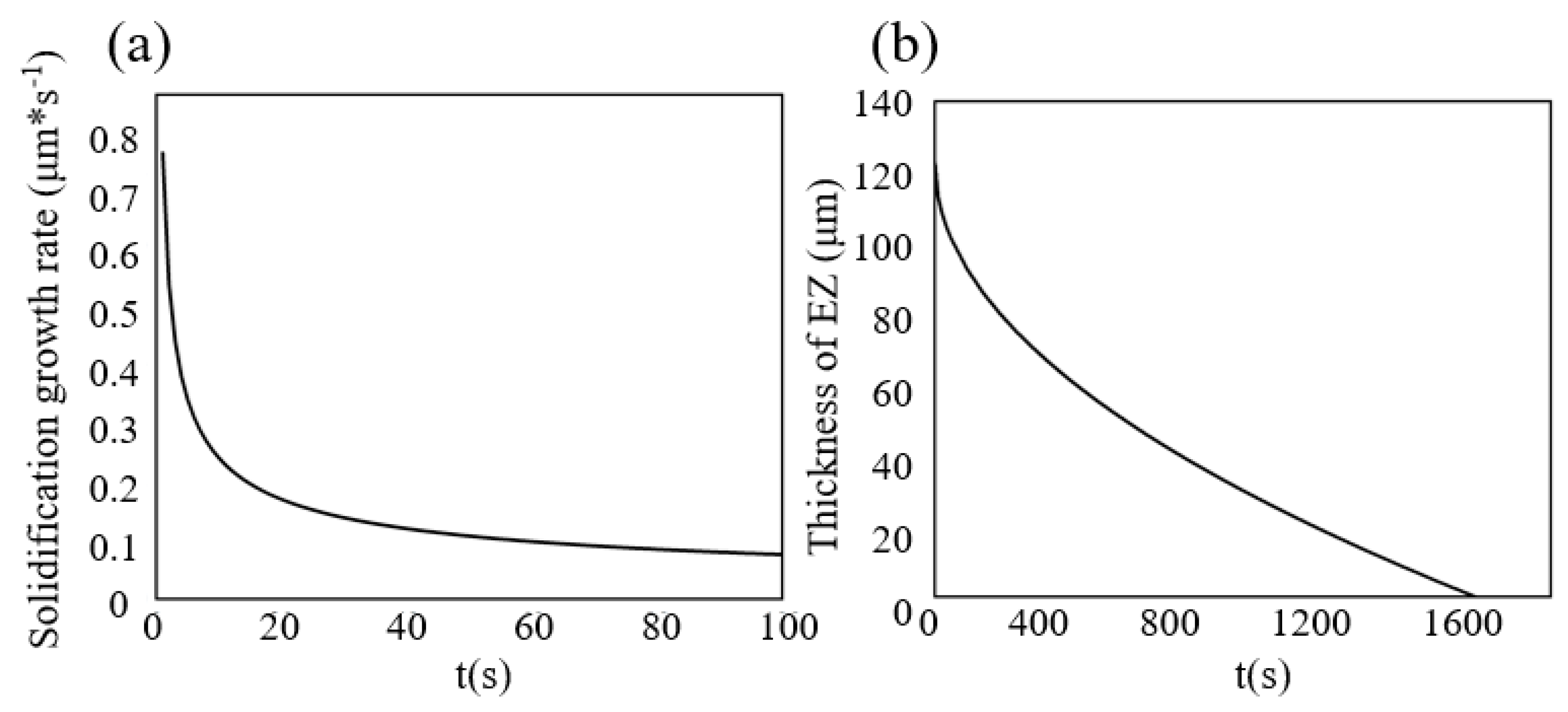
Figure 12a shows the rate of movement at the solid/liquid interface, namely the rate of isothermal solidification, obtained by taking the derivative of X(t) with respect to t.
The rate of isothermal solidification dropped to a small value after a certain time and remained stable. The variation curve of EZ thickness with holding time at 1160 °C was drawn, as shown in Figure 12b. With the increase of time, the slope absolute value of the curve was smaller, which means that the liquid phase isothermal solidification rate decreased. From Equation (6), the isothermal solidification time can be expressed as follows:
t = X 2 ( t ) 4 D k 2
According to the data in the Table 5, the time required to complete isothermal solidification of DZ40M joint were obtained. The calculation results show that when the bonding temperature was 1160 °C, the isothermal solidification time was 27.9 min. The experimental results show that there were a lot of eutectic phases in the joint when the holding time was 5 min. When the holding time was 30 min, the joint completed isothermal solidification, which indicated that the calculated results were within the reasonable range of the practical results.

4. Conclusions

TLP diffusion bonding was carried out on DZ40M by using the self-made Ni-25Cr-10Co-8W-4B (wt.%) intermediate layer. The effects of different process parameters on the interfacial microstructure and mechanical properties of the joint were investigated. The time needed for isothermal solidification completion was calculated and predicted. Main conclusions are as follows:
(1) When bonding at 1120 °C the interface was divided into four regions: EZ, ISZ, DAZ and BM. EZ mainly included Cr rich boride, Ni rich boride, and Ni-based solid solution. The phases in DAZ mainly included Co-Cr rich boride. The typical interfacial microstructure of the joint is: DZ40M/Co-Cr rich boride/(Ni, Co, Cr) s,s/Ni-based solid solution + Ni-Cr rich boride/(Ni, Co, Cr) s,s/Co-Cr rich boride/DZ40M.
(2) At 1160 °C, the eutectic phase disappeared completely, and the joint realized a complete isothermal solidification. Different holding time was achieved at 1160 °C. With the holding time extended to 30 min, complete isothermal solidification of the joint was achieved.
(3) The tensile test showed that the joints bonded at 1160 °C for 60 min possessed the highest shear strength of 487 MPa, which reached the 88.6% of base metal strength. The elimination of the eutectic phase in EZ and tiny needle-like borides in DAZ contribute to a robust bonding joint.
(4) The diffusion of B elements in the TLP process was calculated and simulated using the one-dimensional semi-infinite diffusion model. Since the concentration gradient of B reached a local equilibrium after 20 s, the isothermal solidification rate also dropped to a stable value. The completion time of isothermal solidification bonded at 1160 °C predicted by the model was 27.9 min, which was consistent with the experimental results.

Author Contributions

Conceptualization, Z.S., L.Z., and J.F.; methodology, Z.S., L.Z., and J.F.; software, X.C. and S.Z.; experimental work, X.C. and S.Z.; data curation, Z.S. and X.C.; writing—original draft preparation, X.C.; writing—review & editing, Z.S. All authors have read and agreed to the published version of the manuscript.

Funding

This research was funded by the National Natural Science Foundation of China under Grant No. 51775142 and 51805113; China Postdoctoral Science Foundation funded project under Grant No. 2020T130143 and 2018M631923.

Institutional Review Board Statement

Not applicable.

Informed Consent Statement

Not applicable.

Conflicts of Interest

The authors declare no conflict of interest.

References

  1. Sims, C.T.; Stoloff, N.S.; Hagel, W.C. Superalloys II; Materialsence: Eindhoven, The Netherlands, 1987. [Google Scholar]
  2. Chen, L.J.; Liaw, P.K.; He, Y.H.; Benson, M.L.; Blust, J.W. Tensile hold low-cycle fatigue behavior of cobalt-based HAYNES® 188 superalloy. Scr. Mater. 2001, 44, 859–865. [Google Scholar] [CrossRef]
  3. Gaumann, M.; Bezencon, C.; Canalis, P.; Kurz, W. Single-crystal laser deposition of superalloys: Processing–microstructure maps. Acta Mater. 2001, 49, 1051–1062. [Google Scholar] [CrossRef]
  4. Burke, M.A.; Swartzbeck, G.W.; Freyer, P.D. Transient Liquid Phase Bonding Repair for Advanced Turbine Blades and Vanes. U.S. Patent US6508000 B2, 21 January 2003. [Google Scholar]
  5. Thamburaj, R.; Wallace, W.; Goldak, J.A. Post-weld heat-treatment cracking in superalloys. Metall. Rev. 1983, 28, 1–22. [Google Scholar] [CrossRef]
  6. Su, C.Y.; Chou, C.P.; Wu, B.C.; Lih, W.C. Plasma transferred arc repair welding of the nickel-base superalloy IN-738LC. J. Mater. Eng. Perform. 1997, 6, 619–627. [Google Scholar] [CrossRef]
  7. Duvall, D.S.; Owczarski, W.A.; Paulonis, D.F. Methods for diffusion welding the superalloy Udimet 70. Balance 1972, 15, 18. [Google Scholar]
  8. Huang, X.; Miglietti, W. Wide gap braze repair of gas turbine blades and vanes—A review. J. Eng. Gas Turbines Power 2012, 134, 27–29. [Google Scholar] [CrossRef]
  9. Duvall, D.; Owczarski, W.; Paulonis, D. TLP bonding: A New Method for Joining Heat Resistant Alloys. Weld. J. 1974, 53, 203–214. [Google Scholar]
  10. Wikstrom, N.P.; Egbewande, A.T.; Ojo, O.A. High temperature diffusion induced liquid phase joining of a heat resistant alloy. Alloy. Compd. 2008, 460, 379–385. [Google Scholar] [CrossRef]
  11. Cao, J.; Wang, Y.F.; Song, X.G.; Li, C.; Feng, J.C. Effects of post-weld heat treatment on microstructure and mechanical properties of TLP bonded Inconel718 superalloy. Mater. Sci. Eng. A 2014, 590, 1–6. [Google Scholar] [CrossRef]
  12. Pouranvari, M.; Ekrami, A.; Kokabi, A.H. Microstructure development during transient liquid phase bonding of GTD-111 nickel-based superalloy. J. Alloy. Compd. 2008, 461, 641–647. [Google Scholar] [CrossRef]
  13. Bai, K.; Ng, F.L.; Tan, T.L.; Li, T.; Pan, D. Understanding non-parabolic solidification kinetics in Ni- -based alloys during TLP bonding via thermo-kinetic modeling. J. Alloy. Compd. 2017, 699, 1084–1094. [Google Scholar] [CrossRef]
  14. Wikstrom, N.P.; Ojo, O.A.; Chaturvedi, M.C. Influence of process parameters on microstructure of transient liquid phase bonded Inconel 738LC superalloy with Amdry DF-3 interlayer. Mater. Sci. Eng. A 2006, 417, 299–306. [Google Scholar] [CrossRef]
  15. Bakhtiari, R.; Ekrami, A.; Khan, T.I. The effect of TLP bonding temperature on microstructural and mechanical property of joints made using FSX-414 superalloy. Mater. Sci. Eng. A 2012, 546, 291–300. [Google Scholar] [CrossRef]
  16. Bakhtiari, R.; Ekrami, A. The effect of gap size on the microstructure and mechanical properties of the transient liquid phase bonded FSX-414 superalloy. Mater. Des. 2012, 40, 130–137. [Google Scholar] [CrossRef]
  17. Zhang, B.Q.; Sheng, G.; Jiao, Y.; Gao, Z.; Gong, X.; Fan, H.; Zhong, J. Precipitation and evolution of boride in diffusion affected zone of TLP joint of Mar-M247 superalloy. J. Alloy. Compd. 2017, 695, 3202–3210. [Google Scholar] [CrossRef]
  18. Nishimoto, K.; Saida, K.; Kim, D. Transient Liquid Phase Bonding of Ni-base Single Crystal Superalloy, CMSX-2. ISIJ Int. 1995, 35, 1298–1306. [Google Scholar] [CrossRef]
  19. Khazaei, B.A.; Asghari, G.; Bakhtiari, R. TLP bonding of dissimilar FSX-414/IN738 system with MBF80 interlayer: Prediction of solid/liquid interface location. Trans. Nonferrous Met. Soc. China 2014, 24, 996–1003. [Google Scholar] [CrossRef]
  20. Zhang, L.X.; Sun, Z.; Xue, Q.; Lei, M.; Tian, X.Y. Transient liquid phase bonding of IC10 single crystal with GH3039 superalloy using BNi2 interlayer: Microstructure and mechanical properties. Mater. Des. 2016, 90, 949–957. [Google Scholar] [CrossRef]
  21. Ikeuchi, K.; Zhou, Y.; Kokawa, H. Liquid- solid interface migration at grain boundary regions during transient liquid phase brazing. Metall. Mater. Trans. A 1992, 23, 2905–2915. [Google Scholar] [CrossRef]
  22. Kuntz, M.L.; Zhou, Y.; Corbin, S.F. A study of transient liquid-phase bonding of Ag-Cu using differential scanning calorimetry. Metall. Mater. Trans. A 2006, 37, 2493–2504. [Google Scholar] [CrossRef]
  23. Lindner, B. Thermodynamic and Kinetic Simulation of Transient Liquid-Phase Bonding. Available online: https://dc.uwm.edu/cgi/viewcontent.cgi?referer=https://scholar.google.co.uk/&httpsredir=1&article=1964&context=etd (accessed on 23 April 2021).
  24. Zhou, Y. Analytical modeling of isothermal solidification during transient liquid phase (TLP) bonding. J. Mater. Sci. Lett. 2001, 20, 841–844. [Google Scholar] [CrossRef]
  25. Arafin, M.A.; Medraj, M.; Turner, D.P.; Bocher, P. Transient liquid phase bonding of Inconel 718 and Inconel 625 with BNi-2: Modeling and experimental investigations. Mater. Sci. Eng. A 2007, 447, 125–133. [Google Scholar] [CrossRef]
  26. Zhou, Y.; Gale, W.F.; North, T.H. Modelling of transient liquid phase bonding. Int. Mater. Rev. 1995, 40, 181–196. [Google Scholar] [CrossRef]
Figure 1. (a)Sketches of the assemblies sample, (b) Graphite fixture for fixing sample.
Crystals 11 00479 g001
Figure 2. Typical microstructure of (a) matrix; carbide skeleton (b) carbide precipitation phase and (c) punctate M6C carbide.
Crystals 11 00479 g002
Figure 3. Typical microstructure of DZ40M in aged state: (a)integral view; (b) proeutectoid carbide.
Crystals 11 00479 g003
Figure 4. Typical microstructure of TLP-bonded joints of DZ40M at 1120 °C/30 min: (a) integral view; (b) EZ; (c) the left of DAZ; (d) the right of DAZ; (e) enlarged view of DAZ and (f) XRD pattern of the joint.
Crystals 11 00479 g004
Figure 5. Typical microstructure of TLP-bonded joints of DZ40M at 1160 °C/30 min: (a) integral view; (b) DAZ.
Crystals 11 00479 g005
Figure 6. Effect of various durations on microstructure of the joints: Integral microstructure of the joints brazed at 1160 °C for (a) 5 min;(b) 30 min;(c) 60 min; (d) 120 min.
Crystals 11 00479 g006
Figure 7. Schematic of the microstructure evolution mechanism of the brazed joint: (a) melting stage; (b) extension stage; (c) isothermal solidification stage; Typical microstructure of the brazed joint: (d) incomplete isothermal solidification; (e) complete isothermal solidification.
Crystals 11 00479 g007
Figure 8. Tensile strength of TLP joints, with holding time 5; 30; 60 and 120 min.
Crystals 11 00479 g008
Figure 9. SEM images of fractured surface of TLP joints, with holding time (a) 5; (b) 30; (c) 60 and (d) 120 min.
Crystals 11 00479 g009
Figure 10. Effect of various durations on the concentration distribution of element at 1160 °C for (a) 1 s; (b) 10 s; (c) 20 s and (d) 100 s.
Crystals 11 00479 g010
Figure 11. Effect of time on the concentration of Boron at 1160 °C.
Crystals 11 00479 g011
Figure 12. Effect of holding time on (a) the solidification growth rate and (b) the thickness of EZ.
Crystals 11 00479 g012
Table 1. Chemical composition of base alloy and used intermediate alloy (wt.%).
AlloyCoCrNiWCBTaTiZrMoAl
Base alloyBal.25.510.77.80.40.0150.30.10.20.30.9
intermediate layer1025Bal.8-4-----
Table 2. EDS chemical analysis (at.%) of different positions in Figure 2.
PositionCrNiCoWTaTiZrPhase
A85.651.229.413.70---M7C3
B30.325.9537.2026.50---M6C
C2.541.083.197.4531.9414.3839.41MC
Table 3. EDS chemical analysis (at.%) of different positions in Figure 4.
PositionNiCoCrWTiMnPhase
A31.248.6154.314.660.460.68Cr-Ni rich boride
B75.5011.3312.46-0.330.38Ni rich boride
C69.8512.0516.260.960.430.44Ni-based solid solution
D8.8539.4447.043.490.460.72Co and Cr rich boride
E12.3157.4427.202.12-0.49Co rich boride
F13.5612.9364.798.290.44-Cr rich boride
Table 4. EDS chemical analysis (at. %) of different positions in Figure 9.
PositionNiCrCoWAlPhase
I68.1416.7313.171.250.70Ni-based solution
II14.337.0966.9910.561.02Co rich boride
III11.4252.7727.297.570.93Cr and Co rich boride
IV10.1670.1214.843.701.15Cr and Co rich boride
Table 5. The result of the data required for simulation.
T/°CC/wt.%CαL/wt.%kdmax/μmD/m2·s−1tf/min
11603.1240.1770.0299761.2446.2877 × 10−1027.9
Publisher’s Note: MDPI stays neutral with regard to jurisdictional claims in published maps and institutional affiliations.

