Article

Design, Simulation, and Analysis of Optical Microring Resonators in Lithium Tantalate on Insulator

1
College of New Materials and New Energies, Shenzhen Technology University, Shenzhen 518118, China
2
School of Mechanical Engineering, Zibo Vocational Institute, Zibo 255314, China
3
School of Physics, Shandong University, Jinan 250100, China
*
Author to whom correspondence should be addressed.
Crystals 2021, 11(5), 480; https://doi.org/10.3390/cryst11050480
Submission received: 18 March 2021 / Revised: 22 April 2021 / Accepted: 24 April 2021 / Published: 25 April 2021
(This article belongs to the Special Issue New Trends in Lithium Niobate: From Bulk to Nanocrystals)

Abstract

:
In this paper we design, simulate, and analyze single-mode microring resonators in thin films of z-cut lithium tantalate. They operate at wavelengths that are approximately equal to 1.55 μm. The single-mode conditions and transmission losses of lithium tantalate waveguides are simulated for different geometric parameters and silica thicknesses. An analysis is presented on the quality factor and free spectral range of the microring resonators in lithium tantalate at contrasting radii and gap sizes. The electro-optical modulation performance is analyzed for microring resonators with a radius of 20 μm. Since they have important practical applications, the filtering characteristics of the microring resonators that contain two straight waveguides are analyzed. This work enhances the knowledge of lithium tantalate microring structures and offers guidance on the salient parameters for the fabrication of highly efficient multifunctional photonic integrated devices, such as tunable filters and modulators.

Graphical Abstract

1. Introduction

An essential component in the construction of high-density photonic integrated circuits is an optical microring resonator. This is due to its compact size, simple structure and outstanding wavelength-selective properties [1,2,3]. Such a component consists of a bus waveguide that couples to a micrometer-size ring resonator via an evanescent field. The characteristic frequency spectrum of the microring, which is dependent upon its size, is a defining factor in the transmission of a selected wavelength of light into another waveguide. The microring resonators are widely employed in the design and manufacture of optical filters [4,5,6], modulators [7,8], optical switches [9,10], optical delay lines [11], and Kerr frequency combs [12,13,14,15], etc. Multiple material systems have been used to fabricate microring resonators, such as silicon on insulator (SOI) [1,16,17,18], silicon nitride (SiN) [5,19], and lithium niobate on insulator (LNOI) [20,21,22,23].
As a material in microring resonators, lithium tantalate (LiTaO3 or simply LT) crystals have much promise because of their superior electro-optical (EO, γ33 = 27.4 pm/V), nonlinear optical, ferroelectric, and piezoelectric properties [24,25,26,27,28]. Moreover, compared with LiNbO3, LT crystals have a higher optical damage threshold (with a laser radiation induced damage of 240 MW/cm2) [29]. This enables the crystal to be used in integrated photonic chips, especially in high input power fields, such as broadband electro-optic frequency comb generation. In fact, LT crystals are already widely employed in integrated photonics and surface acoustic wave (SAW) devices [26,27,28,29]. In recent years, lithium tantalate on insulator (LTOI) is increasingly favored as the material of choice for integrated electro-optic and SAW devices [30,31,32]. This is because of its high-index contrast—which leads to a robust light guidance and a high-performance integrated device with a small footprint—that is particularly suitable for microring resonators. Due to formation of a high refractive index contrast between the ring core and the surrounding materials, a small radius microring and a large free spectral range (FSR) are possible. LTOI also offers the opportunity of electronically controlling the transmission spectrum, via the efficient EO effects of LT crystals that can enable extreme compactness and ultra-fast switching and modulation. Moreover, the integration of lithium tantalate thin films onto silicon substrates enables LTOI to be compatible with a complementary metal-oxide-semiconductor (CMOS); this could lead to significantly decreased research costs and an extensive increase in production [30]. However, to our knowledge, microring resonators in LTOI have not been reported elsewhere in the literature.
In this paper, we present the design, simulation and analysis of a single-mode microring resonator that is based on LTOI. By use of a full-vectorial finite difference method, we offer a study of the single-mode conditions and transmission losses of LT waveguides that contains different geometric parameters and SiO2 cladding layer thicknesses. In order to obtain improved wavelength filtering effects, both the radius of the microring (R) and the size of the gap between the ring and linear waveguides have optimized values in the 2.5-dimension variational finite-difference time-domain (varFDTD) using Lumerical’s MODE solutions software. Such parameters have direct effects on the quality factor (known as the Q factor) and FSR. The electro-optic modulated microring resonators, which are significant in practical applications, are also described.

2. Device Description

From top to bottom, the LTOI presented in this work contains a z-cut LT thin film, a SiO2 cladding layer, and a Si substrate. The research center of NANOLN Corporation, for example, could easily perform such a fabrication. The schematic for this microring resonator is shown in Figure 1. The optical device consists of a ring resonator coupled to a straight waveguide channel, both of which are made from the z-cut LT thin film. If the optical signal is resonant within the ring, a coupling occurs from the channel into the cavity. To calculate the single-mode conditions, and the propagation losses of the LT waveguides, a full-vectorial finite-difference method is employed. Computation of the Q factor and FSR of the simulation is achieved with a varFDTD method that uses perfectly matched layers (PML) boundary conditions [33]. The varFDTD is the direct space and the time solution for solving Maxwell’s equations in complex geometrical shapes. It is based on collapsing a 3D geometry into a 2D effective indices set, which allows 2D FDTD to be used to solve this problem. By performing Fourier transforms, results such as normalized transmission, far field projection, and Poynting vector can be obtained [23].

3. Results and Discussion

To prevent signal distortion during the transmission, single-mode conditions within the waveguide are required. To achieve this necessity, a suitable waveguide thickness (h) and width (w) are needed. The refractive indexes for the LiTaO3, the SiO2 cladding layer, and the Si substrate at the simulation wavelength of 1.55 μm are shown in Table 1. As shown in Figure 2a, via a simulation we determine the curve of the effective refractive index on changing the waveguide thickness (using a waveguide width of 0.7 µm and operating at the wavelength λ = 1.55 µm). The single-mode conditions of the transverse electric (TE) and transverse magnetic (TM) modes are 0.77 μm and 0.78 μm, respectively. The thickness of the LT film is set to 0.5 µm to ensure the single-mode condition in the simulation.
In addition, the waveguide width also needs to be optimized. On setting the waveguide thickness to its optimal value of 0.5 µm, we calculate the effective refractive index as a function of the LT ridge waveguide width—as shown in Figure 2b. For the LT ridge waveguide, the first order TE and TM modes first appear for the LT thicknesses at 0.92 μm and 0.97 μm, respectively. To guarantee the single-mode condition, a waveguide width of 0.7 µm is chosen. This is because only the TM modes can employ the coefficient γ33 in a z-cut LT crystal, the TM modes are calculated in the following calculation.
Since the thickness of the SiO2 layer (T) affects the transmission losses of the LT waveguides, we simulate these losses for different layer thicknesses. The results are illustrated in Figure 3. They show that the transmission losses decrease with increasing thickness of the SiO2 layer. The Au films in the LT-SiO2-Au structure are used as the electrodes in the electro-optic modulator. At the same thickness of the SiO2 layer, the losses for a LT-SiO2-Au structure (when the Au film thickness is 0.3 µm) are less than those of LT-SiO2-Si. This is because electromagnetic fields are more likely to leak into the Si substrate (during the light propagation) since the refractive index of silicon (nSi) is the highest among the relevant materials. Therefore, inclusion of the gold film enables greater isolation of the fields from the surroundings and, thus, the leakage of light is more preventable. In addition, the waveguide light mode has contact with the Au films during its propagation, which enables the excitation of the surface plasmons, and increases the absorption losses. But in comparison to the leakage loss, the absorption loss is much lower. When the thickness of the SiO2 layer is greater than 2 µm, the losses from the LT waveguide are negligible. Therefore, the optimal value for the SiO2 layer thickness is set at 2 µm.
For our purposes, the key parameters of the optical device are the radius of the microring and the gap between the ring and linear waveguides. These factors are used to determine the Q factor and FSR of the microring resonators. We calculate these parameters for differing microring radii and gap sizes, while operating at around λ = 1.55 µm. As shown in Figure 4a, when the microring radius is lower than 10 µm, the Q factor becomes rapidly enhanced with increasing radius size. However, the Q factor value is essentially unchanged when the radius is greater than 20 µm. The Q factor is increased with larger gaps. The propagation losses of the microrings are caused by the following factors: (1) the electromagnetic fields leak into the Si substrate when the light propagates through the resonators (but lower than 2.5 × 10⁻² dB/cm with a SiO2 layer thickness of 2 µm), and (2) the radiative losses within the curved waveguide (which is roughly 8 × 10⁻² dB/cm with a bending radius of 20 μm). Additionally, in practice, the structures will contain a residual roughness for the etching surface of the waveguide which causes scattering losses. When the radius is greater than 20 μm, the Q-factor may decrease as the radius increases due to the existence of scattering loss. As shown in Figure 4b, the FSR for TM mode reach a maximum at a radius of 5 µm and then it decreases with increasing ring radius. Figure 5 shows the transmission spectrum of a microring with a radius of 20 μm for the TM mode.
The characterization of the electronic tuning of the optical resonances in the microring resonators is determined using optical transmission simulations. As we have seen, the schematic of the electrode structure for the microring resonator is shown in Figure 1. This depicts an LT microring resonator that is embedded within a SiO2 layer, with the electrodes positioned either side (above and below) the SiO2 layer. The tuning range for the microring resonators is highly dependent upon the strength of the EO effects. The result of a simulation for the optical field is shown in Figure 6. Here, the LT waveguide has a thickness of 0.5 µm, a width of 0.7 µm, and a SiO2 layer thickness of 2 µm. As seen in Figure 6, most of the optical power (TM mode) is confined within the electro-optic active material, i.e., the LT core. Electrodes can be designed, and positioned close to the waveguides, that circumvent substantially larger optical transmission losses.
The variation of extraordinary refractive index of LT (Δne) after application of an electrostatic field is expressed as:
Δ n e = 1 2 n e 3 γ 33 E z
where ne is the extraordinary refractive index of LT. When the electrostatic field intensity, Ez, is 1 V/μm, the variation in the refractive index at λ = 1.55 µm is Δne = 1.3 × 10⁻⁴.
Observation of the EO effect requires an electric field to be applied between the electrodes. Figure 7 shows the EO modulation characteristic spectra at different DC voltages (using a TM mode) for such a situation. A greater resonance wavelength shift is exhibited for increasing electric field strengths. In detail, the resonance wavelength displacement is 80 pm, 160 pm, 240 pm, and 320 pm when the electric field intensity is set at 1 V/µm, 2 V/µm, 3 V/µm, and 4 V/µm, respectively.
Tunable filtering is an important application for the LT microring because it is an attractive candidate for a narrower bandwidth integrated optical filter for the wavelength division multiplexing (WDM) systems. Figure 8 shows the transmission spectra for the drop port of the LT microring filters, at different electric field intensities, with a double straight waveguide structure. The structure of the microring filter is shown in the inset of Figure 8. The resonance wavelength shift is 320 pm in an electric field intensity of 4 V/μm.
Figure 9 shows the electrostatic field strength when a voltage of 1V is applied to the electrodes. As we can see, the attainable electric field in the LT film is relatively weak; this is because the adjacent cladding materials exhibit a dielectric constant, ε, that is one order of magnitude smaller, i.e., εSiO2 = 3.9 and εLT = 42.8 [34]. Hence, the electric field strength in the LT thin film is significantly smaller than the SiO2 layer. The electrostatic field intensity in the z-direction (Ez) is 0.033 V/μm when close to the center of the waveguide, for cases when a voltage of 1V is applied to the electrodes (for which h = 0.5 µm, w = 0.7 µm, and T = 2 µm). The problem of the relatively small Ez field in the LT waveguides can be improved by changing the geometry of the electrodes or by using a x- or y-cut configuration. For example, using an incompletely etched waveguide structure (leaving a certain thickness of slab across the chip) on the x- or y-cut LTOI enables a relatively strong electric field strength in the LT waveguide [35,36]. However, compared with the microrings on the z-cut LTOI, the microrings on the x- or y-cut LTOI can apply an electric field to only part of the microring, so the length of the effective electro-optic modulation is shorter [15,35,36]. Assuming that there is a uniform electric field in the waveguide, and the electric field strength is equal to that at the center of the waveguide. The EO tunability of LTOI microring is about 2.6 pm/V in this work. Table 2 reports the comparison of the results of different types for LiNbO3 and LiTaO3 tunable microrings. As we can infer from this table, LTOI photonics provides a promising approach for tunable microring resonators. The geometry of the electrodes, and the cavity-photon lifetime of the resonator, will affect the modulation rate of the microring [35,37,38]. Electrode design is especially crucial for modulators, especially for high bit rate modulation formats. For example, a top electrode with a ring structure can achieve a relatively high modulation rate [37]. A further study of the influence of the electrode geometry on the modulation rate will be provided in future work.

4. Conclusions

In this paper we design, simulate, and analyze a single-mode microring resonator that is based on LTOI. The waveguide width and the LT film thickness are optimized to ensure single-mode conditions. The propagation losses of the LT waveguides at different SiO2 layer thickness are analyzed and discussed. The effects on the Q factor and the FSR that arise due a change in the ring radius and the gap size between the ring and linear waveguides are quantified and then discussed. It is also determined that the Q factor increases when the ring radius increases, the Q factor stabilizes when the radius is greater than 20 µm, and FSR decreases with increasing radius. We simulate and discuss the electro-optic tunable microring resonator, which is a highly significant topic because of its practical applications. For example, an EO modulation spectrum of the microring (with a gap = 0.4 µm and a radius = 20 µm) is produced that is displaced by 80 pm when an electric field intensity of 1 V/μm is applied. We expect that our results and analysis will provide useful guidance to laboratory works on microring resonator in LTOI.

Author Contributions

Conceptualization, B.X.; methodology, B.X.; validation, S.Y. and S.J.; investigation, S.Y., H.H. and B.X.; data curation, S.Y.; writing—original draft preparation, S.Y.; writing—review and editing, B.X., G.C., and S.R.; supervision, B.X.; funding acquisition, B.X. All authors have read and agreed to the published version of the manuscript.

Funding

This work was supported by the Shenzhen Science and Technology Planning (NO. JCYJ20190813103207106), the Project of Youth Innovative Talents in Higher Education Institutions of Guangdong (NO. 2018KQNCX399), and the National Natural Science Foundation of China (NO. 61935014).

Conflicts of Interest

The authors declare no conflict of interest.

References

  1. Bogaerts, W.; De Heyn, P.; Van Vaerenbergh, T.; De Vos, K.; Selvaraja, S.K.; Claes, T.; Dumon, P.; Bienstman, P.; Van Thourhout, D.; Baets, R. Silicon microring resonators. Laser Photonics Rev. 2012, 6, 47–73. [Google Scholar] [CrossRef]
  2. Vahala, K.J. Optical microcavities. Nature 2003, 424, 839–846. [Google Scholar] [CrossRef] [PubMed]
  3. Han, H.; Xiang, B. Simulation and analysis of electro-optic tunable microring resonators in silicon thin film on lithium niobate. Sic. Rep. 2019, 9, 6302. [Google Scholar] [CrossRef] [PubMed]
  4. Mak, J.C.C.; Sacher, W.D.; Xue, T.Y.; Mikkelsen, J.C.; Yong, Z.; Poon, J.K.S. Automatic resonance alignment of high-order microring filters. IEEE J. Quantum. Elect. 2015, 51, 1–11. [Google Scholar] [CrossRef]
  5. Barwicz, T.; Popovic, M.A.; Rakich, P.T.; Watts, M.R.; Haus, H.A.; Ippen, E.P.; Smith, H.I. Microring-resonator-based add-drop filters in SiN: Fabrication and analysis. Opt. Express 2004, 12, 1437–1442. [Google Scholar] [CrossRef]
  6. Chen, G.P.; Jiang, C. Reverse design of microring resonator channel dropping filters. Results Phys. 2020, 19, 103380. [Google Scholar] [CrossRef]
  7. Xu, Q.F.; Manipatruni, S.; Schmidt, B.; Shakya, J.; Lipson, M. 12.5 Gbit/s carrier-injection-based silicon micro-ring silicon modulators. Opt. Express 2007, 15, 430–436. [Google Scholar] [CrossRef] [Green Version]
  8. Cao, W.; Hagan, D.; Thomson, D.J.; Nedeljkovic, M.; Littlejohns, C.G.; Knights, A.; Alam, S.U.; Wang, J.J.; Gardes, F.; Zhang, W.W.; et al. High-speed silicon modulators for the 2 μm wavelength band. Optica 2018, 5, 1055–1062. [Google Scholar] [CrossRef]
  9. Wang, Y.H.; Lv, P.; Zhang, Y.L.; Song, M.X.; Liu, C.L.; Wang, G.F.; Wang, C.X.; Qin, Z.K. Analysis of characteristics of a parallel channel microring resonator electro-optic switch array. Optik 2018, 165, 332–340. [Google Scholar] [CrossRef]
  10. Emelett, S.J.; Soref, R. Design and simulation of silicon microring optical routing switches. J. Lightwave Technol. 2005, 23, 1800–1807. [Google Scholar] [CrossRef]
  11. Cardenas, J.; Foster, M.A.; Sherwood-Droz, N.; Poitras, C.B.; Lira, H.L.R.; Zhang, B.B.; Gaeta, A.L.; Khurgin, J.B.; Morton, P.; Lipson, M. Wide-bandwidth continuously tunable optical delay line using silicon microring resonators. Opt. Express 2010, 18, 26525–26534. [Google Scholar] [CrossRef] [PubMed] [Green Version]
  12. Zhang, M.; Buscaino, B.; Wang, C.; Shams-Ansari, A.; Reimer, C.; Zhu, R.R.; Kahn, J.M.; Loncar, M. Broadband electro-optic frequency comb generation in a lithium niobate microring resonator. Nature 2019, 568, 373–377. [Google Scholar] [CrossRef] [PubMed]
  13. Kovach, A.; Chen, D.Y.; He, J.H.; Choi, H.; Dogan, A.H.; Ghasemkhani, M.; Taheri, H.; Armani, A.M. Emerging material systems for integrated optical Kerr frequency combs. Adv. Opt. Photonics 2020, 12, 135–222. [Google Scholar] [CrossRef] [Green Version]
  14. Fujii, S.; Tanabe, T. Dispersion engineering and measurement of whispering gallery mode microresonator for Kerr frequency comb generation. Nanophotonics 2020, 9, 1087–1104. [Google Scholar] [CrossRef] [Green Version]
  15. Wang, C.; Zhang, M.; Yu, M.J.; Zhu, R.R.; Hu, H.; Loncar, M. Monolithic lithium niobate photonic circuits for Kerr frequency comb generation and modulation. Nat. Commun. 2019, 10, 978. [Google Scholar] [CrossRef]
  16. Reed, G.T.; Mashanovich, G.; Gardes, F.Y.; Thomson, D.J. Silicon optical modulators. Nat. Photonics 2010, 4, 518–526. [Google Scholar] [CrossRef] [Green Version]
  17. Xu, Q.F.; Fattal, D.; Beausoleil, R.G. Silicon microring resonators with 1.5-µm radius. Opt. Express 2008, 16, 4309–4315. [Google Scholar] [CrossRef] [Green Version]
  18. Mi, G.C.; Horvath, C.; Aktary, M.; Van, V. Silicon microring refractometric sensor for atmospheric CO2 gas monitoring. Opt. Express 2016, 24, 1773–1780. [Google Scholar] [CrossRef] [PubMed]
  19. Zamora, V.; Lutzow, P.; Weiland, M.; Pergande, D. Investigation of cascaded SiN microring resonators at 1.3 µm and 1.5 µm. Opt. Express 2013, 21, 27550–27557. [Google Scholar] [CrossRef]
  20. Guarino, A.; Poberaj, G.; Rezzonico, D.; Degl’Innocenti, R.; Gunter, P. Electro-optically tunable microring resonators in lithium niobate. Nat. Photonics 2007, 1, 407–410. [Google Scholar] [CrossRef]
  21. Lu, J.J.; Surya, J.B.; Liu, X.W.; Bruch, A.W.; Gong, Z.; Xu, Y.T.; Tang, H.X. Periodically poled thin-film lithium niobate microring resonators with a second-harmonic generation efficiency of 250,000%/W. Optica 2019, 6, 1455–1460. [Google Scholar] [CrossRef] [Green Version]
  22. Yu, M.J.; Okawachi, Y.; Cheng, R.; Wang, C.; Zhang, M.; Gaeta, A.L.; Loncar, M. Raman lasing and soliton mode-locking in lithium niobate microresonators. Light. Sci. Appl. 2020, 9, 9. [Google Scholar] [CrossRef] [Green Version]
  23. Han, H.P.; Xiang, B.X.; Zhang, J.L. Simulation and analysis of single-mode microring resonators in lithium niobate thin films. Crystals 2018, 8, 342. [Google Scholar] [CrossRef] [Green Version]
  24. Casson, J.L.; Gahagan, K.T.; Scrymgeour, D.A.; Jain, R.K.; Robinson, J.M.; Gopalan, V.; Sander, R.K. Electro-optic coefficients of lithium tantalate at near-infrared wavelengths. J. Opt. Soc. Am. B 2004, 21, 1948–1952. [Google Scholar] [CrossRef] [Green Version]
  25. Barie, N.; Wessa, T.; Bruns, M.; Rapp, M. Love waves in SiO2 layers on STW-resonators based on LiTaO3. Talanta 2004, 62, 71–79. [Google Scholar] [CrossRef]
  26. Lobino, M.; Marshall, G.D.; Xiong, C.; Clark, A.S.; Bonneau, D.; Natarajan, C.M.; Tanner, M.G.; Hadfield, R.H.; Dorenbos, S.N.; Zijlstra, T.; et al. Correlated photon-pair generation in a periodically poled MgO doped stoichiometric lithium tantalate reverse proton exchanged waveguide. Appl. Phys. Lett. 2011, 99, 081110. [Google Scholar] [CrossRef] [Green Version]
  27. Kawachi, O.; Mineyoshi, S.; Endoh, G.; Ueda, M.; Ikata, O.; Hashimoto, K.; Yamaguchi, M. Optimal cut for leaky SAW on LiTaO3 for high performance resonators and filters. IEEE Trans. Ultrason. Ferroelectr. Freq. Control 2001, 48, 1442–1448. [Google Scholar] [CrossRef] [PubMed]
  28. Takai, T.; Iwamoto, H.; Takamine, Y.; Yamazaki, H.; Fuyutsume, T.; Kyoya, H.; Nakao, T.; Kando, H.; Hiramoto, M.; Toi, T.; et al. High performance SAW resonator on new mutilayered substrate using LiTaO3 crystal. IEEE Trans. Ultrason. Ferroelectr. Freq. Control 2017, 64, 1382–1389. [Google Scholar] [CrossRef]
  29. Yan, X.S.; Liu, Y.A.; Ge, L.C.; Zhu, B.; Wu, J.W.; Chen, Y.P.; Chen, X.F. High optical damage threshold on-chip lithium tantalate microdisk resonator. Opt. Lett. 2020, 45, 4100–4103. [Google Scholar] [CrossRef]
  30. Yan, Y.Q.; Huang, K.; Zhou, H.Y.; Zhao, X.M.; Li, W.Q.; Li, Z.X.; Yi, A.L.; Huang, H.; Lin, J.J.; Zhang, S.B.; et al. Wafer-scale fabrication of 42° rotated Y-cut LiTaO3-on-insulator (LTOI) substrate for a SAW resonator. ACS Appl. Electron. Mater. 2019, 1, 1660–1666. [Google Scholar] [CrossRef]
  31. Tauzin, A.; Dechamp, J.; Madeira, F.; Mazen, F.; Zussy, M.; Deguet, C.; Clavelier, L.; Moulet, J.S.; Richtarch, C.; Akatsu, T.; et al. 3-inch single-crystal LiTaO3 films onto metallic electrode using Smart CutTM technology. Electron. Lett. 2008, 44, 822–824. [Google Scholar] [CrossRef]
  32. Ma, C.D.; Lu, F.; Xu, B.; Fan, R.R. Visualized strain profile in the process of crystal ion slicing of LiTaO3. J. Phys. D Appl. Phys. 2016, 49, 205301. [Google Scholar] [CrossRef]
  33. Berenger, J.P. A perfectly matched layer for the absorption of electromagnetic waves. J. Comput. Phys. 1994, 114, 185–200. [Google Scholar] [CrossRef]
  34. Smith, R.T.; Welsh, F.S. Temperature dependence of the elastic, piezoelectric, and dielectric constants of lithium tantalate and lithium niobate. J. Appl. Phys. 1971, 42, 2219–2230. [Google Scholar] [CrossRef]
  35. Wang, C.; Zhang, M.; Stern, B.; Lipson, M.; Lončar, M. Nanophotonic lithium niobate electro-optic modulators. Opt. Express 2018, 26, 1547–1555. [Google Scholar] [CrossRef] [PubMed] [Green Version]
  36. Mahmoud, M.; Cai, L.; Bottenfield, C.; Piazza, G. Lithium niobate electro-optic racetrack modulator etched in Y-cut LNOI platform. IEEE Photonics J. 2018, 10, 6600410. [Google Scholar] [CrossRef]
  37. Chen, L.; Xu, Q.; Wood, M.G.; Reano, R.M. Hybrid silicon and lithium niobate electro-optical ring modulator. Optica 2014, 1, 112–118. [Google Scholar] [CrossRef]
  38. Chen, L.; Chen, J.; Nagy, J.; Reano, R.M. Highly linear ring modulator from hybrid silicon and lithium niobate. Opt. Express 2015, 23, 13255–13264. [Google Scholar] [CrossRef] [PubMed]
  39. Krasnokutska, I.; Tambasco, J.L.J.; Peruzzo, A. Tunable large free spectral range microring resonators in lithium niobate on insulator. Sci. Rep. 2019, 9, 11086. [Google Scholar] [CrossRef] [Green Version]
  40. Siew, S.Y.; Saha, S.S.; Tsang, M.; Danner, A.J. Rib Microring Resonators in Lithium Niobate on Insulator. IEEE Photonics Technol. Lett. 2016, 28, 573–576. [Google Scholar] [CrossRef]
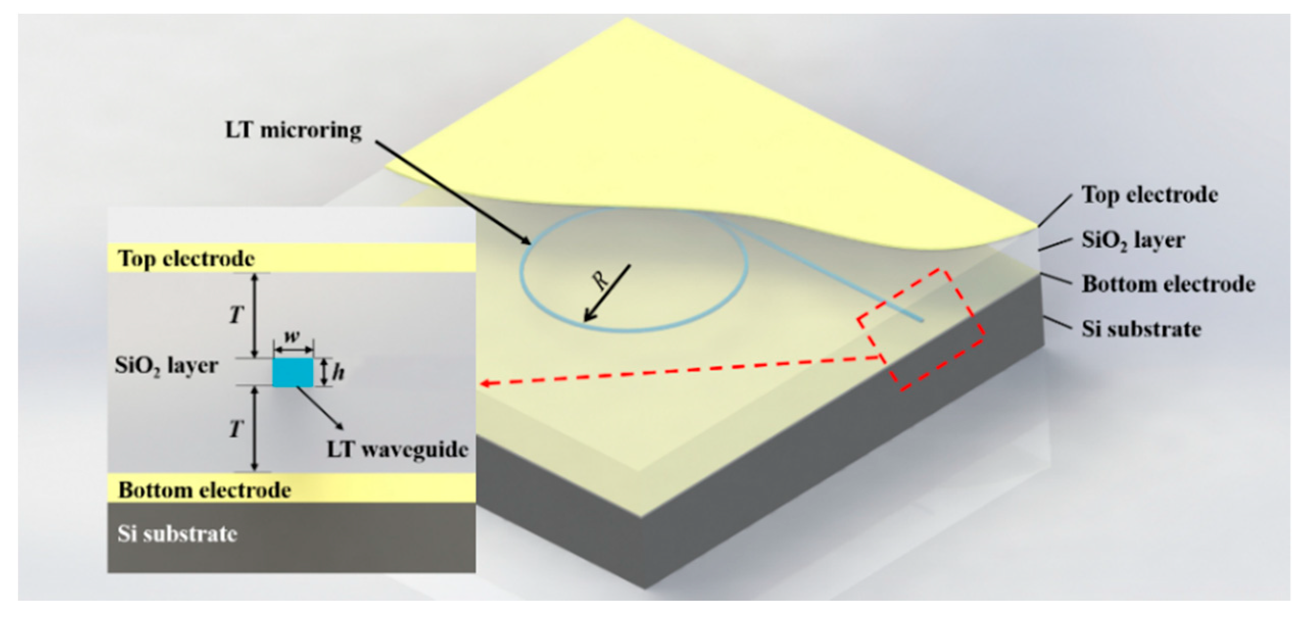
Figure 1. Schematic showing the waveguide-coupled microring resonator on LTOI. Inset: cross-section of the LT waveguide structure.
Crystals 11 00480 g001
Figure 2. Graphs showing the effective index of the TE and TM light modes as a function of (a) the film thickness with a waveguide width of 0.7 µm and (b) the waveguide width with a film thickness of 0.5 µm in the LT waveguide. Both are calculated at λ = 1.55 µm.
Crystals 11 00480 g002
Figure 3. Graph showing the transmission loss of the LT waveguides with different thicknesses of the SiO2 layer for TM light mode.
Crystals 11 00480 g003
Figure 4. Graphs for (a) the Q-factor of the microring resonators at different ring radii and gap sizes and (b) the FSR at different microring radii for a TM light mode at around λ = 1.55 µm.
Crystals 11 00480 g004
Figure 5. Transmission spectrum of the microring with radius 20 μm for TM light mode.
Crystals 11 00480 g005
Figure 6. Diagram showing the optical field inside the waveguide.
Crystals 11 00480 g006
Figure 7. Graph showing the wavelength shift of the transmission spectrum at different electric field intensities. In this case, a TM mode and a microring with a 20 µm radius are used.
Crystals 11 00480 g007
Figure 8. Graph showing the transmission spectra for the drop port of the LT microring at different electric field intensities.
Crystals 11 00480 g008
Figure 9. Diagram showing the electrostatic field strength when a voltage is applied to the electrodes.
Crystals 11 00480 g009
Table 1. The refractive indexes for LiTaO3, SiO2, and Si at λ = 1.55 µm.
MaterialLiTaO3SiO2Si
Refractive indexno = 2.1189
ne = 2.1228
1.463.47
Table 2. Comparison between the different types of LiNbO3 and LiTaO3 tunable microrings.
MaterialModeEO Tuning (pm/V)Ref
x-cut LNOITE2.4[15]
x-cut LNOITE7[35]
y-cut LNOITE0.32[36]
z-cut LNOITM3[39]
z-cut LNOITM1.05[20]
z-cut LNOITM2.15[40]
z-cut LTOITM2.6This work
Publisher’s Note: MDPI stays neutral with regard to jurisdictional claims in published maps and institutional affiliations.

