Review

Recent Developments in Carbon Nanotubes-Reinforced Ceramic Matrix Composites: A Review on Dispersion and Densification Techniques

1
Department of Physics, Faculty of Science, Universiti Putra Malaysia, Serdang 43400, Malaysia
2
TriPrem i-Kohza, Malaysia-Japan International Institute Technology, Universiti Teknologi Malaysia, Kuala Lumpur 54100, Malaysia
3
Department of Physical Science and Engineering, Graduate School of Engineering, Nagoya Institute of Technology, Gokiso-cho, Showa-ku, Nagoya 466-8555, Japan
*
Author to whom correspondence should be addressed.
Crystals 2021, 11(5), 457; https://doi.org/10.3390/cryst11050457
Submission received: 17 March 2021 / Revised: 5 April 2021 / Accepted: 15 April 2021 / Published: 21 April 2021
(This article belongs to the Special Issue Functional Glass-Ceramics)

Abstract

:
Ceramic matrix composites (CMCs) are well-established composites applied on commercial, laboratory, and even industrial scales, including pottery for decoration, glass–ceramics-based light-emitting diodes (LEDs), commercial cooking utensils, high-temperature laboratory instruments, industrial catalytic reactors, and engine turbine blades. Despite the extensive applications of CMCs, researchers had to deal with their brittleness, low electrical conductivity, and low thermal properties. The use of carbon nanotubes (CNTs) as reinforcement is an effective and efficient method to tailor the ceramic structure at the nanoscale, which provides considerable practicability in the fabrication of highly functional CMC materials. This article provides a comprehensive review of CNTs-reinforced CMC materials (CNTs-CMCs). We critically examined the notable challenges during the synthesis of CNTs-CMCs. Five CNT dispersion processes were elucidated with a comparative study of the established research for the homogeneity distribution in the CMCs and the enhanced properties. We also discussed the effect of densification techniques on the properties of CNTs-CMCs. Additionally, we synopsized the outstanding microstructural and functional properties of CNTs in the CNTs-CMCs, namely stimulated ceramic crystallization, high thermal conductivity, bandgap reduction, and improved mechanical toughness. We also addressed the fundamental insights for the future technological maturation and advancement of CNTs-CMCs.

Graphical Abstract

1. Introduction

Ceramic materials are well known for their corrosion resistance, chemical inertness, high strength, and high thermal stability, which makes these materials suited for applications involving harsh environmental conditions or high-temperature exposure. Related industries such as metallurgical and chemical sectors demand low-density ceramic materials that possess high refractoriness and corrosion resistance for implementation in the revolutionary application. To meet the demand, numerous ceramic synthesis routes have been established: sol–gel [1,2], supercritical fluid [3,4], hydrothermal [5,6,7], solid-state [8,9], and polymer-derived ceramics [10,11]. Even with the superior properties and well-established synthesis techniques, monolithic ceramic materials have yet to become the first option applied in bulk structural components, because of the low thermal transport properties, low electrical properties, and brittleness (low fracture toughness KIC). Throughout the years, the scientific and engineering communities have countered the elevated thermal, electrical, and mechanical deficiencies of monolithic ceramics by developing ceramic matrix composites (CMCs). Many reinforcements (i.e., nanorods, nanotubes, and particulates) have been implemented in bulk glass–ceramics and polycrystalline ceramic matrices. As compared to their counterparts, these reinforced ceramic materials showed significant improvements in their thermal transport and electrical conduction properties, and crack propagation was limited (increasing the strength). The enhanced characteristics allowed CMCs to be engaging materials for structural applications.
In 1991, Iijima from the NEC Corporation (Japan) discovered carbon nanotubes (CNTs) [12], which contribute to many aspects of nanoscience and nanotechnology applications today. CNTs and carbon nanofibers (CNFs, a type of carbon allotrope) share cylindrical shapes, which can be formed by wrapping graphene sheet/s along the axial direction. The difference between CNTs and CNFs is the core structure: a hollow structure for CNTs but a concentric structure for CNFs. Carbon atoms in most types of CNTs are arranged in a honeycomb lattice featuring sp2 hybridization. CNTs can be commonly found in single-walled carbon nanotubes (SWCNTs, single wrapping graphene sheet) and multi-walled carbon nanotubes (MWCNTs, additional graphene tubes along the core of SWCNTs). The average diameter of pristine SWCNTs is lower than 10 nm and the diameter of pristine MWCNTs ranges from 10 to 100 nm, with both CNT types possessing fullerene capping at the two ends [13]. When it comes to practicability, the main difference between SWCNTs and MWCNTs is the material cost, e.g., 31–1160 USD/gram (SWCNTs) and 11.4–156 USD/gram (MWCNTs), according to Sigma Aldrich. The high cost of SWCNTs is due to the critical environment and parameter control during the fabrication. The preference between SWCNTs and MWCNTs as the ideal filler in the matrix remains debated. AfzaliTabar et al. reported that the MWCNTs-SiO2 nanohybrid is a better candidate for Pickering emulsion stability over SWCNTs-SiO2 [14]. Nadeem et al. compared the Nusselt number (ratio of thermal convection to conduction) of SWCNTs and MWCNTs in water, ethylene glycol, and kerosene, showing that MWCNTs possess lower Nusselt numbers and higher conductive thermal transfer values [15]. Cao et al. reported hexadecyl acrylate with functionalized single carbon nanotubes (HDA-g-SWCNTs) solid–solid phase-change materials as the heat spreader for electronic cooling applications [16]. The reported HDA-g-SWCNTs exhibited a higher electrical conductivity, phase-transition enthalpy, and crystallization enthalpy, but a lower thermal conductivity, than those of HDA-g-MWCNTs.
The nature of CNTs can be crystalline, amorphous, and a mixed state, which depends on the fabrication technique. Several techniques have been reported for CNTs synthesis: arc discharge [12], laser ablation [17], chemical vapor deposition [18], and gas-phase catalytic growth [19]. Arc discharge and laser ablation-synthesized CNTs possess a high-quality graphitic lattice, but high energies are required and the CNTs yield is low. By contrast, chemical vapor deposition (CVD) and gas-phase catalytic growth require relatively low energies but provide CNTs with moderate-quality graphitization. The chirality, geometrical parameters, and synthesis routes are key factors that affect the optical [20], electrical [21], and mechanical [22] properties of CNTs. CNTs also possess remarkable thermal properties such as high thermal stabilities up to 2000 °C [23], and high thermal conductivities (κth = 600 W/mK) [24] and thermal diffusivities (D = 39 mm2/s) [25].
However, CNTs with such excellent properties are rarely introduced as domains in bulk components; instead, they mostly act as fillers in glass [26], ceramic [27], metal [28], polymer [29] and alloy [30] composites. This is due to the high synthesis cost, the intrinsic toxicity, and the underperformed properties of neat CNTs. The high synthesis cost is a well-known factor causing the CNTs to barely act as a domain structure. From the synthesis routes mentioned, CNTs are produced together with side-products such as amorphous carbon, graphite/graphene layers, and carbon dots. Several steps of purification require extra effort and cost during the chemical and thermal treatment, and they have been made to distinguish CNTs from the carbon impurities and to optimize the CNTs yield. Moreover, the combination of the large surface area and toxicity of CNTs has the potential to be harmful to lungs, modify protein structures, and activate immunological responses [31]; therefore, the composition of CNTs in the domain matrix is controlled in small amounts. In addition, CNTs as fillers in composites perform better than standalone CNTs. Xiao et al. studied the discharge performance of neat CNTs, VO2, and VO2/CNTs as anodes for lithium-ion batteries [32]. They showed that neat CNTs and bare VO2 both exhibited low discharge capacities (363.8–177.9 mAh/g), but the VO2/CNTs composite showed larger capacities ranging from 493 to 301 mAh/g. They reported that the discharge capacity of neat CNTs decreased with the current density from 0 to 400 mA/g, and it remained on a plateau of 260 mAh/g, with the current density ranging from 400 to 2000 mA/g (see Figure 1). The discharge capacity of the VO2/CNTs-10 mg composite followed a downward trend similar to VO2 with increasing current density, but with an average of a 41.2% higher discharge capacity. They deduced that the enhancement of the discharge capacity was attributed to the CNTs-induced porosity and larger specific surface area from 13.8 m2/g (VO2) to 24.8 m2/g (VO2/CNTs). Peng et al. [33] also found that MWCNTs without the CdS domain showed a near-zero photocatalytic activity for H2 production under visible light irradiation (λ ≥ 420 nm). This was attributed to its semiconductive behavior, which cannot produce H2 under visible light radiation. With a functionalized MWCNTs content of 10 wt.% (which is optimized), the average H2 production rate increased from 97.9 (pure CdS) to 174.2 μmol/h (Cds/MWCNTs-10 wt.%). MWCNTs acted as ideal electron acceptors and transfer channels; however, the H2 production efficiency decreased for CdS containing >10 wt.% MWCNTs. This was due to the relative amount of CdS decreasing with the presence of MWCNTs and the reduction of photogenerated carriers in the photoreaction system.
After the discovery of CNTs, CNTs-reinforced CMCs (CNTs-CMCs) have gained the attention of researchers for their excellent microwave absorbance [34], water decontamination [35], ceramic strengthening [36], and oxidation and ablation resistances [37]. To ensure the future of CNTs-CMCs, many scientific studies have been conducted, and many have failed. Researchers determined that the remarkable properties of the CNTs-CMCs were the result of how the key challenges along with the CNTs-CMCs processing were eliminated or solved. Generally, the challenges include achieving a homogenous CNTs distribution within the ceramic (see Figure 2), forming a suitable interfacial adhesion, lowering the thermal degradation, and optimizing the sinterability and densification of the CNTs-CMCs without causing structural damage to the CNTs and ceramic matrix. A previous study revealed an inconsistent improvement in CNTs-CMCs from many aspects, e.g., a CNTs reinforcement of 1 wt.% improved the KIC of CNTs-zirconia by about 9% [38], but the same CNTs content (1 wt.%) strengthened the KIC of CNTs-Al2O3 to 36.74% [39]. For microwave application, an identical amount of CNTs addition also showed uncertain performance—the microwave absorption of iron acetylacetonate-modified polymethylsilsesquioxane polymer-derived ceramic composites, PMS(Fe), containing 3% of MWCNTs improved by 29% [34], while 3% of CNTs-Sc2Si2O7 reached a 175% absorption [40], as compared to their counterpart. The role of the CNTs reinforcement mechanism has yet to be elucidated and established for high amounts of CNTs contained in the CNTs-CMCs. To explain the enhancement of properties of CNTs-CMCs, the mechanism and possible deformation at low-dimensional scales and subsequent postulated formulations need to be investigated.
Therefore, the present review contains four sections, comprehending the overall knowledge of the CNTs-CMCs processing-densification-property correlations. Section 2 introduces the critical challenges during the CNTs-CMCs fabrication and the end product characteristics. Section 3 discusses various processing methods for the dispersion of CNTs into the ceramic matrix to distinguish the processing’s complexity and efficacy. Section 4 contributes to a thorough review of established CNTs-CMCs densification and sintering techniques and the effects on the characteristics of the end product. Finally, the functional properties of CNTs-CMCs are highlighted in Section 5. The simple advantage–disadvantage comparison on the CNTs-CMCs processing and densification and sintering routes are displayed, concluded, and summarized.

2. Critical Challenges

2.1. Homogenous Dispersion

This is the most difficult challenge when preparing CNTs-CMCs. The nanotubes are most likely bundled or agglomerated, and this causes a non-uniform distribution within the composites. A non-uniform CNTs distribution will lead to the degradation of the fracture toughness upon indentation analysis. A large amount of CNT bundles cause porosity and reduce the contribution of CNTs to the reinforcement mechanism [41]. It also impacts the anisotropic properties of ceramics [42], and it results in a significant difference in radial cracks perpendicular and parallel to the random CNTs orientation where the degree of CNTs bridging is low [43]. Various dispersion methods have been developed to disperse CNTs homogenously and eventually enhance the CNTs-CMCs properties. Sol–gel [44], hydrothermal/solvothermal [45], and colloidal processing [46] are examples of applications of surface functionalization on CNTs to achieve a homogenous dispersion, while the in situ growth of CNTs by chemical vapor deposition (CVD) can achieve a homogenous CNTs distribution via growing CNTs at the designed growth site (the metal catalyst) within the ceramic precursor [47].

2.2. Suitable Interfacial Adhesion between CNTs and Ceramic

Functional properties such as thermal and mechanical properties are highly dependent on the interfacial adhesion and the surface morphology [29]. For instance, strong phonon scattering takes place when there is a weak CNTs–ceramic interaction, resulting in a large thermal resistance. Moreover, a weak CNTs–ceramic interfacial adhesion enhances the crack propagation and negatively influences other toughening mechanisms such as crack bridging [48,49,50]. CNTs with a large lattice oxygen content will deteriorate mechanical properties such as surface hardness and wear depth, where the surfaces between CNTs and the domain ceramic are incompatible and the adhesion is extremely weak [43,51]. A high chemical inertness of pristine CNTs is the major cause of the near-zero chemical affinity of CNTs toward the ceramics. CNTs are neither polar nor lipophilic and ordinary aromatic, where the π-electron population is not balanced by the aromatic hydrogens.
Surface functionalization helps to enhance the quality of CNTs adhesion and increase the chemical affinity toward the matrix. During the functionalization, the CNT walls are partially damaged and attached with functional groups such as carboxyl (-COOH) [41], hydroxyl (-OH) [52], amine (-NH2) [53] groups, and C-F [54] bonds. The attached functional groups provide hydrophilic properties to CNTs for a stable water (or solvent) dispersion [55] and also to improve the interfacial adhesion with the ceramic matrix, which expresses the enhancement in terms of KIC [56], Young’s modulus [57], corrosion resistance [58], and thermal conductivity [59]. Hence, the interface engineering is essential to understand and overcome the development of extremely hard, strong, and low-density CNTs-CMCs.

2.3. Thermal Degradation

During the densification and sintering of CNTs-CMCs, the temperature, pressure, environment, and duration are important for the crystallization of the ceramic and the maintaining of the primitive nature of CNTs. Studies in the literature have shown that high pressures, high sintering temperatures, and prolonged sintering durations can negatively affect the CNTs’ nature and cause allotropic transformation and thermophysical damage [60]. Structural damage on the CNT walls was observed in CNTs-CMCs when they underwent spark plasma sintering (high temperature and pressure) and pressureless sintering (long sintering duration) [61].

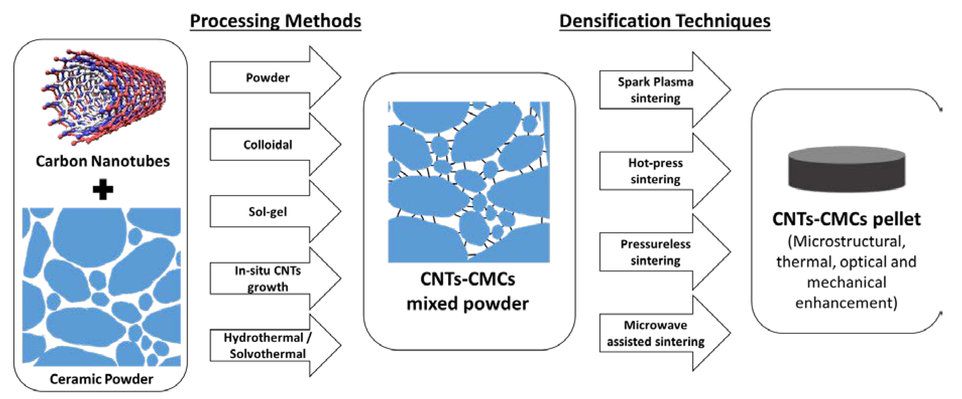
3. Processing Methods

3.1. Powder

Powder processing is an established CNTs-CMCs fabrication technique for the production of near-neat shape products. This technique is also useful for its batch production and the integrated weight fractions of the raw material. Powder processing requires two or three steps. Figure 3 compares the two-step and three-step powder processing. The two-step powder processing involves the mixing of CNTs and ceramic powder, followed by in situ densification and sintering such as spark plasma sintering (SPS) and hot-press sintering (HPS), while the three-step processing involves mixing, densification, and sintering, such as pressureless sintering (PLS) and microwave-assisted sintering (MAS). Several techniques could be applied at the mixing process: manual mixing [62], planetary milling [63], ball milling [38,64,65], and high-energy ball milling [66]. The mixing is commonly performed using dry CNTs and ceramic powder, but it often requires a solvent like alcohol or acetone as a medium, known as wet-mixing, where the solvent is later evaporated. Removing the aggregation and achieving a homogenous CNTs distribution are the ultimate goals of this step. This processing technique is suitable for preparing CMCs with large amounts of CNTs, and it is applicable to the thermal enhancement [62,67] and mechanical enhancement [68,69] of CNTs-CMCs.
Ye et al., improved the KIC and flexural strength of barium aluminosilicate (BAS) glass–ceramic composites by adding MWCNTs through wet powder processing [70]. They sonicated and ball-milled the MWCNTs-BAS in ethanol into the MWCNTs-BAS slurry. Next, the slurry was dried and hot-pressed (1600 °C, 1 h, 20 MPa, N2 atmosphere) into ceramic pellets for mechanical analysis. They noticed that the addition of 10 vol.% MWCNTs increased the flexural strength from 84 to 245 MPa (about 300%) and the KIC increased from 1.22 to 2.97 MPa·m1/2. Good MWCNTs-BAS interfacial bonding, the high elastic modulus of CNTs, and the CNTs bridging contributed to the enhanced mechanical properties. By contrast, the relative density of 15 vol.% CNTs-added composites decreased by 3% and the flexural strength only achieved 169 MPa, which was due to the effect of the agglomerated CNTs (see Figure 4). Moreover, Chan et al. reduced the lattice strain of zinc silicate CMCs upon the addition of CNTs [71]. They prepared CNTs through CVD on a cobalt oxide metal catalyst and through the manual mixing of the CNTs with zinc silicate glass powder. The CNTs-zinc silicate glass powder was further sintered in Ar atmosphere, and the zinc-silicate glassy phase changed to the polycrystalline willemite phase (Zn2SiO4). Through the phase analysis, CNTs showed an insignificant phase alteration to the domain Zn2SiO4 crystal structure but only introduced the graphite (C) and cobalt oxide (CoO) phases. They also noticed that the lattice strain of 3 wt.% CNTs-Zn2SiO4 reduced by 22.85% and the crystallite size of 1 wt.% CNTs-Zn2SiO4 CMC increased by 5.65%, as compared to the CNTs-free Zn2SiO4 composite.

3.2. Colloidal

Colloidal processing involves several physical/chemical practices to disperse CNTs with water/solvent, eventually turning into CNT nanofluid. The options of the CNT dispersant are limited because it needs to meet the dispersion compatibility and the sinterability upon the densification and sintering with the ceramic domain. Critical dispersion steps, such as sonication, magnetic stirring, and chemical oxidation, are taken for the CNTs nanofluid production. The CNT nanofluid is added to the ceramic powder and densified for the final CNTs-CMCs product. Figure 5 displays the schematic of colloidal processing.
N,N-Dimethylformamide (DMF) was first applied to disperse the low concentration of MWCNTs and SWCNTs with near-zero disruption to the structure [72]. Acetone was applied onto oxidized MWCNTs to achieve dispersion where acetone formed the solubilizing phase with the hydroxylated modified MWCNTs surface [73]. Carboxylated MWCNTs (MWCNTs-COOH) can be dispersed in diethyl ether with the addition of 4-fluoroaniline in a N2 atmosphere [54]. Molecular dynamic (MD) simulations [74] and experimental studies [75] showed that pyrogallol and 1-naphthol had high binding coefficients to MWCNTs and increased threefold as the experimented MWCNTs diameter reduced from 100 to 10 nm (effect of agglomeration increased as diameter decreased). Solvents with a high density of aromatic structure are mostly dispersed SWCNTs at ease with the aid of planar polycyclic aromatic hydrocarbons as compared to linear structure solvents [76]. Previous studies in the literature on the dispersion medium, surfactant, and other additives are displayed in Table 1.

3.3. Sol–Gel

Sol–gel processing techniques are effective for fabricating CNTs-CMCs with a homogenous CNT dispersion and a uniform size distribution of ceramic crystals. CNTs are sonicated in an aqueous solution (or solvent) with minimum surfactant addition (known as the CNT sol). In order to prepare CNTs-CMCs gel, a series of solutions (ceramic precursor, gelling agent, and pH control agent) are added into the CNT sol, and ageing or the gelation process is carried out. The CNTs-ceramic gel is then dried, calcined at high temperature with (without) inert gas, and left with the CNTs-ceramic powder (see Figure 6).
Liu et al. compounded strontium titanate (SrTiO3)-coated MWCNTs in epoxy resin (EP) toward high-dielectric-constant percolative polymer composites [89]. First, they prepared an Sr2+ aqueous solution and TiO32− ethanol solution, with acetyl acetone as the chelating agent. Then, they added the acidified MWCNTs with sodium dodecyl benzene sulfonate (SDBS) as the CNT surfactant into the as-prepared SrTiO3 solution. The SrTiO3-MWCNTs composites were stirred for 3 h at 40 °C (gelation), dried overnight, and calcined at 800 °C before compounding with EP. The obtained dielectric constant of EP-compounded 11 vol.% SrTiO3-MWCNTs reached 283 and the dielectric loss was 0.07 at 1 kHz, where the dielectric constant of EP-compounded 11 vol.% neat MWCNTs reached 1600 and the dielectric loss was 25. They deduced that the SrTiO3 coating acted as barriers between CNTs, and it resulted in a low dielectric loss, which improved the dielectric properties. The tribological properties of the metal/alloy surface can also be enhanced when it is coated with a thin layer of CNTs-CMCs. Xu et al. coated a 0.25 wt.% CNTs-Al2O3-ZrO2-ZrSiO4 ceramic sol–gel mixture on A4 steel to enhance the wear rate at an escalated temperature [90]. Acidified CNTs were first dispersed in SDBS solution, transferred to the aluminium dihydrogen phosphate Al(PO2(OH)2)3 solution (containing the ceramic powder), and cured for 5 h before brushing on the steel surface. It showed that the CNT fillers (0.25 wt.%) effectively lowered the CNTs-CMCs-coated steel’s wear rate with temperature: 57% (100 °C), 67% (300 °C), and 87.5% (500 °C), as compared to the bare ceramic coating.
Moreover, sol–gel processing is a favourable technique during the carbon-ceramic electrode (CCE) fabrication for its high CNT dispersion homogeneity. CNTs incorporating CCE were developed to detect nicotinamide adenine dinucleotide (NADH) [91], sulfonamide drugs [92], and purine derivative [93], as well as for wastewater treatment [94]. Ferrag et al. developed CNTs-Au-CCEs to detect the purine derivatives, uric acid (UA), xanthine (XA), and caffeine (CA) [93]. They mixed 3-mercaptopropyl-methyl-dimethoxy silane (MPDS, Si-based sol–gel network), hydrochloric acid, and the carbon mixture (50 mg CNTs: 150 mg graphite powder) in methanol, and they dried out the liquid mixture. The dried ceramic product was impregnated with Au solution and then molded in a narrow glass tube. Comparing the CNTs-Au-CCEs and the bare CCE, the diffusion coefficients for UA, XA, and CA improved: 3.5 times (UA), 1.56 times (XA), and 2.26 times (CA). The limit of detection (LOD) values of the CNTs-Au-CCE for UA, XA, and CA were 50, 63, and 354 nM, where the limits of quantification (LOQ) were 167, 209, and 1179 nM, respectively. Table 2 shows the dispersion medium, dispersant (or surfactant), gelling agent, and the gelation process when preparing the CNTs-CMCs gel.

3.4. In Situ CNTs Growth

In situ synthesis is the attempt for CNTs-CMCs to grow CNTs on the ceramic matrix directly, and it is widely performed through chemical vapour deposition (CVD). Generally, the ceramic powder is prepared with metal salt (such as metal nitrate or acetate salt) in an aqueous solution or solvent to ensure complete metal ion impregnation within the ceramic domain. Next, the ceramic-metal solution is reduced at high temperature with the presence of H2 as the metal salt reduces to metal oxides and further reduces to metal nanoparticles. The nanoparticles act as the active growth site for CNTs, so the carbon solubility is critical. The commonly used transition metal catalysts are Fe, Ni, and Co for their moderate-to-high carbon solubility at elevated temperatures. Carbon atoms for the CNTs growth come from the carbon precursor (CH4, C2H2, ethanol, etc.) and are carried by the flowing gas (such as Ar, N2, He) within the CVD system (see Figure 7). The deposition of carbon atoms (carbonaceous molecule from the carbon precursor) involves several mechanisms: carbon adsorption on the catalyst surface, the dissolution of carbon molecules (segregation of hydrogen bonding), carbon diffusion into the catalyst, the formation of the carbon network and the growth of CNTs. Table 3 displays the optimum parameters for in situ CNTs growth on ceramic.
Chen and co-workers prepared Si3N4-CNTs composites through in-situ CNTs growth via CVD [102]. The ceramic possessed an extraordinary electromagnetic shielding effect over the X-band frequencies (f = 8.2–12.4 GHz), where the total shielding effectiveness increased from 6.0 (neat Si3N4) to 30.4 dB (2.7 wt.% CNT). They impregnated Si3N4 with 10 wt.% cobalt acetate tetrahydrate (CoAc·4H2O) and fed the CVD system with Ar-carried acetone vapor (CH3)2CO. Vapor deposition took place at 550 °C and lasted for 1 h. As per 10 wt.% CoAc catalyst, they managed to produce 2.7 wt.% feather-like CNTs (outer diameter, d = 10 nm) with a 0.75 ID/IG ratio (see Figure 8). The growth of CNTs interconnected the Si3N4 grains and improved the shielding properties. The resulting Si3N4-2.7 wt.% CNTs composites improved the absorbance shielding effectiveness (SEA) from >5 (neat) to 22 dB, and the reflectance shielding effectiveness (SER) increased from 2 to 8 dB over the X-band.
To improve the Cu2+ removal of the porous Al2O3 ceramic membrane, Tofighy and Mohammadi grew CNTs on the membrane by using an organometallic catalyst (Feroccene, Fe(C5H5)2) and cyclohexanol HOCH(CH2)5 as carbon feedstock [103]. Under transmission electron microscope (TEM) observation, the outer diameter of CNTs ranged from 30 to 40 nm, and it showed a rigid and flawless structure. The Al2O3-CNTs membrane was tested for the permeation flux and rejection of Cu2+ ions in a weak acidic environment (pH = 6) for 10 min. The permeation flux reduced from 523.65 to 45.98 kg/m2h, while the Cu2+ rejection increased from 2.76% to 20.27%. They discussed that the reduced permeation flux and the increased Cu2+ rejection were the outcomes of the CNTs filling the membrane pore void, as it increased the membrane resistance. Ding et al. grew CNTs on FeCl3-implanted polysiloxane at 800–1500 °C for high electromagnetic waves (EMW)-absorbing applications [104]. Instead of using gas-carried precursor vapor, they dissolved the FeCl3-polysiloxane in ethanol and carried out the reaction for 2 h in Ar atmosphere. During the CVD at 900 °C, the ID/IG ratio was 1.01, and the measured CNTs crystallite size (La, Equation (1), where λ is the laser wavelength of the Raman spectroscope) [105,106] was 16.65 nm. However, more defects formed on the CNTs, causing the ID/IG ratio to increase to 2.46 and La to decrease to 6.84 nm when the reaction temperature was 1500 °C. Transmission electron microscope (TEM) analysis revealed that the CNTs experienced a structure breakdown, and the SiC grew in various morphologies such as microspheres, needle-like, and nanowires at high temperature. In this case, CNTs provide a casting mold for the growth of SiC micro- and nanostructures, and the formed SiC showed a low reflection loss of −58.37 dB at 10.11 GHz.
L a ( nm ) = ( 2.4 × 10 10 ) λ 4 ( I D I G ) 1
In situ synthesis is a simple method to synthesis large volumes of CNTs-embedded CNTs-CMCs with a minimum amount of bundled CNTs and agglomeration. Besides, this method provides CNTs-CMCs with a highly ordered unidirectional orientation, which is enables the comparison of the toughening mechanism between microfibers-reinforced ceramic and CNTs-CMCs. However, the quality of CNTs within the ceramic is not consistent, because the CNTs growth mechanism on the active metal nanoparticles is greatly dependent on various parameters—temperature, deposition duration, amount and purity of metal catalyst, gas flow, and carbon precursor.

3.5. Hydrothermal/Solvothermal Processes

Hydrothermal and solvothermal processes are well-established CNTs-CMCs techniques for homogenous CNT dispersions with a low number of impurities. Generally, acid-functionalized CNTs are dispersed in water (hydrothermal) or solvent (solvothermal), together with the ceramic salt with (without) the surfactant. The surfactant reduces the interfacial resistance among the ceramic salt, CNTs, and the dispersion medium. The aqueous mixture of CNTs and salt is magnetically stirred or sonicated for CNTs disentanglement and to improve the CNTs-CMCs homogeneity. Next, the mixture is stored in an autoclave and heated from 100 to 250 °C for several hours to several days, highly dependent on the crystallization of the domain ceramic (Figure 9).
Zhao et al. prepared low-bandgap MWCNTs-Bi2S3 composites for methylene blue (MB) wastewater treatment [109]. Before the hydrothermal processing, they applied acid treatment (stirred with HNO3, 80 °C, 12 h) to functionalize CNTs. The CNT wall with the carboxyl group -COOH resulted in a higher miscibility with water. The composite was prepared by stirring the bismuth nitrate (Bi(NO3)3·5H2O), urea, and MWCNTs in deionized water and heating in an autoclave at 120 °C for 12 h. The hydrothermally treated composites were centrifuged, rinsed with alcohol-water, and dried overnight into MWCNTs-Bi2S3 ceramic powder. Using 5 wt.% MWCNTs, the bandgap value of Bi2S3 powder reduced from 1.245 to 0.875 eV, and the Brunauer–Emmett–Teller (BET) surface area increased from 35.2 to 36.1 m2/g. With the low-bandgap value and larger surface area, the photocatalytic activity (the MB degradation) under visible-light irradiation reached 90.75% in the first cycle and was maintained at about 75% after the fourth cycle. Besides, MWCNTs as the filler effectively improved the sensing device, e.g., ammonia sensor. Singh et al. shortened the response and recovery time of a MoS2-based ammonia sensor by adding a relatively low amount of CNTs during the hydrothermal process [45]. They prepared the ceramic ammonia sensor by sonicating 1 g of ammonium tetra-thiomolybdate (NH4)2MoS4, 10 mL of hydrazine monohydrate N2H4·H2O, and 3 mg of MWCNTs in deionized water. Next, the mixture was transferred to an autoclave, heated at 200 °C for 12 h, and dried in an oven for 2 h. The obtained black powder (after drying) showed a larger surface area of 20.23 m2/g, where the surface area of neat MoS2 was 4.22 m2/g. For the ammonia response determination, neat MoS2 required 400 s to detect the NH3 content when the concentration was low as 150 ppm, while the MoS2-MWCNTs hybrid was more capable of rapid detection (response time = 65 s), which was six times faster than the neat one and was due to the larger surface area. Li et al. discussed the dielectric performance of the poly(1-butene) polymer filled with modified polydopamine and Ba(Zr0.2Ti0.8)O3-MWCNTs as a diaphragm in capacitors [110]. The Ba(Zr0.2Ti0.8)O3-MWCNTs were prepared through sol–gel processing on barium acetate Ba(COOCH3)2 (dissolved in acetic acid and DI) and tetrabutyl titanate Ti(CH3(CH2)3OH)4 (dissolved with isopropanol zirconium in glycol methyl ether), and then by carrying out the hydrothermal processing with MWCNTs in NaOH aqueous solution. The temperature and duration of the hydrothermal process was set at 180 °C for 24 h, and the obtained Ba(Zr0.2Ti0.8)O3-MWCNTs was then transferred on the poly(1-butene) polymer film. The analysis showed that the dielectric constant of the film improved from 4.4 to 28.40 with the addition of 0.5 vol.% CNTs at 1 kHz, and the dielectric loss was 0.0077, which makes this composite a potential candidate as an intermediate phase and insulating layer.
In addition to hydrothermal treatment, solvothermal processing also offers promising results. Vadivel et al., improved the BiPO4 nanorod’s capacitance and its photocatalytic activity on methyl orange degradation by introducing MWCNTs via the solvothermal process [111]. They dispersed bismuth nitrate (Bi(NO3)3, Bi3+ precursor), monoammonium phosphate (NH4H2PO4, PO43− precursor), and untreated MWCNTs (with PVP as a surfactant) in ethylene glycol (EG). The weight ratio of the mixture Bi3+:PO43−:MWCNTs was 1.5:0.85:0.05. The mixture was then sealed in an autoclave and heated at 160 °C for 12 h. The measured specific capacitances (current density = 1 A/g) of neat MWCNTs and pristine BiPO4 were 45 and 292 F/g, respectively, while the BiPO4-MWCNTs reached 368 F/g at the identical current density. The stable photocatalytic activity of the composite under indigo irradiation (464 nm) also reached 95% of methyl orange degradation after a 150 min test time. The enhanced capacitance and photocatalytic activities were due to the large surface area of BiPO4-MWCNTs (38.25 m2/g), which was 1.53 times larger than that of pristine BiPO4. Solvothermal processing also enables the oxide coating on the wall of CNTs. Zhang and Hao coated layers of rare earth oxide on the CNTs wall toward the effective thermal decomposition of ammonium perchlorate (AP, a type of oxidizer in solid propellant) [112]. They enlarged the surface area of CNTs with HNO3, and they modified the CNTs polarity with cetyl trimethylammonium bromide (CTAB) and poly(sodium 4-styrenesulfonate) (PSS). The rare earth nitrate salt (Y3+, Nd3+, and Sm3+), modified CNT, sodium acetate (NaAc), and polyethylene glycol (PEG) were dissolved and stirred in EG, and they were heated in the reaction system in a 200 °C oil bath for 2.5 h. The AP’s thermal decomposition peak temperature reduced from 452 to 326.5 °C with the addition of 2 wt.% Y2O3-CNTs, and the DTA heat released increased from 0.281 to 2.308 kJ/g. It showed that the thermal decomposition of AP decreased because of the large surface area and the partially filled 4d orbital in the rare earth material, which is favorable for electron transfer. Table 4 and Table 5 show the optimized parameters of the surfactant-CNTs ratio and the hydrothermal (solvothermal) processing.
Hydrothermal and solvothermal processes bring benefits in preparing high-quality CNTs-CMCs with low synthesis temperatures. However, the processing duration (involving heating, cooling, and drying) is longer than those of other processing techniques. In addition, the starting materials such as the ceramic precursor and the surfactants (or dispersants) for CNT dispersion are expensive, and the final yield is low because the molecular ratio of ceramics in the precursor is mostly low. For example, the stable hydrogen evolution reaction (HER) candidate, molybdenum sulfide/reduced graphene oxide-carbon nanotube composites (MoS2/RGO/CNTs), was where the MoS2 compound was produced from ammonium thiomolybdate salt (NH4)2MoS4 [113]. The weight ratio of one mole of MoS2 is about 61% per one mole of the (NH4)2MoS4. A small amount of end product explains that the hydrothermal and solvothermal processes are not favorable in CNTs-CMCs mass production, but they are fit for research purposes and the high-purity requirement.

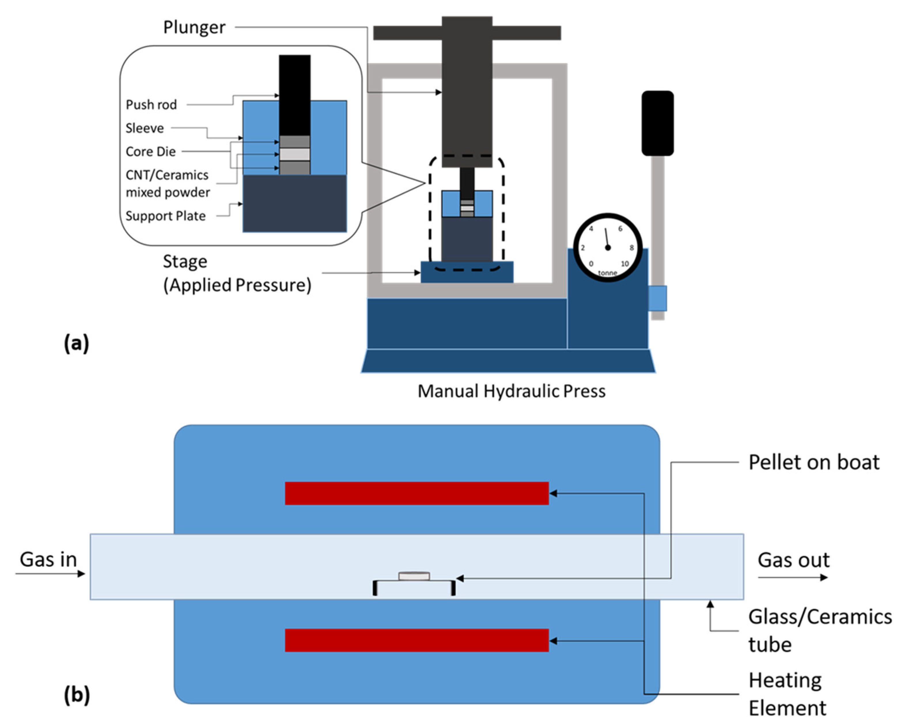
4. Densification and Sintering Techniques

Densification and sintering are the critical treatments for CNTs-CMCs interaction by shaping the powder and supplying energy (thermal/electrical) to the matrix itself. This process inputs high energy in promoting the crystallization of the domain ceramic crystal and bond-breaking of C=C bonds of CNTs. Generally, a CNTs-CMCs pellet with a desired dimension is produced through an applied pressure before or during the thermal treatment. Hereafter, four common techniques are reviewed: spark plasma sintering (SPS), hot-press sintering (HPS), pressureless sintering (PLS), and microwave-assisted sintering (MAS). The rapid heating in SPS and MAS offers a time-efficient route by heating the CNTs-CMCs at a high temperature for a short duration (<15 min); however, the setup and fabrication are expensive. On the other hand, HPS and PLS produced a cheaper composite with flexible size and shape, yet at the risk of a lower density and long sintering duration (>1 h).

4.1. Spark Plasma Sintering (SPS)

The success of spark plasma sintering (SPS) has been highlighted by noteworthy achievements of, for example, an outstanding increase in tensile strength of ceramic material composed of CNTs. During the SPS process, the CNTs-ceramic mixed powder is sintered under the simultaneous effect of a pulsed direct current (PDC) and an applied pressure in a vacuum chamber. The powder is placed in a die, pellet-pressed by the plunger, and current-heated by passing a DC [116] through the die and the sample (see Figure 10). The heating rate, the application of pressure, and the current are the three main parameters in determining the microstructural and mechanical properties of the sintered pellet.
Zhan et al., was the first to perform the SPS process on a CNTs-ceramic composite. They fabricated a SWCNTs-aluminum oxide composite with an applied pressure of 63 MPa and a high-temperature plasma of 1150 °C in a 3 min sintering period. It was noticeable that the electrical conductivity increased from 1 × 10⁻¹² to 1050 S/m and the fracture toughness, KIC, increased from 3.3 to 9.7 MPa·m1/2 [117,118]. These pioneer works had inspired the present researchers in using the SPS process to fabricate CNTs-ceramic composites. Recently, homogenization was first applied to avoid the aggregation of CNTs during the SPS process. Lamnini et al. applied 5 h high-efficiency attrition milling at 4000 rpm on the MWCNTs-8YSZ (8 vol.% yttria-stabilized zirconia) powder, and they applied SPS to the powder to form pellets at 1400 °C with a 50 MPa plunging pressure for 5 min. The enhanced KIC of the MWCNTs-8YSZ composites (3.2 MPa·m1/2) was attributed to the MWCNTs crack deflection and crack bridging between ceramic particles [38]. Momohjimoh et al. compared MWCNTs and SiC as dopants in the alumina matrix for electrical conductivity performance. After performing 50 MPa and >1400 °C sintering on the composites, 2 wt.% MWCNTs-alumina achieved a low-density ceramic matrix with a high electrical conductivity of 101.118 S/m [119]. Table 6 shows the reported research on fabricating CNTs-CMCs through SPS technique.

4.2. Hot-Press Sintering (HPS)

Pressure-assisted sintering/hot-press sintering is the “in situ temperature and pressure sintering” technique, which turns CNTs-CMCs powder into pellets or films. The schematic setup is shown in Figure 11. The graphite dies, inside a vacuum chamber, hold the mixed powder. The mixed powder is pressed to several MPa and heated up for several hours. This technique is suitable for ceramics that need extreme-condition fabrication. Through pressure-assisted sintering, the thermo-physical and mechanical strength properties of the sintered sample are notably enhanced.
Wang et al. enhanced the mechanical strength of mullite matrix composites by adding MWCNTs to Al2O3-SiO2. The powders of MWCNTs, Al2O3, and SiO2 were dispersed and stirred in ethanol, followed with drying and sieving. The sieved powder was hot-pressed at a pressure of 30 MPa and sintered at 1600 °C for 1 h in an Ar atmosphere. The KIC of the HPSed composites with and without MWCNTs were 2.02 and 3.60 MPa·m1/2, respectively; the bending strength increased from 466 to 512 MPa [124]. Yuan et al. compared the directional thermal properties of the unidirectional carbon/MWCNTs composite block. They prepared the composite block through mixing MWCNTs with mesophase pitch-based pitch fibers and unidirectional carbon in isopropyl alcohol (IPA), followed by HPS at 500 °C for 5 h with an applied pressure of 4 MPa. They compared the transversal section, the side plane, and the hot-pressed plane for the thermal diffusivity (D). The D values of the block transversal section dropped from 650 to 450 mm2 with the increase in the MWCNTs, while the side plane and hot-pressed plane showed a value less than 25 mm2/s and peaked at 3 vol.% MWCNTs [125]. Ding et al. reduced the excessive thermal residual stress of Mg-6Zn through hot-pressing with SiC-catalyzed MWCNT. Ultrasonic vibration and semi-solid mixing were applied to the Mg-6Zn and MWCNTs before the 100 MPa hot-pressing at 700 °C. The thermal residual stress reduced from 74 to 35 MPa and the mechanical strength such as the elastic modulus and elongation were enhanced [126]. Saleem et al. compared the flexural strength of the silicon nitride/silicon carbide composite (α-Si3N4/SiC) incorporated with 2 wt.% carbon nanostructures (CNS). The incorporated CNSs were CNF, MWCNTs, and graphene nanoplatelets (GNPs). The fabrication of the composite involved ethanol-contained ball milling and 40 MPa hot-pressing at 1700 °C for 1 h. The flexural strength, KIC, and κth of pristine α-Si3N4/SiC were 502 MPa, 7.05 MPa/m1/2, and 78.44 W/mK, respectively (Figure 12). Meanwhile, a 2 wt.% MWCNTs-added α-Si3N4/SiC composite achieved the enhanced properties of 765 MPa, 9.7 MPa/m1/2, and 99.28 W/mK, respectively [127].

4.3. Pressureless Sintering (PLS)

Pressureless sintering (PLS) differs from pressure-assisted sintering during the thermal treatment. For pressure-assisted sintering (such as SPS and HPS), the densification process of CNTs-CMCs powder takes place in the furnace during the sintering process. For the PLS route, the CNTs-CMCs mixed powder is uniaxially pressed to pellets before the sintering, with a manual hydraulic press or other pelleting apparatus. Next, the pellet is placed in an electrical/tubular furnace and fired to form the final product. Only during the specific temperature firing/sintering, the high energy breaks the strong covalent and ionic bonding within the ceramics and opens a path for the vacancy diffusion mechanism [128]. The gas type/flow is optional and greatly dependent on the thermal stability and purity of CNTs at different elevating temperatures. The schematic setup is displayed in Figure 13.
Ahmad et al. improved the fracture toughness of alumina (Al2O3) ceramic by introducing acid-functionalized MWCNTs and magnesia (MgO) powder. Functionalized MWCNTs were dispersed in deionized water containing SDS, which was added with γ-Al2O3 and MgO. The dispersion was then dried out, uniaxially compacted at 800 MPa, and sintered at 1600 °C for 1 h. The mechanical properties such as flexural strength and toughness increased by 14.71% and 28.13% but the Young’s modulus dropped from 392 to 370 GPa, as compared to pristine Al2O3 and Al2O3-MgO-MWCNTs [129]. Abden et al. developed excellent-hemocompatibility MWCNTs-hydroxyapatite composites for bone implant application through the PLS technique. The toxicity of MWCNTs is a critical issue when it comes to pharmaceutical application. This composite, which contained 2 wt.% functionalized MWCNTs, was fabricated through 150 MPa cold pressing and 1100–1150 °C vacuum sintering. The composite achieved a HV of 3.6 GPa through 1100 °C sintering, and the compressive strength and toughness were 481.7 MPa and 2.38 MPa·m1/2 for the 1150 °C sintered composite. The haemolytic rate of the composite was as low as 1.27%, showing its outstanding hemocompatibility with the human body [130]. Lastly, Muccillo et al. developed a CeO2-Sm2O3-MWCNTs ceramic with a low impedance through electric-field-assisted PLS. The composite was started with the attrition milling of raw material at 5000 rpm for 1 h (15 min per milling), avoiding the temperature rise and powder agglomeration. Electric-field-assisted PLS heated up the powder-compacted pellet at 850 °C at 1 A of A.C. flow. CeO2-Sm2O3 without the addition of MWCNTs recorded the impedance of 3.0 MΩ; the MWCNTs addition enhanced the ceramic electrical conductivity and the measured impedance was reduced to 16.4 kΩ [131]. Table 7 show a series of reported CNTs-CMCs fabrication via PLS technique.
Pressureless sintering is the least complex sintering method where the furnace setup is considerably low cost and simpler as compared to SPS and HPS. However, the inhomogeneous CNT dispersion and the long sintering duration are needed to achieve sufficient time and energy savings.

4.4. Microwave-Assisted Sintering (MAS)

Microwave-assisted sintering emerged as a new sintering technique for CNTs-CMCs fabrication. The processed CNTs-CMCs interact with the electromagnetic field (microwave), where the existence of electric or magnetic fields is highly material-dependent. Microwaves irradiate the CNTs-CMCs and generate heat within the CMC. The generated heat is responsible for the thermophysical changes and the CNTs-CMCs interfacial interactions.
Wang et al. coated SWCNTs with SiC via microwave irradiation at 675 W, on the acidified SWCNTs and the chlorotrimethylsilane (a type of chromatographic agent) [138]. After 10 min of microwave irradiation, the CNTs-silane mixture in the vessel formed a tree-like solid, and the energy dispersive X-ray spectroscopy coped transmission electron microscope (EDX-TEM) analysis showed that the SiC coated the wall of SWCNTs (see Figure 14a,b). Bhandavat et al. compared the influence of conventional pyrolysis and microwave sintering on the Si(B)CN polymer-derived ceramic with 5 wt.% MWCNTs reinforcement [139]. MWCNTs were first dispersed in toluene and homogenized with boron-modified poly(urea)methyl vinyl silazane (PUVMS, acting as Si(B)CN polymeric precursor) before the thermal treatment. By comparing the microwave sintering (900 W, 5 min) and pyrolysis (800 °C, 4 h), the oxidation temperature of the microwave-sintered CNTs-Si(B)CN ceramic (736.8 °C) was higher than that of the pyrolysis ceramic (730 °C), and the weight loss of the microwave-sintered ceramic was 17.4% lower than that of the pyrolysis ceramic. However, the 5 min microwave sintering provided insufficient time for ceramic growth, resulting in a ceramic yield of only 50%. Abbaspour and Ghaffarinejad developed CNTs-CCEs for DNA determination by the microwave-assisted sintering of methyltrimethoxysilane (MTMOS) and CNTs at a ratio of 100 μL:25 mg [140]. They performed low-power microwave irradiation (300 W, 10 min) on the MTMOS-CNTs sol–gel mixture with methanol and HCl as a medium and gelling agent, respectively. This CNTs-reinforced CCE successfully oxidized adenine and guanine in DNA, and the limit of DNA detection was as low as 0.05 μg/mL. A series of microwave assisted sintered CNTs-CMCs is displayed at Table 8.
The heating rate of microwave sintering is not limited as the thermal heating furnace is, which makes this sintering capable of reaching high temperatures rapidly and offers a faster sintering path. Yet, microwave sintering can only be applied to composites with certain criteria: ceramics with low microwave absorbances and low additions of CNTs. This is because high-microwave-absorbance ceramics generate heat rapidly, eventually causing defects in the structure itself; CNT is an excellent microwave absorption material, easily deformed into amorphous/porous carbon or decomposed into gas, leaving a CNT-free ceramic.

5. Enhanced Properties

5.1. Microstructural Properties

The microstructural properties of the pristine CMCs changed upon the addition of CNTs. The introduction of a foreign material (CNT) to the CMCs impacts the grain size, crystallite size, lattice microstrain, unit-cell lattice parameter, and other parameters. Grain size reduction is a common observed phenomenon upon addition of CNTs into CMCs. Through SPS (1800 °C) with colloidal CNT, the grain size growth of Al2O3 retards from 75 μm (CNT-free) to approximately 0.2 μm (5 wt.% MWCNTs) [145]. The retardation of grain size is discussed to be due to the CNTs tending to form a strong entangled network surrounding the grain, limiting the grain growth even if a high temperature/energy is supplied for grain growth. Similar research was carried out by Satam et al., where they compared the CNT dispersion process into polycrystalline Al2O3: sol–gel versus powder mixing [146]. They recorded 5 vol.% sol–gelled MWCNTs with a higher-homogeneity CNT dispersion showing a greater grain size growth retardation, approximately 69.2% smaller than pristine Al2O3, while powder-mixed CNTs only restrained the grain size by about 46.2%. However, both sol–gelled and powder-mixed CNTs-Al2O3 enhanced the elastic modulus (E) from 418 GPa (pristine Al2O3) to 448 GPa and 434 GPa, respectively. Sharma and Kothiyal reported that the percentage of the crystallite portlandite (trigonal Ca(OH)2) phase in Portland cement increased from 23.5% to 66.5% with the addition of 0.125 wt.% colloidal MWCNTs cured for 4 weeks [147].
To the best of the authors’ knowledge, there is no direct observation of the crystallization mechanism in CNTs-CMCs. However, Wu et al. reported that CNTs induced crystallization in an olefin block copolymer (OBC) by introducing more nucleation sites to the polymer [148]. They observed that the size of crystallite spherulites in the polymer reduced, but the amount of spherulites increased rapidly with the incorporation of MWCNTs. They calculated that the times taken for CNTs-induced spherulites to reach 10% and 50% crystallinities were 33.8 and 37.2 times faster than those for the CNT-free polymer, respectively. The dimensional growth and the nucleation sites of spherulites in polymers can also be estimated with the n and k values in classic isothermal polymer crystallization kinetics—the Avrami equation [149] in Equation (2):
1 X t = exp ( k t n )
where k is the crystallization rate constant and n is the crystal growth geometry-dependent Avrami exponent. The k values of 0.1 wt.% CNTs-OBC and pristine OBC were recorded as 0.0874 and 2.2 × 10⁻⁶, respectively, which indicates that the MWCNTs introduced more nucleation sites and reduced the induction period for OBC crystals. Pristine OBC was categorized as a three-dimensional crystallization growth with an n value close to 3 (n = 2.84), while CNTs-OBCs were more likely to exhibit two-dimensional crystal growth as the n value was 2.41. In addition, the crystallization activation energy of 0.1 wt.% CNTs-OBC was recorded at 422.84 kJ/mol, which is lower than that of pristine OBC, which was recorded at 522.5 kJ/mol. The incorporation of CNTs helped in promoting more nucleation sites, switching the crystal growth to a lower dimension and reducing the activation energy, resulting in a rapid crystallization.

5.2. Thermal Properties

CNTs have a positive influence on the thermal properties of CMCs, namely, thermal conductivity, diffusivity, resistivity, capacity, and the coefficient of thermal expansion. CMCs consist of strong bonds and light atoms e.g., O-Si-O bonds. At T > 0 K, the atoms in CMCs vibrate in a collective mode: phonon vibration. Phonon vibrations can be transmitted across or stored in the solid, and these are greatly affected by vibrations of adjacent atoms through bonding and the surrounding temperature, triggering elastic deformation. At working temperatures lower than the Debye temperature (T < TD), the Einstein model approximates that the heat transport in a material is the result of high mobility, and the temperature dependency is T [150]. However, this is nearly negligible for ceramic materials with localized charge. Debye introduced the approximation of heat transport in the form of phonons, and the temperature dependency is T3 [151], which is applicable in metals, ceramic, glass, etc. [152].
Phonon vibrations are a quantum theory-derived concept that describes the energies and directions of motion in collective modes propagating through the material. The concept of the phonon is analogous to light particles—photons that involve energy and frequency. The photon energy depends on the frequency of the electromagnetic wave (ν), while the phonon energy (ε) depends on the velocity of sound (vs) and wavevector-derived angular frequency (ω).
Phonon–phonon interactions, crystal imperfections, and grain boundaries are the main factors that influence the thermal conduction in CMCs. Thermal energy travels through the ceramic as phonons (elastic waves) at the speed of sound until they are fully scattered. The phonon scattered as a form of wave through phonon-phonon interaction. When the in-phase phonon waves overlap at a particular atom, the vibrational amplitude is superimposed and produces a different phonon with a different spring constant. In addition, phonons scatter at lattice imperfections, especially for materials lacking a periodically arranged lattice. The thermal conductivity (κth) and diffusivity (D) of CMCs decrease as the crystalline ceramic approaches its melting point. At the melting point, the ordered lattice arrangement in the ceramic starts to distort and form the semi-crystalline and amorphous phase, causing the number of scattering sites to increase. The increased scattering sites give rise to thermal resistivity (ρ) and degrade the κth and D of the ceramic. By contrast, the dominant mechanisms of the κth and D are highly dependent on thermal radiation in the form of light at high temperature. At this temperature, ceramic conducts heat through absorbing and emitting photons in a rapid sequence. This thermal conduction mode increases κth and D values with the increase in working temperature, and this is an important parameter of thermal management in transparent-based glass materials. In addition, the grain size and grain boundaries determine the thermal conduction in ceramics. During the synthesis of ceramics, controllable high temperatures are involved in promoting the grain growth and reducing the grain boundaries. The closer the grains, the faster the phonon vibration or photon transmission between atoms, and this improves the thermal conduction of CMCs.
The thermal capacity (Cp) of ceramics is based on the bond strength, mass of the atom, and bond length. Light atoms in CMCs have a short bond length that contribute as a function of the distance of the potential well, analogous to Hooke’s Law. Two spheres are attached to a spring at an equilibrium position, which represents the atom at the bond length (see Figure 15). When the bond is compressed or stretched from its equilibrium position, the short bond length, strong bonding constant, and low mass cause the CMCs to have a high vibration frequency with a small disturbance in the lattice, resulting in a high Cp.
CNTs have introduced their unique thermal transport properties into CMCs by reducing the crystal defects. During the CNTs-CMCs fabrication, CNTs possess a high κth that channels thermal energy from the heat source into the CMCs crystal, introduce more nucleation sites, reduce the induction period, and enhance the crystallization. The crystals in CMCs appear as single or poly-crystalline instead of amorphous phases. However, CNTs form a network around the ceramic grain, retard the grain growth, and increase the grain boundaries. This may result in a low thermal transport of the CMCs. CNTs fill the grain boundary through tube–tube aggregation and conduct phonon vibration together with electron transmission as CNTs are electron-rich materials. Table 9 shows previous research on applying CNTs to CMCs in achieving better thermal management.

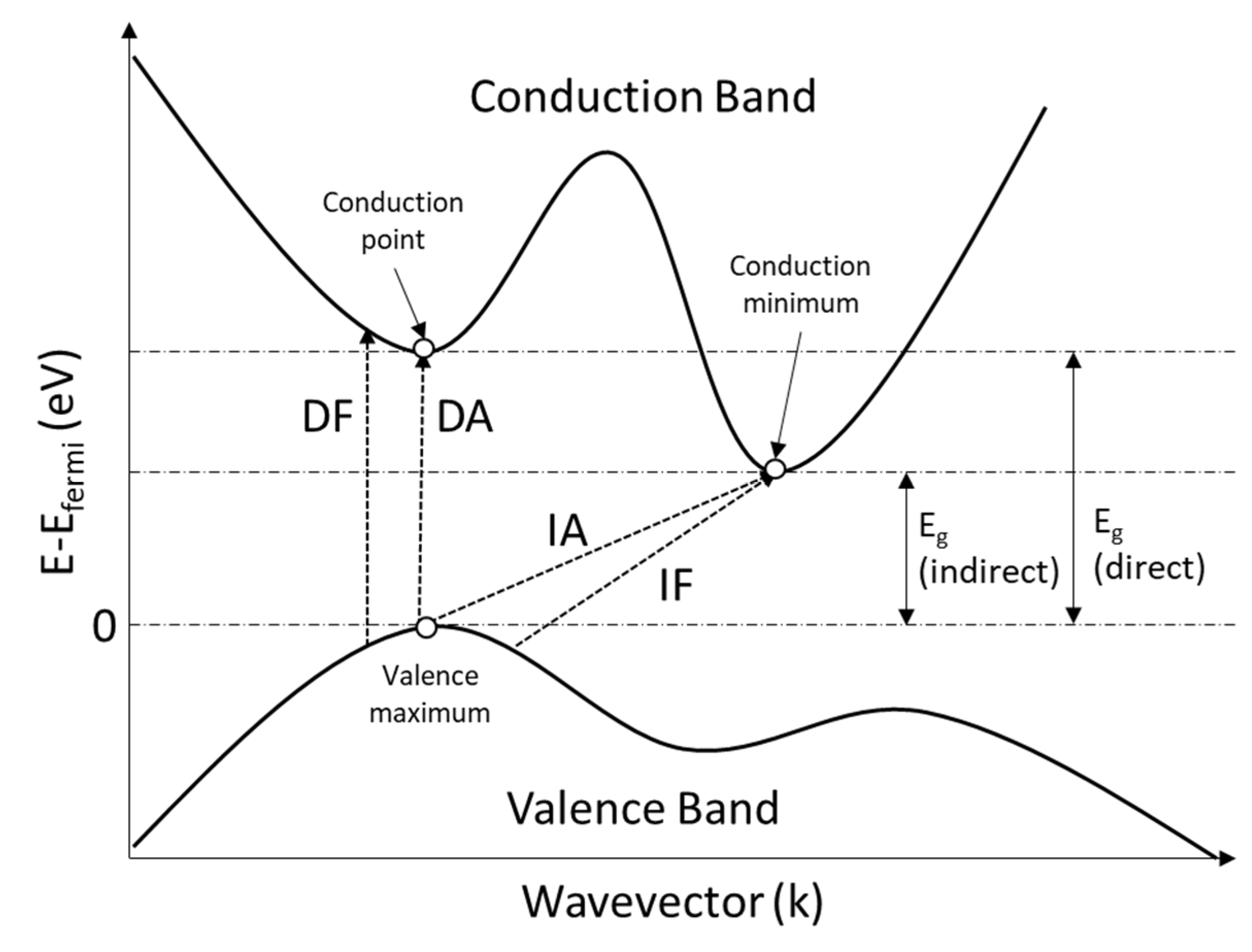
5.3. Optical Properties

The optical properties are the behaviour of materials when they are exposed to electromagnetic radiation (light). Glass-based materials are optically transparent, have a high light transmittance, a high reflectance (smooth surface), and a high optical density-dependent refraction. By contrast, glass–ceramics or ceramics-based materials mostly appear as opaque, and the light transmitted through them is nearly zero. When the material interacts with light, the predominant mechanism that occurs in the materials is electronic polarization and electron transition between different energy states.
Electronic polarization takes place during the electric field of light distorting the electron cloud in the material. The electronic polarization mechanism can be divided into two conversions: photon–phonon and photon–photon. In photon–phonon conversion, light energy is scattered and converted into elastic waves during the propagation through the materials. The produced elastic waves appear to be phonon vibration and, subsequently, generate heat. In photon–photon conversion, it involves a rapid light absorption and reemission at the same wavelength, which is known as reflection. As the energy levels of electrons are quantized and the ground state overlaps with the excited state, light provides the electrons with sufficient energy to shift from lower energy levels (ground state) to a higher energy levels (excited state). At the higher energy levels, electrons are unable to hold the energy for prolonged periods and instantly fall back to the ground state, emitting electromagnetic radiation at the same wavelength as the light energy supplied to the electrons. Figure 16 shows the possible phenomenon when ceramics interacts with light.
However, electronic polarization is not applicable to most ceramics, as there is a separation (capped at 4 eV) between the valence band and conduction band—the bandgap energy (Eg). Due to the remarkable Eg, the electronic transition in the ceramic is meaningful when it comes to application purposes. Eg is classified into direct and indirect, and the electronic transition is divided into allowed and forbidden transitions. The direct bandgap is a vertical transition (electron–photon interaction) at the same wavevector where the energy changes but the momentum is conserved, e.g., X-X transition; the indirect bandgap is an oblique transition (electron–photon–phonon interaction) at different wavevectors where the energy and the momentum change, e.g., X–Γ transition. The difference between the allowed and forbidden transitions is the momentum matrix element characterization: different from zero (allowed transition) and equals zero (forbidden transition). The sketched band structure of a material with an indirect bandgap is displayed in Figure 17. It shows that the direct Eg is larger than the indirect Eg, meaning that the material is capable of performing a direct band transition when the energy supplied is sufficient. Researchers have extensively applied CNTs to optical absorbance properties such as bandgap reduction to domain crystals. Table 10 shows previous studies in the literature of the application of CNTs in achieving ceramics with low bandgap applications.

5.4. Mechanical Properties

Introducing CNTs into CMCs to make a stronger ceramic composite is not a modern advancement but it has been developed decades ago. Previous studies in the literature have shown the effect of CNTs on the enhancement of mechanical properties when CNTs are dispersed and densified with appropriate techniques with optimized CNTs compositions. Generally, the CNTs-CMCs mechanical properties enhancement refer to the increase in fracture toughness (KIC), flexural strength, and Young’s modulus, upon low CNTs addition. The KIC of the CNTs-CMCs was mainly estimated by measuring the crack lengths from the Vickers indentation (also known as the indentation fracture indention technique) [120,136,162,163] and single-edge notched beam (SENB) method [51,164,165,166]. For CNTs-CMCs materials, the Evans and Charles equation [167] is widely used to estimate the KIC from the crack length, which is shown in Equation (3):
K I C = 0.0752 P c 3 / 2
where P is the applied load and c is the radial crack length.
The lack of CNT pullout from the CMCs and CNTs bridging caused the Vicker’s surface hardness (HV) and the ρ% of the CNTs-CMCs to not show significant improvements, and they increased the risk of mechanical defects such as a low KIC and low bending strength [166] (see Figure 18). Table 11 displays the recent works (dispersion, densification, sintering, and optimized CNTs composition) of the CNTs-CMCs compared with the CNT-free CMCs to illustrate the improvement from the mechanical perspectives.

6. Summary and Outlook

The present review article aimed to provide an overview of the critical challenges, the recent breakthroughs on the dispersion and densification and sintering routes, and the enhanced characteristics of the CNTS-reinforced ceramic matrix composites. CNTs have strengthened the ceramic matrix composites in many aspects such as density, fracture toughness, thermal conductivity, and wear resistance, while only a low amount of CNTs reinforcement is needed. Those beneficial properties could be improved or perfected if the CNT fillers are distributed homogenously within the domain matrices, and the agglomeration issue has thrived. With such fascinating properties, CNTs should have improved the CMCs’ functional properties linearly or exponentially with the increase in CNT fillers. However, most research on the CNTs-CMCs has resulted in an “optimum” addition of CNTs for the best CMCs’ performance due to the CNTs agglomeration at a large CNTs amount in the matrix.
To counter these issues, researchers have investigated the processing techniques and densification and sintering routes of CNTs-CMCs, such as the sol–gel processing and SPS, to maximize the functional properties. Every mentioned processing technique (Section 3) and densification and sintering route (Section 4) has its pros and cons in the perspective of the techniques’ complexity, duration, energy consumption, and the starting materials (see Table 12 and Table 13). All these pros-cons considerations are the parameters that determine the CNTs distribution, interfacial adhesion between CNTs and the domain ceramic, and the thermal stability and the sinterability of CNTs-CMCs. The desired properties of the CNTs-CMCs end-products are also the main concerns during the fabrication process. Still, many studies maintain the momentum to optimize the existing CNTs-CMCs fabrication processes, discover novel fabrication methods, and evaluate the final composites’ performance from the microstructural properties to the functional properties before commercializing them. We addressed the fundamental insights for the future technological maturation and advancement of CNTs-CMCs.

Author Contributions

Conceptualization, K.F.C. and Y.Y.; methodology, K.F.C., M.H.M.Z. and Y.Y.; validation, K.F.C., M.H.M.Z., M.S.M., S.L., M.T. and Y.Y.; resources, K.F.C., M.H.M.Z. and Y.Y.; data curation, K.F.C., S.L. and Y.Y.; writing—original draft preparation, K.F.C.; writing—review and editing, K.F.C., M.H.M.Z., M.S.M., S.L., M.T. and Y.Y.; supervision, M.H.M.Z., M.S.M. and Y.Y.; project administration, Y.Y.; funding acquisition, Y.Y. All authors have read and agreed to the published version of the manuscript.

Funding

This research was supported by the Malaysia Ministry of Higher Education (MoHE) through a Fundamental Research Grant Scheme (FRGS/1/2018/STG07/UPM/02/3) No. 5540132.

Data Availability Statement

No new data were created or analyzed in this study. Data sharing is not applicable to this article.

Acknowledgments

The authors would like to thank the support from the Department of Physics, University Putra Malaysia, MoHE (FRGS/1/2018/STG7/UPM/02/3), and the Nanotechnology Platform, Nagoya Institute of Technology.

Conflicts of Interest

The authors declare no conflict of interest.

Abbreviations

CCECarbon ceramic electrode
CMCsCeramic matrix composites
CNTsCarbon nanotubes
CNTs-CMCsCarbon nanotube-incorporated ceramic matrix composites
CVDChemical vapour deposition
DThermal diffusivity
EGEthylene glycol
EgOptical band gap energy
HNO3Nitric acid
HPSHot-press sintering
HVVicker’s surface hardness
KICFracture toughness
MASMicrowave-assisted sintering
MWCNTMulti-walled carbon nanotube
PLSPressureless sintering
PVPPolyvinyl pyrrolidone
SPSSpark plasma sintering
SWCNTSingle-walled carbon nanotube
κthThermal conductivity
ρ%Relative density

References

  1. Li, F.; Huang, X.; Liu, J.X.; Zhang, G.J. Sol–gel derived porous ultra-high temperature ceramics. J. Adv. Ceram. 2020, 9, 1–16. [Google Scholar] [CrossRef] [Green Version]
  2. Gorni, G.; Velázquez, J.J.; Mosa, J.; Balda, R.; Fernández, J.; Durán, A.; Castro, Y. Transparent glass-ceramics produced by Sol–Gel: A suitable alternative for photonic materials. Materials 2018, 11, 212. [Google Scholar] [CrossRef] [PubMed] [Green Version]
  3. Fiocco, L.; Ferroni, L.; Gardin, C.; Zavan, B.; Secco, M.; Matthews, S.; Bernardo, E. Wollastonite-diopside glass-ceramic foams from supercritical carbon dioxide-assisted extrusion of a silicone resin and inorganic fillers. J. Non Cryst. Solids 2016, 443, 33–38. [Google Scholar] [CrossRef]
  4. Okada, K.; Hayashi, H.; Takesue, M.; Watanabe, M.; Smith, R.L. Synthesis of ferroelectric K1−xNaxNb1−yTayO3 nanoparticles using a supercritical water flow system. J. Supercrit. Fluids 2017, 123, 101–108. [Google Scholar] [CrossRef]
  5. Cheong, H.G.; Chu, C.N.; Kwon, K.K.; Song, K.Y. Micro-structuring silicon compound ceramics using nanosecond pulsed laser assisted by hydrothermal reaction. J. Manuf. Process. 2020, 50, 34–46. [Google Scholar] [CrossRef]
  6. Reka, A.A.; Pavlovski, B.; Makreski, P. New optimized method for low-temperature hydrothermal production of porous ceramics using diatomaceous earth. Ceram. Int. 2017, 43, 12572–12578. [Google Scholar] [CrossRef]
  7. Ramesh, S.; Sara Lee, K.Y.; Tan, C.Y. A review on the hydrothermal ageing behaviour of Y-TZP ceramics. Ceram. Int. 2018, 44, 20620–20634. [Google Scholar] [CrossRef]
  8. Palakurthy, S.; Azeem, P.A.; Venugopal Reddy, K.; Penugurti, V.; Manavathi, B. A comparative study on in vitro behavior of calcium silicate ceramics synthesized from biowaste resources. J. Am. Ceram. Soc. 2020, 103, 933–943. [Google Scholar] [CrossRef]
  9. Devi, K.B.; Lee, B.; Roy, A.; Kumta, P.N.; Roy, M. Effect of zinc oxide doping on in vitro degradation of magnesium silicate bioceramics. Mater. Lett. 2017, 207, 100–103. [Google Scholar] [CrossRef]
  10. Fu, S.; Zhu, M.; Zhu, Y. Organosilicon polymer-derived ceramics: An overview. J. Adv. Ceram. 2019, 8, 457–478. [Google Scholar] [CrossRef] [Green Version]
  11. Song, Y.; He, L.; Zhang, X.; Liu, F.; Tian, N.; Tang, Y.; Kong, J. Highly efficient electromagnetic wave absorbing metal-free and carbon-rich ceramics derived from hyperbranched polycarbosilazanes. J. Phys. Chem. C 2017, 121. [Google Scholar] [CrossRef]
  12. Iijima, S. Helical microtubules of graphitic carbon. Nature 1991, 354, 56–58. [Google Scholar] [CrossRef]
  13. Trojanowicz, M. Analytical applications of carbon nanotubes: A review. TrAC Trends Anal. Chem. 2006, 25, 480–489. [Google Scholar] [CrossRef]
  14. AfzaliTabar, M.; Alaei, M.; Ranjineh Khojasteh, R.; Motiee, F.; Rashidi, A.M. Preference of multi-walled carbon nanotube (MWCNT) to single-walled carbon nanotube (SWCNT) and activated carbon for preparing silica nanohybrid pickering emulsion for chemical enhanced oil recovery (C-EOR). J. Solid State Chem. 2017, 245, 164–173. [Google Scholar] [CrossRef]
  15. Nadeem, S.; Khan, A.U.; Hussain, S.T. Model based study of SWCNT and MWCNT thermal conductivities effect on the heat transfer due to the oscillating wall conditions. Int. J. Hydrogen Energy 2017, 42, 28945–28957. [Google Scholar] [CrossRef]
  16. Cao, R.; Chen, S.; Wang, Y.; Han, N.; Liu, H.; Zhang, X. Functionalized carbon nanotubes as phase change materials with enhanced thermal, electrical conductivity, light-to-thermal, and electro-to-thermal performances. Carbon 2019, 149, 263–272. [Google Scholar] [CrossRef]
  17. Guo, T.; Nikolaev, P.; Rinzler, A.G.; Tomanek, D.; Colbert, D.T.; Smalley, R.E. Self-assembly of tubular fullerenes. J. Phys. Chem. 1995, 99, 10694–10697. [Google Scholar] [CrossRef]
  18. Fonseca, A.; Hernadi, K.; Nagy, J.B.; Bernaerts, D.; Lucas, A.A. Optimization of catalytic production and purification of buckytubes. J. Mol. Catal. A Chem. 1996, 107, 159–168. [Google Scholar] [CrossRef]
  19. Nikolaev, P.; Bronikowski, M.J.; Bradley, R.K.; Rohmund, F.; Colbert, D.T.; Smith, K.A.; Smalley, R.E. Gas-phase catalytic growth of single-walled carbon nanotubes from carbon monoxide. Chem. Phys. Lett. 1999, 313, 91–97. [Google Scholar] [CrossRef]
  20. Kumar, D.; Singh, K.; Verma, V.; Bhatti, H.S. Investigation of optical properties of pristine and functionalized single-walled carbon nanotubes. J. Mater. Sci. Mater. Electron. 2015, 26, 2117–2126. [Google Scholar] [CrossRef]
  21. Dresselhaus, M.S.; Dresselhaus, G.; Charlier, J.C.; Hernández, E. Electronic, thermal and mechanical properties of carbon nanotubes. Philos. Trans. R. Soc. Lond. Ser. A Math. Phys. Eng. Sci. 2004, 362, 2065–2098. [Google Scholar] [CrossRef]
  22. Wang, Q.; Liew, K.M. Mechanical properties of carbon nanotubes. Carbon Nanotub. New Res. 2009, 260, 157–174. [Google Scholar] [CrossRef] [Green Version]
  23. Kim, Y.A.; Muramatsu, H.; Hayashi, T.; Endo, M.; Terrones, M.; Dresselhaus, M.S. Thermal stability and structural changes of double-walled carbon nanotubes by heat treatment. Chem. Phys. Lett. 2004, 398, 87–92. [Google Scholar] [CrossRef]
  24. Aliev, A.E.; Lima, M.H.; Silverman, E.M.; Baughman, R.H. Thermal conductivity of multi-walled carbon nanotube sheets: Radiation losses and quenching of phonon modes. Nanotechnology 2010, 21. [Google Scholar] [CrossRef]
  25. Leahu, G.; Li Voti, R.; Larciprete, M.C.; Sibilia, C.; Bertolotti, M.; Nefedov, I.; Anoshkin, I.V. Thermal Characterization of Carbon Nanotubes by Photothermal Techniques. Int. J. Thermophys. 2015, 36, 1349–1357. [Google Scholar] [CrossRef]
  26. Tzounis, L.; Zappalorto, M.; Panozzo, F.; Tsirka, K.; Maragoni, L.; Paipetis, A.S.; Quaresimin, M. Highly conductive ultra-sensitive SWCNT-coated glass fiber reinforcements for laminate composites structural health monitoring. Compos. Part B Eng. 2019, 169, 37–44. [Google Scholar] [CrossRef]
  27. Subhani, T.; Shaffer, M.S.P.; Boccaccini, A.R. Carbon nanotube (CNT) reinforced glass and glass-ceramic matrix composites. In Ceramic Nanocomposites; Woodhead Publishing: Cambridge, UK, 2013; ISBN 9780857093387. [Google Scholar]
  28. Abazari, S.; Shamsipur, A.; Bakhsheshi-Rad, H.R.; Ismail, A.F.; Sharif, S.; Razzaghi, M.; Ramakrishna, S.; Berto, F. Carbon nanotubes (CNTs)-reinforced magnesium-based matrix composites: A comprehensive review. Materials 2020, 13, 4421. [Google Scholar] [CrossRef] [PubMed]
  29. Chen, J.; Yan, L.; Song, W.; Xu, D. Interfacial characteristics of carbon nanotube-polymer composites: A review. Compos. Part A Appl. Sci. Manuf. 2018, 114, 149–169. [Google Scholar] [CrossRef]
  30. Huang, S.J.; Abbas, A.; Ballóková, B. Effect of CNT on microstructure, dry sliding wear and compressive mechanical properties of AZ61 magnesium alloy. J. Mater. Res. Technol. 2019, 8, 4273–4286. [Google Scholar] [CrossRef]
  31. Eatemadi, A.; Daraee, H.; Karimkhanloo, H.; Kouhi, M.; Zarghami, N.; Akbarzadeh, A.; Abasi, M.; Hanifehpour, Y.; Joo, S.W. Carbon nanotubes: Properties, synthesis, purification, and medical applications. Nanoscale Res. Lett. 2014, 9, 1–13. [Google Scholar] [CrossRef] [Green Version]
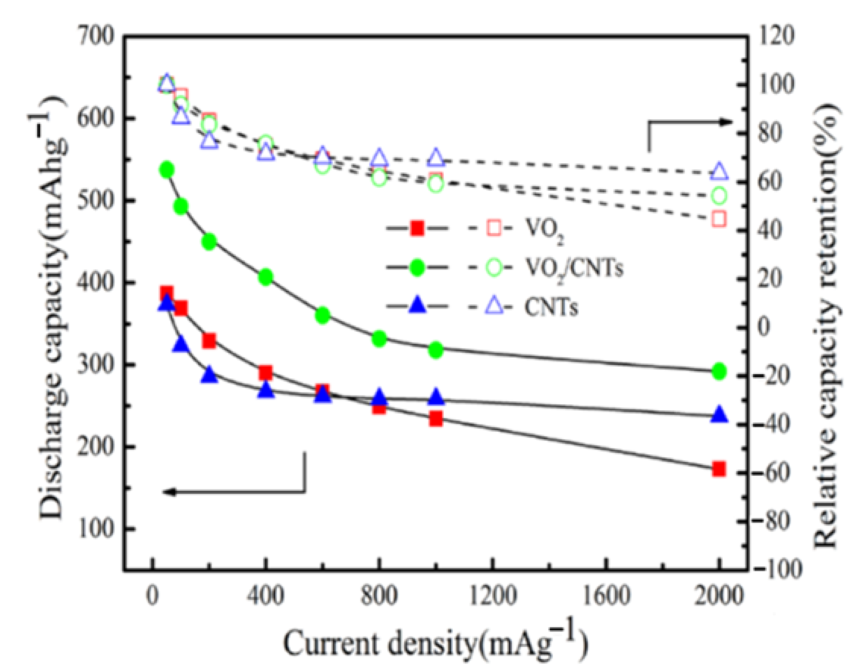
  32. Xiao, B.; Zhang, B.; Zheng, J.C.; Tang, L.B.; An, C.S.; He, Z.J.; Tong, H.; Yu, W.J. Nano-micro structure VO2/CNTs composite as a potential anode material for lithium ion batteries. Ceram. Int. 2018, 44, 13113–13121. [Google Scholar] [CrossRef]
  33. Peng, T.; Zeng, P.; Ke, D.; Liu, X.; Zhang, X. Hydrothermal Preparation of Multiwalled Carbon Nanotubes (MWCNTs)/CdS Nanocomposite and Its Efficient Photocatalytic Hydrogen Production under Visible Light Irradiation. Energy Fuels 2011, 25, 2203–2210. [Google Scholar] [CrossRef]
  34. Chen, L.; Zhao, J.; Wang, L.; Peng, F.; Liu, H.; Zhang, J.; Gu, J.; Guo, Z. In-situ pyrolyzed polymethylsilsesquioxane multi-walled carbon nanotubes derived ceramic nanocomposites for electromagnetic wave absorption. Ceram. Int. 2019, 45, 11756–11764. [Google Scholar] [CrossRef]
  35. Bazli, L.; Siavashi, M.; Shiravi, A. A Review of Carbon nanotube/TiO2 Composite prepared via Sol–Gel method. J. Compos. Compd. 2019, 1, 1–12. [Google Scholar] [CrossRef]
  36. Gao, C.; Feng, P.; Peng, S.; Shuai, C. Carbon nanotube, graphene and boron nitride nanotube reinforced bioactive ceramics for bone repair. Acta Biomater. 2017, 61, 1–20. [Google Scholar] [CrossRef]
  37. Jin, X.; Fan, X.; Lu, C.; Wang, T. Advances in oxidation and ablation resistance of high and ultra-high temperature ceramics modified or coated carbon/carbon composites. J. Eur. Ceram. Soc. 2018, 38, 1–28. [Google Scholar] [CrossRef]
  38. Lamnini, S.; Károly, Z.; Bódis, E.; Balázsi, K.; Balázsi, C. Influence of structure on the hardness and the toughening mechanism of the sintered 8YSZ/MWCNTs composites. Ceram. Int. 2019, 45, 5058–5065. [Google Scholar] [CrossRef]
  39. Jambagi, S.C.; Kar, S.; Brodard, P.; Bandyopadhyay, P.P. Characteristics of plasma sprayed coatings produced from carbon nanotube doped ceramic powder feedstock. Mater. Des. 2016, 112, 392–401. [Google Scholar] [CrossRef]
  40. Wei, H.; Yin, X.; Li, X.; Li, M.; Dang, X.; Zhang, L.; Cheng, L. Controllable synthesis of defective carbon nanotubes/Sc2Si2O7 ceramic with adjustable dielectric properties for broadband high-performance microwave absorption. Carbon 2019, 147, 276–283. [Google Scholar] [CrossRef]
  41. Li, H.; Song, X.; Li, B.; Kang, J.; Liang, C.; Wang, H.; Yu, Z.; Qiao, Z. Carbon nanotube-reinforced mesoporous hydroxyapatite composites with excellent mechanical and biological properties for bone replacement material application. Mater. Sci. Eng. C 2017, 77, 1078–1087. [Google Scholar] [CrossRef] [PubMed]
  42. Rubel, R.I.; Ali, M.H.; Jafor, M.A.; Alam, M.M. Carbon nanotubes agglomeration in reinforced composites: A review. AIMS Mater. Sci. 2019, 6, 756–780. [Google Scholar] [CrossRef]
  43. Lanfant, B.; Leconte, Y.; Debski, N.; Bonnefont, G.; Pinault, M.; Mayne-L′Hermite, M.; Habert, A.; Jorand, Y.; Garnier, V.; Fantozzi, G.; et al. Mechanical, thermal and electrical properties of nanostructured CNTs/SiC composites. Ceram. Int. 2019, 45, 2566–2575. [Google Scholar] [CrossRef]
  44. Rivero-Antúnez, P.; Cano-Crespo, R.; Esquivias, L.; de la Rosa-Fox, N.; Zamora-Ledezma, C.; Domínguez-Rodríguez, A.; Morales-Flórez, V. Mechanical characterization of sol–gel alumina-based ceramics with intragranular reinforcement of multiwalled carbon nanotubes. Ceram. Int. 2020, 46, 19723–19730. [Google Scholar] [CrossRef]
  45. Singh, S.; Sharma, S.; Singh, R.C.; Sharma, S. Hydrothermally synthesized MoS2-multi-walled carbon nanotube composite as a novel room-temperature ammonia sensing platform. Appl. Surf. Sci. 2020, 532, 147373. [Google Scholar] [CrossRef]
  46. Shahabuddin, M.; Madhar, N.A.; Alzayed, N.S.; Asif, M. Uniform dispersion and exfoliation of multi-walled carbon nanotubes in CNT-MgB2 superconductor composites using surfactants. Materials 2019, 12, 3044. [Google Scholar] [CrossRef] [PubMed] [Green Version]
  47. Lin, J.; Yang, Y.; Zhang, H.; Lin, Q.; Zhu, B. Synthesis and characterization of in-situ CNTs reinforced TiB2-based composite by CVD using Ni catalysts. Ceram. Int. 2018, 44, 2042–2047. [Google Scholar] [CrossRef]
  48. Zhang, X.; Li, S.; Pan, B.; Pan, D.; Liu, L.; Hou, X.; Chu, M.; Kondoh, K.; Zhao, M. Regulation of interface between carbon nanotubes-aluminum and its strengthening effect in CNTs reinforced aluminum matrix nanocomposites. Carbon 2019, 155, 686–696. [Google Scholar] [CrossRef]
  49. Nor, A.F.M.; Sultan, M.T.H.; Jawaid, M.; Azmi, A.M.R.; Shah, A.U.M. Analysing impact properties of CNT filled bamboo/glass hybrid nanocomposites through drop-weight impact testing, UWPI and compression-after-impact behaviour. Compos. Part B Eng. 2019, 168, 166–174. [Google Scholar] [CrossRef]
  50. Kamalakaran, R.; Lupo, F.; Grobert, N.; Scheu, T.; Jin-Phillipp, N.Y.; Rühle, M. Microstructural characterization of C-SiC-carbon nanotube composite flakes. Carbon 2004, 42, 1–4. [Google Scholar] [CrossRef]
  51. Sharma, N.; Alam, S.N.; Ray, B.C.; Yadav, S.; Biswas, K. Silica-graphene nanoplatelets and silica-MWCNT composites: Microstructure and mechanical properties. Diam. Relat. Mater. 2018, 87, 186–201. [Google Scholar] [CrossRef]
  52. Xiao, B.; Zhang, W.H.; Xia, H.F.; Wang, Z.T.; Tang, L.B.; An, C.S.; He, Z.J.; Tong, H.; Zheng, J.C. V2(PO4)O/C@CNT hollow spheres with a core-shell structure as a high performance anode material for lithium-ion batteries. Mater. Chem. Front. 2019, 3, 456–463. [Google Scholar] [CrossRef]
  53. Javed, H.; Islam, M.; Mahmood, N.; Achour, A.; Hameed, A.; Khatri, N. Catalytic growth of multi-walled carbon nanotubes using NiFe2O4 nanoparticles and incorporation into epoxy matrix for enhanced mechanical properties. J. Polym. Eng. 2016, 36, 53–64. [Google Scholar] [CrossRef]
  54. Theodore, M.; Hosur, M.; Thomas, J.; Jeelani, S. Influence of functionalization on properties of MWCNT-epoxy nanocomposites. Mater. Sci. Eng. A 2011, 528, 1192–1200. [Google Scholar] [CrossRef]
  55. Shende, R.C.; Ramaprabhu, S. Thermo-optical properties of partially unzipped multiwalled carbon nanotubes dispersed nanofluids for direct absorption solar thermal energy systems. Sol. Energy Mater. Sol. Cells 2016, 157, 117–125. [Google Scholar] [CrossRef]
  56. Verma, V.; Galaveen, S.C.; Gurnani, L.; Venkateswaran, T.; Mukhopadhyay, A. Development of oxidation resistant and mechanically robust carbon nanotube reinforced ceramic composites. Ceram. Int. 2020, 46, 21784–21789. [Google Scholar] [CrossRef]
  57. Al-Gharabli, S.; Hamad, E.; Saket, M.; El-Rub, Z.A.; Arafat, H.; Kujawski, W.; Kujawa, J. Advanced material-ordered nanotubular ceramic membranes covalently capped with single-wall carbon nanotubes. Materials 2018, 11, 739. [Google Scholar] [CrossRef] [Green Version]
  58. Rongli, X.; Bian, D.; Aradhyula, T.V.; Chavali, M.; Zhao, Y. Preparation and corrosion behavior studies of chemically bonded phosphate ceramic coating reinforced with modified multi-walled carbon nanotubes (MWCNTs). Int. J. Appl. Ceram. Technol. 2019, 16, 923–930. [Google Scholar] [CrossRef]
  59. Jiang, L.; Gao, L. Densified multiwalled carbon nanotubes-titanium nitride composites with enhanced thermal properties. Ceram. Int. 2008, 34, 231–235. [Google Scholar] [CrossRef]
  60. Suslova, E.; Savilov, S.; Egorov, A.; Shumyantsev, A.; Lunin, V. Carbon nanotube frameworks by spark plasma sintering. Microporous Mesoporous Mater. 2020, 293, 109807. [Google Scholar] [CrossRef]
  61. Ding, M.; Sahebgharani, N.; Musharavati, F.; Jaber, F.; Zalnezhad, E.; Yoon, G.H. Synthesis and properties of HA/ZnO/CNT nanocomposite. Ceram. Int. 2018, 44, 7746–7753. [Google Scholar] [CrossRef]
  62. Boulerouah, A.; Longuemart, S.; Hus, P.; Sahraoui, A.H. Thermal transport investigation in a CNTs/solid matrix composite. J. Phys. D Appl. Phys. 2013, 46, 055302. [Google Scholar] [CrossRef]
  63. Esawi, A.; Morsi, K. Dispersion of carbon nanotubes (CNTs) in aluminum powder. Compos. Part A Appl. Sci. Manuf. 2007, 38, 646–650. [Google Scholar] [CrossRef]
  64. Yoshio, S.; Tatami, J.; Wakihara, T.; Yamakawa, T.; Nakano, H.; Komeya, K.; Meguro, T. Effect of CNT quantity and sintering temperature on electrical and mechanical properties of CNT-dispersed Si3N4 ceramics. J. Ceram. Soc. Jpn. 2011, 119, 70–75. [Google Scholar] [CrossRef] [Green Version]
  65. Tatami, J.; Katashima, T.; Komeya, K.; Meguro, T.; Wakihara, T. Electrically conductive CNT-dispersed silicon nitride ceramics. J. Am. Ceram. Soc. 2005, 88, 2889–2893. [Google Scholar] [CrossRef]
  66. Mazaheri, M.; Mari, D.; Schaller, R.; Bonnefont, G.; Fantozzi, G. Processing of yttria stabilized zirconia reinforced with multi-walled carbon nanotubes with attractive mechanical properties. J. Eur. Ceram. Soc. 2011, 31, 2691–2698. [Google Scholar] [CrossRef]
  67. Venkateswarlu, M.; Ashok Kumar, M.; Hema Chandra Reddy, K. Thermal Behavior of Spark Plasma Sintered Ceramic Matrix-Based Nanocomposites. J. Bio-Tribo-Corrosion 2020, 6, 1–11. [Google Scholar] [CrossRef]
  68. Esawi, A.M.K.; Morsi, K.; Sayed, A.; Taher, M.; Lanka, S. The influence of carbon nanotube (CNT) morphology and diameter on the processing and properties of CNT-reinforced aluminium composites. Compos. Part A Appl. Sci. Manuf. 2011, 42, 234–243. [Google Scholar] [CrossRef]
  69. Popov, O.; Vleugels, J.; Zeynalov, E.; Vishnyakov, V. Reactive hot pressing route for dense ZrB2-SiC and ZrB2-SiC-CNT ultra-high temperature ceramics. J. Eur. Ceram. Soc. 2020, 301, 127065. [Google Scholar] [CrossRef]
  70. Ye, F.; Liu, L.; Wang, Y.; Zhou, Y.; Peng, B.; Meng, Q. Preparation and mechanical properties of carbon nanotube reinforced barium aluminosilicate glass-ceramic composites. Scr. Mater. 2006, 55, 911–914. [Google Scholar] [CrossRef]
  71. Chan, K.F.; Mohd Zaid, M.H.; Liza, S.; Matori, K.A.; Mamat, M.S.; Hazan, M.A.; Yaakob, Y. Effect of CNT on microstructural properties of Zn2SiO4/CNT composite via dry powder processing. Mater. Res. Express 2020, 7, 105601. [Google Scholar] [CrossRef]
  72. Li, J.; Lu, Y.; Ye, Q.; Cinke, M.; Han, J.; Meyyappan, M. Carbon nanotube sensors for gas and organic vapor detection. Nano Lett. 2003, 3, 929–933. [Google Scholar] [CrossRef]
  73. Gojny, F.H.; Nastalczyk, J.; Roslaniec, Z.; Schulte, K. Surface modified multi-walled carbon nanotubes in CNT/epoxy-composites. Chem. Phys. Lett. 2003, 370, 820–824. [Google Scholar] [CrossRef]
  74. Manzetti, S.; Andersen, O. A molecular dynamics study of nanoparticle-formation from bioethanol-gasoline blend emissions. Fuel 2016, 183, 55–63. [Google Scholar] [CrossRef]
  75. Lin, D.; Xing, B. Adsorption of phenolic compounds by carbon nanotubes: Role of aromaticity and substitution of hydroxyl groups. Environ. Sci. Technol. 2008, 42, 7254–7259. [Google Scholar] [CrossRef]
  76. Gotovac, S.; Honda, H.; Hattori, Y.; Takahashi, K.; Kanoh, H.; Kaneko, K. Effect of nanoscale curvature of single-walled carbon nanotubes on adsorption of polycyclic aromatic hydrocarbons. Nano Lett. 2007, 7, 583–587. [Google Scholar] [CrossRef] [PubMed]
  77. Sun, J.; Gao, L.; Li, W. Colloidal Processing of Carbon Nanotube/Alumina Composites. Chem. Mater. 2002, 14, 5169–5172. [Google Scholar] [CrossRef]
  78. Zhu, Y.F.; Shi, L.; Zhang, C.; Yang, X.Z.; Liang, J. Preparation and properties of alumina composites modified by electric field-induced alignment of carbon nanotubes. Appl. Phys. A Mater. Sci. Process. 2007, 89, 761–767. [Google Scholar] [CrossRef]
  79. Arvanitelis, C.; Jayaseelan, D.D.; Cho, J.; Boccaccini, A.R. Carbon nanotube–SiO2 composites by colloidal processing. Adv. Appl. Ceram. 2008, 107, 155–158. [Google Scholar] [CrossRef]
  80. Phuoc, T.X.; Massoudi, M.; Chen, R.H. Viscosity and thermal conductivity of nanofluids containing multi-walled carbon nanotubes stabilized by chitosan. Int. J. Therm. Sci. 2011, 50, 12–18. [Google Scholar] [CrossRef]
  81. Fadhillahanafi, N.M.; Leong, K.Y.; Risby, M.S. Stability and thermal conductivity characteristics of carbon nanotube based nanofluids. Int. J. Automot. Mech. Eng. 2013, 8, 1376–1384. [Google Scholar] [CrossRef]
  82. Jajja, S.A.; Ali, W.; Ali, H.M. Multiwalled carbon nanotube nanofluid for thermal management of high heat generating computer processor. Heat Transf. Asian Res. 2014, 43, 653–666. [Google Scholar] [CrossRef]
  83. Hordy, N.; Rabilloud, D.; Meunier, J.L.; Coulombe, S. A Stable Carbon Nanotube Nanofluid for Latent Heat-Driven Volumetric Absorption Solar Heating Applications. J. Nanomater. 2015, 2015. [Google Scholar] [CrossRef] [Green Version]
  84. Walvekar, R.; Siddiqui, M.K.; Ong, S.S.; Ismail, A.F. Application of CNT nanofluids in a turbulent flow heat exchanger. J. Exp. Nanosci. 2016, 11, 1–17. [Google Scholar] [CrossRef]
  85. Rashidi, S.; Rashmi, W.; Abdullah, L.C.; Khalid, M.; Ahmadun, F.R.; Faizah, M.Y. Thermal stability and conductivity of carbon nanotube nanofluid using xanthan gum as surfactant. Sains Malays. 2017, 46, 1017–1024. [Google Scholar] [CrossRef]
  86. Keinänen, P.; Siljander, S.; Koivula, M.; Sethi, J.; Sarlin, E.; Vuorinen, J.; Kanerva, M. Optimized dispersion quality of aqueous carbon nanotube colloids as a function of sonochemical yield and surfactant/CNT ratio. Heliyon 2018, 4. [Google Scholar] [CrossRef] [PubMed] [Green Version]
  87. Nasirzadehroshenin, F.; Sadeghzadeh, M.; Khadang, A.; Maddah, H.; Ahmadi, M.H.; Sakhaeinia, H.; Chen, L. Modeling of heat transfer performance of carbon nanotube nanofluid in a tube with fixed wall temperature by using ANN–GA. Eur. Phys. J. Plus 2020, 135. [Google Scholar] [CrossRef]
  88. Poon, R.; Liang, W.; Zhitomirsky, I. Mn3O4 and (ZnFe)OOH Composites for Supercapacitors with High Active Mass. Metall. Mater. Trans. A Phys. Metall. Mater. Sci. 2020, 51, 855–862. [Google Scholar] [CrossRef]
  89. Liu, Y.; Li, L.; Shi, J.; Han, R.; Wu, P.; Yue, X.; Zhou, Z.; Chen, G.X.; Li, Q. High dielectric constant composites controlled by a strontium titanate barrier layer on carbon nanotubes towards embedded passive devices. Chem. Eng. J. 2019, 373, 642–650. [Google Scholar] [CrossRef]
  90. Xu, R.; Bian, D.; Zhao, Y.; Xu, X.; Liu, Y.; Zhou, W. Tribological behavior studies of chemically bonded phosphate ceramic coatings reinforced with modified multi-walled carbon nanotubes (MWCNTs). Int. J. Appl. Ceram. Technol. 2020, 17, 1010–1016. [Google Scholar] [CrossRef]
  91. Roushani, M.; Karami, M.; Zare Dizajdizi, B. Amperometric NADH sensor based on a carbon ceramic electrode modified with the natural carotenoid crocin and multi-walled carbon nanotubes. Microchim. Acta 2017, 184, 473–481. [Google Scholar] [CrossRef]
  92. Schebeliski, A.H.; Lima, D.; Marchesi, L.F.Q.P.; Calixto, C.M.F.; Pessôa, C.A. Preparation and characterization of a carbon nanotube-based ceramic electrode and its potential application at detecting sulfonamide drugs. J. Appl. Electrochem. 2018, 48, 471–485. [Google Scholar] [CrossRef]
  93. Ferrag, C.; Noroozifar, M.; Kerman, K. Thiol functionalized carbon ceramic electrode modified with multi-walled carbon nanotubes and gold nanoparticles for simultaneous determination of purine derivatives. Mater. Sci. Eng. C 2020, 110, 110568. [Google Scholar] [CrossRef] [PubMed]
  94. Jafari, F.; Nasirizadeh, N.; Mirjalili, M. Enhanced degradation of reactive dyes using a novel carbon ceramic electrode based on copper nanoparticles and multiwall carbon nanotubes. Chin. J. Chem. Eng. 2020, 28, 318–327. [Google Scholar] [CrossRef]
  95. Mombeshora, E.T.; Simoyi, R.; Nyamori, V.O.; Ndungu, P.G. Multiwalled carbon nanotube-titania nanocomposites: Understanding nano-structural parameters and functionality in dye-sensitized solar cells. S. Afr. J. Chem. 2015, 68, 153–164. [Google Scholar] [CrossRef] [Green Version]
  96. Abbas, N.; Shao, G.N.; Haider, M.S.; Imran, S.M.; Park, S.S.; Jeon, S.J.; Kim, H.T. Inexpensive sol–gel synthesis of multiwalled carbon nanotube-TiO2 hybrids for high performance antibacterial materials. Mater. Sci. Eng. C 2016, 68, 780–788. [Google Scholar] [CrossRef]
  97. Pohl, M.; Kurig, H.; Tallo, I.; Jänes, A.; Lust, E. Novel sol–gel synthesis route of carbide-derived carbon composites for very high power density supercapacitors. Chem. Eng. J. 2017, 320, 576–587. [Google Scholar] [CrossRef]
  98. Li, W.; Ji, W.; Isfahani, F.T.; Wang, Y.; Li, G.; Liu, Y.; Xing, F. Nano-silica sol–gel and carbon nanotube coupling effect on the performance of cement-based materials. Nanomaterials 2017, 7, 185. [Google Scholar] [CrossRef] [Green Version]
  99. dos Santos, P.A.M.; de Oliveira Almeida, V.; Benvenutti, E.V.; Balzaretti, N.M.; Gallas, M.R.; Costa, T.M.H. High-grade MWCNT/ZrO2 composites prepared by sol–gel method and high-pressure technique (4.0 GPa): Mechanically resistant, porous, and conductive. J. Sol–Gel Sci. Technol. 2019, 90, 348–358. [Google Scholar] [CrossRef]
  100. Park, J.E.; Jang, Y.S.; Bae, T.S.; Lee, M.H. Biocompatibility characteristics of titanium coated with multiwalled carbon nanotubes-hydroxyapatite nanocomposites. Materials 2019, 12, 224. [Google Scholar] [CrossRef] [Green Version]
  101. Liu, Y.; Shi, J.; Kang, P.; Wu, P.; Zhou, Z.; Chen, G.-X.; Li, Q. Improve the dielectric property and breakdown strength of composites by cladding a polymer/BaTiO3 composite layer around carbon nanotubes. Polymer 2020, 188, 122157. [Google Scholar] [CrossRef]
  102. Chen, M.; Yin, X.; Li, M.; Chen, L.; Cheng, L.; Zhang, L. Electromagnetic interference shielding properties of silicon nitride ceramics reinforced by in situ grown carbon nanotubes. Ceram. Int. 2015, 41, 2467–2475. [Google Scholar] [CrossRef]
  103. Tofighy, M.A.; Mohammadi, T. Synthesis and characterization of ceramic/carbon nanotubes composite adsorptive membrane for copper ion removal from water. Korean J. Chem. Eng. 2015, 32, 292–298. [Google Scholar] [CrossRef]
  104. Ding, D.; Wang, J.; Xiao, G.; Li, Z.; Bai, B.; Ren, J.; He, G. Enhanced electromagnetic wave absorbing properties of Si-O-C ceramics with in-situ formed 1D nanostructures. Int. J. Appl. Ceram. Technol. 2020, 17, 734–744. [Google Scholar] [CrossRef]
  105. Rosenburg, F.; Ionescu, E.; Nicoloso, N.; Riedel, R. High-temperature Raman spectroscopy of nano-crystalline carbon in silicon oxycarbide. Materials 2018, 11, 93. [Google Scholar] [CrossRef] [PubMed] [Green Version]
  106. Caņado, L.G.; Takai, K.; Enoki, T.; Endo, M.; Kim, Y.A.; Mizusaki, H.; Jorio, A.; Coelho, L.N.; Magalhães-Paniago, R.; Pimenta, M.A. General equation for the determination of the crystallite size la of nanographite by Raman spectroscopy. Appl. Phys. Lett. 2006, 88, 1–4. [Google Scholar] [CrossRef]
  107. Mazumder, S.; Sarkar, N.; Park, J.G.; Han, I.S.; Kim, I.J. Carbon nanotubes-porous ceramic composite by in situ CCVD growth of CNTs. Mater. Chem. Phys. 2016, 171, 247–251. [Google Scholar] [CrossRef]
  108. Lin, J.; Yang, Y.; Zhang, H.; Su, B.; Yang, Y. Optimization of CNTs growth on TiB2-based composite powders by CVD with Fe as catalyst. Ceram. Int. 2020, 46, 3837–3843. [Google Scholar] [CrossRef]
  109. Zhao, G.; Zhang, D.; Yu, J.; Xie, Y.; Hu, W.; Jiao, F. Multi-walled carbon nanotubes modified Bi2S3 microspheres for enhanced photocatalytic decomposition efficiency. Ceram. Int. 2017, 43, 15080–15088. [Google Scholar] [CrossRef]
  110. Li, L.; Sun, Q.; Chen, X.; Jiang, Z.; Xu, Y. Significantly improved dielectric performance of poly(1-butene)-based composite films via filling polydopamine modified Ba(Zr0.2Ti0.8)O3-coated multiwalled carbon nanotubes nanoparticles. Polymers 2021, 13, 285. [Google Scholar] [CrossRef]
  111. Vadivel, S.; Naveen, A.N.; Theerthagiri, J.; Madhavan, J.; Santhoshini Priya, T.; Balasubramanian, N. Solvothermal synthesis of BiPO4 nanorods/MWCNT (1D-1D) composite for photocatalyst and supercapacitor applications. Ceram. Int. 2016, 42, 14196–14205. [Google Scholar] [CrossRef]
  112. Zhang, X.; Hao, L. Preparation and Catalytic Activity of M2O3/CNTs (M = Y, Nd, Sm) Nanocomposites by Solvothermal Process. J. Nanomater. 2018, 2018. [Google Scholar] [CrossRef] [Green Version]
  113. Khan, M.; Yousaf, A.B.; Chen, M.; Wei, C.; Wu, X.; Huang, N.; Qi, Z.; Li, L. Molybdenum sulfide/graphene-carbon nanotube nanocomposite material for electrocatalytic applications in hydrogen evolution reactions. Nano Res. 2016, 9, 837–848. [Google Scholar] [CrossRef]
  114. Naoi, K.; Kurita, T.; Abe, M.; Furuhashi, T.; Abe, Y.; Okazaki, K.; Miyamoto, J.; Iwama, E.; Aoyagi, S.; Naoi, W.; et al. Ultrafast Nanocrystalline-TiO2(B)/Carbon Nanotube Hyperdispersion Prepared via Combined Ultracentrifugation and Hydrothermal Treatments for Hybrid Supercapacitors. Adv. Mater. 2016, 28, 6751–6757. [Google Scholar] [CrossRef] [Green Version]
  115. Jiang, L.; Qiu, Y.; Luo, P.; Yu, Y. Nickel hydroxide-impregnated and -coated carbon nanotubes using an easily manipulated solvothermal route for supercapacitors. Ceram. Int. 2016, 42, 11634–11639. [Google Scholar] [CrossRef]
  116. Munir, Z.A.; Anselmi-Tamburini, U.; Ohyanagi, M. The effect of electric field and pressure on the synthesis and consolidation of materials: A review of the spark plasma sintering method. J. Mater. Sci. 2006, 41, 763–777. [Google Scholar] [CrossRef]
  117. Zhan, G.D.; Kuntz, J.D.; Wan, J.; Mukherjee, A.K. Single-wall carbon nanotubes as attractive toughening agents in alumina-based nanocomposites. Nat. Mater. 2003, 2, 38–42. [Google Scholar] [CrossRef]
  118. Zhan, G.D.; Kuntz, J.D.; Garay, J.E.; Mukherjee, A.K. Electrical properties of nanoceramics reinforced with ropes of single-walled carbon nanotubes. Appl. Phys. Lett. 2003, 83, 1228–1230. [Google Scholar] [CrossRef]
  119. Momohjimoh, I.; Saheb, N.; Hussein, M.A.; Laoui, T.; Al-Aqeeli, N. Electrical conductivity of spark plasma sintered Al2O3–SiC and Al2O3-carbon nanotube nanocomposites. Ceram. Int. 2020, 46, 16008–16019. [Google Scholar] [CrossRef]
  120. Karthiselva, N.S.; Bakshi, S.R. Carbon nanotube and in-situ titanium carbide reinforced titanium diboride matrix composites synthesized by reactive spark plasma sintering. Mater. Sci. Eng. A 2016, 663, 38–48. [Google Scholar] [CrossRef]
  121. Barmin, A.; Bortnikova, V.; Ivanov, A.; Kornev, V.; Lurie, S.; Solyaev, Y. Microstructure and mechanical properties of silicon carbide ceramics reinforced with multi-walled carbon nanotubes. IOP Conf. Ser. Mater. Sci. Eng. 2016, 124. [Google Scholar] [CrossRef] [Green Version]
  122. Delbari, S.A.; Nayebi, B.; Ghasali, E.; Shokouhimehr, M.; Shahedi Asl, M. Spark plasma sintering of TiN ceramics codoped with SiC and CNT. Ceram. Int. 2019, 45, 3207–3216. [Google Scholar] [CrossRef]
  123. Cheng, C.; Wu, Y.; Qu, Y.; Ma, R.; Fan, R. Radio-frequency negative permittivity of carbon nanotube/copper calcium titanate ceramic nanocomposites fabricated by spark plasma sintering. Ceram. Int. 2020, 46, 2261–2267. [Google Scholar] [CrossRef]
  124. Wang, J.; Kou, H.; Liu, X.; Pan, Y.; Guo, J. Reinforcement of mullite matrix with multi-walled carbon nanotubes. Ceram. Int. 2007, 33, 719–722. [Google Scholar] [CrossRef]
  125. Yuan, G.; Li, Y.; Long, X.; Cui, Z.; Dong, Z.; Cong, Y.; Zhang, J.; Li, X. Tuning anisotropic thermal conductivity of unidirectional carbon/carbon composites by incorporating carbonaceous fillers. J. Mater. Sci. 2020, 55, 5079–5098. [Google Scholar] [CrossRef]
  126. Ding, C.; Gan, W.; Hu, X.; Wu, K.; Wang, X. Investigation into the influence of carbon nanotubes addition on residual stresses and mechanical properties in the CNTs@SiCp/Mg-6Zn hybrid composite using neutron diffraction method. Mater. Sci. Eng. A 2020, 797, 140105. [Google Scholar] [CrossRef]
  127. Saleem, A.; Zhang, Y.; Gong, H.; Majeed, M.K.; Ashfaq, M.Z.; Jing, J.; Lin, X.; Sheng, M. Carbon nanostructure-reinforced SiCw/Si3N4 composite with enhanced thermal conductivity and mechanical properties. RSC Adv. 2020, 10, 15023–15029. [Google Scholar] [CrossRef] [Green Version]
  128. Pelleg, J. Mechanism of diffusion. Solid Mech. Its Appl. 2016, 221, 31–39. [Google Scholar] [CrossRef]
  129. Ahmad, I.; Islam, M.; Dar, M.A.; Xu, F.; Shah, S.I.; Zhu, Y. Magnesia tuned multi-walled carbon nanotubes-reinforced alumina nanocomposites. Mater. Charact. 2015, 99, 210–219. [Google Scholar] [CrossRef]
  130. Abden, M.J.; Afroze, J.D.; Alam, M.S.; Bahadur, N.M. Pressureless sintering and mechanical properties of hydroxyapatite/functionalized multi-walled carbon nanotube composite. Mater. Sci. Eng. C 2016, 67, 418–424. [Google Scholar] [CrossRef] [PubMed]
  131. Muccillo, R.; Ferlauto, A.S.; Muccillo, E.N.S. Flash Sintering Samaria-Doped Ceria–Carbon Nanotube Composites. Ceramics 2019, 2, 64–73. [Google Scholar] [CrossRef] [Green Version]
  132. Boccaccini, A.R.; Acevedo, D.R.; Brusatin, G.; Colombo, P. Borosilicate glass matrix composites containing multi-wall carbon nanotubes. J. Eur. Ceram. Soc. 2005, 25, 1515–1523. [Google Scholar] [CrossRef]
  133. Zhang, S.C.; Fahrenholtz, W.G.; Hilmas, G.E.; Yadlowsky, E.J. Pressureless sintering of carbon nanotube-Al2O3 composites. J. Eur. Ceram. Soc. 2010, 30, 1373–1380. [Google Scholar] [CrossRef]
  134. Bakhsh, N.; Khalid, F.A.; Hakeem, A.S. Synthesis and characterization of pressureless sintered carbon nanotube reinforced alumina nanocomposites. Mater. Sci. Eng. A 2013, 578, 422–429. [Google Scholar] [CrossRef]
  135. Aguilar-Elguézabal, A.; Bocanegra-Bernal, M.H. Fracture behaviour of α-Al2O3 ceramics reinforced with a mixture of single-wall and multi-wall carbon nanotubes. Compos. Part B Eng. 2014, 60, 463–470. [Google Scholar] [CrossRef]
  136. Bocanegra-Bernal, M.H.; Dominguez-Rios, C.; Echeberria, J.; Reyes-Rojas, A.; Garcia-Reyes, A.; Aguilar-Elguezabal, A. Effect of low-content of carbon nanotubes on the fracture toughness and hardness of carbon nanotube reinforced alumina prepared by sinter, HIP and sinter + HIP routes. Mater. Res. Express 2017, 4. [Google Scholar] [CrossRef]
  137. Li, Q.; Zheng, Y.; Xia, J.; Jiang, D. Structure and characteristics of carbon nanotube reinforced SiC composite. Key Eng. Mater. 2017, 726, 127–131. [Google Scholar] [CrossRef]
  138. Wang, Y.; Iqbal, Z.; Mitra, S. Rapid, low temperature microwave synthesis of novel carbon nanotube-silicon carbide composite. Carbon 2006, 44, 2804–2808. [Google Scholar] [CrossRef]
  139. Bhandavat, R.; Kuhn, W.; Mansfield, E.; Lehman, J.; Singh, G. Synthesis of polymer-derived ceramic Si(B)CN-carbon nanotube composite by microwave-induced interfacial polarization. ACS Appl. Mater. Interfaces 2012, 4, 11–16. [Google Scholar] [CrossRef]
  140. Abbaspour, A.; Ghaffarinejad, A. Preparation of a sol–gel-derived carbon nanotube ceramic electrode by microwave irradiation and its application for the determination of adenine and guanine. Electrochim. Acta 2010, 55, 1090–1096. [Google Scholar] [CrossRef]
  141. Ghobadi, H.; Ebadzadeh, T.; Sadeghian, Z.; Barzegar-Bafrooei, H.; Nemati, A. Microwave-assisted sintering of Al2O3-MWCNT nanocomposites. Ceram. Int. 2017, 43, 6105–6109. [Google Scholar] [CrossRef]
  142. Hajiaboutalebi, M.; Rajabi, M.; Khanali, O. Physical and mechanical properties of SiC-CNTs nano-composites produced by a rapid microwave process. J. Mater. Sci. Mater. Electron. 2017, 28, 8986–8992. [Google Scholar] [CrossRef]
  143. Zhao, S.; Xiang, D. A novel route for the synthesis of CNTs/WC composite powders from melamine and metal oxides. Ceram. Int. 2019, 45, 4133–4136. [Google Scholar] [CrossRef]
  144. Egorov, S.V.; Eremeev, A.G.; Kholoptsev, V.V.; Plotnikov, I.V.; Rybakov, K.I.; Sorokin, A.A.; Balabanov, S.S.; Rostokina, E.Y.; Bykov, Y.V. Rapid microwave sintering of alumina ceramics with an addition of carbon nanotubes. Ceram. Int. 2021, 47, 4604–4610. [Google Scholar] [CrossRef]
  145. Inam, F.; Yan, H.; Peijs, T.; Reece, M.J. The sintering and grain growth behaviour of ceramic-carbon nanotube nanocomposites. Compos. Sci. Technol. 2010, 70, 947–952. [Google Scholar] [CrossRef]
  146. Satam, M.K.; Gurnani, L.; Vishwanathe, S.; Mukhopadhyay, A. Development of Carbon Nanotube Reinforced Bulk Polycrystalline Ceramics with Intragranular Carbon Nanotube Reinforcement. J. Am. Ceram. Soc. 2016, 99, 2905–2908. [Google Scholar] [CrossRef]
  147. Sharma, S.; Kothiyal, N.C. Synergistic effect of zero-dimensional spherical carbon nanoparticles and one-dimensional carbon nanotubes on properties of cement-based ceramic matrix: Microstructural perspectives and crystallization investigations. Compos. Interfaces 2015, 22, 899–921. [Google Scholar] [CrossRef]
  148. Wu, S.; Li, H.; Huang, G.; Wu, J. Nucleating effect of multi-walled carbon nanotubes and graphene on the crystallization kinetics and melting behavior of olefin block copolymers. RSC Adv. 2014, 4, 19024–19033. [Google Scholar] [CrossRef]
  149. Avrami, M. Granulation, phase change, and microstructure kinetics of phase change. III. J. Chem. Phys. 1941, 9, 177–184. [Google Scholar] [CrossRef]
  150. Einstein, A. Die Plancksche Theorie der Strahlung und die Theorie der spezifischen Wärme. Ann. Phys. 1907, 327, 180–190. [Google Scholar] [CrossRef] [Green Version]
  151. Debye, P. Zur Theorie der spezifischen Wärmen. Ann. Phys. 1912, 344, 789–839. [Google Scholar] [CrossRef] [Green Version]
  152. Garai, J. Physics behind the Debye temperature. arXiv 2007, arXiv:physics/0703001. [Google Scholar]
  153. Ariharan, S.; Nisar, A.; Balaji, N.; Aruna, S.T.; Balani, K. Carbon nanotubes stabilize high temperature phase and toughen Al2O3-based thermal barrier coatings. Compos. Part B Eng. 2017, 124, 76–87. [Google Scholar] [CrossRef]
  154. Chen, S.; Feng, Y.; Qin, M.; Ji, T.; Feng, W. Improving thermal conductivity in the through-thickness direction of carbon fibre/SiC composites by growing vertically aligned carbon nanotubes. Carbon 2017, 116, 84–93. [Google Scholar] [CrossRef]
  155. Goyal, K.; Singh, H.; Bhatia, R. Behaviour of carbon nanotubes-Cr2O3 thermal barrier coatings in actual boiler. Surf. Eng. 2020, 36, 124–134. [Google Scholar] [CrossRef]
  156. Jin, G.; Fang, Y.; Cui, X.; Wang, C.; Zhang, D.; Wen, X.; Mi, Q. Effect of YSZ fibers and carbon nanotubes on bonding strength and thermal cycling lifetime of YSZ-La2Zr2O7 thermal barrier coatings. Surf. Coat. Technol. 2020, 397, 125986. [Google Scholar] [CrossRef]
  157. Aly, K.; Lubna, M.; Bradford, P.D. Low density, three-dimensionally interconnected carbon nanotube/silicon carbide nanocomposites for thermal protection applications. J. Eur. Ceram. Soc. 2021, 41, 233–243. [Google Scholar] [CrossRef]
  158. Askari, M.B.; Tavakoli Banizi, Z.; Seifi, M.; Bagheri Dehaghi, S.; Veisi, P. Synthesis of TiO2 nanoparticles and decorated multi-wall carbon nanotube (MWCNT) with anatase TiO2 nanoparticles and study of optical properties and structural characterization of TiO2/MWCNT nanocomposite. Optik 2017, 149, 447–454. [Google Scholar] [CrossRef]
  159. Zhou, W.; Sun, X.; Kikuchi, K.; Nomura, N.; Yoshimi, K.; Kawasaki, A. Carbon nanotubes as a unique agent to fabricate nanoceramic/metal composite powders for additive manufacturing. Mater. Des. 2018, 137, 276–285. [Google Scholar] [CrossRef]
  160. Iftikhar, S.; Warsi, M.F.; Haider, S.; Musaddiq, S.; Shakir, I.; Shahid, M. The impact of carbon nanotubes on the optical, electrical, and magnetic parameters of Ni2+ and Co2+ based spinel ferrites. Ceram. Int. 2019, 45, 21150–21161. [Google Scholar] [CrossRef]
  161. Mallakpour, S.; Behranvand, V.; Mallakpour, F. Synthesis of alginate/carbon nanotube/carbon dot/fluoroapatite/TiO2 beads for dye photocatalytic degradation under ultraviolet light. Carbohydr. Polym. 2019, 224, 115138. [Google Scholar] [CrossRef]
  162. Ning, J.; Zhang, J.; Pan, Y.; Guo, J. Fabrication and mechanical properties of SiO2 matrix composites reinforced by carbon nanotube. Mater. Sci. Eng. A 2003, 357, 392–396. [Google Scholar] [CrossRef]
  163. Sribalaji, M.; Mukherjee, B.; Bakshi, S.R.; Arunkumar, P.; Suresh Babu, K.; Keshri, A.K. In-situ formed graphene nanoribbon induced toughening and thermal shock resistance of spark plasma sintered carbon nanotube reinforced titanium carbide composite. Compos. Part B Eng. 2017, 123, 227–240. [Google Scholar] [CrossRef]
  164. Liao, N.; Jia, D.; Yang, Z.; Zhou, Y. Enhanced mechanical properties and thermal shock resistance of Si2BC3N ceramics with SiC coated MWCNTs. J. Adv. Ceram. 2019, 8, 121–132. [Google Scholar] [CrossRef] [Green Version]
  165. Yamamoto, G.; Shirasu, K.; Nozaka, Y.; Wang, W.; Hashida, T. Microstructure-property relationships in pressureless-sintered carbon nanotube/alumina composites. Mater. Sci. Eng. A 2014, 617, 179–186. [Google Scholar] [CrossRef]
  166. Song, N.; Liu, H.; Fang, J. Fabrication and mechanical properties of multi-walled carbon nanotube reinforced reaction bonded silicon carbide composites. Ceram. Int. 2016, 42, 351–356. [Google Scholar] [CrossRef]
  167. Evans, A.G.; Charles, E.A. Fracture Toughness Determinations by Indentation. J. Am. Ceram. Soc. 1976, 59, 371–372. [Google Scholar] [CrossRef]
  168. Echeberria, J.; Rodríguez, N.; Vleugels, J.; Vanmeensel, K.; Reyes-Rojas, A.; Garcia-Reyes, A.; Domínguez-Rios, C.; Aguilar-Elguézabal, A.; Bocanegra-Bernal, M.H. Hard and tough carbon nanotube-reinforced zirconia-toughened alumina composites prepared by spark plasma sintering. Carbon 2012, 50, 706–717. [Google Scholar] [CrossRef]
  169. Miyoshi, T.; Sagawa, N.; Sassa, T. Study on fracture toughness evaluation for structural ceramics. Trans. Jpn. Soc. Mech. Eng. Ser. A 1985, 51, 2489–2497. [Google Scholar] [CrossRef] [Green Version]
  170. Kobayashi, T.; Yoshida, K.; Yano, T. Fabrication of carbon nanotube reinforced boron carbide composite by hot-pressing following extrusion molding. Key Eng. Mater. 2014, 616, 27–31. [Google Scholar] [CrossRef]
  171. Shetty, D.K.; Wright, I.G.; Mincer, P.N.; Clauer, A.H. Indentation fracture of WC-Co cermets. J. Mater. Sci. 1985, 20, 1873–1882. [Google Scholar] [CrossRef]
  172. Michálek, M.; Sedláček, J.; Parchoviansky, M.; Michálková, M.; Galusek, D. Mechanical properties and electrical conductivity of alumina/MWCNT and alumina/zirconia/MWCNT composites. Ceram. Int. 2014, 40, 1289–1295. [Google Scholar] [CrossRef]
  173. Reyes-Rojas, A.; Dominguez-Rios, C.; Garcia-Reyes, A.; Aguilar-Elguezabal, A.; Bocanegra-Bernal, M.H. Sintering of carbon nanotube-reinforced zirconia-toughened alumina composites prepared by uniaxial pressing and cold isostatic pressing. Mater. Res. Express 2018, 5, 105602. [Google Scholar] [CrossRef]
  174. Popov, O.; Vleugels, J.; Huseynov, A.; Vishnyakov, V. Reactive sintering of TiB2-SiC-CNT ceramics. Ceram. Int. 2019, 45, 22769–22774. [Google Scholar] [CrossRef]
  175. Liu, Q.; Wang, Y.; Gao, Z.Q.; Zhang, B.; Hou, Z.P.; Zhang, H.J.; Ye, F.; Wang, W. Fabrication of electrically conductive barium aluminum silicate/silicon nitride composites with enhanced strength and toughness. J. Mater. Sci. 2021, 56, 1221–1230. [Google Scholar] [CrossRef]
Figure 1. Comparison of the rate capacities and capacity retention of carbon nanotubes (CNTs), VO2, and VO2/CNTs (Adapted with permission from ref. [32]. Copyright 2018 Elsevier).
Crystals 11 00457 g001
Figure 2. The illustration of (a) sintered ceramic matrix composite (CMC) and (b) sintered carbon nanotubes reinforced ceramic matrix composite (CNTs-CMC). As compared to bare CMC, the CNTs-CMC grains are tailored through CNTs bridging (the black lines in (b)). Homogenous CNT dispersion and bridging (interfacial adhesion) restricted the crack propagation and improved the fracture toughness of CNTs-CMC.
Crystals 11 00457 g002
Figure 3. Conceptual setup for (a) the two-step and (b) the three-step powder processing methods.
Crystals 11 00457 g003
Figure 4. (a,b) Scanning electron microscope (SEM) micrograph of 10 vol.% CNTs-BAS composite upon indentation. The white arrows indicate the bridging effect of CNTs during the indentation crack propagation. (b) The enlarged micrograph from the white square section in (a), showing the CNTs pullout from the barium aluminosilicate (BAS) composite. (c,d) The flexural strength and fracture toughness peaked at the addition of 10 vol.% CNTs, which indirectly indicates that the practicable CNTs addition in the BAS composite is 10 vol.%. (Adapted with permission from ref. [70]. Copyright 2006 Elsevier).
Crystals 11 00457 g004
Figure 5. Schematic diagram of colloidal processing. (a) Dispersing CNTs into CNT nanofluid and (b) ceramic powder mixed with CNT nanofluid, which dried out the moisture, densified and sintered into CNTs-CMCs pellets.
Crystals 11 00457 g005
Figure 6. Schematic diagram of CNTs-CMCs sol–gel processing.
Crystals 11 00457 g006
Figure 7. In situ processing of CNTs-CMCs by thermal chemical vapour deposition (CVD).
Crystals 11 00457 g007
Figure 8. Scanning electron microscope (SEM) images and fracture surface images of (a) neat Si3N4, (b) 2 wt.% CoAc, (c) 4 wt.% CoAc, and (d) 10 wt.% CoAc. The resulting CNTs contents are 0, 1.49, 1.97, and 2.70 wt.%, respectively. (Adapted with permission from ref. [102]. Copyright 2015 Elsevier.)
Crystals 11 00457 g008
Figure 9. Hydrothermal (or solvothermal) processing scheme of CNTs-CMCs.
Crystals 11 00457 g009
Figure 10. Spark plasma sintering (SPS) schematic setup.
Crystals 11 00457 g010
Figure 11. Schematic setup of hot-press sintering (HPS).
Crystals 11 00457 g011
Figure 12. The properties of CNS-reinforced Si3N4/SiC CMCs: (a) bulk and relative densities, (b) thermal conductivity, (c) fracture toughness and flexural strength, and (d) Young’s modulus and hardness. The composites are labelled as S1 (CNS-free composites), S2 (CNF-CMCs), S3 (MWCNTs-CMCs), and S4 (GNP-CMCs). (Reprinted from ref. [127]).
Crystals 11 00457 g012
Figure 13. Schematic setup of pressureless sintering, a two-step densification. (a) Powder to pellet through uniaxial pressing and (b) gas-filled sintering of pellet.
Crystals 11 00457 g013
Figure 14. (a) Optical image and transmission electron microscopy (TEM) micrograph (inset), and (b) the energy dispersive X-ray spectroscopy (EDX) spectrum of SWCNTs-SiC composite. (Adapted with permission from ref. [138]. Copyright 2006 Elsevier.)
Crystals 11 00457 g014
Figure 15. Analogy diagram of high-frequency bond vibrations on how ceramics gain high thermal capacity.
Crystals 11 00457 g015
Figure 16. Light phenomenon when the material is exposed to electromagnetic radiation (light). Transparent samples (glass) refract the incident ray; almost all the material reflects light but at different angles of reflection, i.e., a smooth surface reflects the light at an identical angle; light transmits through translucent and transparent materials (glass–ceramics or ceramics-based materials); high-light-absorption materials absorb light and may scatter as a form of heat (CNTs-added ceramics).
Crystals 11 00457 g016
Figure 17. Schematic diagram of band structure in a material predominant with indirect bandgaps and other electronic transitions. DF: direct forbidden transition, DA: direct allowed transition, IA: indirect allowed transition, and IF: indirect forbidden transition.
Crystals 11 00457 g017
Figure 18. SEM image and mechanical properties of CNTs-SiC composites. (a) CNTs debonding was observed in the 1 wt.% CNTS-SiC, and (b) CNTs bridging was observed in the 5 wt.% CNTs-SiC. CNTs bridging dissipates the energy under an external load, and it increases the KIC and the bending strength, as shown in (c). (Adapted with permission from ref. [166]. Copyright 2016 Elsevier.)
Crystals 11 00457 g018
Table 1. Dispersion medium and additive added to multi-walled carbon nanotube (MWCNT) nanofluid.
Dispersion MediumAdditive/SurfactantOutcome *Reference
Distilled waterPolyethyleneimine (PEI)High-stability CNTs nanofluid
CNTs-Al2O3
HV: 16.9–17.6 GPa
KIC: 3.7–4.9 MPa
[77]
Ethanoln/aCNTs-Al2O3
Electrical conductivity: 4.5 × 10⁻¹⁵ to 6.2 × 10⁻² S/m
KIC: 3.78–4.66 MPa·m1/2
Strength: 334–390 MPa
[78]
CTAB for CNTs and PAA for SiO2n/aCNTs-SiO2 ceramic
97% relative density (ρ%)
[79]
Distilled waterchitosanNon-Newtonian shear-thinning fluid
κth: +13% with 3 wt.% CNT
[80]
Distilled waterPolyvinyl pyrrolidone (PVP)κth: +22.2% (0.5 wt.% CNTs and 0.01 wt.% PVP in water)[81]
Watern/aκth: +24.8% (1 wt.% CNT)[82]
Denatured alcohol (85% ethanol and 14% methanol)n/aCNTs nanofluid with solar absorption near 100%.[83]
Distilled waterArabic gum0.085 wt.% CNT
κth: +67–250% for temperature range of 25–55 °C
[84]
Deionized waterXanthan gum (XG)0.1 wt.% CNTs: 0.2 wt.% XG: water
κth: 0.65–0.76 W/mK at 70 °C
[85]
Deionized waterTriton X-100
Pluronic F-127
Sodium dodecyl sulphate (SDS)
CTAB
Stability in the aspect of inertial cavitation activity
CNTs-SDS lowest stability
[86]
Isopropyl alcohol (IPA)Polyvinyl alcohol (PVA)CNTs-MgB2 superconductor
JC: 104 A/cm2 at 3.5 T and 20 K
10 times higher than that of the pure sample
[46]
Deionized waterPotassium persulfate (K2S2O8)CNT nanofluid
1.2 vol.% CNTs at 3.4 thermal transfer performance
[87]
Distilled waterToluidine blue (C15H16ClN3S)CNTs-Mn3O4
Enhanced supercapacitance
[88]
* KIC: fracture toughness; κth: thermal conductivity; JC: critical current density.
Table 2. The dispersion medium and dispersant of CNT sol, and the CNTs-CMCs gelling agent and gelation process.
Dispersion Medium for CNT SolSurfactant/Dispersant for CNT SolGelling AgentGelation or Aging Process
(after Adding Ceramic Sol)
Reference
Ethanol--Dried overnight[95]
Dimethyl formamide (DMF)-Ammonia (NH3)Aging 80 °C, 2 h[96]
ButanolPVPBenzen-1,4-diol aHeat 105–115 °C, 2.5 h[97]
Water-Nano silica sol–gelStirred 1 min, molded, and cured at 20 °C[98]
WaterSDBSAcetyl acetone bStir 40 °C, 3 h[89]
WaterAmmonium stearate cAcetyl acetoneStir 30 min, ambient[99]
Water-NH3Stir 3 h and age for 24 h [100]
WaterSDBS dAcetyl acetoneStir 40 °C, 2 h[101]
Boehmite sol (AlOOH) NH3In situ gelation (1–2 min)[44]
WaterSDBSAluminium dihydrogen phosphate solution eCuring 5 h with temperature 50–270 °C[58,90]
a HOC6H4OH. b CH3C(O)H=C(OH)CH3. c CH3(CH2)16COONH4+. d Sodium dodecylbenzene sulfonate CH3(CH2)11C6H4SO3Na+. e Al(PO2(OH)2)3 solution.
Table 3. The optimum CVD parameters for in situ CNTs growth on CMCs.
Catalyst/CNTs Growth SitePrecursorDeposition
Atmosphere
Deposition Temperature and DurationReference
Cobalt Acetate tetrahydrate CoAc·4H2OAcetone
(CH3)2CO
Ar550 °C, 60 min[102]
Ferrocene
Fe(C5H5)2
Cyclohexanol
HOCH(CH2)5
400 sccm N2 750 °C, 60 min[103]
Iron (III) chloride
FeCl3
Ethanol
C2H5OH
Ar800–1500 °C, 120 min[104]
Iron (II) chloride tetrahydrate
FeCl2·4H2O
Acetylene
C2H2 (10 sccm)
500 sccm N2700 °C, 120 min[107]
Nickel nitrate hexahydrate
Ni(NO3)2·6H2O
Methane
CH4 (150 sccm)
300 sccm N21000 °C, 120 min[47]
Iron (III) nitrate nonahydrate
Fe(NO3)3·9H2O
Methane
CH4 (100 sccm)
n/a800 °C, 150 min[108]
Ni(NO3)2Ethylene
C2H4
H2700 °C, 20 min[40]
Table 4. Optimized dispersion agent and autoclave heating parameters of hydrothermal processing.
CNTs Type and TreatmentDispersion Agent and the Mass Ratio
(Dispersion Agent: CNTs)
Autoclave Heating Temperature (°C)Autoclave Heating Duration (h)Reference
HNO3-treated MWCNTs-21024[113]
Untreated MWCNTsGlycolic acid
(0.857:0.129)
2002[114]
HNO3-treated MWCNTs-12012[109]
Untreated SWCNTs-1808[61]
Untreated MWCNTsHydrazine monohydrate a (10 mL:3 mg)20012[45]
Untreated MWCNTsNaOH18024[110]
a N2H4·H2O.
Table 5. Optimized dispersion agent and autoclave heating parameters of solvothermal processing.
Dispersion MediumDispersion Agent and the Mass Ratio
(Dispersion Agent: CNT)
Autoclave Heating Temperature (°C)Autoclave Heating
Duration (h)
Reference
Ethanol + water-18024[115]
Ethylene glycol (EG)PVP (0.75:0.05)16012[111]
EGPEG (1:0.03)2002.5[112]
EG-1803[32]
Table 6. Previous work on CNTs-CMCs composite via SPS technique.
Raw MaterialDispersion ProcedureSPS ParameterOutcome *Reference
TiO2, amorphous boron, MWCNTsSonication in toluene1400 °C, 50 MPa, 10 min6 vol.% CNTs-TiB2-TiC composites
CTE: −10.64%Grain size reduced 92.93%
[120]
SiC, amorphous boron, MWCNTsPlanetary mill2000 °C, 50 MPa, 5 min 1 wt.% CNTs-SiC-B
Porosity: −55.56%
Density: +3.32%
[121]
TiN, MWCNTsSonication in ethanol1900 °C, 40 MPa, 7 min5 wt.% CNTs-TiN
Density: −6.13%
[122]
CaCO3, CuO, TiO2, MWCNTsHigh-energy-vibration ball mill1000 °C, 50 MPa, 5 min18 wt.% CNTs-CaCu3Ti4O12
Negative permittivity behaviour
[123]
* CTE: coefficient of thermal expansion; HEBM: high-energy ball milling; TiN: titanium nitride/tinite.
Table 7. Previous work on CNTs-CMCs through PLS technique.
MatrixCNTs TypeDispersion ProcedurePelleting and SinteringOutcomeReference
Duran® glass powderMWCNTsColloidal10 MPa
Two step: 500 °C (30 min) and 750 °C (3 h)
10 wt.% CNTs-Cristobalite
Density: 1.98 g/cm3
Porosity: 11%
[132]
Al2O3MWCNTsChemical mixing and freeze drying19 MPa
1500 °C, 2 h
1 vol.% CNTs-Al2O3
Electrical resistivity: −95.4%
Hardness: −3.88%
Flexural Strength: +34.74%
KIC: +24.24%
[133]
Al2O3MWCNTsBall milling
Gas purging sonication
375 MPa
1600 °C, 15 min
1 wt.% functionalized CNTs-Al2O3
KIC: +9%
Young’s modulus: +7%
Shear modulus: +10.66%
[134]
Al2O3MWCNTsWet mixing50 MPa
1520 °C, 1 h in air
0.1 wt.% MWCNTs-Al2O3
ρ%: −1.16%
Porosity: +45.93%KIC: −10.18%
Grain size reduced 37.23%
[135]
Al2O3MWCNTs
SWCNTs
Sonication50 MPa
1520 °C 1 h
0.1 wt.% SWCNTs-Al2O3
ρ%: −3.46%
KIC: +13.79%
Grain size increased 56.25%
[136]
Silicon coupling agent of KH550MWCNTsSilane coupling reaction2050 °C in ArDensity 3.1–3.02 g/cm3
KIC: 3.8–4.1 MPa·m1/2
[137]
Table 8. Literature database of CNTs-CMCs via microwave-assisted sintering.
MatrixCNTs TypeDispersion ProcedureMicrowave ParameterOutcomeReference
Al2O3MWCNTsColloidal processing900 W, 45 minAl2O3-1 vol.% CNTs
KIC: 3.0–4.1 MPam1/2
[141]
SiCSWCNTsWet powder processing900 W, 55 minSiC-0.5 wt.% CNTs
Hardness: +23%
κth: +50%
Electrical conductivity: −27%
[142]
Tungsten carbide (WC)CVD-CNTsIn situ CNTs growth on WO3-Co3O41200 °C, 10 minWC and CNTs formed where melamine acted as a C precursor
WC attached on the CNTs wall
[143]
Al2O3CVD-CNTsWet powder processing1550 °CAl2O3-1 wt.% CNTs
High heating rate (100 °C/min)
Mass loss: +0.35%
ρ%: −3.4%
[144]
Table 9. Thermal properties of CNTs-CMCs.
Dispersion ProcessDensification and SinteringOutcome *Reference
PowderAtmospheric plasma spraying4 wt.% MWCNTs-Al2O3 on Inconel 718 substrate
κth: +117.7%
KIC: +13.1%
[153]
Precursor impregnationPyrolysisVACNTs *-CF/SiC
κth: +111.6%
[154]
PowderHigh-velocity oxy-fuel coating8 wt.% CNTs-Cr2O3 on T22 steel
Corrosion rate: −87.8%
[155]
PowderAtmospheric plasma spraying1 wt.% CNTs-YSZ *-La2Zr2O7
Thermal cycling: 126 cycles to 218 cycles
[156]
PowderSPS4 wt.% CNTs/SiC-Al2O3
D: 9 mm2/s
κth: 30.82 W/mK
Cp: 0.9 J/gK
[67]
Chemical vapour infiltrationPLSCNTs-SiC network coated alumina pipe
Thermal insulation: 60−12.5 °C/min at 750 °C flame
[157]
* VACNTs: vertically aligned CNTs; YSZ: yttrium-stabilized zirconia.
Table 10. The enhanced optical properties in CNTs-CMCs from previous studies in the literature.
Dispersion ProcessOutcome *Reference
Ultrasonication20 wt.% MWCNTs-TiO2
Eg: 2.8–3.1 eV (+10.71%)
[158]
Hydrothermal5 wt.% MWCNTs-Bi2S3
Eg: 1.245–0.875 eV (−29.72%)
MB degradation: 60% to 90%
Stability after 4 cycles: retain at 75%
[109]
Powder0.31% CNTs-10% Al2O3-MoTiAl
Laser absorptivity: +10.3%
[159]
ColloidalEg reduction in CNTs- ferrite
0.1 wt.% CNTs-NiFe2O4: −15.17%
0.1 wt.% CNTs-CoFe2O4: −20.0%
0.1 wt.% CNTs-Ni0.4Co0.6Fe2O4: −11.76%
[160]
Powder45 wt.% CNTs/CQD-FA-TiO2 *
Eg: 3.19–3.26 eV (+2.19%)
[161]
* CQD: carbon quantum dot; FA: fluorapatite.
Table 11. Previous published work on the mechanical improvement of CNTs-CMCs. Compared to the monolithic CMCs, the enhancement % of optimized CNTS-CMCs are calculated unless stated otherwise.
DispersionDensification and SinteringOutcome *KIC Characterization TechniqueKIC EquationReference
Wet powderSPS0.1 wt.% MWCNTs-Al2O3-MgO-ZrO2
HV: +4.39% from CNTs-free
KIC: +3.16%
Vickers indentationEvans and Charles [167][168]
Wet powderHPS and Exclusion20 vol.% CNTs-B4C-Al2O3
Bending strength: 380 MPa
KIC: 4.19 (0.51) MPa·m1/2
HV: 11.0 (0.21) GPa
Vickers indentationMiyoshi et al. [169][170]
ColloidalHPS0.3 wt.% MWCNTs-Al2O3
KIC: +8.0%
Vickers indentationShetty et al. [171][172]
ColloidalUP-PLS
CIP-PLS
0.01 wt.% CNTs-Al2O3-MgO-Y2O3-ZrO2
UP-PLSed composites
KIC: +41.62%
HV: −9.68%
CIP-PLSed Composites
KIC: +41.87%
HV: +6.620%
Vickers indentationEvans and Charles [167][173]
PowderHPS2.0 wt.% CNTs-SiC-TiB2
KIC: −23.73%
HV: +6.93%
Vickers indentationEvans and Charles [167][174]
PowderHPS3.85 wt.% CNTs-B4C-ZrC0.8
KIC: +68.14%
HV: −35.41%
Vickers indentationEvans and Charles [167][69]
PowderHPS2 wt.% MWCNTs-Si3N4-SiC
KIC: +37.59%
Flexural strength: +52.39%
HV: +16.45%
SENBn/a[127]
ColloidalSPS7 wt.% MWCNTs-BAS-Si3N4
Flexural strength: −22.89%
KIC: +31.91%
Vickers indentationEvans and Charles [167][175]
* BAS: barium aluminum silicate; CIP: cold isostatic pressing; UP: uniaxial pressing.
Table 12. Comparison table of processing methods.
Processing TechniquePowderColloidalSol–GelIn-Situ CNTs GrowthHydrothermal
DurationWithin hoursWithin hoursSeveral hours–several daysSeveral hoursSeveral hours–several days
Temperature (°C)AmbientAmbientAmbient—200>600100–250
AdvantageNo or minimum chemical involvedRapid processingForming CNTs networkHigh interfacial adhesionHomogenous domain crystal growth
DisadvantageInhomogeneous CNTs dispersionCNTs structural defectLong processing durationInconsistent CNTs yieldLong processing duration
Table 13. Comparison table of the densification and sintering techniques.
Densification and SinteringSpark Plasma Sintering (SPS)Hot-Press Sintering (HPS)Pressureless Sintering (PLS)Microwave-Assisted Sintering (MAS)
DurationWithin minutesMinutes to hoursSeveral hoursWithin 30 min
AdvantageRapid sinteringShort sintering durationLow setup costRapid sintering
DisadvantageHigh-energy consumptionHigh-energy consumptionInhomogeneous CNTs dispersionLow CNTs addition only
Publisher’s Note: MDPI stays neutral with regard to jurisdictional claims in published maps and institutional affiliations.

