Article

Tailoring the Morphology of Supraparticles by Primary Colloids with Different Shapes, Sizes and Dispersities

School of Chemical Engineering & Materials Science, Chung-Ang University, Heukseok-ro 84 Dongjak-gu, Seoul 06974, Korea
*
Authors to whom correspondence should be addressed.
Crystals 2021, 11(2), 79; https://doi.org/10.3390/cryst11020079
Submission received: 28 December 2020 / Revised: 15 January 2021 / Accepted: 18 January 2021 / Published: 21 January 2021
(This article belongs to the Special Issue Particle Synthesis by Colloidal Assembly)

Abstract

:
Surface-templated evaporation driven (STED) method is a promising method to fabricate supraparticles with various sizes, porosities, and shapes by drying colloidal dispersion drops on liquid repellent surfaces. Until now, for the method, only spherical shaped colloidal particles have been used as primary colloids. Here, we introduce six different shapes of nano-colloidal dispersions for the STED method: nanocubics, nanoplates, nanosheets, coffin-shaped nanoparticles (NPs), spherical NPs, and aggregates of NPs. It is confirmed that the shape and size of the primary colloids have little effect for drying the dispersion drop when a single component colloidal dispersion is dried. For heterogeneous supraparticles with composite material assembly, still the shape of the colloids has no influences, while the size and dispersity play roles for tuning the morphology of the supraparticles. From the results, we propose a way to fabricate homogeneous mixture, core/shell, and Janus core/shell structures of the supraparticles depending on the size and dispersity of the mixture colloidal dispersion. Indeed, knowledge on the effects of types of colloids would be of great importance for tailoring supraparticles.

1. Introduction

Supraparticle is composed of colloidal assembly. Due to the assembled structure, supraparticles can include various functionalities with large surface area that can be applied in many research and industrial fields [1], such as catalyst [2,3], electrodes [4,5], and biomedical applications [6]. A self-assembly process in colloidal dispersion is one of classical ways to fabricate supraparticles [7,8,9,10]. By tuning the charge–charge interaction among the primary colloids, colloidal self-assembly is induced in solvent which synthesizes supraparticles. It is good to prepare supraparticles with specific materials. However, for the process, applicable materials are limited and tailoring the characteristics, such as size, shape, and porosity, is highly complicated. Another typical method is the spray drying process that fabricates supraparticles by fast drying sprayed colloidal dispersion drops in air at high temperature [11,12,13]. Even though this process is suitable for mass production due to the fast processing time, the size, porosity, and shape of synthesized supraparticles are inhomogeneous and hard to control. Furthermore, a large amount of loss of materials during the process is also an issue.
Recently, Wooh et al. introduced a new way to synthesize supraparticles by drying colloidal dispersions on superamphiphobic surfaces, named the surface-templated evaporation driven (STED) method [14]. The STED method attracts attention as a promising supraparticle synthesis due to its distinct advantages as described below. This method needs to use no toxic chemicals and heat for the synthesis. The colloids in the dispersion drop are assembled to the supraparticle on the liquid repellent surfaces just by capillary force among colloids at the end of evaporation. Various liquid repellent surfaces, exhibiting low contact angle hysteresis and sliding angle, can be applied as a template, such as superhydrophobic, superamphiphobic, and lubricant impregnated surfaces [15,16,17,18,19]. For the STED method, size, shape, and porosity of the supraparticles can be easily controlled by tuning concentration, volume, and dispersity of colloidal dispersion drops [20,21,22,23,24]. In addition, the STED method is advantageous to produce supraparticles with varied materials, e.g., metal-oxide particles, metal particles, and polymer beads, by using different colloidal dispersions. Moreover, for the primary colloids, it is expected that various shapes of colloids can be applied [25]. However, until now, only spherical nano/micro particles have been adopted for early stage experiments. Therefore, a study of supraparticle synthesis by using diverse shapes of colloids is now strongly required, which offers the STED method for further versatile applications.
In this study, we employed six different shapes and sizes of colloidal materials for primary colloids: (1) nanocubics, (2) nanoplates, (3) nanosheets, (4) coffin-shaped nanoparticles (NPs), (5) spherical NPs, and (6) aggregates of NPs. The nanocubics, nanoplates, nanosheets, and coffin-shaped NPs are zeolite of different frameworks, and the spherical NPs are made of amorphous silicates, which are all well-dispersed in water [26,27,28,29,30]. The commercial TiO2 NPs (P25, Aeroxide, diameter: 20~30 nm) are used for the aggregates of NPs in water. All the above colloidal dispersion drops formed homogeneous supraparticles well by the STED method on the superamphiphobic surfaces. It was found that the shape and size of primary colloids have nearly no influence in the drying behavior of drops as well as the shape of fabricated supraparticles. The dispersion drops of aggregates of NPs realized spherical supraparticles as in previous research [14]. The other well-dispersed dispersion drops formed slightly different spherical supraparticles with craters on top due to the rigid shell formation by packed colloids at the drops’ surfaces during evaporation, which interferes with volume shrinking of drops.
Additionally, a feasibility of heterogeneous supraparticles of composite material assemblies was demonstrated by drying colloidal mixture drops. All the tested colloidal mixture drops also formed spherical supraparticles after evaporation. In case of the supraparticles of single component, the supraparticles are composed of homogeneous colloidal assembly for the entire structure. However, the morphologies of the heterogeneous supraparticles depend on the difference in size and dispersity between mixed colloids. In the previous literature with two different sizes of spherical primary colloids, it was studied that small colloids prefer to move to the surface of dispersion drops at the final stage of evaporation, causing core/shell (big/small colloids) supraparticles [31]. The characterization of complex morphologies of colloidal assembly with binary and ternary mixture is an attractive topic for expanding the application field of supraparticle. For the analysis of complex colloidal assemblies, we should choose an appropriate analysis tool [32,33,34] and it can provide us with assorted information on the morphology of the supraparticle. According to the previous research, the relative concentration of the respective particle is an important factor in identifying the pattern of colloidal assembly. However, we chose the nanoparticle dispersion with the same volume concentration to determine the shape of the supraparticle by the primary particle’s shape or size. In this study, it is confirmed that the above effect is applied regardless of the shape of the primary colloids. In addition, we introduce the effect of the aggregates of NPs on the morphology of the supraparticle. When the aggregates of NPs are used as one of the primary colloids of the colloidal mixture dispersion, some aggregates are precipitated in the dispersion drop during the drying process. The precipitation at the bottom of the drop forms a core of the supraparticle after evaporation which is more dominate than the colloidal size effect. Here, by using the size and dispersity effect on colloidal mixture dispersion drops, we successfully introduce various morphologies of suprastructures, e.g., well-mixed, core/shell, and Janus core/shell structures.

2. Materials and Methods

2.1. Materials

Ludox AS-40 colloidal silica (40%), tetraethylorthosilicate (98%), sillicic acid (99.9%), tetramethylammonium hydroxide (25%), tetrapropylammonium hydroxide (1.0 M) were purchased from Sigma-Aldrich (St. Louis, MO, USA). Aluminum isopropoxide (>98%), phosphoric acid (85%), ethyl alcohol (99.5%), ammonia solution (30%), sodium hydroxide (98%), and potassium hydroxide (98%) were purchased from SAMCHUN. Tetraethyl ammonium hydroxide (35%) was purchased from Alfa Aesar (Ward Hill, MA, USA). The deionized (DI) water used in the synthesis was prepared with an aqua MAX-Ultra 370 Series purification system (18.2 Ω). All chemicals were used as received without any further purification.

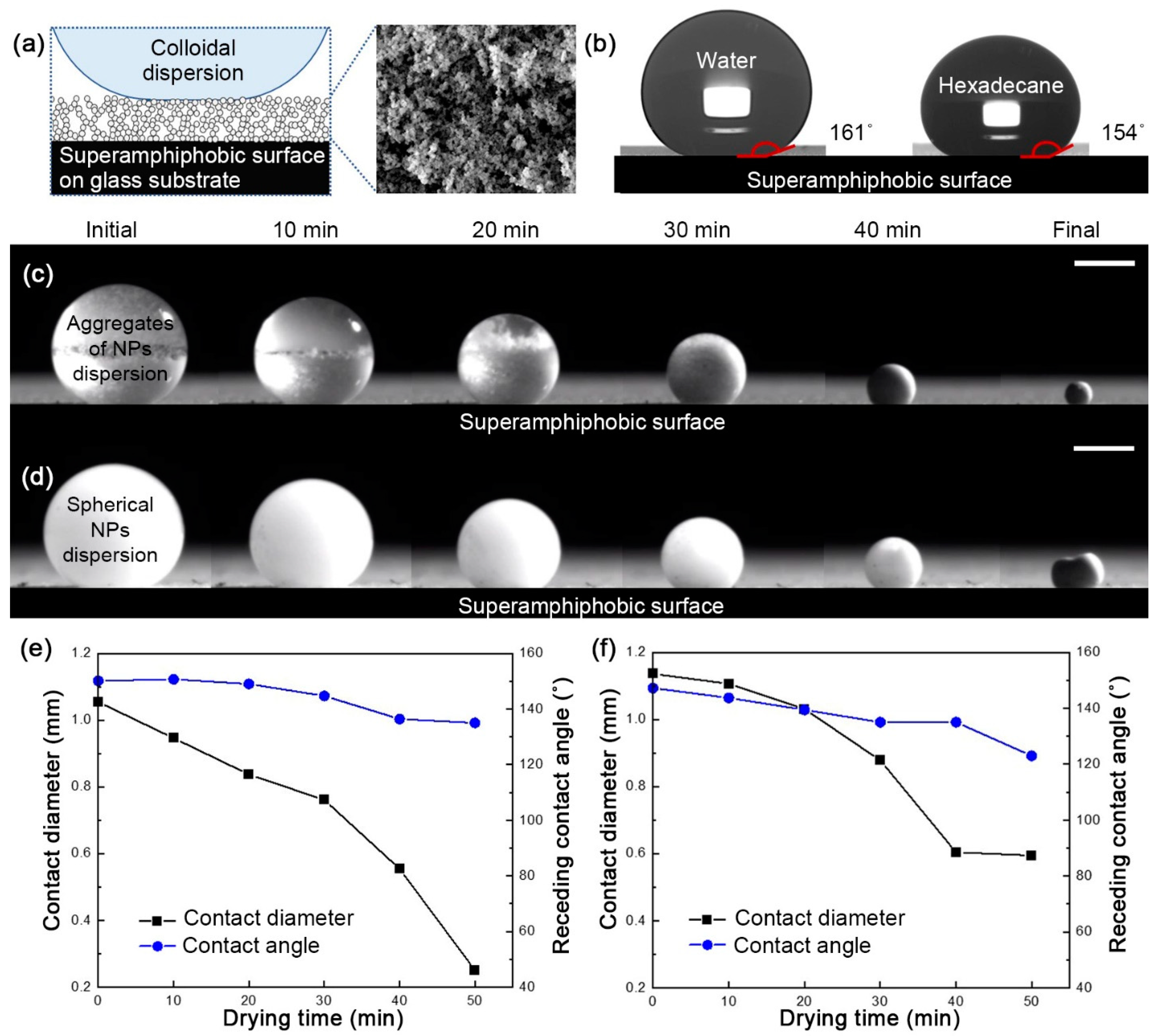
2.2. Superamphiphobic Soot Surface Fabrication

To fabricate superamphiphobic soot surface [19], the candle flame was settled under the slide glass for soot layer deposition. The glass should be held on the flame for approximately 5 min to turn black. Chemical vapor deposition (CVD) of 600 μL of tetraethyl orthosilicate (TEOS) and aqueous ammonia solution in a desiccator was held on for 24 h, leading to a coating of silica shell on the soot layer. The ammonia solution acts as a catalyst, thus leads to hydrolysis and condensation of TEOS. Calcination of the carbon and silica layer at 500 °C for 2 h results in combustion of the carbon layer. For surface energy reduction, CVD of 50 μL of trichloro (1H, 1H, 2H, 2H-perfluorooctyl)silane was held on a vacuum-applied desiccator for 1 h.

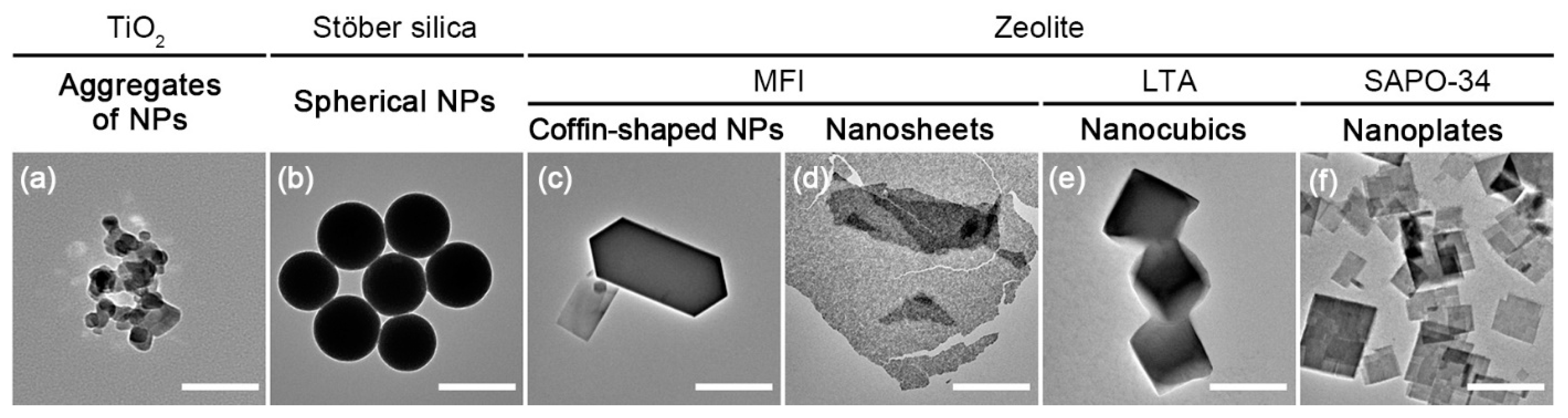
2.3. Particle Fabrication

Various morphologies of aluminosilicate crystals and silica were prepared through hydrothermal methods. Zeolite nanoplates (SAPO-34) seed crystals were synthesized under a molar gel composition of 0.6 SiO2: 1.0 Al2O3: 4.0 TEAOH: 2.0 P2O5: 75 H2O. Crystallization was carried out at 180 °C for 48 h in a convection oven [26]. For crystallization of zeolite nanocubics (LTA), a synthesis molar composition of 6.1 SiO2: 1.0 Al2O3: 13.7 TMAOH: 0.9 NaOH: 345 H2O was utilized [27]. Crystallization was carried out at 130 °C for 24 h in a convection oven. Morphology of zeolite nanosheets (MFI) was synthesized based on the seeded growth with dC-5 (bis-1,5(tripropyl ammonium) pentamethylene diiodide) as SDAs (structure directing agents). The precursor sol molar composition was 80 TEOS: 3.8 dC-5: 20 KOH: 9500 H2O where dC-5 chemical was synthesized following recipes in the literature [28]. It was crystallized at 140 °C for 24 h. Coffined-shaped MFI crystals were prepared with a molar composition of 20 SiO2: 4.5 TPAOH: 4050 H2O. Crystallization was carried out at 150 °C for 24 h [29]. Spherical silica NPs were prepared in a molar composition of 1.0 TEOS: 11.8 ammonia: 50 H2O: 52.3 ethanol [30]. After the mixing ingredients, it was aged at 25 °C for 10 min to yield spherical silica. All prepared samples were cleaned by repeated centrifugation and decantation, and then they are redispersed in DI water.

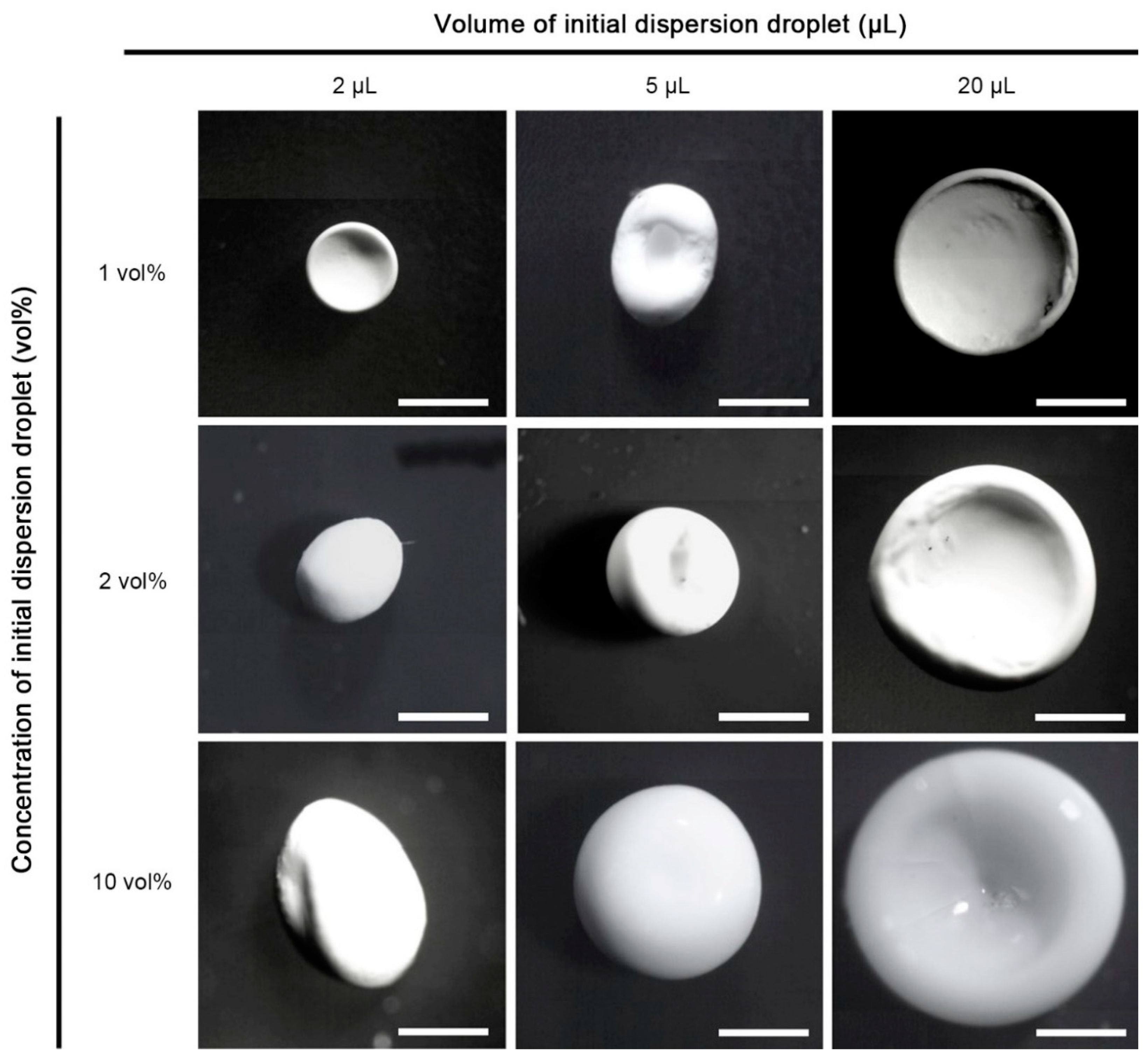
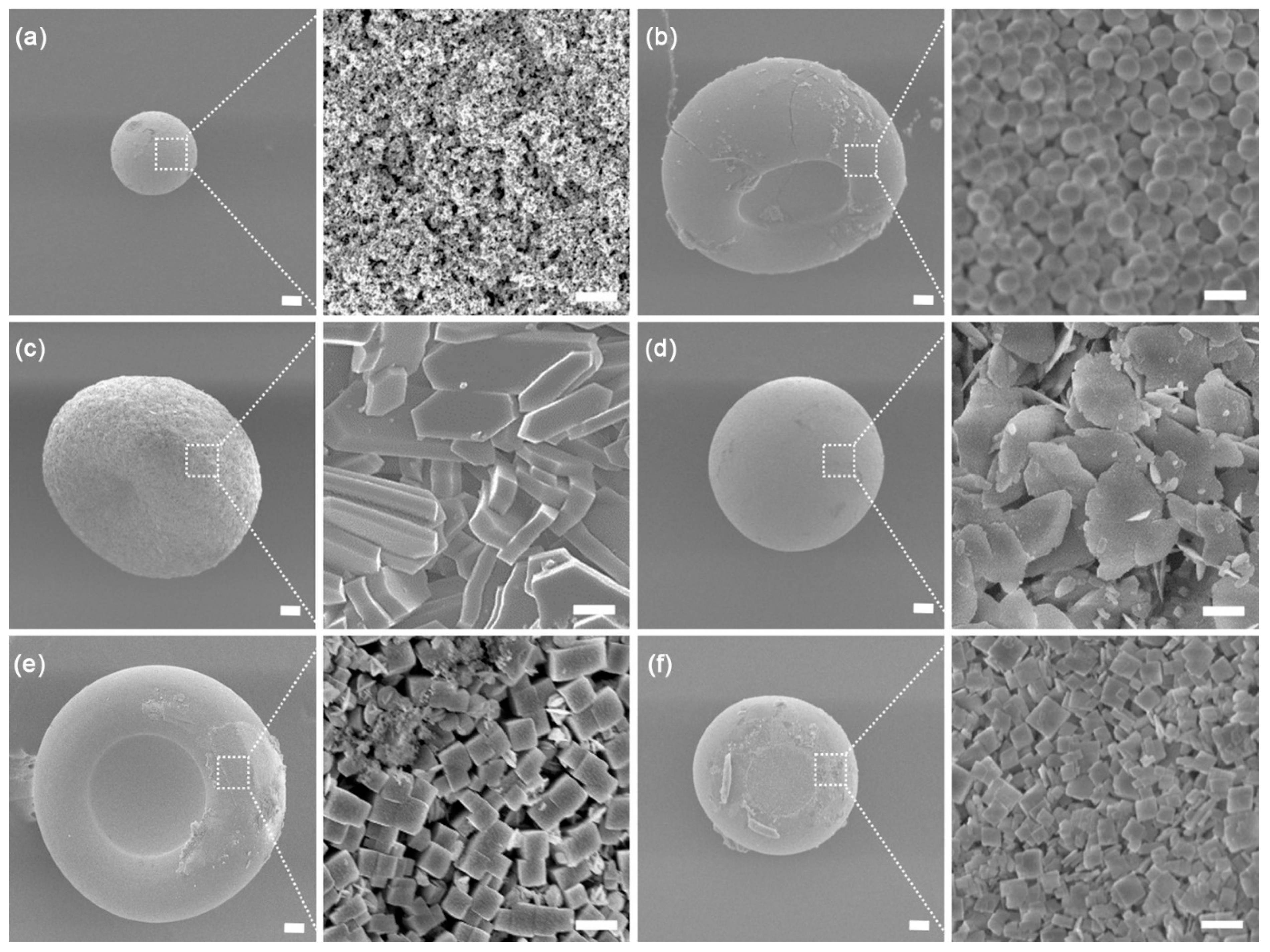
2.4. Supraparticle fabrication

Every single supraparticle was dried on a superamphiphobic surface in a humidity chamber (relative humidity 30%, temperature 25 °C).

3. Results and Discussion

For the STED supraparticle fabrication, different shapes and sizes of primary colloidal particles were prepared: (1) aggregates of TiO2 NPs, (2) spherical silica NPs, (3) coffin-shaped zeolite NPs, (4) zeolite nanosheets, (5) zeolite nanocubics, (6) zeolite nanoplates (transmission electron microscopy (TEM) images in Figure 1). The aggregates of NPs dispersion were prepared by sonication of TiO2 NPs (P25, Aeroxide, size: 20~30 nm) in water. The size and shape of the aggregates are arbitrary in the range of micron scale. The spherical silica NPs (average size: 533 ± 10 nm) were synthesized by the Stöber method [30]. The zeolites with different shapes, coffin-shaped NPs (average size: long axis of 3.8 ± 2.2 µm, short axis of 1.3 ± 0.8 µm, and thickness of 380 ± 220 nm), nanosheets (average size: width of 2 µm and thickness of 5 nm), nanocubics (average size: 670 ± 140 nm), and nanoplates (size: thickness of 0.3 µm and lateral size of 630 ± 110 nm), were synthesized by following previous literatures [26,27,28,29,30]. After synthesis, these zeolites powders were dispersed in water as colloidal dispersions.
In order to fabricate supraparticles via the STED method, the soot-templated superamphiphobic surfaces were used as a template (Figure 2a) [19]. The highly porous soot-templated superamphiphobic surface showed high apparent contact angles for water (>160°) and hexadecane (~150°) and low sliding angles below 10° for both drops (5 µL) (Figure 2b). Due to the low frictions of liquid drops on the superamphiphobic surface, the receding contact line can freely move by evaporation. On the superamphiphobic surfaces, various supraparticles were synthesized by drying colloidal dispersion drops with different primary particles. Drying behaviors of the dispersion drops of the aggregates of NPs and the spherical NPs on superamphiphobic surfaces were characterized by side-camera during evaporation (Figure 2c,d). Both dispersion drops formed supraparticles at the end of evaporation while the shapes were slightly different. The shape of the supraparticle from the aggregates of NPs was spherical (the last picture of Figure 2c). The spherical dispersion drop symmetrically shrunk as a consequence of evaporation. The contact diameter of dispersion drop gradually decreased with almost constant receding contact angle, characterized by side-pictures (Figure 2e). This evaporation of constant contact angle mode allows spherical supraparticles at the end of evaporation. In the case of the supraparticles from the dispersion drop of spherical NPs, the doughnut-like supraparticle with a crater at the top was prepared (the last picture of Figure 2d). The crater was caused by a shell formation of colloidal particle assembly at the air/liquid interface [35]. The spherical NPs in water formed well-dispersed colloidal dispersion (Figure 2d). By evaporation, the concentration of NPs at the air/water interface increased, causing the shell with colloidal assembly. The rigid shell delayed the contact diameter shrinking, which collapsed the drop shape from the top, resulting in the supraparticle of the doughnut shape after the evaporation process (Figure 2f). The aggregates of NPs did not make the shell because most aggregates were agglomerated and sunk at the bottom of the dispersion drop by gravity (Figure 2c). Therefore, only few NPs existed at the air/water interface which were not enough to form a shell.
This difference between two primary colloidal particles fabricated different shapes as illustrated in Figure S1. The size of supraparticles could be easily tuned by using different concentrations and volumes of dispersion drops. The sizes of TiO2 supraparticles were varied from 288 ± 10 µm to 1076 ± 30 µm in diameter, which were all spherical shape (Figure 3). In contrary, most supraparticles from spherical NPs showed a collapsed top with craters due to the shell formation (Figure 4). The spherical and doughnut-like shapes of the supraparticles from the dispersion drops of the aggregates of NPs (0.2 vol %, 5 µL) and the spherical NPs (2 vol %, 5 µL) were confirmed by scanning electron microscope (SEM) images (Figure 5a,b). Both supraparticles are porous with assemblies of TiO2 NPs and spherical NPs, respectively (magnified images at the right of Figure 5a,b). The dispersion drops (0.2 vol %, 5 µL) of the coffin-shaped zeolite NPs, zeolite nanosheets, zeolite nanocubics, and zeolite nanoplates were also successfully formed supraparticles by the STED method on the superamphiphobic surfaces (Figure 5c–f). All kinds of primary colloidal particles were strongly packed by capillary force via the meniscus of the drying water among the particles, which allowed the formation of supraparticles with various colloidal assemblies after evaporation.
In addition to the single component supraparticles, multiple-components heterogeneous supraparticles were introduced by the STED method with the colloidal mixture dispersion drops. The mixture dispersion drops of the spherical NPs and nanocubics (1:1 volume ratio, 5 µL) created the supraparticles of well-mixed assembly, as in the illustration in Figure 6a. The well-mixed spherical NPs and nanocubics at the surface of the supraparticle were characterized by SEM (Figure 6b,c). Moreover, it was confirmed that inside the supraparticle, was also composed of the well-mixed structure of the spherical NPs and nanocubics, which was characterized by SEM after breaking the supraparticle (Figure 6d,e). The sizes of spherical NPs and nanocubics were similar, 533 ± 10 nm and 670 ± 140 nm, respectively. Both colloidal particles were dispersed well in water. Therefore, no concentration difference was generated at the dispersion drop during the evaporation, which resulted in the supraparticle of well-mixed spherical and cubic shaped colloidal particles.
When the dispersion drop of the colloidal particles mixture of two different sizes, the spherical NPs (size: 533 ± 10 nm) and coffin-shaped zeolite NPs (size: long axis of 3.8 ± 2.2 µm, short axis of 1.3 ± 0.8µm, and thickness of 380 ± 220 nm), were dried on the superamphiphobic surface, a core/shell supraparticle was synthesized (Figure 7a). The SEM images of the surface of the supraparticle, fabricated by drying the spherical NPs and coffin-shaped NPs mixture dispersion drop (1:1 volume ratio, 5 µL), exhibited an assembly consisting of only spherical NPs (Figure 7b,c). No coffin-shaped NPs were observed at the outer surface of the supraparticle. The coffin-shaped NPs appeared only inside of the supraparticle which were characterized by SEM after breaking the supraparticle (Figure 7d–f). The compositions at the core and the shell were separated with a clear boundary of the coffin-shaped NPs and the spherical NPs. This core/shell structure formation agreed well with the previous literature about the size effect on primary colloidal particles [31]. It was studied that the dispersion drop of the spherical colloidal mixture of the two different sizes prepared core/shell structured supraparticles by the STED method. By the evaporation of water, a chemical potential gradient, relating to the local concentration of colloidal particles, is generated from the outer surface to the center of the dispersion drop. Because bigger particles, taking larger volume, lead to a larger chemical potential gradient than smaller particles, the bigger particles are pushed more away from the air/liquid interface of the drop by a stronger driving force than the smaller particles, causing the core/shell morphology. Here, we found that the colloid size effect was still dominant for morphology of the supraparticles even for the primary colloidal particles of different shapes. Indeed, the shape of primary colloidal particles does not influence the morphology of the supraparticle fabricated by the STED method.
The dispersion drop of the mixture with spherical NPs and TiO2 aggregates of NPs (1:1 volume ratio, 5 µL) also formed the supraparticle of the core/shell morphology, however, in this case, the TiO2 NPs of 20~30 nm and the silica NPs of 533 ± 10 nm occupied the core and the shell, respectively, which was opposite the core/shell morphology with the supraparticle of the spherical NPs and coffin-shaped NPs (Figure 8a). We observed that the outer region of the supraparticle was predominantly occupied by the spherical particles (Figure 8b,c). In contrary, at the center and bottom of the supraparticle, the volume was occupied by the TiO2 NPs more than the spherical NPs (Figure 8d–e). It happened because the TiO2 assembly was formed from the aggregates of NPs. Most aggregates of NPs were precipitated at the bottom of the dispersion drop during the evaporation. Therefore, the TiO2 concentration at the surface of the supraparticle was much lower than at the center and bottom of the supraparticle. At the end of evaporation, the precipitated aggregates of NPs at the bottom of the drop occupied the core dominantly and most well-dispersed spherical NPs formed the shell of the supraparticle even though the size of TiO2 NPs is smaller than silica NPs. This strategy, using the mixture of well-dispersed colloids and aggregates of colloids, introduces a new way to fabricate an inverse core/shell morphology (core with small particles/shell with big particles) of the supraparticle by one-pot drying.
Even more complex morphology, a Janus core/shell structure of supraparticles could be synthesized by the STED method with three different primary colloidal particles (Figure 8a). The combination of the well-dispersed colloidal particles of two different sizes (the coffin-shaped zeolite and the spherical NPs) and the aggregates of TiO2 NPs (0.5:0.5:2 volume ratio, 5 µL) were used for synthesizing the Janus core/shell structure. Not only NP distribution but also many factors affect the formation of the supraparticle with the crater or rigid shell. For ease of analysis, 0.5:0.5:2 volume ratio was chosen because it forms the spherical supraparticle. In Figure 7 and Figure 8, both the dispersion drops of (1) the mixture of the spherical NPs and the coffin-shaped zeolite NPs and (2) the mixture of the spherical NPs and TiO2 aggregates of NPs formed supraparticles of a core/shell morphology. Particularly, the aggregates of NPs made a core by the precipitation of aggregates at the bottom of the dispersion drop. In addition, the shells of both supraparticles were occupied by the spherical NPs. Therefore, the dispersion drop of the three primary colloidal particles formed the shell with spherical NPs and the core with coffin-shaped NPs and TiO2 NPs. The morphologies of the outer and center of the supraparticles were confirmed by SEM (Figure 9b–f) with energy dispersive spectroscopy (EDS, Figure S2). The core was divided with two regions. Because the aggregates of NPs tended to be precipitated, the bottom-side and the top-side cores were occupied by TiO2 NPs and the coffin-shaped NPs, respectively, so that it was called the Janus core. The combination effect of (i) size difference of well-dispersed particles and (ii) aggregates of particles, allowed to produce a novel Janus core/shell morphology of supraparticles.

4. Conclusions

By the STED method, dispersion drops of varied primary colloidal particles produce supraparticles with different morphologies. Our current work introduces supraparticle fabrication from six primary colloidal particles of different size, shape, and dispersity, and their mixtures. It is newly found that the shape and size of the primary colloidal particle rarely influence the morphology of the single component supraparticle. For the multi-component supraparticles, the size and the dispersity of colloids affect the morphology, while there is no effect on the shape of primary colloidal particles. For the two or three components mixture system, (i) well-mixed, (ii) core/shell, and (iii) Janus core/shell can be synthesized by the STED method. By combining the effects of colloid size and the aggregate on the morphology of the supraparticle, the above three different morphologies can be fabricated by simple one-pot drying. This study can provide important information to manufacture different structured supraparticles such as the inverse opal structured supraparticle. In addition, we anticipate that the supraparticles with various morphologies will further widen the application and research fields of the STED method.

Supplementary Materials

The following are available online at https://www.mdpi.com/2073-4352/11/2/79/s1, Figure S1: Particle flow behavior during evaporation-driven surface templated synthesis; Figure S2: Energy dispersive spectroscopy data of Janus core/shell supraparticle.

Author Contributions

Conceptualization, validation, W.S., S.W.; Investigation, W.S.; Methodology, W.S., C.S.M., H.K.; Resources, H.S.K., H.Z., S.K.K.; Writing—original draft preparation, W.S., C.S.M., S.W.; Writing—review and editing, S.W.; Supervision, P.S.L., S.W. All authors have read and agreed to the published version of the manuscript.

Funding

This research was supported by the Chung-Ang University Research Scholarship Grants in 2019 and the grant(19CTAP-C151876-01) from Technology Advancement Research Program (TARP) funded by Ministry of Land, Infrastructure and Transport of Korean government.

Data Availability Statement

The data presented in this study are available in article and supplementary material.

Conflicts of Interest

The authors declare no conflict of interest.

References

  1. Wintzheimer, S.; Granath, T.; Oppmann, M.; Kister, T.; Thai, T.; Kraus, T.; Vogel, N.; Mandel, K. Supraparticles: Functionality from Uniform Structural Motifs. ACS Nano 2018, 12, 5093–5120. [Google Scholar] [CrossRef] [PubMed]
  2. Schlögl, R.; Abd Hamid, S.B. Nanocatalysis: Mature science revisited or something really new? Angew. Chem. Int. Ed. 2004, 43, 1628–1637. [Google Scholar] [CrossRef] [PubMed]
  3. Li, S.; Liu, J.; Ramesar, N.S.; Heinz, H.; Xu, L.; Xu, C.; Kotov, N.A. Single-and multi-component chiral supraparticles as modular enantioselective catalysts. Nat. Commun. 2019, 10, 1–10. [Google Scholar] [CrossRef] [PubMed] [Green Version]
  4. Gu, M.; Lee, W.-r.; Kim, M.; Kang, J.; Lee, J.S.; Thompson, L.T.; Kim, B.-S. Structure-tunable supraparticle assemblies of hollow cupric oxide sheathed with nanographenes. Nanoscale Adv. 2020, 2, 1236–1244. [Google Scholar] [CrossRef]
  5. Huang, J.; Xiao, Y.; Peng, Z.; Xu, Y.; Li, L.; Tan, L.; Yuan, K.; Chen, Y. Co3O4 supraparticle-based bubble nanofiber and bubble nanosheet with remarkable electrochemical performance. Adv. Sci. 2019, 6, 1900107. [Google Scholar] [CrossRef] [Green Version]
  6. Ma, Y.; Björnmalm, M.; Wise, A.K.; Cortez-Jugo, C.; Revalor, E.; Ju, Y.; Feeney, O.M.; Richardson, R.T.; Hanssen, E.; Shepherd, R.K. Gel-mediated electrospray assembly of silica supraparticles for sustained drug delivery. ACS Appl. Mater. Interfaces 2018, 10, 31019–31031. [Google Scholar] [CrossRef]
  7. Ulrich, S.; Hirsch, C.; Diener, L.; Wick, P.; Rossi, R.M.; Bannwarth, M.B.; Boesel, L.F. Preparation of ellipsoid-shaped supraparticles with modular compositions and investigation of shape-dependent cell-uptake. RSC Adv. 2016, 6, 89028–89039. [Google Scholar] [CrossRef]
  8. Zhou, H.; Kim, J.P.; Bahng, J.H.; Kotov, N.A.; Lee, J. Self-Assembly Mechanism of Spiky Magnetoplasmonic Supraparticles. Adv. Funct. Mater. 2014, 24, 1439–1448. [Google Scholar] [CrossRef] [Green Version]
  9. Maas, M.; Silvério, C.C.; Laube, J.; Rezwan, K. Electrostatic assembly of zwitterionic and amphiphilic supraparticles. J. Colloid Interface Sci. 2017, 501, 256–266. [Google Scholar] [CrossRef]
  10. Egly, S.; Fröhlich, C.; Vogel, S.; Gruenewald, A.; Wang, J.; Detsch, R.; Boccaccini, A.R.; Vogel, N. Bottom-Up Assembly of Silica and Bioactive Glass Supraparticles with Tunable Hierarchical Porosity. Langmuir 2018, 34, 2063–2072. [Google Scholar] [CrossRef]
  11. Wang, W.-N.; Lenggoro, I.W.; Okuyama, K. Dispersion and aggregation of nanoparticles derived from colloidal droplets under low-pressure conditions. J. Colloid Interface Sci. 2005, 288, 423–431. [Google Scholar] [CrossRef] [PubMed]
  12. Paudel, A.; Worku, Z.A.; Meeus, J.; Guns, S.; Van den Mooter, G. Manufacturing of solid dispersions of poorly water soluble drugs by spray drying: Formulation and process considerations. Int. J. Pharm. 2013, 453, 253–284. [Google Scholar] [CrossRef] [PubMed]
  13. Lintingre, E.; Lequeux, F.; Talini, L.; Tsapis, N. Control of particle morphology in the spray drying of colloidal suspensions. Soft Matter 2016, 12, 7435–7444. [Google Scholar] [CrossRef] [Green Version]
  14. Wooh, S.; Huesmann, H.; Tahir, M.N.; Paven, M.; Wichmann, K.; Vollmer, D.; Tremel, W.; Papadopoulos, P.; Butt, H.-J. Synthesis of Mesoporous Supraparticles on Superamphiphobic Surfaces. Adv. Mater. 2015, 27, 7338–7343. [Google Scholar] [CrossRef] [PubMed]
  15. Wooh, S.; Butt, H.-J. A Photocatalytically Active Lubricant-Impregnated Surface. Angew. Chem. Int. Ed. 2017, 56, 4965–4969. [Google Scholar] [CrossRef]
  16. Wang, L.; McCarthy, T.J. Covalently Attached Liquids: Instant Omniphobic Surfaces with Unprecedented Repellency. Angew. Chem. Int. Ed. 2016, 55, 244–248. [Google Scholar] [CrossRef]
  17. Chen, L.; Hong, J.; Butt, H.-J.; Wooh, S. Liquid-Repellent Metal Oxide Photocatalysts. Chem. A Eur. J. 2019, 25, 4535–4542. [Google Scholar] [CrossRef]
  18. Chen, L.; Park, S.; Yoo, J.; Hwang, H.; Kim, H.; Lee, J.; Hong, J.; Wooh, S. One-Step Fabrication of Universal Slippery Lubricated Surfaces. Adv. Mater. Interfaces 2020, 7, 2000305. [Google Scholar] [CrossRef]
  19. Deng, X.; Mammen, L.; Butt, H.-J.; Vollmer, D. Candle Soot as a Template for a Transparent Robust Superamphiphobic Coating. Science 2012, 335, 67. [Google Scholar] [CrossRef]
  20. Sekido, T.; Wooh, S.; Fuchs, R.; Kappl, M.; Nakamura, Y.; Butt, H.-J.; Fujii, S. Controlling the Structure of Supraballs by pH-Responsive Particle Assembly. Langmuir 2017, 33, 1995–2002. [Google Scholar] [CrossRef]
  21. Tan, H.; Wooh, S.; Butt, H.-J.; Zhang, X.; Lohse, D. Porous supraparticle assembly through self-lubricating evaporating colloidal ouzo drops. Nat. Commun. 2019, 10, 478. [Google Scholar] [CrossRef] [PubMed]
  22. Liu, W.; Kappl, M.; Butt, H.-J. Tuning the Porosity of Supraparticles. ACS Nano 2019, 13, 13949–13956. [Google Scholar] [CrossRef] [PubMed] [Green Version]
  23. Xia, Y.; Nguyen, T.D.; Yang, M.; Lee, B.; Santos, A.; Podsiadlo, P.; Tang, Z.; Glotzer, S.C.; Kotov, N.A. Self-assembly of self-limiting monodisperse supraparticles from polydisperse nanoparticles. Nat. Nanotechnol. 2011, 6, 580–587. [Google Scholar] [CrossRef] [PubMed]
  24. Sperling, M.; Velev, O.D.; Gradzielski, M. Controlling the Shape of Evaporating Droplets by Ionic Strength: Formation of Highly Anisometric Silica Supraparticles. Angew. Chem. Int. Ed. 2014, 53, 586–590. [Google Scholar] [CrossRef] [PubMed]
  25. Hu, M.; Butt, H.-J.; Landfester, K.; Bannwarth, M.B.; Wooh, S.; Thérien-Aubin, H. Shaping the Assembly of Superparamagnetic Nanoparticles. ACS Nano 2019, 13, 3015–3022. [Google Scholar] [CrossRef] [PubMed] [Green Version]
  26. Huang, Y.; Wang, L.; Song, Z.; Li, S.; Yu, M. Growth of high-quality, thickness-reduced zeolite membranes towards N2/CH4 separation using high-aspect-ratio seeds. Angew. Chem. 2015, 127, 10993–10997. [Google Scholar] [CrossRef]
  27. Yu, S.; Kwon, S.; Na, K. Synthesis of LTA zeolites with controlled crystal sizes by variation of synthetic parameters: Effect of Na+ concentration, aging time, and hydrothermal conditions. J. Sol Gel Sci. Technol. 2018, 1–11. [Google Scholar] [CrossRef]
  28. Jeon, M.Y.; Kim, D.; Kumar, P.; Lee, P.S.; Rangnekar, N.; Bai, P.; Shete, M.; Elyassi, B.; Lee, H.S.; Narasimharao, K. Ultra-selective high-flux membranes from directly synthesized zeolite nanosheets. Nature 2017, 543, 690–694. [Google Scholar] [CrossRef]
  29. Pham, T.C.T.; Kim, H.S.; Yoon, K.B. Growth of uniformly oriented silica MFI and BEA zeolite films on substrates. Science 2011, 334, 1533–1538. [Google Scholar] [CrossRef]
  30. Ibrahim, I.A.; Zikry, A.; Sharaf, M.A. Preparation of spherical silica nanoparticles: Stober silica. J. Am. Sci. 2010, 6, 985–989. [Google Scholar]
  31. Liu, W.; Midya, J.; Kappl, M.; Butt, H.-J.; Nikoubashman, A. Segregation in Drying Binary Colloidal Droplets. ACS Nano 2019, 13, 4972–4979. [Google Scholar] [CrossRef] [PubMed]
  32. Lotito, V.; Zambelli, T. Pattern detection in colloidal assembly: A mosaic of analysis techniques. Adv. Colloid Interface Sci. 2020, 284, 102252. [Google Scholar] [CrossRef] [PubMed]
  33. Lotito, V.; Zambelli, T. Pattern Formation in Binary Colloidal Assemblies: Hidden Symmetries in a Kaleidoscope of Structures. Langmuir 2018, 34, 7827–7843. [Google Scholar] [CrossRef] [PubMed]
  34. Lotito, V.; Zambelli, T. A Journey Through the Landscapes of Small Particles in Binary Colloidal Assemblies: Unveiling Structural Transitions from Isolated Particles to Clusters upon Variation in Composition. Nanomaterials 2019, 9, 921. [Google Scholar] [CrossRef] [PubMed] [Green Version]
  35. Rastogi, V.; García, A.A.; Marquez, M.; Velev, O.D. Anisotropic Particle Synthesis Inside Droplet Templates on Superhydrophobic Surfaces. Macromol. Rapid Commun. 2010, 31, 190–195. [Google Scholar] [CrossRef]
Figure 1. TEM images of various shapes of nanoparticles (NPs). (a) Aggregates of NPs, (b) spherical NPs, and (c) coffin-shaped NPs, (d) nanosheets, (e) nanocubics, and (f) nanoplates. The scales are 100 nm for (a), 500 nm for (b), and 1 μm for (cf).
Crystals 11 00079 g001
Figure 2. Supraparticle synthesis by evaporation-driven surface templated synthesis. (a) Structure of the soot-templated superamphiphobic surface characterized by SEM (left), and a schematic of the colloidal dispersion drop on the superamphiphobic surface with high static contact angle. (b) Static contact angles of water and hexadecane drops on the superamphiphobic surface. Time snapshots of drying colloidal aqueous dispersion of (c) aggregates of NPs (concentration: 0.2 vol %) and (d) spherical NPs (concentration: 2 vol %) drop on the superamphiphobic surface. (e) Contact angle and contact diameter of TiO2 supraparticle over drying times given in (c). (f) Contact angle and contact diameter of the silica supraparticle over drying times given in (d). The scale bars are 1 μm for (a) and 1 mm for (c,d).
Crystals 11 00079 g002
Figure 3. Optical microscopic images of various sizes of TiO2 supraparticles from different aggregates of NP concentrations (0.1, 0.2, 1 vol %) and volume (2, 5, 20 µL) of initial dispersion drops. The scale bars are 500 μm.
Crystals 11 00079 g003
Figure 4. Optical microscopic images of various sizes of silica supraparticles from different spherical NP concentrations (1, 2, 10 vol %) and volume (2, 5, 20 µL) of initial dispersion drops. The scale bars are 500 μm.
Crystals 11 00079 g004
Figure 5. SEM images of supraparticles. Supraparticles fabricated by (a) aggregates of NPs, (b) spherical NPs, and (c) coffin-shaped NPs, (d) nanosheets, (e) nanocubics, (f) nanoplates. The scale bars are 100 μm for the left image and 1 μm for the magnified images at the right of each figure.
Crystals 11 00079 g005
Figure 6. Well-mixed assembly of the supraparticle. (a) A schematic of the well-mixed supraparticle with nanocubics/spherical NPs. (b,c) SEM images of surface of the well-mixed supraparticle. (d) Cross-sectional SEM image of the well-mixed supraparticle, characterized after breaking the supraparticle. (e) High magnification SEM image of the inner-structure of the well-mixed supraparticle. The scales are 100 μm for (b,d) and 1 μm for (c,e).
Crystals 11 00079 g006
Figure 7. Core/shell supraparticle by size effect. (a) A schematic of core/shell supraparticle with coffin-shaped NPs/spherical NPs. (b,c) SEM images of the surface of the core-shell supraparticle. (e) Cross-sectional SEM image of the core-shell supraparticle, characterized after breaking the supraparticle. (d,f) High magnification SEM images of the inner-structure (indicated as boxes in image (e)) of the supraparticle; (e) the core of core and shell and (f) the boundary, respectively. The scales are 100 μm for (b,e) and 1 μm for (c,d,f).
Crystals 11 00079 g007
Figure 8. Core/shell supraparticle by dispersity effect. (a) A schematic of the bi-composite supraparticle with aggregates of NPs/spherical NPs. (b,c) SEM images of the surface of the bi-composite supraparticle. (e) Cross-sectional SEM image of the bi-composite supraparticle, characterized after breaking the supraparticle. (d,e) High magnification SEM images of the inner-structure (indicated as boxes in image (e) of the supraparticle; (d) the boundary and (e) the core of core and shell, respectively. The scales are 100 μm for (b,e) and 1 μm for (c,d).
Crystals 11 00079 g008
Figure 9. Janus core/shell structured supraparticle. (a) A schematic of the tri-composite supraparticle with aggregates of NPs/coffin-shaped NPs/spherical NPs. (b,c) SEM images of the surface of Janus core/shell supraparticle. (d) High magnification the SEM image of the inner-structure of the Janus core/shell structured supraparticle; the shell. (e) Cross-sectional SEM image of the Janus core/shell structured supraparticle, characterized after breaking the supraparticle. (f) High magnification SEM image of the inner-structure of the Janus core/shell structured supraparticle; the core. The scales are 100 μm for (b,e), 1 μm for (c,d,f).
Crystals 11 00079 g009
Publisher’s Note: MDPI stays neutral with regard to jurisdictional claims in published maps and institutional affiliations.

