1. Introduction
Laser powder bed fusion (LPBF) metal-additive manufacturing has the potential to be widely used by different industries due to its strengths in developing new alloys and producing products with more complex geometries than other traditional manufacturing techniques such as machining and casting [
1,
2]. However, it is still very challenging to effectively control the quality of the final products in LPBF. Porosity in the final products is a common issue in LPBF, which has detrimental effects on the mechanical properties of the products, although, for some special applications, a certain amount of porosity is required [
3,
4]. The generation of part porosity in LPBF is mainly induced by three process-induced defects, which include lack-of-fusion, balling, and keyholing. Lack-of-fusion is induced by the insufficient overlapping of molten pools in adjacent scan layers and tracks [
5]. A balling phenomenon can occur in both the low-energy input regime and high-energy input regime [
6]. This is related to the poor wettability of the melting tracks [
7]. Keyholing is related to the evaporation of materials, and it usually happens in the high-energy input regime [
1]. This work investigates the porosity induced by lack of fusion.
Experimental investigation, numerical modeling methods and physics-based analytical methods are three widely developed strategies for the study of additive manufacturing processes. Experimental techniques were employed to observe the melting process, generation of defects, and to measure the part quality in LPBF. Zhao et al. [
8] utilized a high-speed X-ray imaging method to study the in situ melting process of LPBF; the formation process of keyhole pores was also investigated by experimental observation. King et al. [
9] employed optical microscopy to observe the dimensions and shapes of molten pools in keyhole melting mode. Additionally, Synchrotron Radiation Micro-Tomography (SRμT) was employed by the authors to investigate the 3D voids distribution in the molten pools. Based on the experimental results, the threshold of keyholing was studied. Dilip et al. [
10] used optical micrographs to investigate the influence of process conditions on the generation of part porosity in the LPBF of Ti-6Al4V. It was found that porosity appeared under both high-energy density and low-energy density process conditions. Kasperovich et al. [
11] also employed synchrotron tomography to study the characteristics of voids distribution in products manufactured by LPBF, the sensitivity of part porosity to laser power; scan speed, hatch space and focus distance were investigated. Kamath et al. [
12] also studied the influence of process parameters on part porosity in powder bed fusion through experimental measurements. The Archimedes methods were used to measure the porosity values. The effects of powder types were also studied. Aversa et al. [
13] conducted experimental investigations to study the effects of process conditions on the microstructure and mechanical performance of the final products in additive manufacturing. The optical micrographs of the cross sections of the products were used to analyze the defects. Electron Backscatter Diffraction (EBSD) inverse pole figure (IPF) maps were utilized to study the grain morphology of the fabricated products. Although experimental measurements can provide valuable contributions to the investigation of LPBF process, the complex experimental procedure and high cost of equipment hinders the wide adoption of these techniques.
Different from experimental observations, numerical methods can avoid the high cost of equipment and can be conducted more conveniently. Thus, an increasing number of numerical models were proposed for the study of different aspects in LPBF. Vastola et al. [
14] proposed a 2D modeling method for the computation of porosity in the keyhole melting mode of LPBF. The molten pool dimensions in this method were calculated through finite element analysis. Bayat et al. [
15] employed the Finite Volume Method to develop a numerical model to simulate the formation of keyhole-induced porosity. The powder size distribution was considered in that model by using a discrete element method. The predicted characteristics of pores from that model agreed well with experimental investigations. Mukherjee et al. [
16] developed a numerical modeling method to simulate the formation of the lack-of-fusion defect in LPBF, and to calculate the lack-of-fusion porosity with the consideration of heat transfer and fluid flow. The lack-of-fusion voids were determined by the analysis of the overlapping pattern of multiple molten pools in a traverse cross section of the part. Cao et al. [
17] proposed a numerical model to simulate the pore formation in LPBF, which was based on computational fluid dynamics. The powder size distribution was also considered by a discrete method. However, numerical methods usually need plenty of computational resources, which are computationally expensive.
An alternative for the numerical study is the analytical modeling method, which has a low computational cost and acceptable predictive accuracy. Several physics-based analytical models were developed to predict temperature profiles, molten pool dimensions, and common process-induced defects in LPBF. Ning et al. [
18], Tang et al. [
4], Promoppatum et al. [
19], and Elham et al. [
20] employed the Rosenthal equation to calculate the temperature profiles in LPBF and determined the molten pool geometric characteristics based on the temperature profiles. However, the effects of powder bed characteristics on the material properties were not considered in these studies. Wang et al. [
6] developed an analytical equation to compute the upper surface roughness for the parts manufactured by LPBF, with the experimentally measured molten pool dimensions as inputs. Tang et al. [
5] proposed an analytical strategy to calculate the lack-of-fusion porosity in LPBF, by analyzing the overlapping pattern of the adjacent molten pools in a transverse cross-sectional area of a part. However, the un-overlapping portion was considered to be purely empty in the simulation process. The existence of un-melted powders in the un-overlapping portion was not considered. In other words, the effects of powder bed void fraction were not considered in the calculation process of lack-of-fusion porosity. To consider the un-melted powders in the final products, Wang et al. [
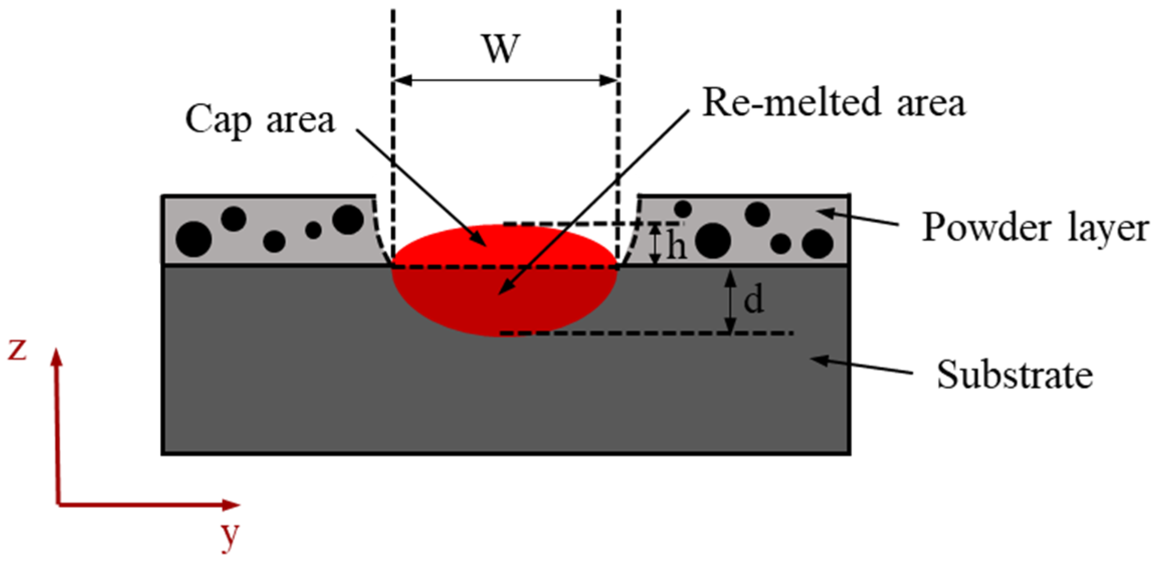
21] employed an advancing front method to simulate the packing pattern in the powder bed and compute the powder bed void fraction. A strategy, such as Tang’s method, was then utilized to calculate the lack-of-fusion area fraction (un-overlapping portion in a part). The final lack-of-fusion porosity was the product of the lack-of-fusion area fraction and powder bed void fraction. However, in that study, only the re-melted portion of the molten pool transverse cross section was considered in the modeling process. The existence of the cap area was not considered. The cap area is made of the newly melted powder layer. With the consideration of cap area, the predicted solidified molten pool cross-sectional geometries were closer to experimental observations of LPBF. Thus, the predictions of lack-of-fusion porosity were more accurate.
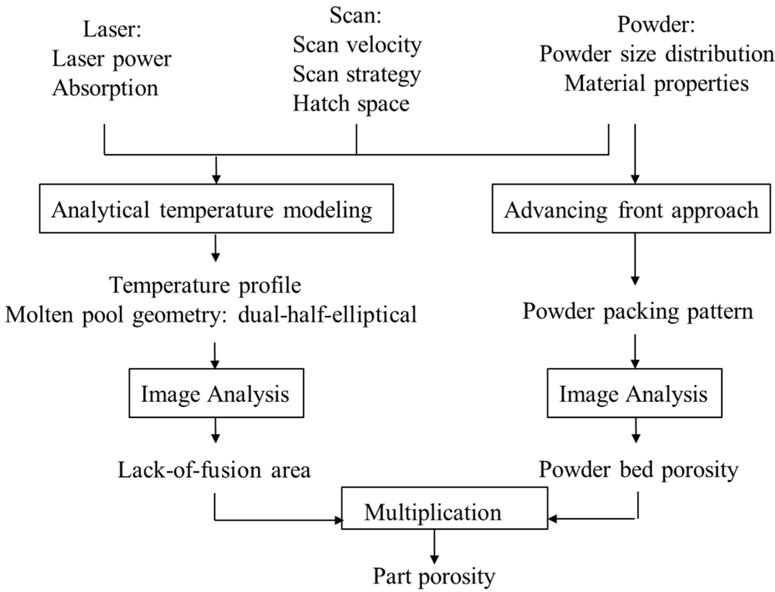
In this paper, a physics-based analytical modeling approach was presented to correlate the lack-of-fusion porosity in LPBF directly with process conditions, characteristics of the powder bed, and material properties, without relying on any iteration-based numerical calculations. Compared to previous studies, the proposed approach considers the existence of cap portion in the solidified molten pool, the influence of powder bed void fraction on material properties (i.e., powder bed material properties), and the existence of un-melted powders in the un-overlapping portion of adjacent molten pools. The consideration of cap portion and powder bed material properties causes the prediction of solidified molten pool geometries to be closer to experimental observations, which leads to a better estimation of the overlapping pattern of adjacent molten pools. Additionally, the consideration of un-melted powders increases the predictive accuracy of the lack-of-fusion porosity. The modeling process includes the following steps. An advancing front method was utilized to compute the powder bed void fraction based on the information of powder size distribution achieved through the image analysis of the SEM photo of the powder bed. The powder bed material properties were then obtained by analytical models with solid material properties and powder bed void fraction as inputs. The cross sections of molten pools were assumed to be dual half-elliptical. A steady-state point moving a heat source solution was utilized to calculate the molten pool width and re-melted depth, with the powder bed properties and process conditions as inputs. Based on the shape assumption and predicted width and re-melted depth, the size of molten pool cross section with cap area was then determined. The overlapping pattern of molten pools was achieved by plotting molten pool cross sections of multiple scan tracks and layers on a transverse cross section of the part. The lack-of-fusion area fraction (fraction of un-overlapping portion) was obtained through image analysis of the achieved overlapping pattern. The lack-of-fusion porosity was determined as the product of powder bed void fraction and lack-of-fusion area fraction. During the simulation process, the ratio between cap height to re-melted depth was determined by regression analysis. The predicted lack-of-fusion porosity under various process conditions was validated against experimental data of 316L stainless steel and predictions without cap area.
2. Analytical Modeling
In this study, an analytical strategy was proposed for the fast and accurate prediction of lack-of-fusion porosity in LPBF, with the process conditions, laser absorptivity, powder bed characteristics, and material properties as inputs.
Figure 1 shows the algorithm of the proposed analytical modeling strategy. The powder bed void fraction was obtained by an advancing front method and image analysis. The powder bed material properties were computed by analytical models, with powder bed void fraction and solid material properties as inputs. The molten pool dimensions were obtained by a physics-based thermal model. The transverse cross-sectional shape of molten pools is assumed to be a dual half-ellipse, as shown in
Figure 2, which approximates the most observed molten pool cross sections in experiments of LPBF. The cap area represents the solidified molten pool above the previous layer (or substrate), which is made of the newly melted powder layer. Due to the powder bed void fraction and the effects of surface tension, the newly melted powder layer shrinks into a shape similar to a half-ellipse after solidification. Based on this assumption and the obtained molten pool width and re-melted depth, the specific geometry of the solidified molten pool cross sections was determined. Through image analysis of the overlapping of molten pools in multiple tracks and layers, the lack-of-fusion area fraction was obtained. The lack-of-fusion porosity is the multiplication of lack-of-fusion area fraction and powder bed void fraction. The proposed analytical modeling method relies on several assumptions without sacrificing too much accuracy. First, a moving point heat source model was employed to simulate the laser power source. Second, this work only considers the lack-of-fusion defect, the balling and keyholing defects were not taken into account. Third, to calculate the powder bed void fraction using advancing front approach, the powders were assumed to be perfect spheres [
22].
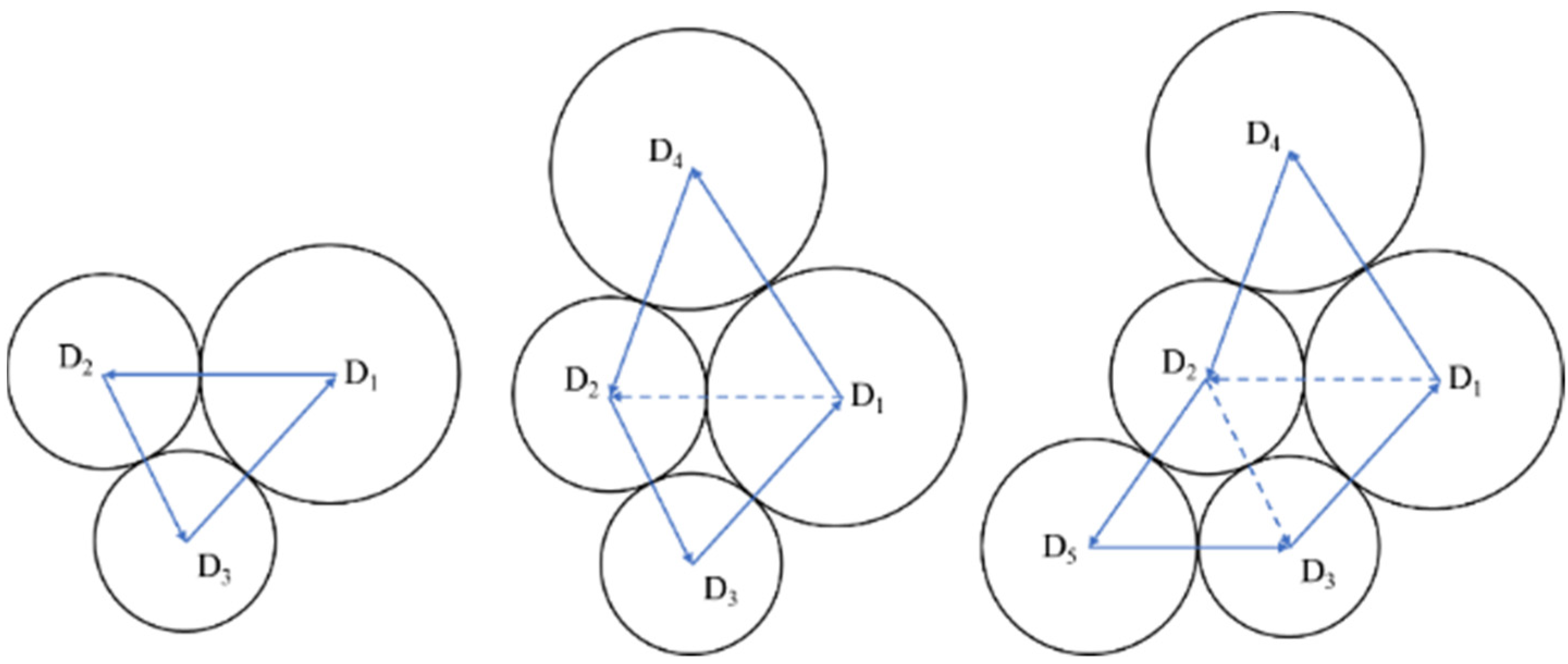
An advancing front method presented by Feng et al. [
22] was utilized to simulate the 2D packing pattern in powder bed based on the information of powder size distribution. The idea of the advancing front method is shown in
Figure 3. First, three circles are generated in the densest packing style in a plane. Then, additional circles are generated around the initial circles along the right-hand side of the vectors, as shown in
Figure 3 [
22]. The two-dimensional random packing pattern in the powder bed can be obtained through this approach, with the powder size distribution as an input. After obtaining the packing pattern, the powder bed void fraction was determined through image analysis of the 2D packing pattern.
With the information of powder bed void fraction and solid material properties, the powder bed material properties were obtained by the analytical models proposed in the literature [
23,
24], which could be expressed as:
In these equations,
,
and
represent the density, thermal conductivity, and heat capacity of powder bed, respectively. The values
, ,
denote the density, thermal conductivity, and heat capacity of solid material, respectively;
,
represent the density and thermal conductivity of gas, respectively; ε represents the powder bed void fraction; and φ is an empirical factor.
A point-moving heat source solution presented by Carslaw and Jaeger et al. in [
25] was employed as the predictive model to calculate the temperature profile in the part. It was developed based on several assumptions including semi-infinite medium, temperature-dependent material properties and steady state. The analytical expression of this heat solution is:
In this equation,
is the dimensionless temperature.
and
represent the initial temperature and melting temperature, respectively. x, y, z denote the scanning direction, transverse direction and build direction in LPBF, respectively; P, V represent the laser power and scanning speed, respectively; and η denotes the coefficient of laser absorption. The equation
denotes the distance to the laser power location, and
is the thermal diffusivity, which can be calculated based on the information of thermal conductivity K, specific heat capacity c and density
.
After obtaining the temperature profile, the molten pool width and re-melted depth were determined by comparing the temperature distribution with the melting temperature. It should be noted that the above thermal solution was validated to be accurate for the predictions of molten pool width and re-melted depth in LPBF [
5,
18,
19]. The cap height was obtained from the values of molten pool depth. The ratio between cap height and molten pool depth was determined by regression analysis. With the shape assumption and values for width, re-melted depth and cap height, the molten pool geometry was determined. After generating the overlapping pattern of the molten pools on a transverse cross-sectional area of the part, the lack-of-fusion area fraction was estimated by image analysis. The lack-of-fusion porosity of the part was computed through the following equation:
3. Experimental Validation and Discussion
This study proposed a physics-based analytical modeling method to predict the lack-of-fusion-induced porosity in LPBF. The cap area of molten pools and effects of powder bed characteristics on material properties were considered in the prediction process. To validate the proposed method, the predictions of lack-of-fusion porosity under various combinations of process conditions were compared with experimental results of 316L stainless steel from the literature [
6].
Table 1 shows the process conditions for different cases, including laser power, scanning speed, layer thickness and hatch space. The scanning strategy for this study is uni-directional.
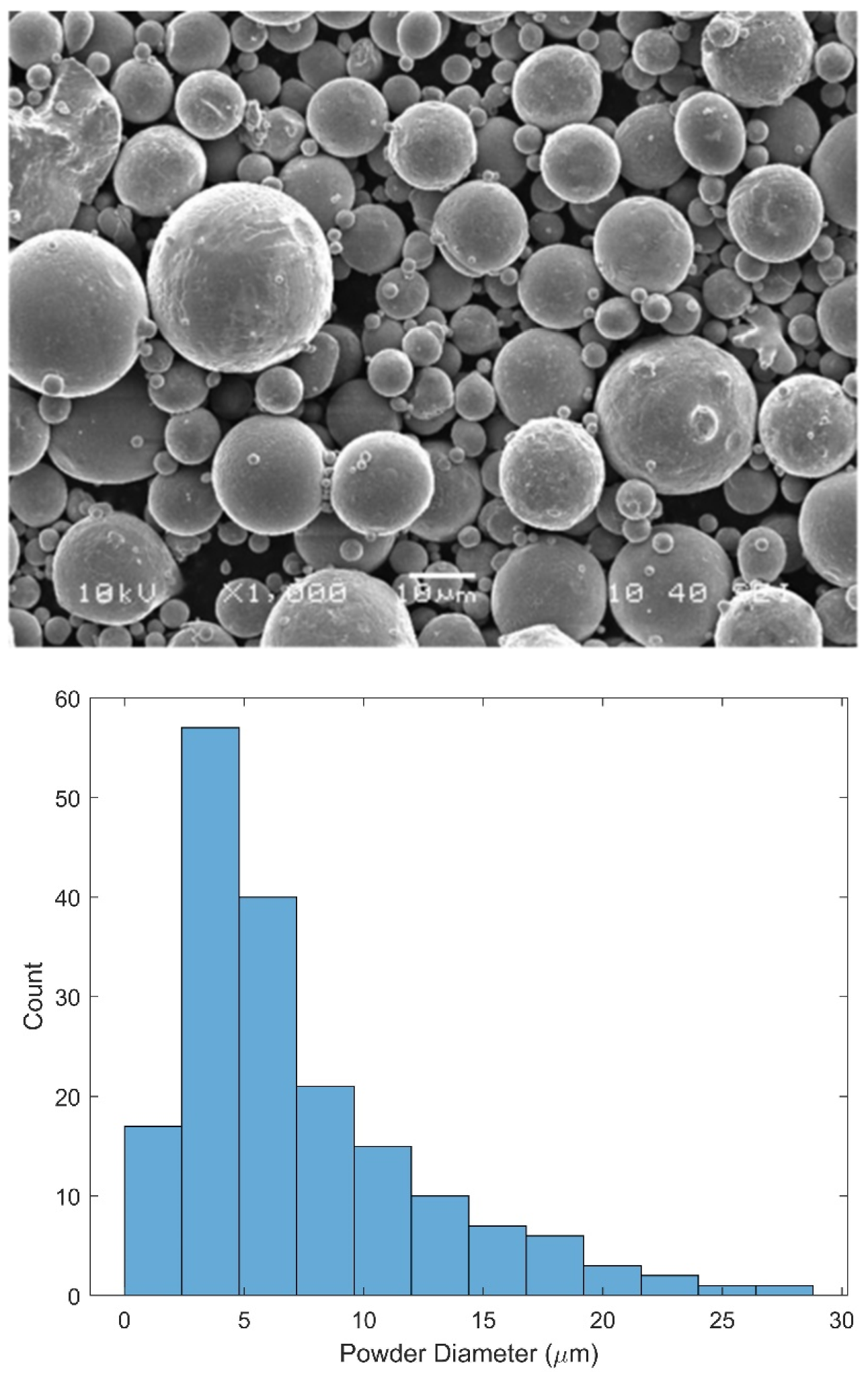
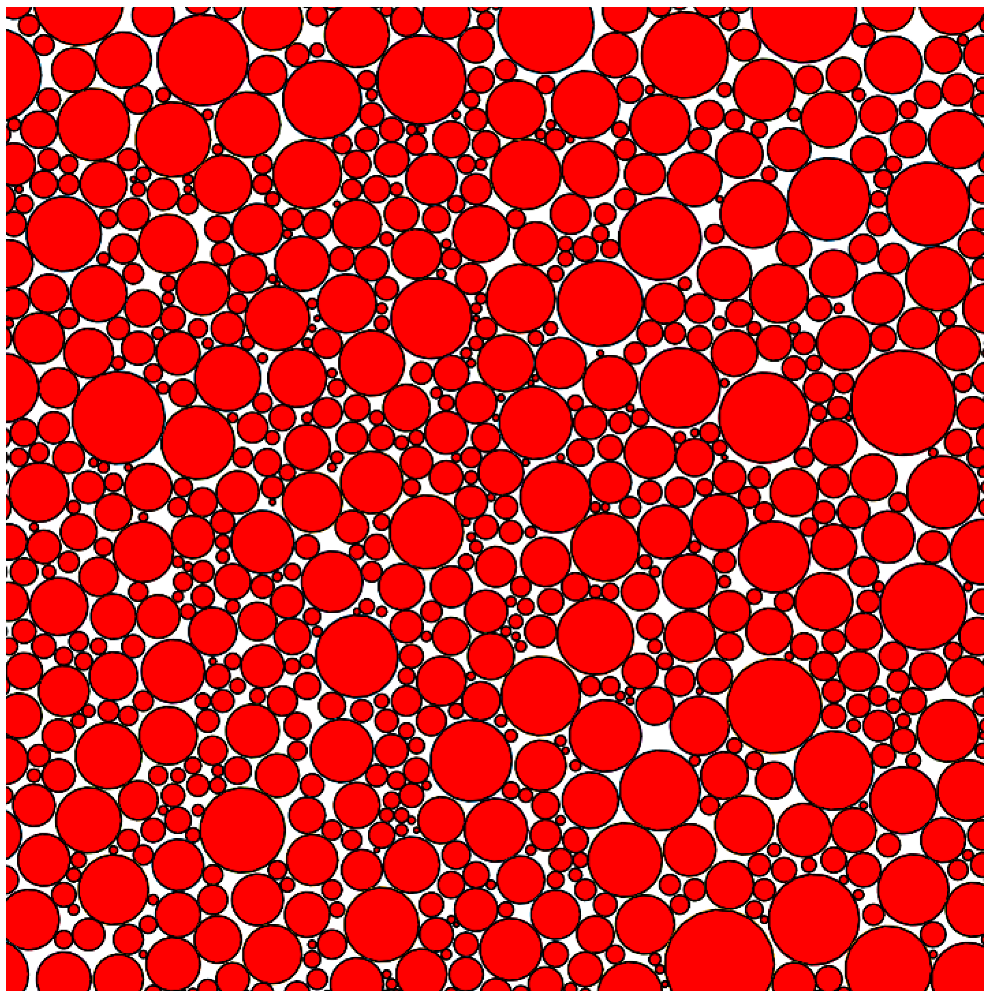
To calculate the powder bed void fraction, the powder size distribution was first achieved through image analysis of the SEM photo of the 316L powders [
6], as shown in
Figure 4. Based on the information of powder size distribution, the powder bed packing pattern was generated by the advancing front method, as shown in
Figure 5. The powder bed void fraction was then determined by image analysis of the packing pattern. The packing patterns with 400, 600, 800, 1000, 1200 powders were generated, in order to analyze the effects of powder number on the void fraction. The estimated powder bed void fractions for these patterns are shown in
Table 2. It can be observed that the number of powders does not have a clear influence on the estimated powder bed void fraction. In this study, the average value of 14.13% was used in the modeling process.
With the powder bed void fraction and solid material properties as inputs, the material properties of powder bed were calculated, as shown in
Table 3. The solid material properties at the melting temperature [
26] were used for the calculation, which are also shown in
Table 3.
The laser power absorptivity is affected by many parameters in LPBF, including the process parameters, profile of the powder bed surface, and characteristics of the laser source [
27]. Therefore, for a different experimental setup, there should be a different value of laser absorptivity. Since the specific laser absorptivity for the cases in this study were not given in [
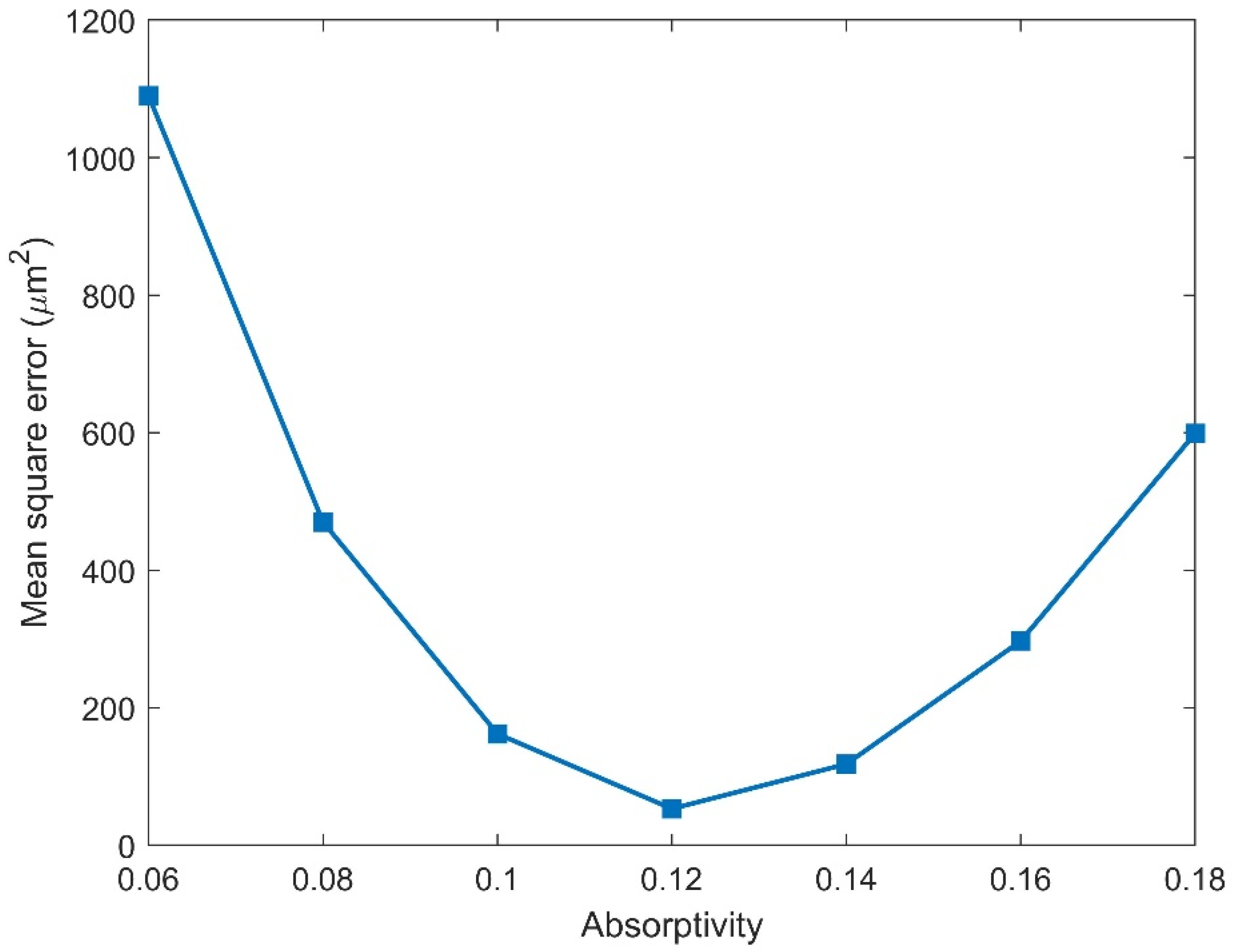
6], a trial-and-error method was employed to determine the laser absorptivity for this study. The predicted molten pool width by the point-moving heat source model, under the process conditions in
Table 4, was compared with the experimental results. The sensitivity of the mean square error for the predictions of the cases in
Table 4 to the laser absorptivity is shown in
Figure 6. It can be observed that when the laser absorptivity is 0.12, the mean square error was lowest. Thus, the value 0.12 was used in this study as the laser absorptivity.
With the powder bed material properties, laser absorptivity and process conditions, the molten pool width and re-melted depth for the cases in
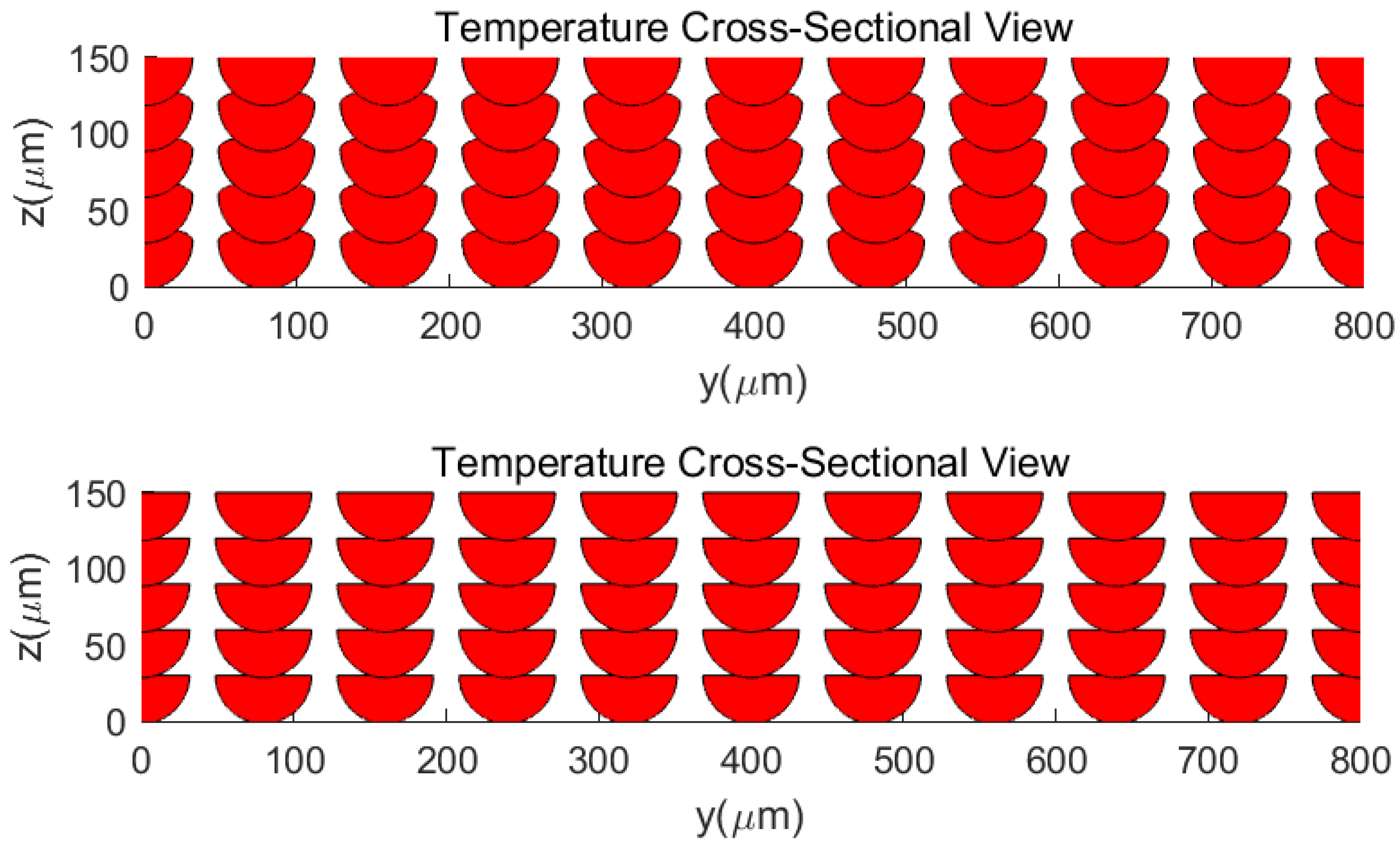
Table 1 were determined. Based on the assumption of the shape of molten pool cross sections, the specific geometries of the molten pool cross sections with cap areas were then obtained. (The ratio between cap height to molten pool depth was determined as 0.3 by minimizing the mean square error of the predictions of porosity for the last six cases in
Table 1.) Multiple molten pool cross sections were then plotted on a transverse cross section of the part to generate the overlapping pattern, as shown in
Figure 7. For comparison, the molten pool overlapping pattern, without considering cap area was also shown in
Figure 7. The lack-of-fusion area factions for different cases in
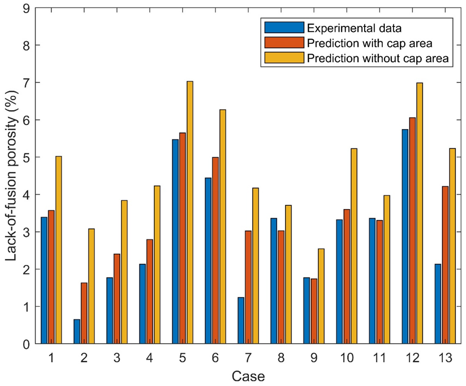
Table 1 were then obtained by image analysis of the overlapping patterns. The lack-of-fusion porosity of the part under various process conditions was finally calculated as the product of the lack-of-fusion area fraction and the powder bed void fraction. The comparison among predictions considering cap area with experimental measurements, and predictions without the cap area are shown in
Figure 8 and
Table 1. It can be observed that the predictions considering cap area are always closer to the experimental data than the predictions without the cap area, and show a better predictive accuracy when considering the cap area of molten pools. The calculation time of the proposed analytical model for 5 scan layers with 10 tracks in each layer was less than 1 min when running on a laptop with a 3.4 GHz Intel i5 processor. However, the calculation time of the numerical model developed in [
16] for five layers, with five tracks in each layer, was about 5 h when running on a computer whose processer was Intel i7 with a 3.4 GHz frequency. Thus, the proposed analytical method shows a high computational efficiency.
The proposed analytical modeling method in this study has showed an acceptable predictive accuracy and high computational efficiency for the prediction of lack-of-fusion porosity, without resorting to numerical iterations. In the future, temperature-dependent material properties and process conditions-dependent laser absorptivity can be considered in this model, in order to increase its predictive accuracy.
4. Conclusions
In this study, a physics-based analytical modeling method is proposed for the prediction of lack-of-fusion porosity in laser powder bed fusion metal additive manufacturing, with the consideration of the existence of the cap portion in solidified molten pools, influence of powder bed characteristics on material properties, and the existence of un-melted powders in the lack-of-fusion portion of the part. The packing pattern in the powder bed was generated by an advancing front method based on the information of powder size distribution. The powder bed void fraction was then obtained by image analysis of the packing pattern. The powder bed material properties were calculated by analytical models based on the information of solid material properties and powder bed void fraction. The molten pool cross sections were assumed to be dual half-elliptical. The molten pool dimensions were obtained by a point-moving heat source model. The ratio between cap height and molten depth was determined by regression analysis. The specific geometries of molten pools were then determined based on the shape assumption and the values of cap height, molten pool width and re-melted depth. By image analysis of the overlapping pattern of molten pool cross sections of multiple tracks and layers, the lack-of-fusion area fraction was obtained. The lack-of-fusion porosity of the part was the product of the lack-of-fusion area fraction and powder bed void fraction.
Predicted lack-of-fusion porosity under various combinations of process conditions were validated against the experimental measurements of 316L stainless steel in LPBF and the predicted results without considering cap area. The predictions had a better agreement with experimental data than predictions without considering cap area, which shows a better predictive accuracy of the proposed model. Additionally, the analytical method in this study shows a high computational efficiency because it does not include any numerical calculations. In brief, the proposed analytical modeling strategy can work as an efficient tool for the prediction of porosity in LPBF induced by lack-of-fusion defects. In addition, it can be an ideal basis for the study of computational modeling for additive manufacturing processes.


