Article

Study on Micro-Structure and Tensile Mechanical Properties of Dissimilar Metal Weld Joint Connecting Steam Generator Nozzle and Safe-End

1
Applied Mechanics and Structure Safety Key Laboratory of Sichuan Province, School of Mechanics and Engineering, Southwest Jiaotong University, Chengdu 610031, China
2
Taishan Nuclear Power Joint Venture Co., Ltd., Jiangmen 529200, China
3
Suzhou Nuclear Power Research Institute, Suzhou 215004, China
*
Authors to whom correspondence should be addressed.
Crystals 2021, 11(12), 1470; https://doi.org/10.3390/cryst11121470
Submission received: 22 October 2021 / Revised: 10 November 2021 / Accepted: 21 November 2021 / Published: 26 November 2021
(This article belongs to the Special Issue Investigation on the Formation and Properties of Steels)

Abstract

:
The safe-end of a steam generator (SG) nozzle dissimilar metal weld (DMW) for pressurized water reactors (PWRs) is the weakest point of failure which is crucial for the safe operation of a nuclear power station. Related to materials micro-structures, a uniaxial stress–strain relationship is the basic input parameter for nuclear power plant design, safety evaluation, and life management. In this paper, the micro-structure and tensile mechanical properties of a DMW of a European pressurized water reactor (EPR) were studied. Vickers hardness tester, optical microscope, and electron back scatter diffraction were used to analyze the micro-structure of the DMW joint. In addition, the residual strain of the DMW joint base material, heat-affected zone, weld metal, and fusion boundary region were studied. Based on digital image correlation (DIC) technology, tensile mechanical properties of the DMW joint were obtained. The results show that an accurate tensile stress–strain relationship of dissimilar metal welded joints can be obtained by using the DIC technique, the weld is the relatively weak link, and the residual strain is concentrated in the heat-affected zone. This study provides valuable engineering information regarding nuclear power plant design, in-service performance testing, and structural analysis and evaluation of welds containing defects.

1. Introduction

Welding joints are widely used in various key structures, such as steam generators (SG) and reactor pressure vessels (RPV) in reactor engineering. Nickel-based alloy and austenitic stainless steel are mainly applied for welding due to their high temperature resistance, corrosion resistance, and applicable mechanical properties. According to the differences in welding alloy materials and base materials (BMs), welding joints can be divided into a same-metal welding joint or a dissimilar metal weld joint (DMW joint) [1,2]. The DMW joint includes a fusion boundary (FB), heat-affected zone (HAZ), weld material (WM), and two kinds of BMs [3,4,5]. Its material, structure, and service environment are complex, but it is possible to detect service-induced defects. Research on its mechanical behavior has important engineering value.
It is well known that the FB of a DMW joint exhibits a complex micro-structure, such as the composition gradient across the FB, the high residual strain adjacent to the FB, the change of grain boundary characteristic distribution in the HAZ of the stainless steel, etc. Electron backscatter diffraction (EBSD) [6] texture testing technology enables crystallographic orientation analysis while observing the tissue morphology of specimens, enabling the micro-structure to be correlated with crystallographic information, and is a powerful analytical tool for rapid and accurate material texture measurements [7,8]. This technology has been widely used in metallurgy, material processing, and other fields [9,10], especially in grain boundary characteristic distribution and residual strain distribution of welding joints [11].
Related to materials micro-structures, a uniaxial stress–strain relationship is the basic input parameter for nuclear power plant design, safety evaluation, and life management. Generally, the uniaxial tensile properties are obtained by uniaxial tensile tests. However, a heterogeneous micro-structure brings about certain difficulties in the measurement of local mechanical properties of the DMW joint. The strain information of BMs, HAZs, and WM cannot be obtained by using the traditional contact strain extensometer. The width of a DMW with a narrow-gap automatic welding process is only about 10 mm; therefore, it is impossible to obtain the uniaxial stress–strain relationship curve by a traditional standard specimen uniaxial tensile test. In recent years, the rapid development of computer technology has promoted the gradual maturity of 3D digital technology. The digital image correlation (DIC) technology used for measuring surface deformities has the characteristics of “non-contact” [12,13] and “full-field” [14,15,16] displacement information on the surface. It is the most promising 3D data acquisition method in current engineering applications and can be used to measure tensile mechanical properties of welding joints.
A nickel-based alloy (INCONEL 52) was used to connect an austenitic stainless steel (Z2 CND 18.12 N2 controlled) safe-end of a primary circuit piping to a low alloy steel (20MND 5) SG nozzle in European pressurized water reactor (EPR) nuclear power plants. In this paper, the micro-structure, residual stress, Vickers hardness, and the uniaxial tensile mechanical properties of an SG safe-end DMW joint prepared by narrow-gap gas-tungsten arc welding were studied. The accurate characterization of the material mechanical properties and micro-structure is helpful to understand the complex local damage and fracture behavior of the DMW joint and aids in evaluating the structural integrity of DMW joints with defects.

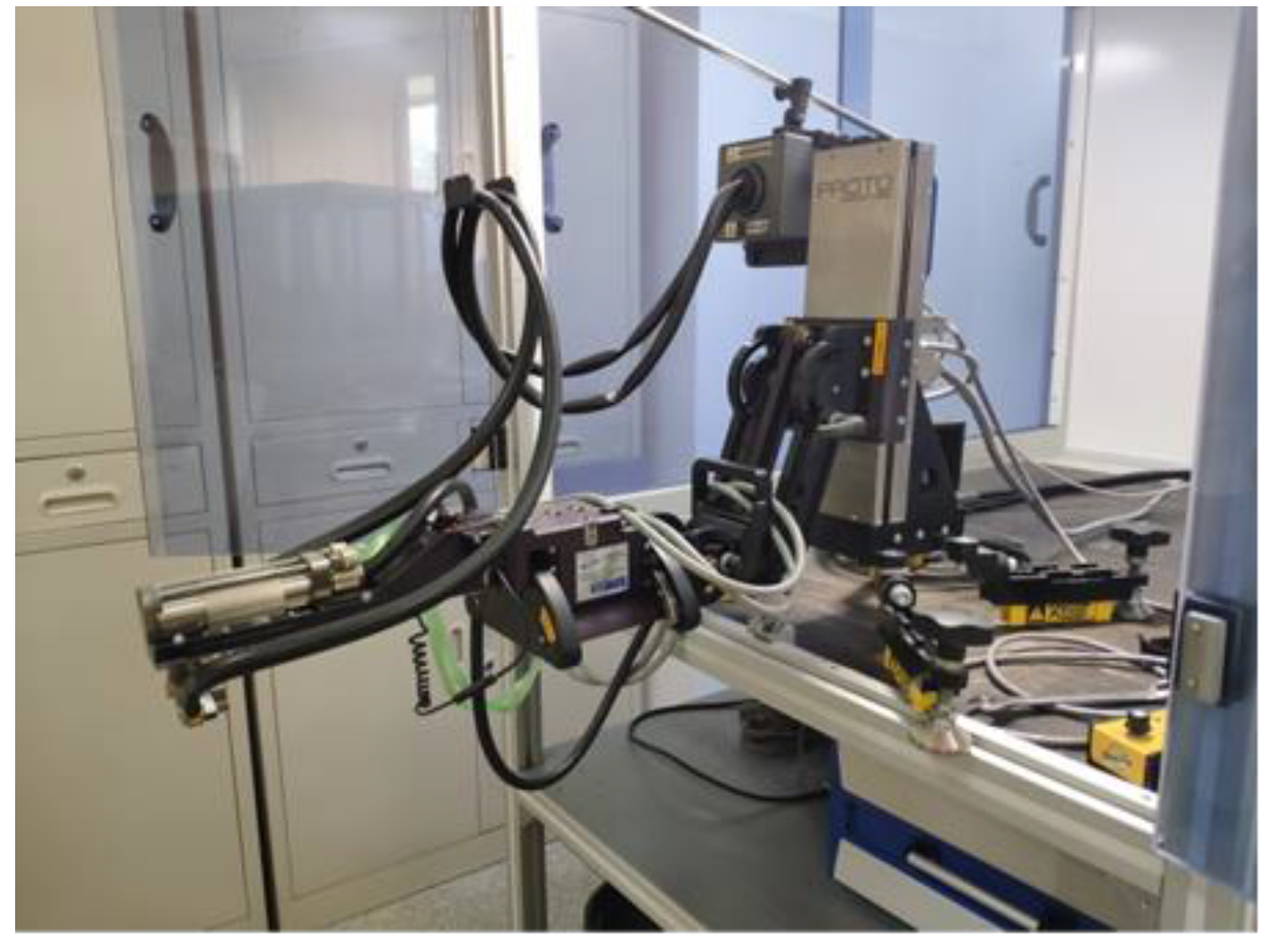
2. Materials and Methods

The structure and size of the DMW joint between the SG nozzle and safe-end of an EPR nuclear power station is presented in Figure 1 and Figure 2. The materials of the primary side nozzle of the steam generator and safe-end pipe were 20MND 5 manganese nickel molybdenum alloy steel and Z2 CND 18.12 austenitic stainless steel with nitrogen controlled, respectively. The DMW joint was fabricated by narrow-gap gas tungsten arc welding using INCONEL 52 as the WM and adopted φ 0.9 mm welding wire. The minimum preheating temperature of the specimen was 175 °C, and the maximum interlayer temperature during welding was 225 °C. After making the weld, the heat treatment temperature ranged from 595 °C to 620 °C. The heating rate was less than or equal to 55 °C/h, the cooling rate was less than or equal to 55 °C/h, and the discharging temperature was 350 °C. The width of the WM was 9.5–11 mm, and the thickness of the DMW was approximately 97 mm. A stainless steel cladding layer was buttered on the inner surface of the SG nozzle. The chemical composition of BMs and WM in weight is shown in Table 1.
In order to obtain the tensile stress–strain curve of the DMW joint, three tensile straight flat (SF) specimens—as shown in Figure 3—were processed, and the weld was at the center of the length of the specimen. The isometric width, thickness, and length of the SF specimens were 8 mm, 1 mm, and 30 mm, respectively.
The typical positions (from “A” to “F”, as shown in Figure 3) of micro-structures of DMW joint materials were observed with an optical microscope (in Figure 4, “A” to “F”). 20MND 5 was etched by 4% nital (96 mL of ethanol and 4 mL of nitric acid); Z2 CND 18.12 and WM INCONEL 52 were etched by a solution made of 16 g ferric chloride, 11 mL water, 80 mL hydrochloric acid, and 2 mL nitric acid.
The micro-hardness distribution of the DMW joint was measured using a Qness Q10 A+ micro-hardness instrument with a load of 1000g and a holding time of 10 s. In the direction of line “L” in Figure 4, the hardness distribution of the DMW joint was obtained by measuring points at 0.4 mm intervals.
The residual stress of a DMW joint is also an important part of its mechanical properties. Although there are many methods to detect the macro residual stress, the X-ray stress diffraction method is the most typical. This method is widely used in the world because of its rigorous theoretical basis, mature experimental technology, and reliable measurement results. Compared with other detection and analysis methods, X-ray has the advantages of non-contact, non-destructive, high accuracy, and repeatable detection. Therefore, the advanced Proto iXRD portable X-ray stress meter, shown in Figure 5, was used to test and obtain the welding residual stress of a narrow-gap automatic welding seam.
Considering that the depth of X-ray penetrating the material was shallow and that the surface state had a direct impact on test results, the surface of the test piece was required to be smooth, clean, and free of attached dirt, oil film, and oxygenated skin. Therefore, the surface of the test piece was subject to corrosion treatment before the test. Figure 6 shows the test site of residual stress of the test block.
The grain boundary characteristic distribution and residual strain distribution of the DMW joint were analyzed by the EBSD. The specimens for the EBSD analysis were mechanically ground using SiC papers up to 2000 grit, polished using 1 μm diamond paste, polished using silk, and finally, polished by 0.04 μm colloidal silica slurry. The EBSD analysis of 20MND 5 was performed with a step size of 0.5 μm at a voltage of 20 keV. Due to a huge difference in grain size between 20MND 5 and WM INCONEL 52, the EBSD analysis was performed with a step size of 5 μm at a voltage of 20 keV to show the micro-structure of WM INCONEL 52 and Z2 CND 18.12 N2 controlled, while a step size of 2 μm was used for the precise analysis of the FB region on the side of 20MND 5. The EBSD analysis of the FB region on the side of the austenitic stainless steel (Z2 CND 18.12 N2 controlled) was performed with a step size of 6 μm at a voltage of 20 keV.
The SHIMADZU AG-IS (30kN) universal material testing machine was used to perform the tensile testing for the DMW joint. The strain extensometer 3542-025M-025-ST (a gauge length of 25 mm and a range of +25% ~−10%) was used to measure the strain of the SF specimen. The accuracy of both the testing machines and strain extensometers were 0.5. Before the test, the SF specimens were sprayed with white matte paint, then the black ink was sprayed evenly on the surface of the SF specimens with a spray gun. Speckles of a uniform size, different shapes, and clear edges, as shown in Figure 7, were produced on the surface of the SF specimens, which were key information features used to calculate displacement during DIC deformation measurement. During DIC measurement, both the overall strain of the welded joint and the strain distribution in the weld zone, base metal, and heat-affected zone could be determined by obtaining the deformation information of the region of interest in the distance segment during tensile loading. During the DIC test, the speckled area of interest of the DMW joint specimen was photographed at a sampling frequency of 1Hz. When the speckle began to fall off, the corresponding measurement data were absent. The ARAMIS system was used to measure the strain of the SF specimens. Figure 8 illustrates the experimental device, which consists of the testing machine, the ARAMIS system, and the SF specimen.

3. Results and Discussion

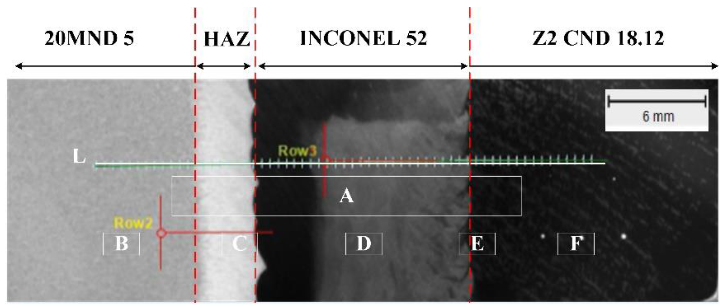
3.1. Metallographic Examination

There is an obvious HAZ within 3 mm from the 20MND 5 BM to the FB, as shown in Figure 9A. It was clearly observed in Figure 9A that the typical dendritic grain of INCONEL 52 grew approximately perpendicular to the weld FB.
The micro-structures of the BMs, WM, FBs, and HAZs are shown in Figure 9B–F. The BM 20MND 5 contained a large amount of tempered bainite tissue, as shown in Figure 9B. The BM Z2 CND 18.12 material contained a large number of twin austenite grains, as shown in Figure 9F. Figure 9D shows the as-cast dendrite structure in the WM INCONEL 52. The element diffusion and heat flow in the welding process made the interface region of different materials form a complex micro-structure. Figure 9C shows the micro-structure of the 20MND 5/INCONEL 52 interface area, and the heat-affected zone near the interface 20MND 5 side was bainite structure. Figure 9E shows the micro-structure of the INCONEL 52/Z2 CND 18.12 interface area. The micro-structure of Z2 CND 18.12 near the interface was mainly as twin austenite grains.

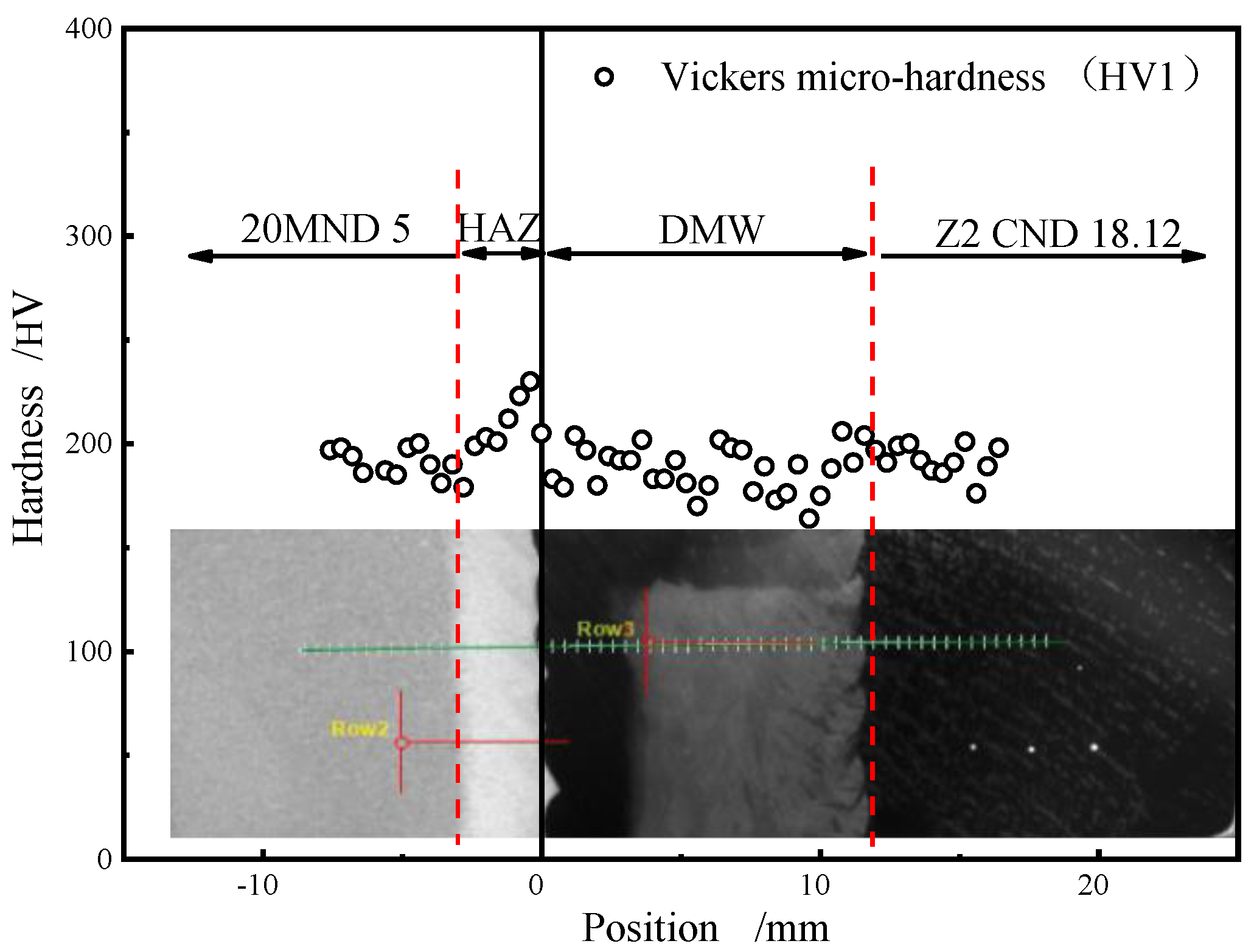
3.2. Vickers Hardness Test

Figure 10 shows the Vickers hardness distribution along the DMW joints. The hardness values of base metals 20MND 5 and Z2 CND 18.12 are in the range of 179–201 HV and 176–204 HV, respectively. From the hardness distribution of the three interface areas, it can be seen that there were large hardness changes in the interface area, especially in the 20MND 5/INCONEL 52 interface area. On the 20MND 5 side near the interface (the heat-affected zone), there was a local high hardness zone with a width of about 1.2 mm and a hardness value of about 230 HV. The existence of a bainite micro-structure lead to the formation of a high hardness region. In the heat-affected zone of 20MND 5, within the range of 1.5–2.8 mm from the interface of 20MND 5/INCONEL 52, the hardness value rapidly decreased from a peak value of 230 HV to a minimum value of 179 HV. The sharp change of hardness is mainly due to the transformation from bainite to tempered bainite in local materials, and the change of micro-structure in these areas is caused by the rapid reduction of local temperature during welding. With an increased distance, it can be seen that the hardness essentially does not change in the area 3–7.6 mm away from the interface and is maintained at a low hardness value of about 200 HV. This means that the 2.4 mm wide area is the local softening zone of dissimilar metal welded joints. The formation of the local softening zone was due to the high tempering temperature in this local zone, resulting in diffusion and migration of carbon and other elements, which reduced the hardness of the tempered bainite micro-structure. A tempering softening zone usually occurs in the heat-affected zone of low alloy steel. On the INCONEL 52 side near the interface, the hardness value rapidly decreased from a peak value of 230 HV to a lower value of 183 HV (the hardness level of INCONEL 52) from the 20MND 5/INCONEL 52 interface to 0.4 mm away from the interface. This was related to the chemical composition and micro-structure of the interface material.

3.3. Residual Stress Test

There were 11 measuring points in the axial direction of the outer wall of the test block (Figure 11). The distance between the base metal and the weld width was greater than twice the weld width, with each place measured twice. The test results are shown in Figure 12.
It can be seen from Figure 12 that the highest residual stress of the dissimilar metal welded joint of narrow-gap automatic welding is in the heat-affected zone on the side of low alloy steel. The residual stress was low because the dissimilar metal weld underwent 4 h of intermediate tempering from 250 °C to 400 °C and a final heat treatment from 595 °C to 620 °C for 2.75 h to 3.25 h.

3.4. EBSD Analysis

Figure 13 shows the inverse pole figures (IPFs), kernel average misorientation (KAM) maps and grain boundary character distribution (GBCD) maps in BMs, the HAZ of the 20MND 5, the FB region of the 20MND 5/INCONEL 52 dissimilar welding structure, WM INCONEL 52, and theFB region of the INCONEL 52/Z2 CND 18.12 N2-controlled and Z2 CND 18.12 N2-controlled dissimilar welding structures. This shows that the residual stress in the heat-affected zone of 20MND 5 is high, which was in good agreement with the test results in Figure 12.

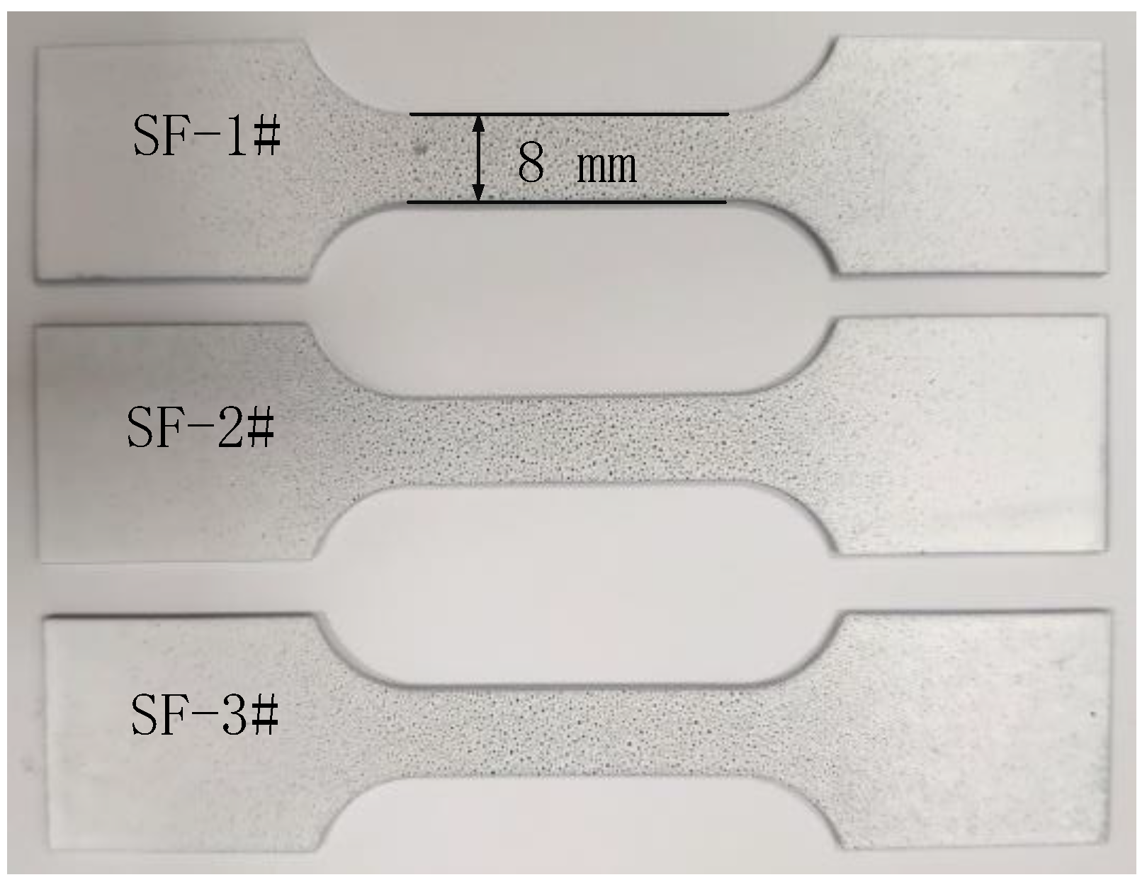
3.5. Uniaxial Tensile Test Based on DIC

Uniaxial tensile tests of three SF specimens were completed. The non-uniform deformation law of DMW joint was analyzed by GOM-correlation analysis software. As shown in Figure 14, strain localization and damage first appeared in the weld area and continued to expand with increased tensile stress; the specimens then began to necking at the position where the local damage was the most serious. As the loading continued, the speckle deformation was serious, but it can still be seen that the maximum deformation in the weld area reached 0.8635, and the maximum average strain in the corresponding region of interest was only 0.2046. Since the yield strength of 20MND5 material is higher than INCONEL 52 and Z2 CND 18.12 and austenitic stainless steel has good ductility, the main deformation occurred at the weld and austenitic stainless steel side during the tensile process, which was also consistent with the cloud diagram test results of the specimen surface strain in Figure 14. Varying information for tensile strain of a welded joint with a loading process was obtained according to DIC measurement. The average deformation data of different areas of a welded joint were obtained based on the averaging idea and zoning extensometer method, that is, three virtual overall extensometers were selected at equal intervals (2 mm) along the width direction of a welded joint, 15 measurement points were selected on each extensometer, and the overall extensometer was divided into zone extensometers for metallographic measurement of the weld, HAZ and BM. In order to obtain the strain distribution on the specimen section, 81 measuring points were selected in the width direction of the specimen, as shown in Figure 15. Figure 16 shows the strain change curves in the width direction at the middle of the weld at different tensile times. The Young’s elasticity modulus, the yield strength, the tensile strength, and the elongation of the DMW joints integrity are listed in Table 2.
The uniaxial tensile stress–strain curves obtained by the DIC technology were consistent with the measurement results obtained by the strain extensometer. In particular, the DIC technology can be used to observe the full-field strain of the specimens, the place where stress concentration occurs, and the failure process of the specimens during the entire tensile testing. Figure 17 shows the stress–strain curves of an SF specimen of a DMW joint tested by DIC and the comparison results measured by an extensometer.
Figure 18 shows the relationship between stress and average strain in the low alloy steel base metal area, austenitic stainless steel base metal area, and weld area. It can be seen that the yield stress in the weld area was the lowest, and the specimen was the most damaged at the weld. This also reveals the reason why the specimen broke at the position of the weld.

4. Conclusions

The DMW joint located between the SG nozzle and the safe-end of an EPR were studied in this paper. The micro-structure of the DMW joint was analyzed by using Vickers hardness tester, optical microscope, Proto iXRD portable X-ray stress meter, and EBSD. The strain distribution of the DMW joint SF specimens during tensile tests were obtained by the DIC technique. The following conclusions were drawn from this investigation:
(1) The distribution of micro-structure, Vickers hardness, residual stress and yield strength of a DMW joint are very uneven.
(2) The Proto iXRD portable X-ray stress meter was used to test the residual stress of the DMW joint. The results showed that the residual stress of the DMW joint based on the use of narrow-gap automatic welding was lower, and the residual stress of the heat-affected zone was higher than that of the weld.
(3) It was observed by the DIC technology that during the process of the tensile testing for SF specimens of the DMW joint, strain concentration occurred in the HAZs of BMs and WM. All failures of the SF specimens occurred at the weld locations. The varying information of the tensile strain of a welded joint with a loading process was obtained according to DIC measurement. The average deformation data of different areas of a welded joint were obtained based on the averaging idea and zoning extensometer method, then used to obtain the relationship between stress and average strain in the low alloy steel base metal area, austenitic stainless steel base metal area, and weld area.

Author Contributions

W.X., conceptualization, project administration, methodology, data curation, writing—review and editing, funding acquisition; S.Q., methodology, investigation, software, validation, writing—original draft preparation; L.C. and J.S., methodology, writing—original draft preparation, investigation; X.L. and L.Q., methodology, investigation, software; Y.W., F.N. and W.Y., methodology, data curation, supervision, writing—original draft preparation, writing—review and editing. All authors have read and agreed to the published version of the manuscript.

Funding

This research was funded by National Nature Science Foundation of China (L.C., Grant No. 11872320), Policy Guidance Program of Jiangsu Province (Y.F., Grant No. BZ2020057).

Data Availability Statement

The data presented in this study are available on request from the corresponding author.

Acknowledgments

The work was carried out with the use of equipment and software from the Suzhou Nuclear Power Research Institute. The authors are grateful to Min Yu and Minyu Fan for their help in measuring using DIC.

Conflicts of Interest

The authors declare no conflict of interest.

References

  1. Zhu, R.; Wang, J.; Zhang, Z.; Han, E. Stress corrosion cracking of fusion boundary for 316L/52M dissimilar metal weld joints in borated and lithiated high temperature water. Corros. Sci. 2017, 120, 219–230. [Google Scholar] [CrossRef]
  2. Ma, C.; Peng, Q.; Mei, J.; Han, E.H.; Ke, W. Microstructure and corrosion behavior of the heat affected zone of a stainless steel 308L-316L weld joint. J. Mater. Sci. Technol. 2018, 34, 1823–1834. [Google Scholar] [CrossRef]
  3. Chung, W.; Huang, J.; Tsay, L.; Chen, C. Micro-structure and Stress Corrosion Cracking Behavior of the Weld Metal in Alloy 52-A508 Dissimilar Welds. Mater. Trans. 2011, 52, 12–19. [Google Scholar] [CrossRef] [Green Version]
  4. Ming, H.; Zhang, Z.; Wang, J.; Han, E.; Wang, P.; Sun, Z. Micro-structure of a safe-end dissimilar metal weld joint (SA508-52-316L) prepared by narrow-gap GTAW. Mater. Charact. 2017, 123, 233–243. [Google Scholar] [CrossRef]
  5. Zhu, R.; Wang, J.; Zhang, L.; Zhang, Z.; Han, E. Stress corrosion cracking of 316L HAZ for 316L stainless steel/Inconel 52M dissimilar metal weld joint in simulated primary water. Corros. Sci. 2016, 112, 373–384. [Google Scholar] [CrossRef]
  6. Navid, S.; Morteza, S.; Behzad, N.; Jalal, K.; Szpunar, J.A. EBSD observations of microstructural features and mechanical assessment of INCOLOY 825 alloy/AISI 321 stainless steel dissimilar welds. J. Manuf. Process. 2020, 60, 86–95. [Google Scholar]
  7. Justinger, H.; Hirt, G. Estimation of grain size and grain orientation influence in microforming processes by Taylor factor considerations. J. Mater. Process. Technol. 2009, 209, 2111–2121. [Google Scholar] [CrossRef]
  8. Xu, W.; Ferry, M.; Mateescu, N.; Cairney, J.M.; Humphreys, F.J. Techniques for generating 3-D EBSD micro-structures by FIB tomography. Mater. Charact. 2006, 58, 961–967. [Google Scholar] [CrossRef]
  9. Guo, A.; Misra, R.D.K.; Liu, J.; Chen, L.; He, X.; Jansto, S.J. An analysis of the micro-structure of the heat-affected zone of an ultra-low carbon and niobium-bearing acicular ferrite steel using EBSD and its relationship to mechanical properties. Mater. Sci. Eng. A 2010, 527, 6440–6448. [Google Scholar] [CrossRef]
  10. Humphreys, F.J. Characterisation of fine-scale micro-structures by electron backscatter diffraction (EBSD). Scripta. Mater. 2004, 51, 771–776. [Google Scholar] [CrossRef]
  11. Shamanian, M.; Valehi, M.; Kangazian, J.; Szpunar, J.A. EBSD characterization of the L-605 Co-based alloy welds processed by pulsed Nd:YAG laser welding. Opt. Laser Technol. 2020, 128, 106256. [Google Scholar] [CrossRef]
  12. Ren, S.C.; Morgeneyer, T.F.; Mazière, M.; Forest, S.; Rousselier, G. Effect of Lüders and Portevin–Le Chatelier localization bands on plasticity and fracture of notched steel specimens studied by DIC and FE simulations. Int. J. Plast. 2021, 136, 102880. [Google Scholar] [CrossRef]
  13. He, W.; Wang, C.; Wang, S.; Yao, L.; Cui, L.; Xie, D. Characterizing and predicting the tensile mechanical behavior and failure mechanisms of notched FMLs—Combined with DIC and numerical techniques. Compos. Struct. 2020, 254, 112893. [Google Scholar] [CrossRef]
  14. Sutton, M.A.; Hild, F. Recent Advances and Perspectives in Digital Image Correlation. Exp. Mech. 2015, 55, 1–8. [Google Scholar] [CrossRef]
  15. Romanowicz, P.J.; Szybiński, B.; Wygoda, M. Application of DIC Method in the Analysis of Stress Concentration and Plastic Zone Development Problems. Materials 2020, 13, 3460. [Google Scholar] [CrossRef] [PubMed]
  16. Qi, S.; Cai, L.; Bao, C.; Chen, H.; Shi, K.; Wu, H. Analytical theory for fatigue crack propagation rates of mixed-mode I–II cracks and its application. Int. J. Fatigue 2018, 119, 150–159. [Google Scholar] [CrossRef]
Figure 1. The weld joint between the primary side nozzle of the steam generator and the safe-end.
Crystals 11 01470 g001
Figure 2. The size and configuration of the weld joint.
Crystals 11 01470 g002
Figure 3. The dimensions of a uniaxial tensile SF specimen for a DMW joint.
Crystals 11 01470 g003
Figure 4. Locations for observing micro-structures (from A to F) and measuring micro-hardness (along L line) along the DMW joint.
Crystals 11 01470 g004
Figure 5. The Proto iXRD portable X-ray stress meter.
Crystals 11 01470 g005
Figure 6. The residual stress test site.
Crystals 11 01470 g006
Figure 7. The SF specimens.
Crystals 11 01470 g007
Figure 8. The tensile test of an SF tensile specimen.
Crystals 11 01470 g008
Figure 9. Optical microscope observation of the DMW joint. (A) at 25 magnification, the metallographic structure of welding joint; (B) at 500 magnification, the metallographic structure of the SG nozzle base metal; (C) at 500 magnification, the heat affected zone on the side of SG nozzle and the weld fusion line; (D) at 500 magnification, the metallographic structure of the weld; (E) at 500 magnification, the heat affected zone on the side of safe-end and the weld fusion line; (F) at 500 magnification, the metallographic structure of the safe-end base metal.
Crystals 11 01470 g009
Figure 10. The results of Vickers micro-hardness test of a DMW joint.
Crystals 11 01470 g010
Figure 11. Location of residual stress measuring points on the outer wall of the test block.
Crystals 11 01470 g011
Figure 12. The residual stress measuring results.
Crystals 11 01470 g012
Figure 13. EBSD analyses of different regions of the DMW joint.
Crystals 11 01470 g013
Figure 14. The strain cloud diagram of the specimen.
Crystals 11 01470 g014
Figure 15. Layout diagram of virtual extensometers.
Crystals 11 01470 g015
Figure 16. Strain variation curves in the width direction at the middle of the weld.
Crystals 11 01470 g016
Figure 17. The results of tension stress-strain curves for an SF-DMW joint.
Crystals 11 01470 g017
Figure 18. Relationship curve between stress and average strain in each region of interest.
Crystals 11 01470 g018
Table 1. Chemical composition of the BMs and WM of the DMW joint (%).
MaterialsCSiMnPSCuMoNiCrFeVTiAl
20MND 50.1500.2601.290<0.010<0.0100.0920.4900.7200.026Bal.<0.010--
Z2 CND 18.12 N2 controlled0.0300.5901.8300.023<0.0101.0502.48012.4617.74Bal.---
INCONEL 520.0170.110.290.005<0.0030.02<0.0159.828.99.89-0.210.66
Table 2. Uniaxial tensile testing results of BMs and a DMW joint.
MaterialsSpecimenE/MPaσy/MPaσm/MPaA/mm·mm−1
DMW joint1#196,27641659919.50
2#196,99342762524.00
3#196,29942059223.00
Publisher’s Note: MDPI stays neutral with regard to jurisdictional claims in published maps and institutional affiliations.

