1. Introduction
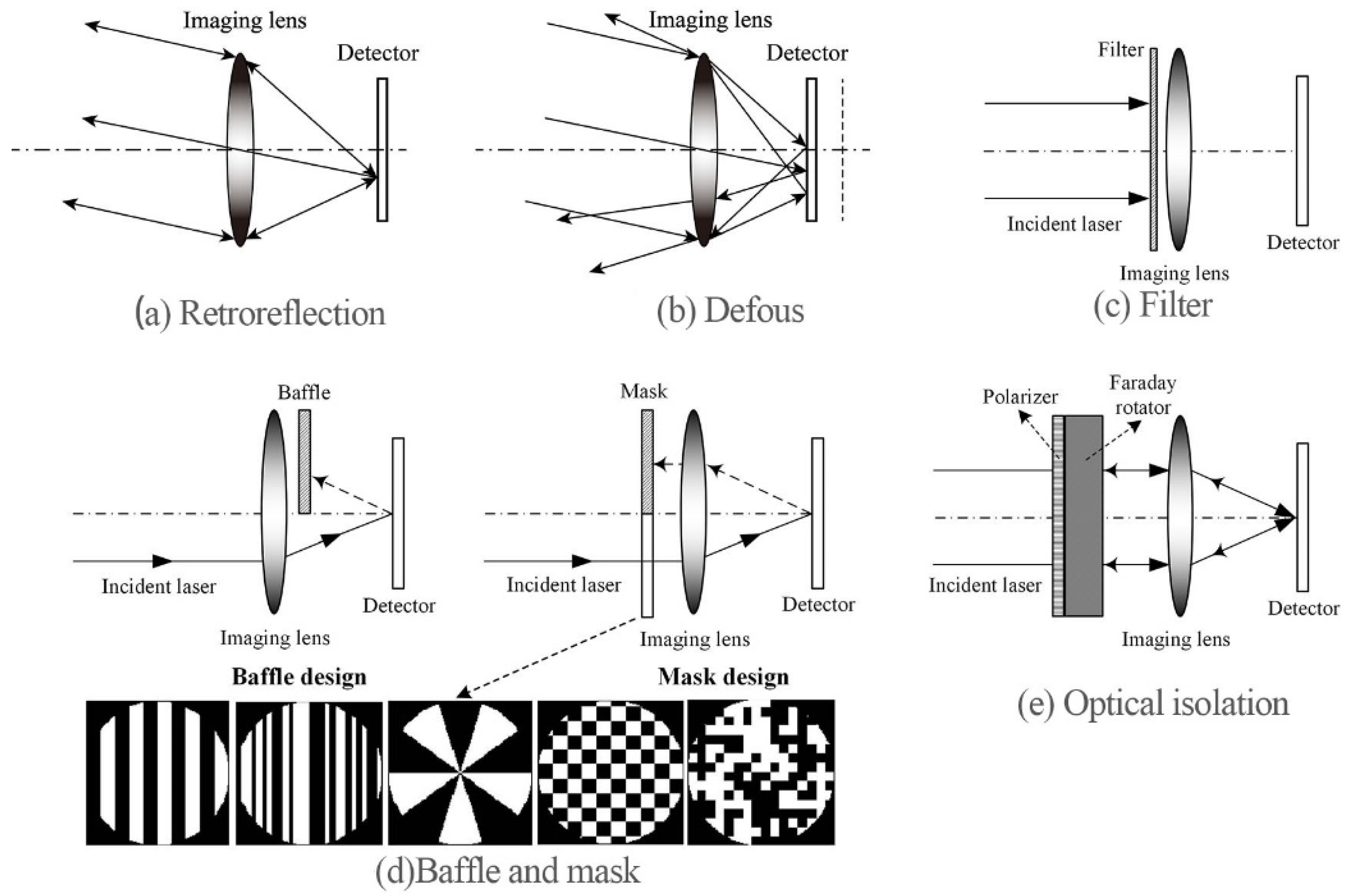
Retroreflection (also known as the cat-eye effect) is a common natural phenomenon. It originally means that cats’ eyes, and other mammals’ eyes, at night will be brighter than the dark background due to the retroreflective natural light. Yet this effect is also widely presented in various photoelectric imaging systems. In conventional photoelectric equipment, the detectors are usually fixed on the focal planes of imaging lenses in order to obtain the best image quality. Although the detectors in conventional photoelectric equipment are usually fixed on the focal plane of an imaging lens in order to obtain the best image quality, they will become a secondary luminous point after being irradiated by the distant reconnaissance laser through the focusing lens. A considerable part of the reflected laser will return according to the original incident light path, as shown in
Figure 1a. The phenomenon that the retroreflective laser intensity is stronger than the background diffused light is called the cat-eye effect of photoelectric imaging equipment [
1,
2,
3,
4,
5,
6,
7]. As a result, the photoelectric imaging equipment is very easy to be found and located by the laser active detection system, so it can be dazzled or blinded by laser [
8,
9]. In the application scenario of anti-terrorism and stability maintenance, the cat-eye effect can be used for high-precision detection of passive imaging equipment such as cameras and telescopes by using actively launched reconnaissance lasers [
9]. At present, the laser reconnaissance system based on cat-eye echo detection technology has been widely used, which poses a severe challenge to the concealment and security of photoelectric imaging equipment [
10]. Therefore, some reasonable and feasible techniques should be adopted to reduce or eliminate the ubiquitous cat-eye effect in the current photoelectric imaging system, thereby reducing the probability of being detected by the laser.
The anti-cat-eye effect imaging techniques of photoelectric imaging systems have been studied. The typical technical scheme is to add different devices such as a filter, baffle, mask and optical isolation in the optical path of the conventional imaging system to prevent the imaging system from generating cat-eye echo, or to place the detector of the conventional imaging system out of focus to reduce the cat-eye echo intensity of the imaging system, as shown in
Figure 1b–e [
2,
11,
12]. Some methods are wavelength dependent (optical filter), while other valid retroreflection reduction is achieved at a cost of severe imaging quality loss (defocus, baffle, mask and optical isolation) [
2,
13]. Take the defocus method to eliminate retroreflection as an example. When the defocus amount is equal to one wavelength, the system MTF starts to show a zero point, and as the defocus amount further increases, the zero points of the defocus MTF curve increase significantly, which indicates that the image quality has been irreversibly degraded [
4].
Recently, computational imaging has been widely applied in many fields. Wavefront coding imaging is one type of computational imaging technology, which can achieve quasi-real-time and high-quality imaging along with a wide range of defocus [
14,
15]. According to previous research [
14,
16], the cubic phase plate can extend the depth of field of the wavefront coding imaging. This paper proposes a novel anti-cat-eye effect imaging technique based on cubic phase plate wavefront coding and proves the superior retroreflection reduction and good imaging quality property of wavefront coding imaging through simulations and experiment.
2. Theoretical Modeling
To further study the characteristics of beam transmission, the wavefront coded imaging system is unfolded into an equivalent 4f optical system to build up a laser path transmission model for the system, as shown in
Figure 2. The formation of retroreflection on the observation plane is recorded as follows.
A Gaussian beam occurs to the front surface of the imaging lens L1 with a beam waist distance defined as .
Through the continuous modification of L1 and the cubic phase plate CPM1, the modulated Gaussian beam is received by a detector with image distance dim.
Considering the defocus of the image plane, the distance between the detector and the focal plane of the system is defined as .
Subsequently, the reflection component of the focused spot on the detector surface is propagated backwards through the phase plate CPM2 and the imaging lens L2, whose parameters are the same as CPM1 and L1, respectively. The cat-eye echo is finally formed on the observation plane with a propagation at the plate of zobser.
The amplitude distribution of the beam on the surface of the imaging lens
L1 can be written as follows [
17,
18]
where ω
0 is the Gaussian beam waist;
k and
λ are the wave vector and the laser wavelength, respectively; ω(
z) and
R(
z) are the spot size and the equiphase surface curvature radius of the Gaussian beam wavefront on the front surface of the imaging lens, respectively.
Assuming that
CPM1 is close to the rear surface of
L1, they can be regarded as a single component with the transmittance function written as
where
P1 (
x,
y) is the generalized pupil function [
14,
16];
α is the phase modulation coefficient;
W20 is the defocus parameter with the wavelength unit
λ
where
L is the size of the pupil;
f is the focal length of imaging lens;
do is the object distance;
di is the image distance. With the assumption of Fresnel approximation, the amplitude distribution on the imaging plane is [
17,
18]
The reflection of the detector silicon substrate, defined as
ρ, is mainly considered to reduce the computational complexity. Therefore, the complex amplitude distribution of the return echo on the phase plate surface is
Through the secondary modulation of the cubic phase plate
CPM2 and the imaging lens
L2, the complex amplitude distribution of the diffractive cat-eye echo formed on the observation plane can be written as
This could serve as the transmittance function for the phase plate and imaging lens, where T2 (ξ,η) = T1 (ξ,η).
3. Simulations and Results
This section provides a set of simulations to assess the imaging performance of the wavefront coding imaging system under defocus conditions and the influence of image plane defocus on the far-field echo of the systems.
Figure 3 shows a comparison of imaging quality between a conventional imaging system and the wavefront coding imaging system under a defocus amount of 10 units.
From the original image,
Figure 3a, an intermediate coded image,
Figure 3b, and a final decoded image,
Figure 3c, are obtained from the conventional imaging system, respectively, where the image can be clearly imaged only near the focal plane. The imaging quality decreases significantly with the increase in defocus as shown in
Figure 3b.
In comparison with that,
Figure 3d,e shows the intermediate coded image and final decoded image obtained through the wavefront coding system, respectively, whose cubic phase plate at the pupil position will produce an intermediate coding image insensitive to defocus, and therefore is uniformly blurred. A clear decoded image can be obtained by inverse filtering the intermediate encoded image [
16].
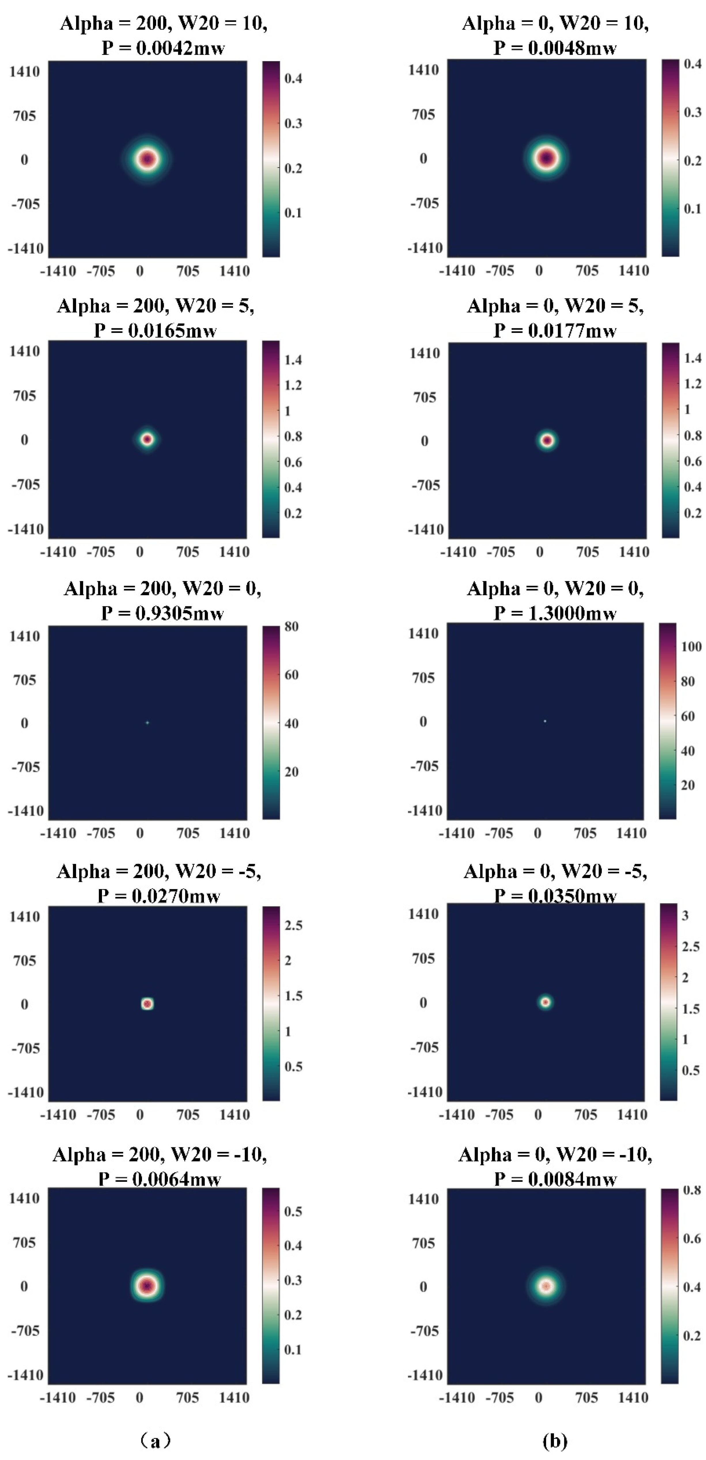
The far-field cat-eye echoes, along with the corresponding echo-detector receiving power, are further obtained for analysis from both the conventional and the wavefront coded imaging system, to further explore the influence of image plane defocus upon the far-field echo of the system. A Gaussian laser beam propagates through an imaging lens under different defocus levels before it is reflected by the detector and observed at a distance of 20 m away from the imaging lens. Under such simulation circumstance, the cat-eye echo profile and intensity distribution are finally detected by an array detector placed on the observation plane, with the simulation parameters shown in
Table 1.
As shown in
Figure 4, the echo-detector receiving power is significantly reduced in a conventional imaging system and wavefront coded imaging system with the increase in the system defocus parameter [
16]. Under the same defocus parameters, while the size of the far-field cat-eye echo from the wavefront coded imaging system is slightly larger than that of the conventional imaging system, its echo detector receiving power is lower than that of the conventional imaging system.
In spite of its theoretical effectiveness in anti-laser active reconnaissance, defocusing will lead to the deterioration in imaging quality, which would seriously restrain its application range for the conventional imaging system. In contrast, the wavefront coded imaging system, with a large depth of field and flexible imaging performances, would compensate for the damage to the imaging quality caused by defocusing, which would greatly enhance the feasibility of defocusing in anti-laser active reconnaissance [
16].
In the case of a 10-unit positive defocus, the echo power of the wavefront coded imaging system is 0.0042 mW, which is 309 times (1.300 mW/0.0042 mW) lower than that of the conventional imaging system in focusing state, while in the case of a 10-unit negative defocus, the echo power is 0.0064 mW, which is 203 times (1.300 mW/0.0064 m W) lower than that of the conventional imaging system in focusing state.
4. Experimental Setup and Results
This section presents the experimental results to assess the imaging performance of conventional and wavefront coding imaging systems under defocus conditions with a comparison of cat-eye echo power between the conventional and wavefront coding imaging system. The experimental settings are as follows:
The CCD detector is bobcat_B6620 produced by IMPERX;
The laser is all solid state 532 nm green laser MGL-N-532/5 W produced by Changchun New Industries Optoelectronics Tech Co., Ltd.;
Other parameters of the optical lens are the same as the simulation parameters of cat-eye echo in
Table 1.
Figure 5 shows the experimental results from the conventional imaging system and wavefront coding imaging system under a 10-unit defocus amount. With the increase in defocus, while the image is completely blurred in the conventional imaging system, a clear decoded image can be obtained by inverse filtering the intermediate coded image in the wavefront coded imaging system.
A comparison of the cat-eye echo between the wavefront coded imaging system and conventional imaging system is further conducted under the condition of a 20 m near-field, whose sketch map of the experimental setup is shown in
Figure 6. The laser beam produced by the 532 nm laser is expanded and propagates to the thin film beam splitter. While one beam split is reflected and detected by a power meter, the other split enters the cat-eye targets in either the wavefront coded imaging system or conventional imaging system, and reflects back along the original way. The reflected beam from the cat-eye system is reflected once again by the thin film beam splitter on a mirror and propagates to another power meter. The echo power of cat-eye could, therefore, be measured by the power meter.
The phase plate is an important component in the wavefront coded imaging system. In the experiment, a cubic phase plate is machined and applied in the wavefront coded imaging system. We disassemble the conventional imaging lens and integrate the cubic phase mask into the aperture position of the system. The plastic material of the phase mask could absorb some visible light. In addition, ring diffraction and energy dispersion of the main lobe are caused by the circle-by-circle traces during the machining of the phase mask. Therefore, we need to measure the transmittance of the phase mask. The far-field diffraction spot of the wavefront coded imaging system is shown in
Figure 7, and the sketch map of the experimental setup to measure the transmittance of phase plate is shown in
Figure 8.
The laser beam produced by the green laser is expanded and propagated to the lens and phase mask, before being focused on the power meter. The average power measured by the power meter in ten seconds is 1.411 mW when the phase mask is not installed in the optical path on the one hand, and is 1.277 mW when the phase plate is installed on the other. The transmittance of the phase mask is therefore 90.5%.
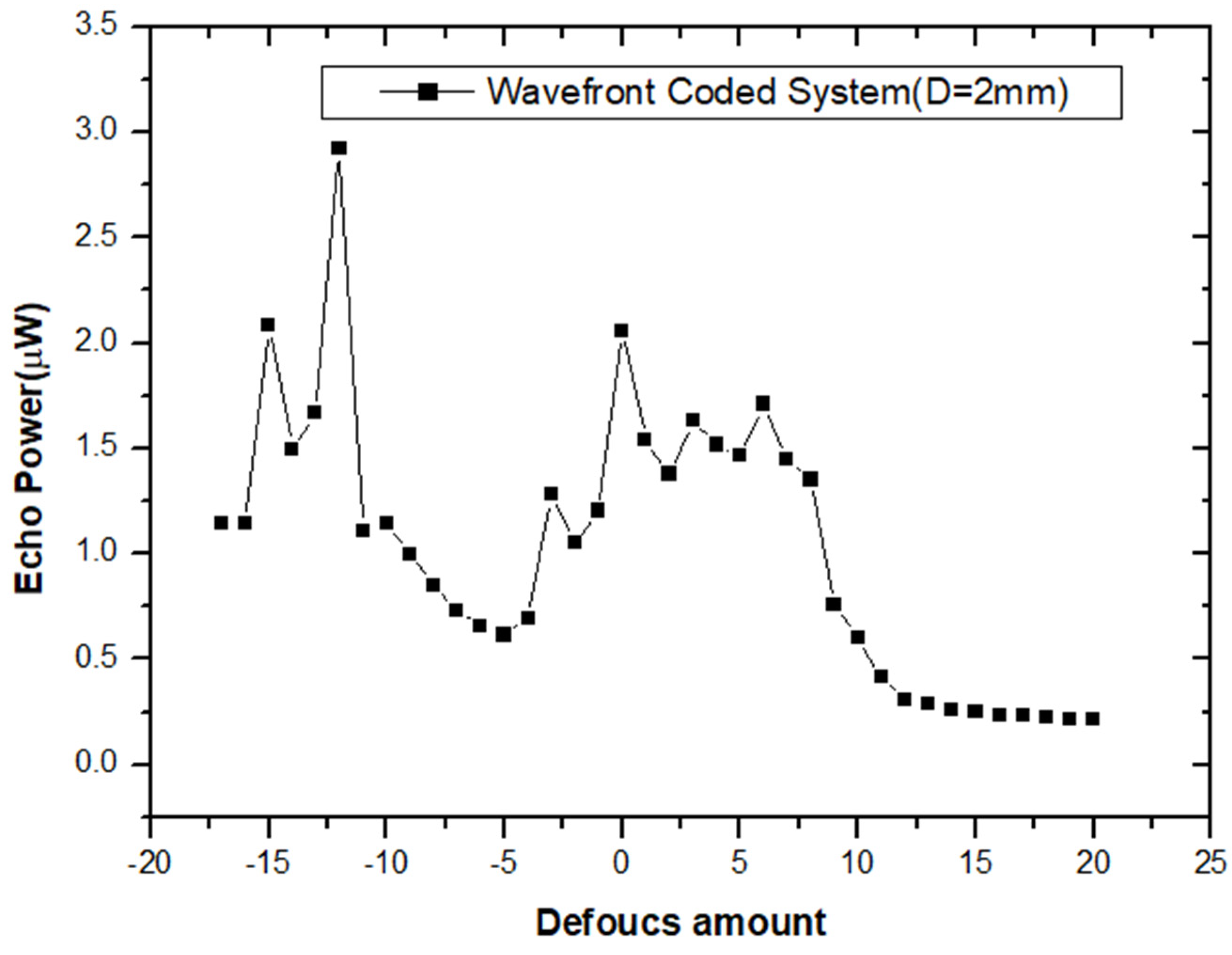
While
Figure 9 demonstrates the comparison of cat-eye echo power between the conventional and wavefront coded imaging systems under different defocus parameters,
Figure 10 shows the cat-eye echo power in the wavefront coded imaging system.
In a focusing state, the echo power maximum of the conventional imaging system is 82.10 μW, while that of the wavefront coded imaging system is 2.058 μW. Considering the influence from the transmittance of the phase plate, the echo power of the wavefront coded imaging system is 2.058 μW/90.5%/90.5% = 2.513 μW, which is 33 times lower than that of the conventional imaging system in focusing state.
Based on the assumption that the image quality of the wavefront coded imaging system with 10-unit defocus is acceptable in the application scenario for target contour tracing with a low requirement on meticulosity, the cat-eye echo could be eliminated. The echo power of the wavefront coded imaging system is 0.6026 μW in the case of the positive defocus of 10 units, and is 82.10 μW × 90.5% × 90.5%/0.6026 μW = 112 times lower than that of the conventional imaging system in focusing state. The echo power of the wavefront coded imaging system is 1.142 μW in the case of the negative defocus of 10 units and is 1.142 μW/90.5%/90.5% = 1.394 μW, which is 59 times lower than that of the conventional imaging system in focusing state. The experimental results are consistent in order of magnitude with the theory.
5. Conclusions
In conclusion, this paper proposes a retroreflection reduction technique based on the wavefront coded imaging system. Simulations and experimental results show that the image is completely blurred with the increase in defocus in the conventional imaging system. In contrast, a clear decoded image can be obtained by inverse filtering the intermediate coded image in the wavefront coded imaging system. Moreover, the wavefront coded imaging system can reduce the echo detector receiving power to two orders of magnitude in comparison with the conventional imaging system. Simulations and experiment results show that a combination of the superior defocus invariant property of wavefront coding technology could produce high-quality imaging with valid retroreflection reduction.
There are still some limitations to the study. Influences from noises are not taken into consideration in the simulation of image decoding reconstruction. Though simulation and experiment results are different in value, they are consistent in scale. This may result from the value difference between the simulated and real Gaussian beam waist radius.
Therefore, we will further modify the simulation results by taking into consideration the noise influences, and by the measurement of the real Gaussian beam waist radius.
Author Contributions
Conceptualization, Q.Y. and X.S.; methodology, Y.W.; software, L.W.; validation, Q.Y., Y.W. and Y.L.; formal analysis, Y.L.; investigation, Q.Y.; resources, Y.W.; data curation, H.Z.; writing—original draft preparation, H.Z.; writing—review and editing, Q.Y.; visualization, L.W.; supervision, X.S.; project administration, Q.Y.; funding acquisition, Q.Y. All authors have read and agreed to the published version of the manuscript.
Funding
This research was funded by the Technology Domain Fund of 173 Project, grant number is 2021-JCJQ-JJ-0284, Anhui Provincial Natural Science Foundation, grant number is 1908085QF275, and Research Project of the National University of Defense Technology, grant number is ZK20-41.
Data Availability Statement
Not applicable.
Conflicts of Interest
The authors declare no conflict of interest.
References
- Rabinovich; William, S. Design and analysis of a diffraction-limited cat’s-eye retroreflector. Opt. Eng. 2002, 41, 1655–1660. [Google Scholar] [CrossRef]
- Mieremet, A.L.; Schleijpen, R.; Putten, F.; Veerman, H. Retroreflection reduction by masking apertures. Opt. Eng. 2010, 49, 1794–1802. [Google Scholar] [CrossRef]
- Ren, X.; Li, L. Recognizing cat-eye targets with dual criterions of shape and modulation frequency. Chin. Opt. Lett. 2011, 9, 041101. [Google Scholar]
- Zhao, Y.Z.; Sun, H.Y.; Song, F.H.; Tang, L.M.; Guo, H.C. Research on the mechanism of reflection characteristics of laser irradiation on cat eye optical lens. Acta Phys. Sin. 2008, 57, 2284–2294. [Google Scholar]
- Fauvel, M.; Chanussot, J.; Benediktsson, J.A. Evaluation of kernels for multiclass classification of hyperspectral remote sensing data. In Proceedings of the 2006 IEEE International Conference on Acoustics Speech and Signal Processing Proceedings, Toulouse, France, 14–19 May 2006. [Google Scholar]
- Jiang, Z.G.; Tan, J.C.; Liang, J.; Cao, D.X.; Zhang, L.Q. Suitability of “Cat’s eye” effect for reconnaissance by the scanning laser. Laser Technol. 2005, 29, 549–551. [Google Scholar]
- Gong, M.; He, S.; Rui, G.; Wei, W. Cat-eye effect reflected beam profiles of an optical system with sensor array. Appl. Opt. 2016, 55, 4461. [Google Scholar] [CrossRef] [PubMed]
- Mieremet, A.L.; Schleijpen, R.; Pouchelle, P.N. Modeling the detection of optical sights using retro-reflection. In Laser Radar Technology and Applications; International Society for Optics and Photonics: Bellingham, WA, USA, 2008. [Google Scholar]
- Titterton, D.H. A review of the development of optical countermeasures. In Technologies for Optical Countermeasures; International Society for Optics and Photonics: Bellingham, WA, USA, 2004; Volume 5615. [Google Scholar]
- Li, L.; Li, H.; Dang, E.; Liu, B. Compressive sensing method for recognizing cat-eye effect targets. Appl. Opt. 2013, 52, 7033–7039. [Google Scholar] [CrossRef] [PubMed]
- Yue, Z.; Wenshen, H.; Bin, Z.; Zuohong, M.; Xiaoming, L.; Xiao, Z. Reflection properties of cat-eye optical system with misaligned reticles. High Power Laser Part. Beams 2012, 24, 1816–1820. [Google Scholar]
- Zhang, Y.; Sun, X.; Lei, P.; Yu, D. Stealth technology of optical-electro imaging devices based on focal shift. Infrared Laser Eng. 2015, 44, 2268–2273. [Google Scholar]
- Wang, L.; Dou, X.; Ye, Q.; Nie, J.; Sun, X. Wavefront coded light-field imaging system to achieve substantial retroreflection reduction and anti-laser blinding property. Opt. Int. J. Light Electron Opt. 2019, 192, 162947. [Google Scholar] [CrossRef]
- Dowski, E.R.; Cathey, W.T. Extended depth of field through wave-front coding. Appl. Opt. 1995, 34, 1859–1866. [Google Scholar] [CrossRef] [PubMed] [Green Version]
- Wang, L.; Ye, Q.; Nie, J.; Sun, X. Optimized Asymmetrical Arcsine Phase Mask for Extending the Depth of Field. IEEE Photonics Technol. Lett. 2018, 30, 1309–1312. [Google Scholar] [CrossRef]
- Wang, L. Tilted wavefront coding system to eliminate the retroreflection with superior imaging property: Publisher’s note. Appl. Opt. 2020, 59, 4732. [Google Scholar] [CrossRef] [PubMed]
- Liu, J.; Tan, J.B.; Zhao, C.G.; Shan, M.G. Impact on Photolithographic Spot Intensity Caused by Collimated Beam with Gaussian Attribute. Chin. J. Lasers 2005, 32, 1627. [Google Scholar]
- Zhou, Z.L. Numerical analysis of Gaussian beam propagating in atmosphere. Laser Technol. 2009, 33, 110–112. [Google Scholar]
| Publisher’s Note: MDPI stays neutral with regard to jurisdictional claims in published maps and institutional affiliations. |
© 2021 by the authors. Licensee MDPI, Basel, Switzerland. This article is an open access article distributed under the terms and conditions of the Creative Commons Attribution (CC BY) license (https://creativecommons.org/licenses/by/4.0/).


 ,
, 


