Article

Fabrication of C/C–SiC–ZrB2 Ultra-High Temperature Composites through Liquid–Solid Chemical Reaction

1
Key Laboratory of Science and Technology on Particle Materials & State Key Laboratory of Multiphase Complex Systems, Institute of Process Engineering, Chinese Academy of Sciences, Beijing 100190, China
2
School of Chemical Engineering, University of Chinese Academy of Sciences, Beijing 100049, China
3
Ganjiang Innovation Academy, Chinese Academy of Sciences, Ganzhou 341000, China
*
Author to whom correspondence should be addressed.
Crystals 2021, 11(11), 1352; https://doi.org/10.3390/cryst11111352
Submission received: 15 October 2021 / Revised: 27 October 2021 / Accepted: 3 November 2021 / Published: 7 November 2021
(This article belongs to the Special Issue Ceramic Matrix Composites)

Abstract

:
In this paper, we aimed to improve the oxidation and ablation resistance of carbon fiber-reinforced carbon (CFC) composites at temperatures above 2000 °C. C/C–SiC–ZrB2 ultra-high temperature ceramic composites were fabricated through a complicated liquid–solid reactive process combining slurry infiltration (SI) and reactive melt infiltration (RMI). A liquid Si–Zr10 eutectic alloy was introduced, at 1600 °C, into porous CFC composites containing two kinds of boride particles (B4C and ZrB2, respectively) to form a SiC–ZrB2 matrix. The effects and mechanism of the introduced B4C and ZrB2 particles on the formation reaction and microstructure of the final C/C–SiC–ZrB2 composites were investigated in detail. It was found that the composite obtained from a C/C–B4C preform displayed a porous and loose structure, and the formed SiC–ZrB2 matrix distributed heterogeneously in the composite due to the asynchronous generation of the SiC and ZrB2 ceramics. However, the C/C–SiC–ZrB2 composite, prepared from a C/C–ZrB2 preform, showed a very dense matrix between the fiber bundles, and elongated plate-like ZrB2 ceramics appeared in the matrix, which were derived from the dissolution–diffusion–precipitation mechanism of the ZrB2 clusters. The latter composite exhibited a relatively higher ZrB2 content (9.51%) and bulk density (2.82 g/cm3), along with lower open porosity (3.43%), which endowed this novel composite with good mechanical properties, including pseudo-plastic fracture behavior.

Graphical Abstract

1. Introduction

Carbon fiber-reinforced carbon (CFC) composites have been widely used in aerospace industries due to their low density and coefficient of thermal expansion, together with their high mechanical strength and excellent thermal shock resistance [1,2]. However, CFC composites are very vulnerable to oxidizing atmospheres over 400 °C, which limits their applications in extreme environments [3]. To effectively enhance the oxidation and ablation resistance of CFC composites at temperatures above 2000 °C, the effects of SiC combined with Zr-based or Hf-based ultra-high temperature ceramics (UHTCs) have been intensively studied [4,5,6]. Several methods of introducing SiC-UHTC ceramics into CFC composites have been investigated, such as polymer infiltration and pyrolysis (PIP) [7], slurry infiltration (SI) [8], chemical vapor infiltration (CVI) [9], and reactive melt infiltration (RMI) [10], in which the RMI process shows the obvious advantages of high densification efficiency and low cost, and is appealing in the manufacturing of low porosity composites with various geometries [11].
Up until now, numerous efforts have been devoted to infiltrating Si or Zr into CFC composites to prepare C/C–SiC or C/C–ZrC composites, respectively [12,13,14,15,16]. However, due to the poor ablation resistance of C/C–SiC, and the weak oxidation resistance of C/C–ZrC, neither of them is suitable to use alone in hypersonic aircrafts. Some studies have demonstrated that infiltrating a Si–Zr alloy to modify CFC composites can simultaneously take advantage of SiC and ZrC ceramics [10]. The ZrO2 skeleton generated by ZrC oxidation exhibits a high melting point (~2700 °C) and extremely low vapor pressure. The SiO2 layer, produced from SiC oxidation, transits to a glassy state above 1175 °C and shows sluggish oxygen diffusion through it. The ZrO2 skeleton is covered by a glassy SiO2 layer, which can cooperatively inhibit the oxygen corrosion of the matrix [17]. Moreover, Si–Zr intermetallic compounds, which partially or completely replace residual Si, can further improve the working temperature limited by the Si softening. Tong et al. modified CFC preforms via RMI with a Si–Zr10 eutectic alloy below 1600 °C, but the enhancement in the ablation resistance of the as-fabricated C/C–SiC composites is finite because of a low ZrC content [18,19,20]. By infiltrating the Si0.87Zr0.13 alloy into porous CFC preforms at 1800 °C, Wang et al. obtained C/C–SiC–ZrC composites with a high strength, due to the gradient structure of the SiC–ZrC matrix [10]. Chen et al. firstly used carbon fabric to prepare C/B4C–C preforms by sol-gel and SI, and then fabricated C/ZrC–ZrB2–SiC composites after the infiltration of ZrSi2 melt into the preforms at 1850 °C. They also investigated the effects of preform pore structure on infiltration kinetics [21]. As aforementioned, in order to introduce more ZrC or ZrB2, hypereutectic Si–Zr alloys are mainly used as the infiltrant, which leads to very high temperatures ( 1800 °C) in the RMI process. However, such high temperatures will increase the uncontrollability during RMI, and eventually result in the following two problems: fiber erosion and infiltration channel chocking [22,23]. Lowering the temperatures of the RMI process can not only reduce the degradation of carbon fibers, but also decrease the cost of preparation.
Therefore, in this study, the C/C–SiC–ZrB2 composites with a higher ZrB2 content were expected to be fabricated at a relatively low temperature, by a combined process of SI and RMI. The porous C/C–B4C and C/C–ZrB2 preforms prepared by SI were infiltrated with the Si–Zr10 eutectic alloy at 1600 °C to achieve C/C–SiC–ZrB2 composites. The SiC matrix was formed by the reaction between C and Si during the RMI process, while the ZrB2 matrix was obtained by in situ generation from the reaction of B4C and Si–Zr10 melt, or by direct introduction via ZrB2 slurry impregnation. The effects of B4C and ZrB2 particles on the microstructural evolution of C/C–SiC–ZrB2 composites were investigated, and the formation mechanism of the SiC–ZrB2 matrix was summarized by schematic diagrams. This study provides guidance on the fabrication of C/C–SiC–ZrB2 composites with a higher ZrB2 content by Si–Zr alloy infiltration at a relatively mild temperature.

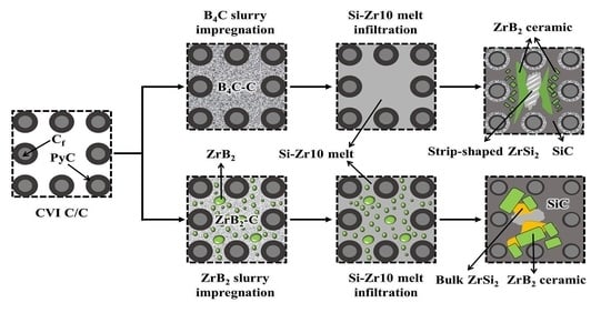
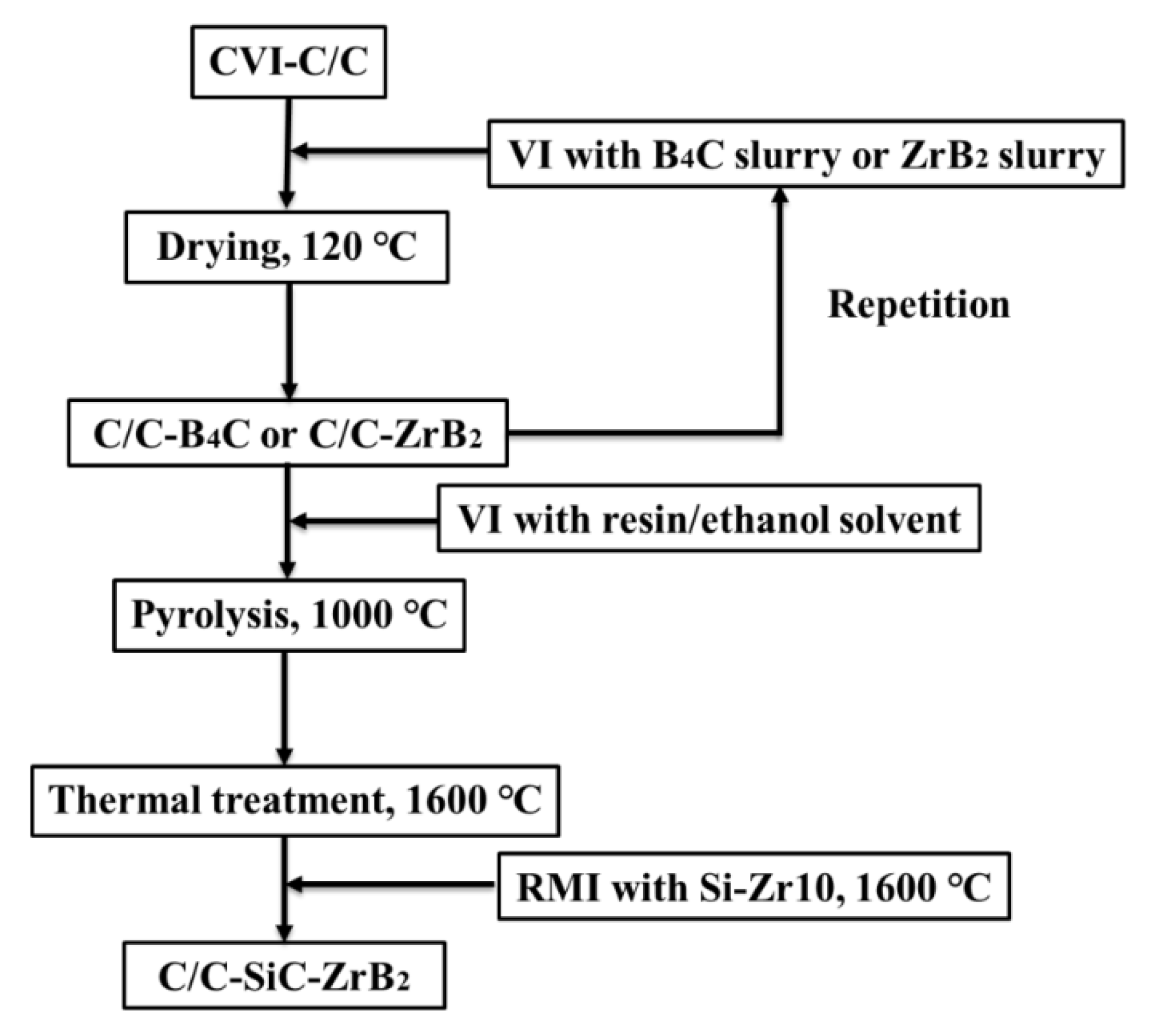
2. Materials and Methods

The fabrication procedure of C/C–SiC–ZrB2 composites is schematically shown in Figure 1. The density and fiber volume of two-dimensional porous CFC skeletons prepared by CVI are 0.90 g/cm3 and 17.6%, respectively. B4C and ZrB2 aqueous slurries were prepared as follows: the dispersant was firstly dissolved in deionized water, then B4C powder (average particle size: 0.5 μm, purity: 99.5%; Bike Nano Technology Company, Shanghai, China) and ZrB2 powder (average particle size: 0.7 μm, purity: 98.0%; China New Metal Materials Technology Co., Ltd, Beijing, China) were added into the dispersant solution, followed by planetary ball milling with ZrO2 balls for 10 h. Subsequently, CFC skeletons were vacuum impregnated (VI) with B4C slurry or ZrB2 slurry, and dried at 120 °C. After repeating the above infiltration steps for three and seven cycles, C/C–B4C and C/C–ZrB2 preforms were obtained. Then, these two preforms were infiltrated by phenolic resin (THC-800, purity: 95.0%; Shaanxi Taihang Fire Retardant Polymer Co., Ltd., Xi’an, China) ethanol solution to supply carbon source and fix the boride particles, followed by pyrolysis at 1000 °C and thermal treatment at 1600 °C. Finally, C/C–SiC–ZrB2 composites were produced in a vacuum furnace by infiltrating Si–Zr10 melt into the preforms at 1600 °C for 1 h. Here, the composite obtained from the C/C–B4C preform is marked as B4C-composite, and the other is marked as ZrB2-composite.
The density and open porosity were measured by Archimedes’ method. The phase compositions were characterized by using X-ray diffraction (XRD, mode: X’ PERT PRO MPD, PANalytical B.V., Holland) from 5° to 90° (2θ) with Cu Kα radiation (λ = 1.54 Å, 40 KV, 40 mA). The phase volume fractions of the composites were estimated by X-ray fluorescence (XRF, mode: Axios, PANalytical B.V., Almelo, Holland) of oxidized samples. The microstructures of different specimens were analyzed by scanning electron microscopy (SEM, mode: JSM-7001F, JEOL, Tokyo, Japan) and the elemental analysis was conducted by energy dispersive spectroscopy (EDS, mode: INCA X-MAX, Oxford Instruments, Abingdon, UK). The size distributions of ceramic particles were obtained from SEM images. At least 100 congener particles were selected from random areas to reduce the error of statistical analysis. The flexural strength of the samples with a dimension of 40.0 mm × 4.2 mm × 3.2 mm was measured by a three-bending test on universal testing machine (MTS, Mechanical Testing & Simulation, Eden Prairie, MN, USA), with a span of 30.0 mm and a loading rate of 0.5 mm/min.

3. Results and Discussion

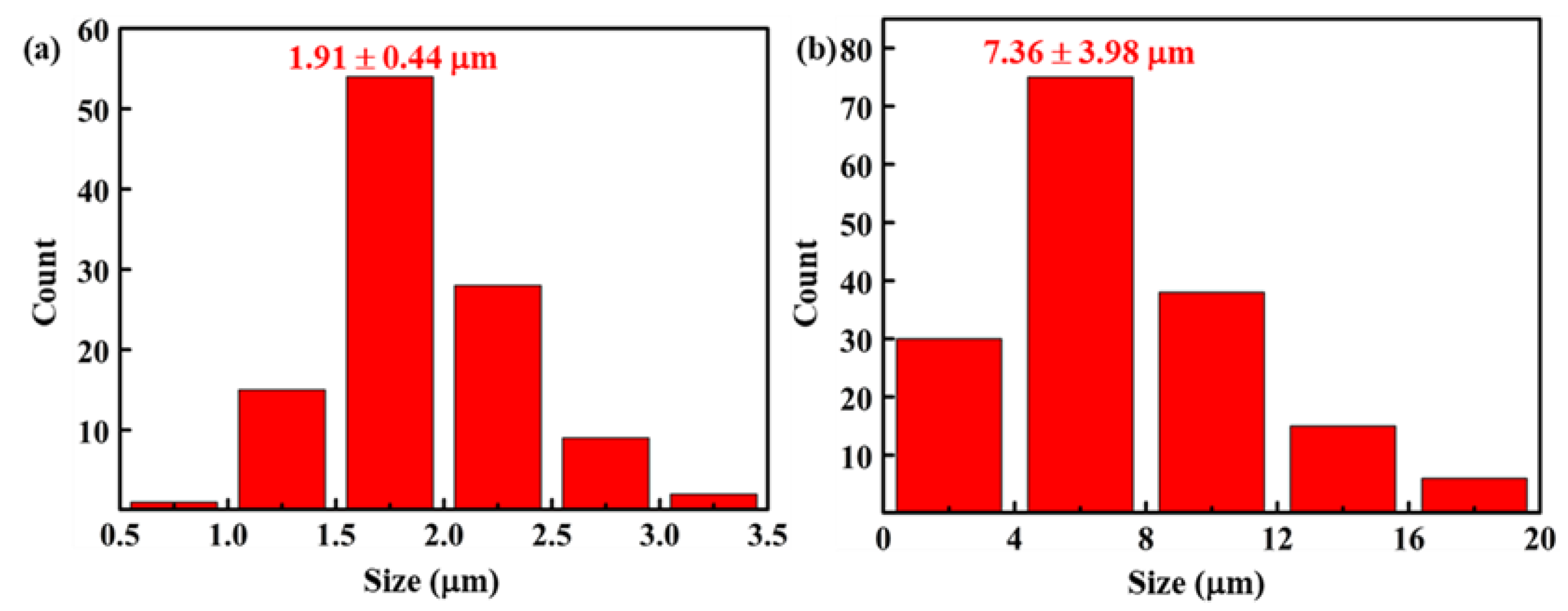
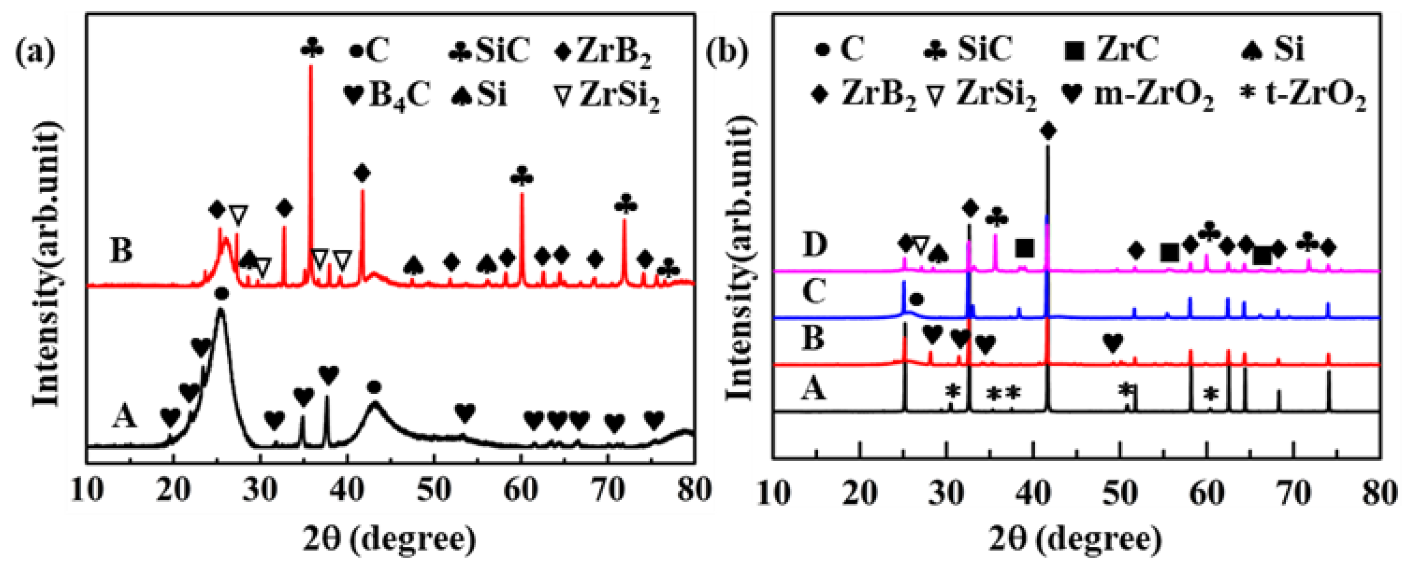
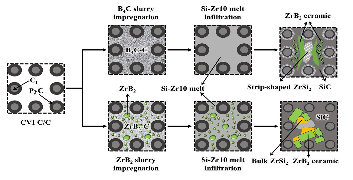
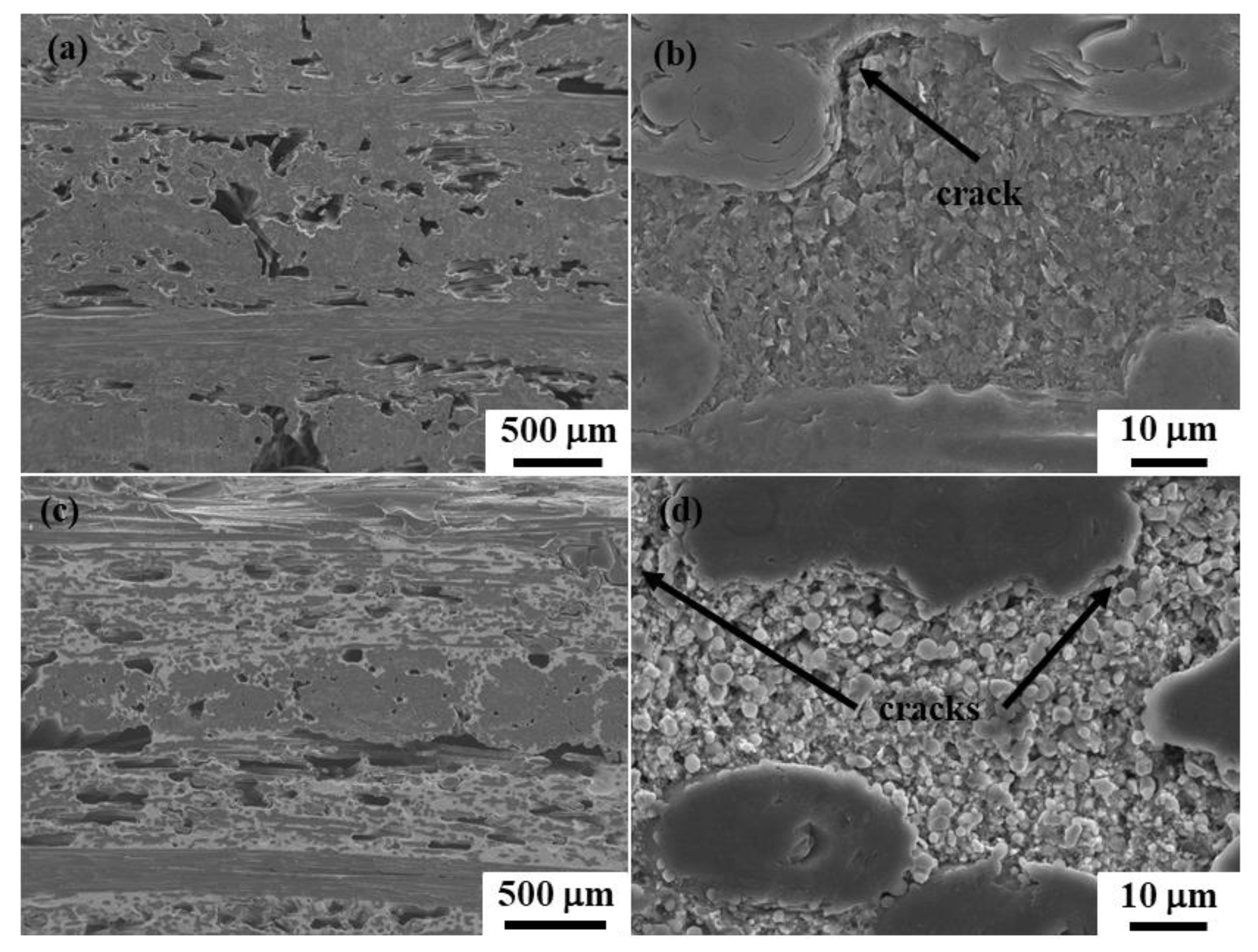
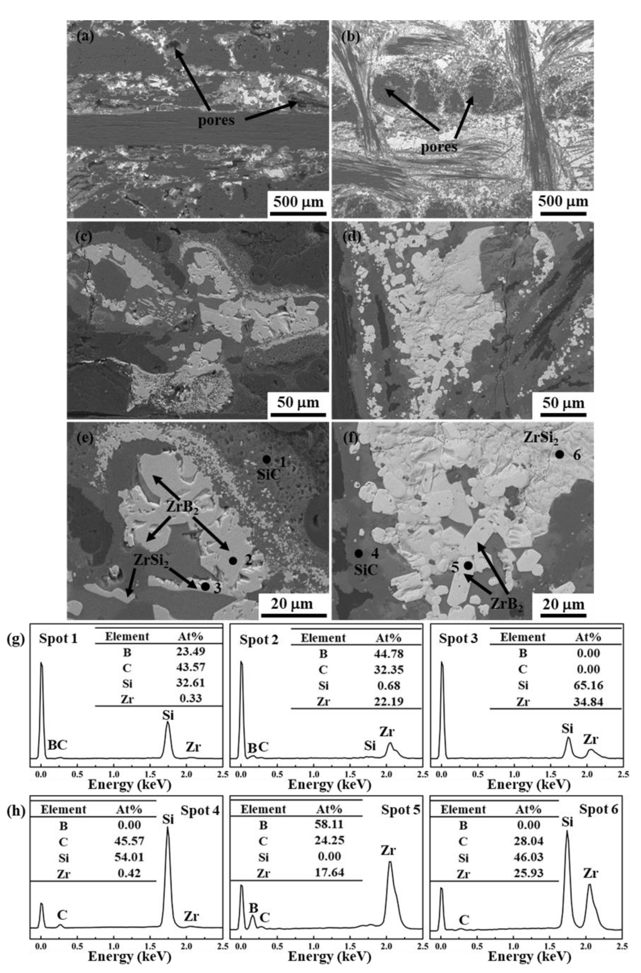
3.1. Microstructural Characterization of the C/C–SiC–ZrB2 Composites

The properties of the C/C–B4C and C/C–ZrB2 preforms are listed in Table 1. Owing to the lower density of B4C (2.52 g/cm3) when compared with ZrB2 (6.1 g/cm3), the B4C slurry, with the same mass fraction as the ZrB2 slurry, has relatively higher viscosity and larger flow resistance. Thus, the C/C–B4C preform, with similar open porosity to the C/C–ZrB2 preform, can be achieved after fewer cycles of B4C slurry infiltration. Figure 2 displays the SEM images for the polished cross-sections of these two preforms. As shown in Figure 2a,c, both preforms show similar microstructures, and there are many scattered pores between the fiber bundles. The gaps in the concentrated areas of the fiber bundles are occupied by pyrolytic carbon layers with a thickness of ~6 μm, while the voids among the loose areas of the fiber bundles are filled with a B4C–C or ZrB2–C mixture. In addition, the micro-cracks observed in the B4C–C and ZrB2–C mixtures can provide infiltration channels for the Si–Zr10 alloy (Figure 2b,d).
As demonstrated in Table 1, after infiltrating the Si–Zr10 alloy into the porous preforms, the density and open porosity of the as-fabricated B4C-composite are 1.98 g/cm3 and 18.04%, respectively, while those of the ZrB2-composite are 2.82 g/cm3 and 3.43%, respectively. The cross-sectional morphologies and detailed microstructures of the C/C–SiC–ZrB2 composites are shown in Figure 3. The B4C-composite shows a loose and porous structure, which is consistent with its low density (Figure 3a). The reasons for the loose structure of the B4C-composite can be mainly concluded in the following two aspects: firstly, it is easy to form a dense B4C layer near the surface of the C/C–B4C preform during the SI process, on account of the higher solid content of the slurry; secondly, the SiC–ZrB2 matrix formation reaction from the Si–Zr10 melt and B4C–C is intensely exothermic, and the thermal expansion coefficients of ZrB2 (6.2 × 10⁻⁶ K−1) and SiC (4 × 10⁻⁶ K−1) are higher than that of carbon (2–4 × 10⁻⁶ K−1) [24,25]. The volume expansion caused by in situ generated SiC–ZrB2 ceramics may further reduce, or even block, the infiltration channels of the melt. To further investigate the microstructure of B4C-composite, EDS analysis was carried out at the compact region between the fiber bundles (Figure 3c,e,g). There is only a continuous SiC layer near the B4C–C mixture, and some isolated ZrB2 particles, less than 1 µm, are dispersed in the SiC ceramic, far away from the SiC layer. When close to the center of the matrix, tens of micron-sized irregular ZrB2 particles are connected into a monolithic ZrB2 ceramic, which suggests that the distributions of in situ synthesized SiC and ZrB2 are not uniform at a micro-scale level. Moreover, there are strip-shaped residual alloys with a composition that is close to ZrSi2 in the center of the matrix.
In contrast, the ZrB2-composite presents a denser microstructure, where several closed micro-pores can only be observed in intra-bundle regions (Figure 3b). According to EDS analysis (Figure 3f), the matrix in the ZrB2-composite mainly consists of a continuous grey SiC phase, a white plate-like ZrB2 phase, and a rough white bulk ZrSi2 phase. Figure 3d further shows that the ZrB2–C mixture successfully transforms into a SiC–ZrB2 matrix after the RMI process. Compared with the B4C-composite, a continuous SiC layer is also formed closest to the carbon matrix in the ZrB2-composite, and plate-like ZrB2 ceramics are more scattered (Figure 3d). The voids between the plate-like ZrB2 particles are mostly filled with the generated SiC ceramic. Besides that, the bulk ZrSi2 alloy is distributed along the region that is rich in ZrB2 (Figure 3f). Figure 2d and Figure 3f further show that, after infiltration, the number of ZrB2 particles declines, but the size of them increases significantly. The particle size distributions of ZrB2 powder in the C/C–ZrB2 preform and ZrB2-composite are shown in Figure 4. On the whole, ZrB2 in the preform is near-spherical, and the average size of larger particles is about 1.91 ± 0.44 μm (Figure 2d and Figure 4a), while, after RMI, most of them grow into elongated plate-like particles with an average size of 7.36 ± 3.98 μm in the long axis direction (Figure 3f and Figure 4b).
Figure 5 displays the XRD patterns of the C/C–B4C and C/C–ZrB2 preforms before and after the RMI process. The B4C-composite consists of SiC, ZrB2, residual ZrSi2 alloy, unreacted B4C, and amorphous C (Figure 5a). The result reveals that only the part of Zr in the Si–Zr10 alloy has been converted to ZrB2, by reacting with B4C, which conforms to the microscopic observation in Figure 3c and the low ZrB2 content (1.47%) in Table 1. The diffraction peaks of the ZrB2-composite mainly belong to the ZrB2 and SiC phases (Figure 5b). In addition, residual Si, the ZrSi2 phase, and a small amount of the ZrC phase are also detected. By analyzing the phase composition changes during the preparation procedure of the ZrB2-composite, it is found that during the pyrolysis and carbonization of the phenolic resin at 1000 °C, slightly oxidized initial ZrB2 particles are further oxidized to form m-ZrO2. Then, ZrO2 is turned into ZrC by carbothermal reduction with solid carbon in the process of heat treating at 1600 °C.

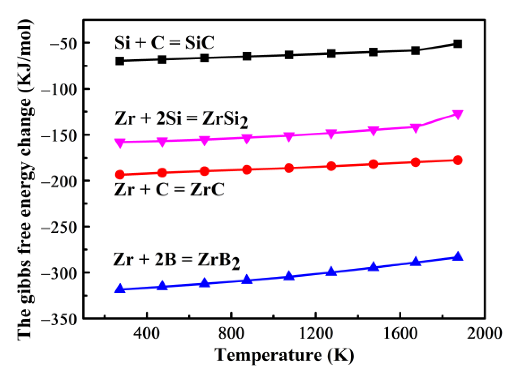
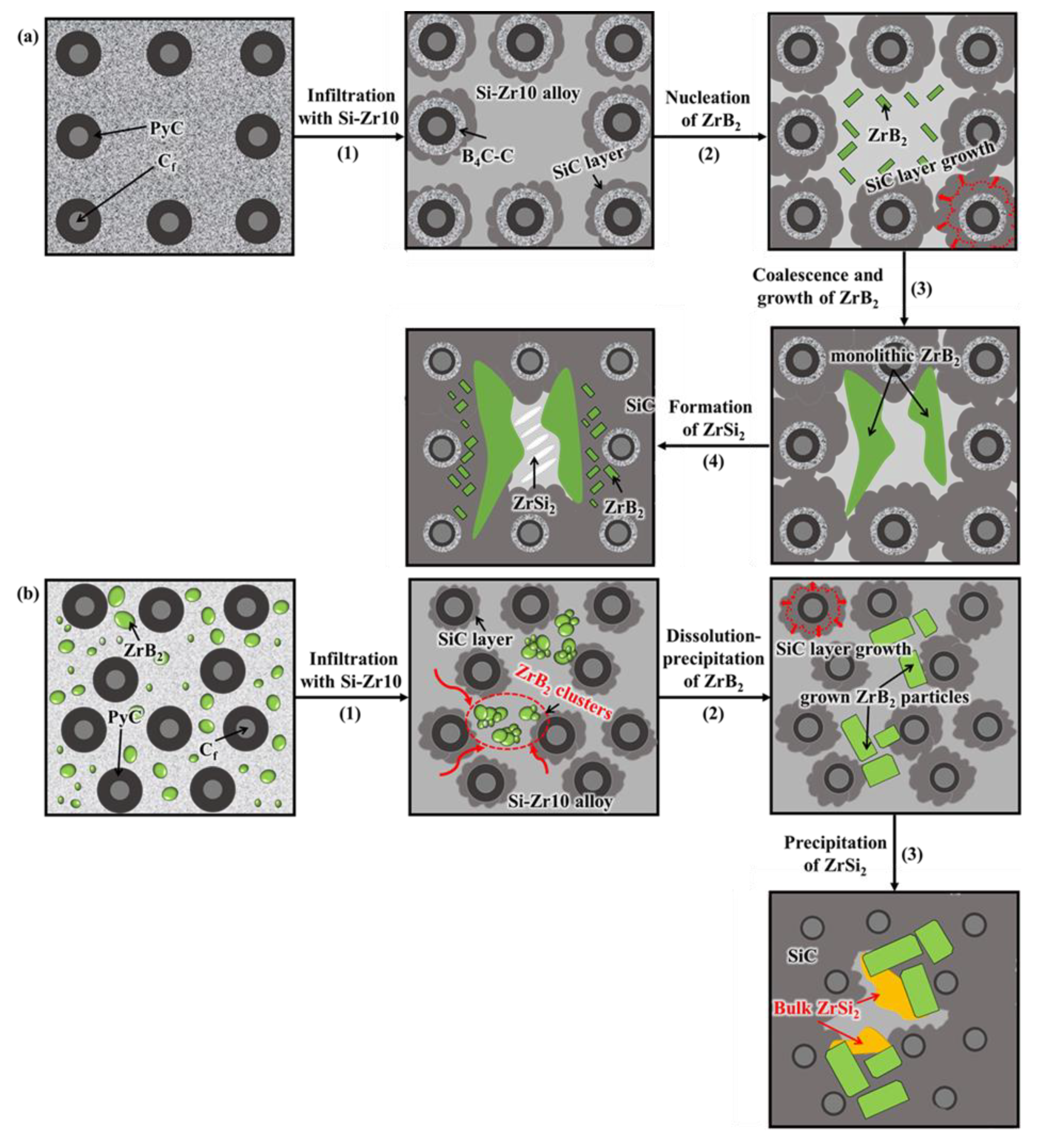
3.2. Microstructural Evolution and Formation Mechanism of the C/C–SiC–ZrB2 Composites

The target of preparing C/C–SiC–UHTC composites is to achieve a compact composite with a homogeneously distributed ceramic matrix and high UHTC content. Therefore, investigating the microstructural evolution and formation mechanism of C/C–SiC–ZrB2 composites is conducive to optimizing the preparation conditions and improving the performance of the composites. In this work, the fabrication of C/C–SiC–ZrB2 composites is mainly based on the following liquid–solid chemical reaction:
Si + C = SiC
Zr + C = ZrC
Zr + 2B = ZrB2
Zr + 2Si = ZrSi2
The Gibb’s free energy change of these reactions, calculated by thermodynamics in the standard state, is shown as a function of temperature in Figure 6, which proves that each reaction is thermodynamically feasible. On the basis of microstructural characterization of the composites, their reaction ability, and the phase diagrams among the Si–Zr–C–B system, the microstructural evolution and formation mechanism of the SiC–ZrB2 matrix is summarized in Figure 7.
As shown in Figure 7a, firstly, with the infiltration of molten Si–Zr10 into the C/C–B4C preform, by capillary force, C and B atoms in the B4C–C mixture dissolve into the alloy. Owing to the low Zr content in the Si–Zr10 eutectic alloy, the saturated solubility of C and B in the Si–Zr10 melt is close to that in pure Si melt. In terms of the Si–C and Si–B binary phase diagrams, the solubility of C is much lower than that of B in the Si melt at 1600 °C [26,27]. Thus, C atoms preferentially become saturated and react with enough Si, according to Equation (1), forming a continuous SiC layer. Then, the SiC layer separates the B4C–C mixture from the melt, and the further formed SiC–ZrB2 matrix is mainly controlled by the diffusion of C and B atoms through the layer [28]. Secondly, B atoms that can only be consumed by Zr atoms reach saturation. Figure 6 demonstrates that Equation (3) is more favorable than Equation (2) because of a more negative Gibb’s free energy change, revealing that Zr prefers to react with B to form ZrB2 via Equation (3). Therefore, the nucleation and precipitation of ZrB2 grains occur in the melt. Thirdly, along with the continuation of the RMI process, the ZrB2 grains coalesce and grow, forming a monolithic ZrB2 ceramic. Finally, during the cooling process, with the gradual decrease in the saturated solubility of C and B atoms, the SiC and ZrB2 ceramics further precipitate out, in which SiC is dominant because of a relatively higher Si content in the superfluous melt. Some ZrB2 grains cannot migrate to the surface of the monolithic ZrB2 ceramic in time, and become isolated particles in the SiC matrix [29]. In the areas far away from the B4C–C mixture, since C and B atoms have not diffused out, strip-shaped ZrSi2 is generated via Equation (4) and separates out from the superfluous melt. Therefore, it can be concluded that the uneven SiC–ZrB2 distribution in the B4C-composite is primarily due to the asynchronous generation of SiC and ZrB2 ceramics. In addition, the incomplete transformation from a Si–Zr10 alloy to a SiC–ZrB2 matrix is attributed to the low diffusion coefficients of B and C atoms through the SiC layer.
Correspondingly, the structural evolution mechanism of the ZrB2-composite is shown in Figure 7b. First, after infiltrating the molten Si–Zr10 alloy into the C/C–ZrB2 preform, C atoms dissolve and become saturated quickly. A continuous layer, rich in SiC ceramic, is preferentially formed via Equation (1) because of the much higher Si content in the Si–Zr10 alloy. After that, the ZrB2 particles, without the fixation of resin carbon, are rearranged and aggregated together to form larger clusters under the surface tension of the melt. As a previous study reported, ZrB2 has highly covalent bonding and a low self-diffusion coefficient [30]. However, the liquid alloy between ZrB2 particles with inhomogeneous sizes can accelerate mass transportation and facilitate grain boundary migration [31]. In addition, based on the phase diagrams of the Si–B and Si–Zr systems, B and Zr atoms have certain solubility in liquid Si [27,32]. Considering the above four factors, the particles in ZrB2 clusters grow through the dissolution–diffusion–precipitation mechanism. The small particles in each ZrB2 aggregation dissolve and diffuse through the melt, then crystallize on the surface of large particles, leaving irregular gaps between the grown ZrB2 particles. Moreover, previous studies have noted that the preferential growth directions of ZrB2 grains are [210] and [110], which leads to the plate-shaped morphology of the grown ZrB2 grains [33,34]. As the RMI process continues, a large amount of Si is consumed through Equation (1), and the composition of the melt shifts to hypereutectic, according to the Si–Zr phase diagram [32]. Meanwhile, the solid ZrSi2 phase precipitates out from hypereutectic melt near the ZrB2-rich areas due to the compatibility of the ZrB2 and Zr elements. In summary, the introduction of ZrB2 particles has no visible effect on the reaction process of infiltrating the Si–Zr10 alloy into CFC preforms. With the progress of infiltration, the composition of the Si–Zr10 eutectic alloy changes to hypereutectic, and bulk solid ZrSi2 precipitates out. Besides that, the melt can accelerate the growth of ZrB2 particles, which reduces the distribution uniformity of ZrB2 ceramic in ZrB2-composites.

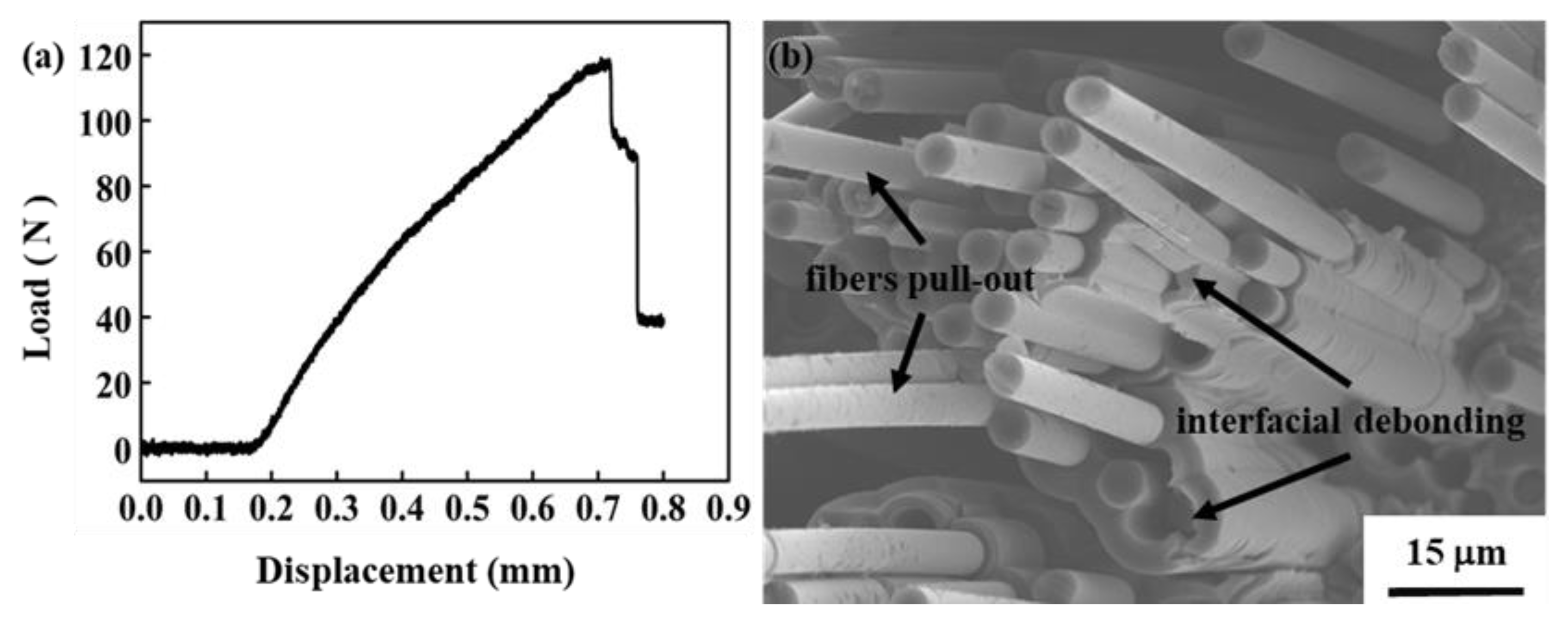
3.3. Mechanical Properties of C/C–SiC–ZrB2 Composite

According to a previous study on carbon fiber-reinforced ceramic matrix composites with the same fiber volume, the density of composites will be reduced with an increase in porosity, which leads to a sharp decrease in mechanical strength [35]. The ZrB2-composite is believed to show better mechanical properties because it displays a denser matrix, along with much lower open porosity (3.43%) and much higher density (2.82 g/cm3). Here, the mechanical property of the as-fabricated ZrB2-composite was investigated by three-point bending tests. The flexural load–displacement curve and fracture surface micrograph are shown in Figure 8. The curve shows a step-like decline after reaching the maximum value (Figure 8a), proving that the ZrB2-composite exhibits pseudo-plastic fracture behavior. The bending strength and elastic modulus are calculated to be 115.67 ± 8.85 MPa and 12.40 ± 1.90 GPa, respectively. Moreover, long fibers pull out and obvious interfacial debonding can be observed in Figure 8b, and the surface of the pulled-out fibers is relatively smooth, illustrating that most of the carbon fibers are not evidently eroded by the melt during the RMI process.

4. Conclusions

In summary, the C/C–SiC–ZrB2 composites have been successfully fabricated by a combined process of SI and RMI through a Si–Zr10 eutectic alloy infiltration and chemical reaction at 1600 °C. Two preforms of C/C–B4C and C/C–ZrB2, with similar open porosities, were prepared through the SI process. Importantly, the effects of B4C and ZrB2 particles on the microstructural evolution and formation mechanism of C/C–SiC–ZrB2 composites during RMI were explored. In the B4C-composite, the ZrB2 grains formed via the reaction from B4C particles and the Si–Zr10 melt coalesced together, and generated a monolithic ZrB2 ceramic, which led to heterogeneous distribution of the SiC and ZrB2 ceramics. In the ZrB2-composite, the ZrB2 particles were aggregated together to form clusters under the surface tension of the melt, and then grown into elongated plate-like particles through the dissolution–diffusion–precipitation mechanism. Compared with the B4C-composite, the ZrB2-composite had a higher ZrB2 content (9.51%), higher density (2.82 g/cm3), and lower open porosity (3.43%). Moreover, the ZrB2-composite also exhibited pseudo-plastic fracture behavior, and most of the carbon fibers were not evidently eroded by the melt. Regrettably, resulting from the dissolution of resin carbon, the aggregation and growth of the ZrB2 particles reduced the dispersion uniformity of the ZrB2 ceramic in the ZrB2-composite. This work not only provides a low-cost and relatively low-temperature strategy to fabricate C/C–SiC–ZrB2 composites with a higher ZrB2 content, through Si–Zr alloy infiltration, but also offers new insights into the effects of different boride particles on the liquid–solid reaction mechanism during the RMI process.

Author Contributions

Conceptualization, W.Z.; methodology, W.Z. and C.H.; validation, Q.S. and H.Z.; formal analysis, Q.S.; investigation, Q.S. and H.Z.; resources, C.H.; writing—original draft preparation, Q.S.; writing—review and editing, W.Z. and C.H.; project administration, W.Z. and C.H.; funding acquisition, W.Z. All authors have read and agreed to the published version of the manuscript.

Funding

This research was funded by Innovation Academy for Green Manufacture (Grant No. IAGM2020C22) and Key Laboratory of Multi-phase Complex Systems (Grant No. MPCS-2021-A-02), Chinese Academy of Sciences.

Conflicts of Interest

The authors declare no conflict of interest.

References

  1. Fitzer, E. The future of carbon-carbon composites. Carbon 1987, 25, 163–190. [Google Scholar] [CrossRef]
  2. Windhorst, T.; Blount, G. Carbon-carbon composites: A summary of recent developments and applications. Mater. Des. 1997, 18, 11–15. [Google Scholar] [CrossRef]
  3. Li, T.; Yang, Z.; Qiao, S.; Zheng, X. High temperature oxidation resistance improvement of carbon-carbon composite. Carbon 1993, 31, 1361–1363. [Google Scholar] [CrossRef]
  4. Liu, L.; Li, H.J.; Feng, W.; Shi, X.H.; Li, K.Z.; Guo, L.J. Ablation in different heat fluxes of C/C composites modified by ZrB2–ZrC and ZrB2–ZrC–SiC particles. Corros. Sci. 2013, 74, 159–167. [Google Scholar] [CrossRef]
  5. Jin, X.C.; Fan, X.L.; Lu, C.S.; Wang, T.J. Advances in oxidation and ablation resistance of high and ultra-high temperature ceramics modified or coated carbon/carbon composites. J. Eur. Ceram. Soc. 2018, 38, 1–28. [Google Scholar] [CrossRef]
  6. Arai, Y.; Inoue, R.; Goto, K.; Kogo, Y. Carbon fiber reinforced ultra-high temperature ceramic matrix composites: A review. Ceram. Int. 2019, 45, 14481–14489. [Google Scholar] [CrossRef]
  7. Li, Q.G.; Dong, S.M.; Wang, Z.; He, P.; Zhou, H.J.; Yang, J.S.; Wu, B.; Hu, J.B. Fabrication and properties of 3D Cf/SiC–ZrC composites, using ZrC precursor and polycarbosilane. J. Am. Ceram. Soc. 2012, 95, 1216–1219. [Google Scholar] [CrossRef]
  8. Zhou, H.J.; Ni, D.W.; He, P.; Yang, J.S.; Hu, J.B.; Dong, S.M. Ablation behavior of C/C-ZrC and C/SiC-ZrC composites fabricated by a joint process of slurry impregnation and chemical vapor infiltration. Ceram. Int. 2018, 44, 4777–4782. [Google Scholar] [CrossRef]
  9. Tang, S.F.; Deng, J.Y.; Wang, S.J.; Liu, W.C. Fabrication and characterization of an ultra-high-temperature carbon fiber-reinforced ZrB2–SiC matrix composite. J. Am. Ceram. Soc. 2007, 90, 3320–3322. [Google Scholar] [CrossRef]
  10. Wang, Y.G.; Zhu, X.J.; Zhang, L.T.; Cheng, L.F. C/C-SiC-ZrC composites fabricated by reactive melt infiltration with Si0.87Zr0.13 alloy. Ceram. Int. 2012, 38, 4337–4343. [Google Scholar] [CrossRef]
  11. Tang, S.F.; Hu, C.L. Design, preparation and properties of carbon fiber reinforced ultra-high temperature ceramic composites for aerospace applications: A review. J. Mater. Sci. Technol. 2017, 33, 117–130. [Google Scholar] [CrossRef]
  12. Jiang, S.Z.; Xiang, X.; Chen, Z.K.; Xiao, P.; Huang, B.Y. Influence factors of C/C–SiC dual matrix composites prepared by reactive melt infiltration. Mater. Des. 2009, 30, 3738–3742. [Google Scholar] [CrossRef]
  13. Zhong, Q.; Zhang, X.Y.; Dong, S.M.; Yang, J.S.; Hu, J.B.; Gao, L.; He, P.; Zhou, H.J.; Wang, Z.; Ding, Y.S. Reactive melt infiltrated Cf/SiC composites with robust matrix derived from novel engineered pyrolytic carbon structure. Ceram. Int. 2017, 43, 5832–5836. [Google Scholar] [CrossRef]
  14. Guo, W.J.; Ye, Y.C.; Bai, S.X.; Zhu, L.A.; Li, S. Preparation and formation mechanism of C/C-SiC composites using polymer-Si slurry reactive melt infiltration. Ceram. Int. 2020, 46, 5586–5593. [Google Scholar] [CrossRef]
  15. Zou, L.; Wali, N.; Yang, J.M.; Bansal, N.P.; Dong, Y. Microstructural characterization of a Cf/ZrC composite manufactured by reactive melt infiltration. Int. J. Appl. Ceram. Technol. 2011, 8, 329–341. [Google Scholar] [CrossRef]
  16. Chen, S.A.; Zhang, C.R.; Zhang, Y.D.; Hu, H.F. Influence of pyrocarbon amount in C/C preform on the microstructure and properties of C/ZrC composites prepared via reactive melt infiltration. Mater. Des. 2014, 58, 570–576. [Google Scholar] [CrossRef]
  17. Ju, L.; Lenosky, T.J. Thermochemical and mechanical stabilities of the oxide scale of ZrB2+SiC and oxygen transport mechanisms. J. Am. Ceram. Soc. 2008, 91, 1475–1480. [Google Scholar] [CrossRef]
  18. Tong, Y.G.; Bai, S.X.; Zhang, H.; Chen, K. C/C–SiC composite prepared by Si–10Zr alloyed melt infiltration. Ceram. Int. 2012, 38, 3301–3307. [Google Scholar] [CrossRef]
  19. Tong, Y.G.; Bai, S.X.; Qin, Q.H.; Zhang, H.; Ye, Y.C. Effect of infiltration time on the microstructure and mechanical properties of C/C-SiC composite prepared by Si-Zr10 alloyed melt infiltration. Ceram. Int. 2015, 41, 4014–4020. [Google Scholar] [CrossRef]
  20. Tong, Y.G.; Cai, Z.H.; Bai, S.X.; Hua, M.Y.; Xie, W.; Ye, Y.C.; Li, Y. Microstructures and properties of Si-Zr alloy based CMCs reinforced by various porous C/C performs. Ceram. Int. 2018, 44, 16577–16582. [Google Scholar] [CrossRef]
  21. Chen, X.W.; Feng, Q.; Kan, Y.M.; Ni, D.W.; Zhou, H.J.; Gao, L.; Zhang, X.Y.; Ding, Y.S.; Dong, S.M. Effects of preform pore structure on infiltration kinetics and microstructure evolution of RMI-derived Cf/ZrC-ZrB2-SiC composite. J. Eur. Ceram. Soc. 2020, 40, 2683–2690. [Google Scholar] [CrossRef]
  22. Ni, D.W.; Wang, J.X.; Dong, S.M.; Chen, X.W.; Kan, Y.M.; Zhou, H.J.; Gao, L.; Zhang, X.Y. Fabrication and properties of Cf/ZrC-SiC-based composites by an improved reactive melt infiltration. J. Am. Ceram. Soc. 2018, 101, 3253–3258. [Google Scholar] [CrossRef]
  23. Chiang, Y.-M.; Messner, R.P.; Terwilliger, C.D.; Behrendt, D.R. Reaction-formed silicon carbide. Mater. Sci. Eng. A 1991, 144, 63–74. [Google Scholar] [CrossRef]
  24. Baxter, R.I.; Rawlings, R.D.; Iwashita, N.; Sawada, Y. Effect of chemical vapor infiltration on erosion and thermal properties of porous carbon/carbon composite thermal insulation. Carbon 2000, 38, 441–449. [Google Scholar] [CrossRef]
  25. Fahrenholtz, W.G.; Hilmas, G.E.; Talmy, I.G.; Zaykoski, J.A. Refractory biborides of zirconium and hafnium. J. Am. Ceram. Soc. 2007, 90, 1347–1364. [Google Scholar] [CrossRef]
  26. Durand, F.; Duby, J.C. Carbon solubility in solid and liquid silicon—A review with reference to eutectic equilibrium. J. Phase Equilib. 1999, 20, 61–63. [Google Scholar] [CrossRef]
  27. Ikhmayies, S.J. Thermo-calc determination of phase diagram of Si-B binary system. JOM 2021, 73, 253–259. [Google Scholar] [CrossRef]
  28. Zou, L.H.; Wali, N.; Yang, J.-M.; Bansal, N.P. Microstructural development of a Cf/ZrC composite manufactured by reactive melt infiltration. J. Eur. Ceram. Soc. 2010, 30, 1527–1535. [Google Scholar] [CrossRef]
  29. Wang, D.K.; Dong, S.M.; Zhou, H.J.; Zhang, X.Y.; Ding, Y.S.; Zhu, G.X. Fabrication and microstructure of 3D Cf/ZrC-SiC composites: Through RMI method with ZrO2 powders as pore-making agent. Ceram. Int. 2016, 42, 6720–6727. [Google Scholar] [CrossRef]
  30. Sonber, J.K.; Suri, A.K. Synthesis and consolidation of zirconium diboride: Review. Adv. Appl. Ceram. 2011, 11, 321–334. [Google Scholar] [CrossRef]
  31. Monteverde, F.; Bellosi, A.; Guicciardi, S. Processing and properties of zirconium diboride-based composites. J. Eur. Ceram. Soc. 2002, 22, 279–288. [Google Scholar] [CrossRef]
  32. Bulanova, M.; Firstov, S.; Gornaya, I.; Miracle, D. The melting diagram of the Ti-corner of the Ti–Zr–Si system and mechanical properties of as-cast compositions. J. Alloys Compd. 2004, 384, 106–114. [Google Scholar] [CrossRef]
  33. Otani, S.; Ishizawa, Y. Preparation of ZrB2 single crystals by the floating zone method. J. Cryst. Growth 1996, 165, 319–322. [Google Scholar] [CrossRef]
  34. Ji, Z.; Sun, S.K.; Zhang, G.J.; Kan, Y.M.; Wang, P.L.; Ohji, T. Chemical reactions, anisotropic grain growth and sintering mechanisms of self-reinforced ZrB2–SiC doped with WC. J. Am. Ceram. Soc. 2011, 94, 1575–1583. [Google Scholar] [CrossRef]
  35. Xu, Y.; Zhang, L.; Cheng, L.; Yan, D. Microstructure and mechanical properties of three-dimensional carbon/silicon carbide composites fabricated by chemical vapor infiltration. Carbon 1998, 36, 1051–1056. [Google Scholar] [CrossRef]
Figure 1. The fabrication procedure of C/C–SiC–ZrB2 composites.
Crystals 11 01352 g001
Figure 2. SEM images of several used preforms: polished cross-sections of porous C/C–B4C (a) and C/C–ZrB2 preforms (c); the B4C–C (b) and ZrB2–C mixture (d) between carbon fibers.
Crystals 11 01352 g002
Figure 3. Back-scattering images and EDS analysis for polished cross-sections of C/C–SiC–ZrB2 composites: (a,c,e,g) B4C-composite; (b,d,f,h) ZrB2-composite.
Crystals 11 01352 g003
Figure 4. The particle size distributions of ZrB2: (a) C/C–ZrB2 preform; (b) ZrB2-composite.
Crystals 11 01352 g004
Figure 5. XRD patterns of different preforms and composites: (a) A, C/C–B4C preform; B, B4C-composite; (b) A, initial ZrB2 particles; B, C/C–ZrB2 preform after pyrolysis at 1000 °C; C, C/C–ZrB2 preform after heat treating at 1600 °C; D, ZrB2-composite.
Crystals 11 01352 g005
Figure 6. The Gibb’s free energy change as a function of temperature for the reaction involved in this work.
Crystals 11 01352 g006
Figure 7. Schematic illustrations of microstructural evolution and formation mechanism for C/C–SiC–ZrB2 composites during the RMI process: (a) B4C-composite; (b) ZrB2-composite.
Crystals 11 01352 g007
Figure 8. (a) Load–displacement curve of the ZrB2-composites; (b) microstructure of fracture surface.
Crystals 11 01352 g008
Table 1. Properties of C/C–B4C and C/C–ZrB2 preforms before and after reactive melt infiltration (RMI).
SamplesDensity (g/cm3)Open Porosity (%)Phase Volume Fraction (%)
CfZrB2B4CZrSi2SiC
C/C-B4C1.2732.0717.60N/A6.74N/AN/A
C/C-ZrB21.5834.7517.609.51N/AN/AN/A
B4C-composite1.9818.0417.601.475.872.4523.10
ZrB2-composite2.823.4317.609.51N/A4.2638.67
Publisher’s Note: MDPI stays neutral with regard to jurisdictional claims in published maps and institutional affiliations.

