Article

Preparation of Superhydrophobic Surfaces Based on Rod-Shaped Micro-Structure Induced by Nanosecond Laser

1
Luoyang Ship Material Research Institute, Luoyang 471039, China
2
Department of Mechanical Engineering, Tsinghua University, Beijing 100084, China
*
Author to whom correspondence should be addressed.
Crystals 2021, 11(11), 1274; https://doi.org/10.3390/cryst11111274
Submission received: 31 August 2021 / Revised: 18 September 2021 / Accepted: 16 October 2021 / Published: 20 October 2021
(This article belongs to the Special Issue Non-traditional Machining of Crystal Materials)

Abstract

:
Solid–liquid frictional resistance is mainly attributed to the adhesion caused by the boundary layer effect. Superhydrophobic surfaces are expected to be an effective method to reduce frictional resistance. In this paper, a rod-shaped micro-structure was prepared on surfaces of Al alloy (5083) and Ti alloy (TC4) by line-by-line scanning with nanosecond laser. The inherent properties of the metal materials—such as their coefficient of thermal conductivity (CTC) and specific heat capacity (SHC)—had a major influence on the surface morphology and shape size of the rod-shaped micro-structure. Both two metals showed apparent oxidation on their surfaces during laser ablation, however, the degree of surface oxidation of the Al alloy was greater than that of the Ti alloy due to its more fragmentary rod-shaped micro-structure. The laser-treated surfaces could turn from hydrophilic to hydrophobic or even superhydrophobic after being left in the air for 20 days, which might be caused by the adsorption of low-surface energy matter in the air. In addition, the contact angle of the Al alloy was larger than that of the Ti alloy, which is due to the larger ratio of height to width of the micro–nano composite rod-shaped micro-structure on the surface of the Al alloy.

1. Introduction

Underwater operation equipment, such as underwater robots, underwater unmanned vehicles, and towed sonar, would be subjected to great resistance in the process of navigation, resulting in a decrease in navigation efficiency and an increase in energy consumption. This is mainly attributed to the adhesion of water to the metal surface caused by the boundary layer effect [1,2]. According to previous research, the frictional resistance caused by water adhesion can account up to 80–85% of the total resistance [3]. It is therefore necessary to study how to reduce the frictional resistance of the surface. At the same time, because the overall weight of the equipment is limited by energy, lightweight alloys, such as aluminum alloys and titanium alloys, have a wider range of application in underwater operation equipment than other metal materials. In order to reduce navigation resistance, improve navigation efficiency, and reduce energy waste, it is necessary to study the advanced surface drag reduction technology of underwater operation equipment.
In recent years, some methods for reducing the drag of underwater vehicles have been proposed such as surface coating [4], microbubble technology [5], shape optimization design [6], and the micro-texture method. However, limited by the cost, complexity, and efficiency of drag reduction, these methods still could not meet the actual requirements. Recently, many special functions caused by unique micro–nano structures have been found in natural biological surfaces: for example, water droplets can roll on the surfaces of lotus leaves [7], colorful pigmentation of butterflies [8], and the fact that a water strider can walk freely on the surface of the water [9]. Inspired by the lotus leaf, bionic drag reduction based on surface micro–nano structure is expected to be a new and effective method which has attracted significant attention from many researchers. A large number of micro-convex structures are diffusely distributed on the surface of the lotus leaf, and countless particle structures are also scattered on these convex structures. The ordered micro–nano composite structure reduces the contact area between droplets and the surface and improves the hydrophobic effect. Therefore, it is very necessary to construct the surface micro–nano structure that can enhance hydrophobicity.
With the progress of micro–nano fabrication technology, many methods have been used to prepare surface micro–nano structures, such as lithography [10], sol–gel coating [11], electrochemical deposition [12], and chemical etching [13]. Compared with these methods, laser direct writing technology has the advantages of low cost, a simple step-by-step procedure, high efficiency, environmental friendliness, and great material adaptability [14,15,16,17]. Many researchers have implemented wetting modification using short pulse laser by fabricating a micro–nano structure on the surfaces of polydimethylsiloxane [18], silicon [19], and metal [20,21]. Moreover, laser can also change the chemical composition while fabricating the surface micro–nano structure. For example, Boinovich et al. [22] found that the chemical composition transformation caused by laser treatment combined with the superhydrophobic state endows the surface with better chemical and mechanical properties. The key of the laser preparation of surface micro–nano structures is the interaction between light and material. When the nanosecond laser is focused on the surface of the material, the energy of the laser becomes the heat absorbed by the material. The material quickly heats up and melts to form a molten pool. After the laser is removed, the melted material is cooled and solidified again to form a random micro–nano structure. Therefore, the nature of the material has an important influence on the process of the laser fabrication of a micro–nano structure [23]. However, there are a few studies on the influence of the intrinsic properties of the material on the preparation of a micro–nano structure by laser. There are even fewer studies that directly compare the formation of micro–nano structures with two materials. The difference in the wettability of micro–nano structures prepared on the surfaces of different materials with the same laser parameters also needs further study.
In this paper, a micro–nano structure was prepared on the surfaces of aluminum alloy (5083) and titanium alloy (TC4) by laser direct writing. The surface morphologies of these two kinds of materials after laser processing were studied, and the influence of their intrinsic properties on the surface micro–nano structure was analyzed. The superhydrophobic surface was obtained after laser processing and a period of storage. The chemical composition and changes in initial surface, laser-treated surface, and superhydrophobic surface were investigated. The surface roughness and micro-morphological parameters were statistically analyzed and their effects on surface wettability were discussed. This work visually demonstrates the difference between the effects of laser treatment on the morphology and wettability transition of aluminum alloys and titanium alloys, and has certain positive significance for the laser preparation of superhydrophobic metal surfaces.

2. Experiment

2.1. Materials and Pretreatment

Commercial titanium alloy (TC4) and aluminum alloy (5083) (Hongwang Mould Co., Ltd., Shenzhen, China) were used as the substrate materials in this experiment. The metal sheets with a thickness of 2 mm were cut into 20 mm × 20 mm by wire cutting. Before laser processing, the substrates were polished with sandpaper and then successively cleaned with acetone, anhydrous ethanol, and deionized water for 20 min by ultrasound. Then, the substrates were blow-dried with pure nitrogen for later use.

2.2. Fabrication of Superhydrophobic Surface

A fiber nanosecond laser (Huaray, Wuhan, China) with a wavelength of 1064 nm, pulse duration of 280 ns, and a beam spot diameter of 50 μm was used to irradiate the surface of dried substrates. The single pulse energy was set to approximately 50 μJ. The beam spot was accurately focused on the surface through a focusing lens (focal length = 135 mm) and the micro–nano structure was prepared by line-by-line scanning with a three-axis precision motion platform (Qianzhuotai, Dongguan, China). Furthermore, the laser repetition, scanning speed, and scanning interval were set to 120 kHz, 0.36 m/s, and 25 μm, respectively. The whole process of laser treatment was carried out in an air environment and at room temperature.

2.3. Surface Characterization

The surface morphology was observed by scanning electron microscope (SEM, Quanta 650, FEI, Hillsboro, OR, USA) and the chemical composition was investigated by energy dispersive spectroscopy (EDS, Genesis 2000, AMETEK, Philadelphia, PA, USA). The three-dimensional morphology and roughness parameters (including maximum peak height, maximum sag height, contour mean difference, ratio of height to width, and void volume) were measured by laser confocal microscopy (LCM, OLS5000, Olympus, Tokyo, Japan). The contact angle (CA) was measured by a contact angle measuring instrument (JC2000DM, Zhongyikexin, Beijing, China) with a droplet volume of 5 μL. The sessile drop method and Laplace fitting method were used in the measurement at room temperature. The contact angle of the same sample was measured 6 times at different positions and the average value was taken.

3. Results and Discussions

Figure 1 shows the SEM images of the laser-processed surfaces of the Ti alloy and Al alloy. It can be seen from Figure 1a,d that the microscale reticulated rod-shaped micro-structures are distributed on both surfaces. The rod-shaped micro-structure shows a certain hierarchy in the direction of height, and presents a distribution rule of ‘short-range disorder and long-range order’ due to a line-by-line scan path (Figure 1b,e). When observed with sufficiently large magnification, it can be found that there are also a large number of nanoscale particle structures distributed on the surface of the microscale rod-shaped micro-structure (Figure 1c,f). During the process of laser treatment, a large amount of heat was produced because the energy was concentrated on a single point for a short time. The metal surface melts quickly, caused by the accumulation of laser pulses, and the pressure from high beam spot overlap increased the splashing of the molten material. As the laser moved, the splashes of large material and small particles would fall back to the surface and re-solidify. Thus, the micro–nano composite structure was formed on the metal surface.
Though both surfaces show a rod-shaped micro-structure, the morphologies of the two structures are quite different. It can be clearly seen that the size of the rod-shaped micro-structure on the surface of the Al alloy is smaller and more fragmentary than that on the surface of Ti alloy. Considering the fact that the parameters of the laser treatment were the same, the factor leading to the difference in the surface morphology of the two materials should be their inherent properties. The melting points (MPs) of the Al alloy (5083) and Ti alloy (TC4) are approximately 640 °C and 1649 °C. The coefficient of thermal conductivity (CTC) and specific heat capacity (SHC) of the Al alloy are 156 W/(m·K) and 947 J/(Kg·K), respectively, while those of Ti alloy are 14 W/(m·K) and 678 J/(Kg·K), respectively. The ablation process of the nanosecond laser pulse on the surface of the Al alloy and Ti alloy are mainly photo-thermal effect. Because the SHC of Al alloy is higher than that of Ti alloy, when the laser pulse of the same energy irradiates the surface, the intense ablation of the Ti alloy would cause the temperature to rise quickly, while the temperature rise of Al alloy is smaller. Similarly, due to a higher CTC, the heat dissipation rate per unit area of the Al alloy is faster, and the temperature drops faster after laser pulse irradiation. Due to the smaller MP, the aluminum alloy will melt more easily to form a molten pool. Under the combined action of CTC, SHC, and MP, the ablation and splashing of the Ti alloy are more severe, and the melting range of Al alloy is larger. Therefore, the micro–nano structure on the surface of the Ti alloy is larger and more concentrated than that of the Al alloy.
Figure 2 shows the EDS spectra of before and after the laser processing of the metal surface. The 5083 Al alloy is a kind of high magnesium alloy; its original surface contains Al, Mg, Zn, and other metal elements. After laser treatment, the proportion of oxygen element on the surface of the formed fragmentary rod-shaped micro-structure increased from 1.49 to 25.91, approximately representing a 16-fold increase. The TC4 Ti alloy is a kind of high specific strength alloy, mainly containing Ti, Al, V, and other metal elements. After laser treatment, the oxygen ratio on the surface of the concentrated rod-shaped micro-structure increased from 2.68 to 21.76, approximately representing a 7-fold increase. It can be seen that the ratio of oxygen elements on both two metal surfaces showed a trend of significant increase, which was due to the ablative oxidation of the metal elements. The oxide layer was formed on the surface of the micro–nano structure during laser treatment. However, the degree of oxygen element increase on the surface of two metals is different. The increased ratio of oxygen element on the surface of the Al alloy is obviously larger than that of the Ti alloy. This might contribute to the more fragmentary rod-shaped micro-structure formed on the surface of the Al alloy during the laser ablation process and the more intense surface oxidation.
Profile images of the water droplet on different surfaces are shown in Figure 3 and CAs measured at room temperature are shown in Table 1. As shown in Figure 3a,d, the water droplets have a large contact area with both of the original surfaces of the Al alloy and Ti alloy, showing a circular arch. CAs are 39° and 53°, respectively, which could be seen in Table 1. According to the definition of wettability, the surface with CA less than 90° is called hydrophilic; otherwise, it is called hydrophobic. When the CA of the surface is less than 10° or more than 150°, it is called superhydrophilic or superhydrophobic. Thus, both of the original surfaces of the Al alloy and Ti alloy are hydrophilic. This is because of the high surface energy of the metal surface, and this kind of CA is also called the intrinsic CA of the metal surface. As can be seen from Figure 3b,e, the water drops rapidly spread across the laser-treated surfaces, forming the thin films of water that are barely visible on the sides. The oxide layer which has high surface energy formed on the metal surface after laser treatment, and the micro–nano structure amplifies the hydrophilic effect caused thereby. Thus, after laser treatment, the surfaces of the Al alloy and Ti alloy become superhydrophilic due to the CAs which are nearly close to 0°. Figure 3c,f show the profile images of water droplets on the surfaces that have been in the air for 20 days after laser treatment. It can be found that the water droplets appear spherical on both surfaces. The CA of the Al alloy and the Ti alloy are 157° and 147°, respectively, as given in Table 1; the surface of the Al alloy has become superhydrophobic and the Ti alloy has become nearly superhydrophobic. This change of wettability is consistent with the results of previously reported research [24,25,26,27]. The EDS spectra of the changed Al alloy and Ti alloy are shown in Figure 4. It can be seen that the carbon element ratio of the two surfaces increases in both after being left in the air for 20 days, which verifies that the superhydrophilic surfaces can adsorb organic matter in the air after laser treatment. The C–C/C–H bond in organic matter is non-polar and can effectively reduce surface energy. Because the adsorbed organic matter reduces the surface energy, the laser-treated surfaces can become hydrophobic or even superhydrophobic. Kulinich et al. [28] evaluated the long-term immersion wetting performance of superhydrophobic surfaces prepared with alkylsilane layer or stearic acid layer. Additionally, it was found that the superhydrophobic surfaces were unstable during long-term contact with water. For the superhydrophobic surfaces prepared in this work, the superhydrophobicity significantly decreased and the stability also became worse after 10 min of ultrasonic cleaning. Therefore, improving the binding stability of organic molecules and the surface of the substrate will be the focus of further research.
The surface micro–nano structure and low surface energy are all necessary conditions for the realization of superhydrophobicity [29]. When the surface energy is fixed, according to the Cassie–Baxter Model [30] of rough solid surface, the actual CA of a surface can be expressed as
cos θ c = f s ( cos θ s + 1 ) 1
where θ s is the Young-CA of the metal surface, and f s is the ratio of the contact area between the water droplet and the solid surface to the total surface area of the water droplet. Since the Young-CA ( θ s ) is constant, the smaller the contact area between water droplet and solid surface is, the smaller f s and the larger the actual CA ( θ c ), which is closer to 180°. Therefore, the contact area between the water droplet and solid surface can be reduced and the hydrophobicity can be enhanced by increasing the surface roughness and forming surface protrusion structure.
According to the profile images of Figure 3 and the data in Table 1, after 20 days placed in the air, the CAs of five substrates of Ti alloy are all smaller than those of the Al alloy. Considering that all substrates were placed in the same environment, the surface micro–nano structure likely caused this difference. The three-dimensional morphology and roughness of the different surfaces are shown in Figure 5 and Table 2. It can be seen that after laser treatment, the contour mean difference of the Al alloy is 4.770 μm, and that of the Ti alloy is 2.762 μm. Compared with the original surface before laser treatment, the surface roughness was slightly increased, but the surface undulation of the two metal materials was also significantly increased. For the Al alloy, the maximum peak height increase is from 3.655 to 13.233 μm, the maximum sag height increase is from 6.939 μm to 25.863 μm, the ratio of height to width increase is from 0.441 to 5.502, and the void volume increase is from 0.732 mL/m2 to 5.536 mL/m2. For the Ti alloy, the maximum peak height increase is from 1.579 μm to 13.275 μm, the maximum sag height increase is from 5.359 μm to 12.587 μm, the ratio of height to width increase is from 0.186 to 0.511, and the void volume increase is from 0.441 mL/m2 to 5.502 mL/m2. It can be found that the maximum peak height of the Al alloy and Ti alloy is the same, while other roughness parameters of the Al alloy are greater than that of the Ti alloy. As shown in Figure 6a, for a hydrophobic surface, the water droplet could not enter the rough micro-structure entirely under surface tension. An air cushion is formed between the water droplet and solid surface, and the contact area of the water droplet consists of the solid–liquid contact area and the air–liquid contact area. However, it is difficult for the surface to be superhydrophobic due to that part of the liquid which would enter the micro-structure gap. By constructing a nano-structure layer on the surface of the micro-structure, the water-repellency ability of the surface can be greatly enhanced—as shown in Figure 6b. After the laser treatment, the micro-scale rod-shaped micro-structure covered with nano-scale particles is formed on both surfaces of the Al alloy and Ti alloy. However, as described in the above roughness parameters, due to the surface of the Ti alloy, its micro–nano structure is smoother than the surface of the Al alloy, its CA is smaller and its hydrophobicity is weaker than those of the Al alloy.

4. Conclusions

In summary, the rod-shaped micro-structure was prepared on surfaces of Al alloy (5083) and Ti alloy (TC4) by line-by-line scanning with a nanosecond laser. Several conclusions can be drawn as follows:
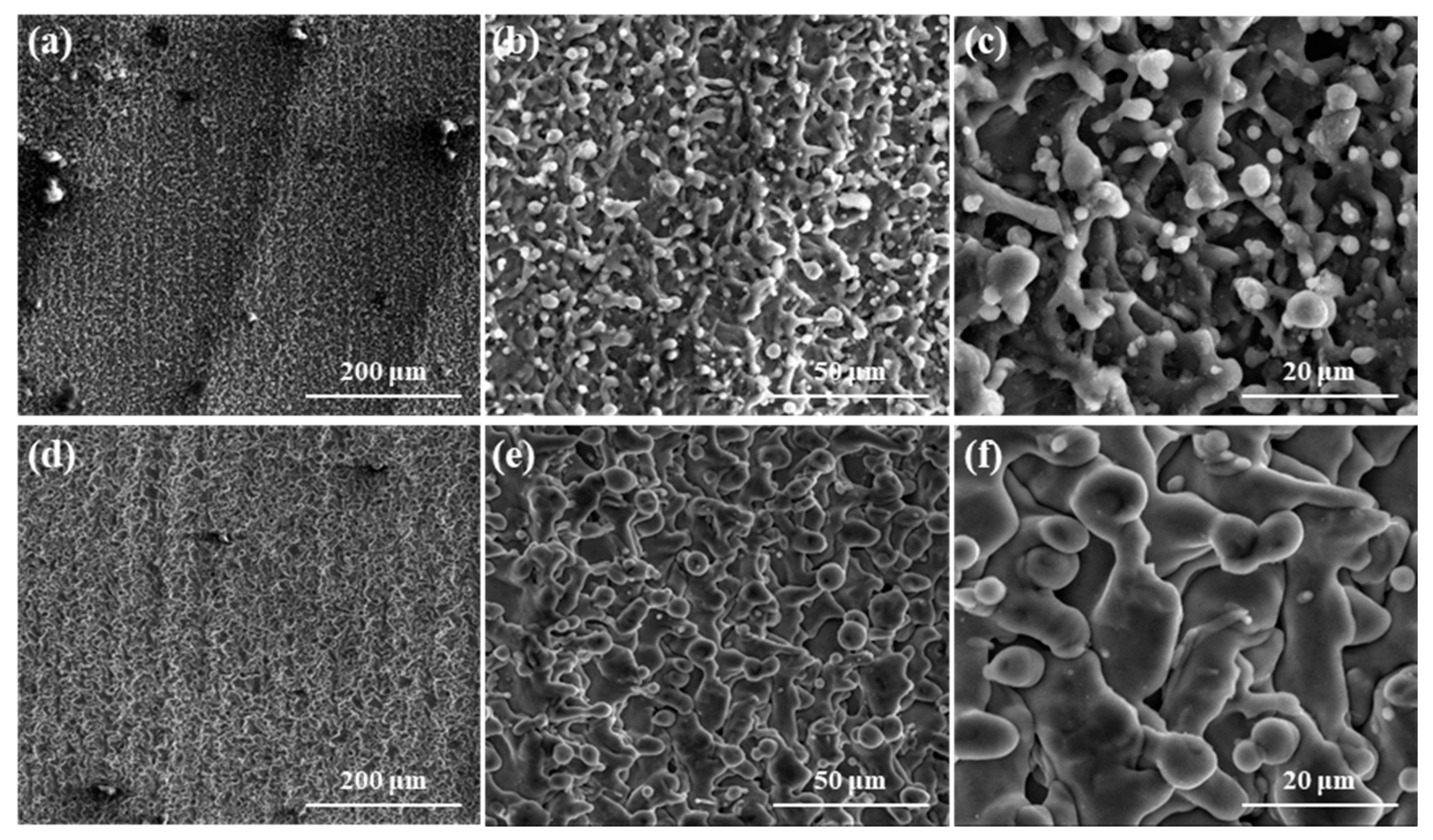
  • After laser treatment, a large number of nanoscale particle structures were distributed on the surface of the microscale rod-shaped micro-structure, and the micro–nano composite structure was formed on the surfaces of both the Al alloy and Ti alloy. The size of the rod-shaped micro-structure on the surface of Al alloy was smaller and more fragmentary than that on the surface of Ti alloy, which was attributed to the higher coefficient of thermal conductivity (CTC), specific heat capacity (SHC), and the lower melting point (MP) of the Al alloy.
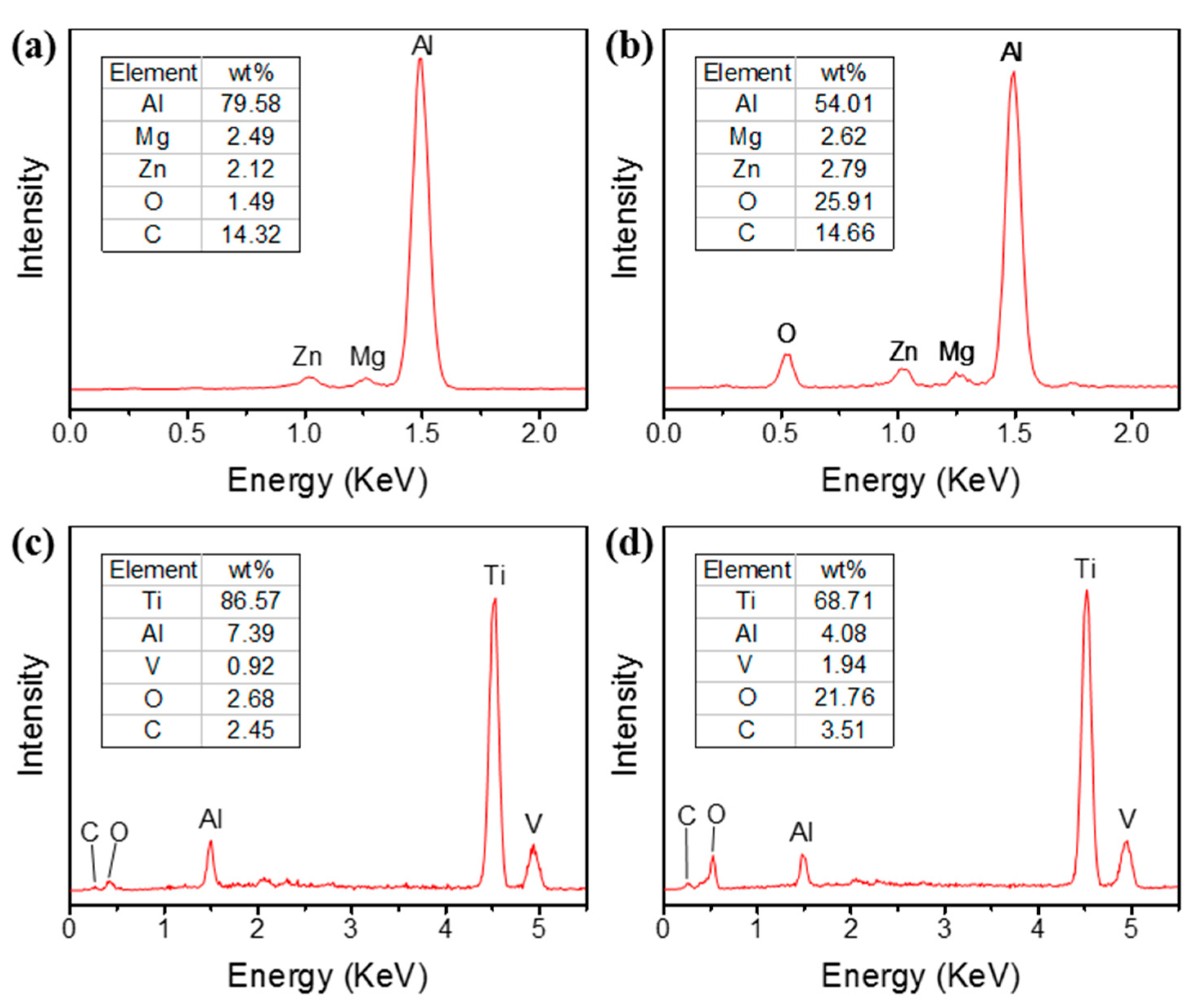
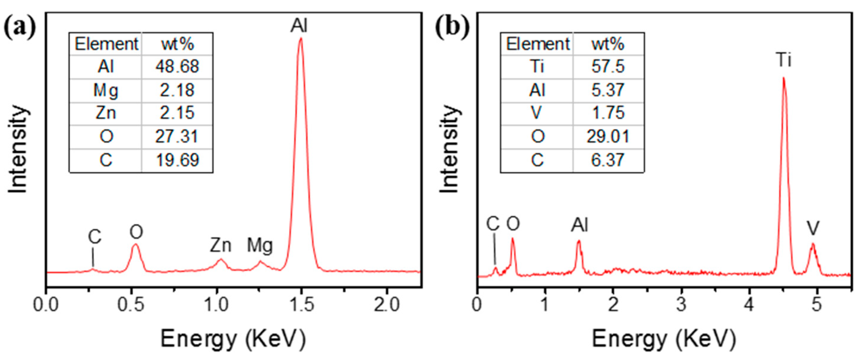
  • The chemical composition changed at the same time as the laser treatment, which was verified by EDS. It was found that the ratio of oxygen on both metal surfaces showed a trend of significant increase, which was due to the ablative oxidation of the metal elements. The surface oxidation of the Al alloy was more intense due to its more fragmentary rod-shaped micro-structure.
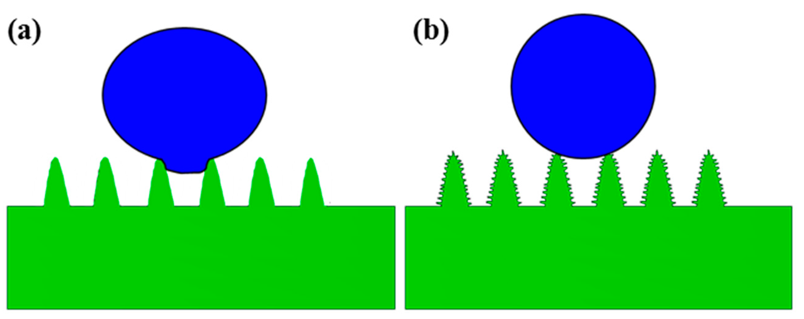
  • The laser-treated surface became hydrophobic or even superhydrophobic from superhydrophilic after 20 days of being placed in the air due to the adsorption of organic matter. The height-to-width ratio of the micro–nano composite rod-shaped micro-structure on the surface of the Al alloy was larger in comparison to that of the Ti alloy, which leads to a larger contact angle (CA) and stronger hydrophobicity.

Author Contributions

Conceptualization, Z.L. and Y.W.; methodology, Z.L. and G.X.; formal analysis, X.W.; investigation, H.P.; writing—original draft preparation, Z.L.; writing—review and editing, Z.L. and Y.W.; project administration, Z.L. and G.X. All authors have read and agreed to the published version of the manuscript.

Funding

This research received no external funding.

Conflicts of Interest

The authors declare no conflict of interest.

References

  1. Mizine, I.; Amromin, E.; Crook, L.; Day, W.; Korpus, R. High-Speed Trimaran Drag: Numerical Analysis and Model Tests. J. Ship Res. 2004, 48, 248–259. [Google Scholar] [CrossRef]
  2. Solomon, B.R.; Khalil, K.S.; Varanasi, K.K. Drag Reduction using Lubricant-Impregnated Surfaces in Viscous Laminar Flow. Langmuir 2014, 30, 10970–10976. [Google Scholar] [CrossRef]
  3. Demirel, Y.K.; Khorasanchi, M.; Turan, O.; Incecik, A.; Schultz, M.P. A CFD model for the frictional resistance prediction of antifouling coatings. Ocean Eng. 2014, 89, 21–31. [Google Scholar] [CrossRef] [Green Version]
  4. Lindholdt, A.; Dam-Johansen, K.; Yebra, D.M.; Olsen, S.M.; Kiil, S. Estimation of long-term drag performance of fouling control coatings using an ocean-placed raft with multiple dynamic rotors. J. Coat. Technol. Res. 2015, 12, 975–995. [Google Scholar] [CrossRef] [Green Version]
  5. Mohanarangam, K.; Cheung, S.C.P.; Tu, J.Y.; Chen, L. Numerical simulation of micro-bubble drag reduction using population balance model. Ocean Eng. 2009, 36, 863–872. [Google Scholar] [CrossRef]
  6. Hao, W.U.; Yongpeng, O.; Qing, Y.E. Experimental study of air layer drag reduction on a flat plate and bottom hull of a ship with cavity. Ocean Eng. 2019, 183, 236–248. [Google Scholar] [CrossRef]
  7. Jiang, L.; Zhao, Y.; Zhai, J. A Lotus-Leaf-like Superhydrophobic Surface: A Porous Microsphere/Nanofiber Composite Film Prepared by Electrohydrodynamics. Angew. Chem. 2004, 43, 4338–4341. [Google Scholar] [CrossRef]
  8. Wang, W.; Wang, G.; She, P.; Sun, H.; Liu, Z.N. A Photo-Curing Method to Prepare Biomimetic Micro-Nano Structure of Butterfly Wing Scale. Appl. Mech. Mater. 2015, 713–715, 2576–2580. [Google Scholar] [CrossRef]
  9. Feng, X.Q.; Gao, X.; Wu, Z.; Jiang, L.; Zheng, Q.S. Superior water repellency of water strider legs with hierarchical structures: Experiments and analysis. Langmuir 2007, 23, 4892. [Google Scholar] [CrossRef]
  10. Lin, J.; Tan, X.; Shi, T.; Tang, Z.; Liao, G. Leaf Vein-Inspired Hierarchical Wedge-Shaped Tracks on Flexible Substrate for Enhanced Directional Water Collection. ACS Appl. Mater. Interfaces 2018, 10, 44815–44824. [Google Scholar] [CrossRef]
  11. Jiang, Z.; Fang, S.; Wang, C.; Wang, H.; Ji, C. Durable polyorganosiloxane superhydrophobic films with a hierarchical structure by sol-gel and heat treatment method. Appl. Surf. Sci. 2016, 390, 993–1001. [Google Scholar] [CrossRef]
  12. Hang, T.; Hu, A.; Ling, H.; Li, M.; Mao, D. Super-hydrophobic nickel films with micro-nano hierarchical structure prepared by electrodeposition. Appl. Surf. Sci. 2010, 256, 2400–2404. [Google Scholar] [CrossRef]
  13. Zhang, H.; Yang, J.; Chen, B.; Liu, C.; Zhang, M.; Li, C. Fabrication of superhydrophobic textured steel surface for anti-corrosion and tribological properties. Appl. Surf. Sci. 2015, 359, 905–910. [Google Scholar] [CrossRef]
  14. Xin, G.; Wu, C.; Cao, H.; Liu, W.; Zhang, G. Superhydrophobic TC4 alloy surface fabricated by laser micro-scanning to reduce adhesion and drag resistance. Surf. Coat. Technol. 2020, 391, 125707. [Google Scholar] [CrossRef]
  15. Yong, J.; Yang, Q.; Guo, C.; Chen, F.; Hou, X. A review of femtosecond laser-structured superhydrophobic or underwater superoleophobic porous surfaces/materials for efficient oil/water separation. RSC Adv. 2019, 9, 12470–12495. [Google Scholar] [CrossRef]
  16. Lin, Y.; Han, J.; Cai, M.; Liu, W.; Luo, X.; Zhang, H.; Zhong, M. Durable and robust transparent superhydrophobic glass surfaces fabricated by a femtosecond laser with exceptional water repellency and thermostability. J. Mater. Chem. A 2018, 6, 9049–9056. [Google Scholar] [CrossRef]
  17. Xin, G.; Rong, Y.; Huang, Y.; Wu, C. Process and mechanism of cutting thermoplastic polyurethane (TPU) film by nanosecond ultraviolet laser. J. Mater. Sci. 2021, 56, 16167–16180. [Google Scholar] [CrossRef]
  18. Fang, Y.; Yong, J.; Chen, F.; Huo, J.; Yang, Q. Bioinspired Fabrication of Bi/Tridirectionally Anisotropic Sliding Superhydrophobic PDMS Surfaces by Femtosecond Laser. Adv. Mater. Interfaces 2018, 5, 1701245. [Google Scholar] [CrossRef]
  19. Höhm, S.; Herzlieb, M.; Rosenfeld, A.; Krüger, J.; Bonse, J. Femtosecond laser-induced periodic surface structures on silicon upon polarization controlled two-color double-pulse irradiation. Opt. Express 2015, 23, 61–71. [Google Scholar] [CrossRef]
  20. He, A.; Liu, W.; Xue, W.; Yang, H.; Cao, Y. Nanosecond laser ablated copper superhydrophobic surface with tunable ultrahigh adhesion and its renewability with low temperature annealing. Appl. Surf. Sci. 2018, 434, 120–125. [Google Scholar] [CrossRef]
  21. Xu, W.; Song, J.; Sun, J.; Lu, Y.; Yu, Z. Rapid Fabrication of Large-Area, Corrosion-Resistant Superhydrophobic Mg Alloy Surfaces. ACS Appl. Mater. Interfaces 2011, 3, 4404–4414. [Google Scholar] [CrossRef]
  22. Xin, G.; Wu, C.; Liu, W.; Rong, Y.; Huang, Y. Anti-corrosion superhydrophobic surfaces of Al alloy based on micro-protrusion array structure fabricated by laser direct writing. J. Alloys Compd. 2021, 881, 160649. [Google Scholar] [CrossRef]
  23. Boinovich, L.B.; Modin, E.B.; Sayfutdinova, A.R.; Emelyanenko, K.A.; Vasiliev, A.L.; Emelyanenko, A.M. Combination of Functional Nanoengineering and Nanosecond Laser Texturing for Design of Superhydrophobic Aluminum Alloy with Exceptional Mechanical and Chemical Properties. ACS Nano 2017, 11, 10113–10123. [Google Scholar] [CrossRef]
  24. Liu, W.; Cai, M.; Luo, X.; Chen, C.; Pan, R.; Zhang, H.; Zhong, M. Wettability transition modes of aluminum surfaces with various micro/nanostructures produced by a femtosecond laser. J. Laser Appl. 2019, 31, 022503. [Google Scholar] [CrossRef]
  25. Long, J.; Zhong, M.; Fan, P.; Gong, D.; Zhang, H. Wettability conversion of ultrafast laser structured copper surface. J. Laser Appl. 2015, 27, S29107. [Google Scholar] [CrossRef] [Green Version]
  26. Yang, Z.; Tian, Y.L.; Yang, C.J.; Wang, F.J.; Liu, X.P. Modification of wetting property of Inconel 718 surface by nanosecond laser texturing. Appl. Surf. Sci. 2017, 414, 313–324. [Google Scholar] [CrossRef] [Green Version]
  27. Boinovich, L.B.; Emelyanenko, A.M.; Emelyanenko, K.A.; Domantovsky, A.G.; Shiryaev, A.A. Comment on “Nanosecond laser textured superhydrophobic metallic surfaces and their chemical sensing applications” by Duong V. Ta, Andrew Dunn, Thomas J. Wasley, Robert W. Kay, Jonathan Stringer, Patrick J. Smith, Colm Connaughton, Jonathan D. Shephard (Appl. Surf. Sci. 357 (2015) 248C254). Appl. Surf. Sci. 2016, 379, 111–113. [Google Scholar]
  28. Kulinich, S.A.; Honda, M.; Zhu, A.L.; Rozhin, A.G.; Du, X.W. The icephobic performance of alkyl-grafted aluminum surfaces. Soft Matter 2015, 11, 856–861. [Google Scholar] [CrossRef] [PubMed] [Green Version]
  29. Yong, J.; Chen, F.; Yang, Q.; Farooqa, U.; Hou, X. Photoinduced switchable underwater superoleophobicity–superoleophilicity on laser modified titanium surfaces. J. Mater. Chem. A 2015, 3, 10703–10709. [Google Scholar] [CrossRef]
  30. Cassie, A.B.D.; Baxter, S. Wettability of porous surfaces. Trans. Faraday Soc. 1944, 40, 546–551. [Google Scholar] [CrossRef]
Figure 1. Morphology of the laser-processed surface scanning electron microscope (SEM) images of the Al alloy with magnification of 500 (a); 2000 (b); and 5000 (c). SEM images of Ti alloy with a magnification of 500 (d); 2000 (e); and 5000 (f).
Crystals 11 01274 g001
Figure 2. Energy dispersive spectroscopy (EDS) spectra of before (a) and after (b) the laser-processing of the Al alloy. EDS spectra of before (c) and after (d) the laser processing of the Ti alloy.
Crystals 11 01274 g002
Figure 3. Profile images of the water droplet on different surfaces. Original surfaces of the Al alloy (a) and Ti alloy (d). Laser-treated surfaces of the Al alloy (b) and Ti alloy (e). Twenty days after the laser treatment of the Al alloy (c) and Ti alloy (f). The outlines of (b,e) are difficult to see from the side. A pipette was used to drop water droplets on the surface and shoot on the front.
Crystals 11 01274 g003
Figure 4. EDS spectra of the Al alloy (a) and Ti alloy (b) placed in the air environment for 20 days after laser treatment.
Crystals 11 01274 g004
Figure 5. Three-dimensional morphology of different surfaces. Before (a) and after (b) laser treatment of the Al alloy. Before (c) and after (d) laser treatment of the Ti alloy. The scale bar is 100 μm.
Crystals 11 01274 g005
Figure 6. Wetting mechanism of water droplets on surfaces with micro-structure (a) and micro–nano composite structure (b).
Crystals 11 01274 g006
Table 1. CAs of the original surfaces and the surfaces of 20 days after laser treatment.
Al AlloyTi Alloy
Original20 days after laser treatmentOriginal20 days after laser treatment
39 ± 2°157 ± 1°53 ± 3°147 ± 2°
Table 2. Roughness of surfaces before and after laser treatment.
Roughness Characterization ParameterAl AlloyTi Alloy
BeforeAfterBeforeAfter
Maximum peak height Rp/μm1.57913.2753.65513.233
Maximum sag height Rv/μm5.35912.5876.93925.863
Contour mean difference Ra/μm0.2872.7623.9274.770
Ratio of height to width Str/0.1860.5110.2430.710
Void volume Vv/(mL/m2)0.4415.5020.7325.536
Publisher’s Note: MDPI stays neutral with regard to jurisdictional claims in published maps and institutional affiliations.

