Article

Textile-Reinforced Concrete Versus Steel-Reinforced Concrete in Flexural Performance of Full-Scale Concrete Beams

Department of Civil Engineering, College of Engineering, King Saud University, Riyadh 12372, Saudi Arabia
Crystals 2021, 11(11), 1272; https://doi.org/10.3390/cryst11111272
Submission received: 22 September 2021 / Revised: 5 October 2021 / Accepted: 13 October 2021 / Published: 20 October 2021
(This article belongs to the Special Issue Advances in Green Building Materials and Structural Performances)

Abstract

:
The effectiveness of textile-reinforced concrete (TRC) and steel-reinforced concrete (SRC) in the flexural performance of rectangular concrete beams was investigated in this study. To better understand TRC behaviour, large-scale concrete beams of 120 × 200 × 2600 mm were tested and analysed in this work. Cover thickness, anchoring, and various layouts were all taken into consideration to assess the performance of beams. In addition, bi-axial and uni-axial TRC beams and SRC beams were classified according to the sort and arrangement of reinforcements. The findings showed that anchoring the textiles at both ends enhanced load resistance and prevented sliding. The ultimate load of the tow type of textile reinforcement was higher, attributed to the increased bond. Variations in cover thickness also change the ultimate load and deflection, according to the findings. Consequently, in this investigation, the ideal cover thickness was determined to be 30 mm. Furthermore, for the similar area of reinforcements, the ultimate load of TRC beams was noted up to 56% higher than that of the SRC control beam, while the deflection was roughly 37% lower.

1. Introduction

Construction of structures employing materials with improved physical performance and durability has become increasingly important in recent years; the new goal is to create structures that are more sustainable, durable, and require less maintenance. As a secondary reinforcement, discontinuous fibres have been used in the concrete to prevent cracking [1,2]. This technology cannot replace primary steel reinforcement. Carbon and glass fibres have been used in reinforced concrete (RC) structural elements for decades. It is important to note that these materials do not undergo corrosion in the traditional sense, allowing for advantages in structural design such as smaller cover dimensions and a thinner structural element [3,4].
Roving fibres have recently been researched as a primary reinforcing material to substitute steel bars in concrete components. To solve such shortcomings, a novel group of composite materials integrating high-strength textile fibres has been proposed as a structural component for weak RC parts, namely the textile-reinforced concrete (TRC) [5]. TRC is a lower-cost alternative to traditional SRC, is harmless for workers, and is companionable with concrete and masonry matrices. Several research studies [6,7] have looked at the bonding effectiveness of TRC and concrete substrate. TRC has been used successfully in the building industry all around the world. With a limited number of textile layers, TRC has also been explored for flexural strength [8,9,10]. The experimental results, on the other hand, confirm TRC’s usefulness as a structural member.
TRC is a material made up of fine-grained concrete and textile fibres. The textile material could be alkali-resistant multi-filament roving, and the concrete is usually built with a coarse aggregate size of 10 mm [11,12]. This combination produces a composite material with desirable characteristics, including higher tensile strength, better corrosion resistance, lighter weight, and thinner cover [13,14]. TRC’s components have significant benefits over FRC, which can be used in areas with high stress. According to Papanicolaou and Papantoniou [15], the properties of TRC are entirely depend on whether it is placed in the desired location and in sufficient quantity, whereas typical fibres that are arbitrarily spread and directed are inefficient. Due to their random orientation, the fibres in FRC are not fully utilised in fracture management, strengthening, or stiffening. According to Tysmans et al. [16], because textile reinforcement has high tensile strength, it might be employed as a major reinforcement instead of steel.
In addition, the existence of fibres does not affect the strength of a beam’s compression zone [17]. TRC combines the benefits of short-fibre-reinforced concrete and conventional SRC. Furthermore, TRC has a substantially lower volume of fibres than FRC. More than 3% FRC is necessary for concrete to be reinforced adequately due to fibres’ lower required dosage and the increased fibre consumption efficiency [18]. TRC will result in structures with cheaper costs [19,20,21]. Given all of these advantages, a greater knowledge of these materials’ behaviours will enable them to be employed more effectively in composite materials and, as a result, will assist the building industry more. TRC’s behaviour needs to be better understood before it can be used reliably.
The existing literature does not fully address the comparison of the flexural performance of TRC and SRC beams when textile fibres are used as the primary reinforcement in various layouts. In addition, the flexural behaviour of TRC has not been thoroughly investigated, and more data are required before it can be safely used. Accordingly, the primary objective of this research work was to evaluate the effect of textile fibres as the main reinforcement on the flexural performance of full-scale TRC beams and investigate how the textile fibres contribute to the decrease in crack formation and deterioration in comparison to SRC beams. Along with flexural performance in terms of load-deflection behaviour, the performance of TRC beams for other parameters such as various anchored roving, fabrics’ cross-sectional area, textile fibre layering, textile geometries, and cover thicknesses were also investigated.

2. Materials and Methods

2.1. Materials

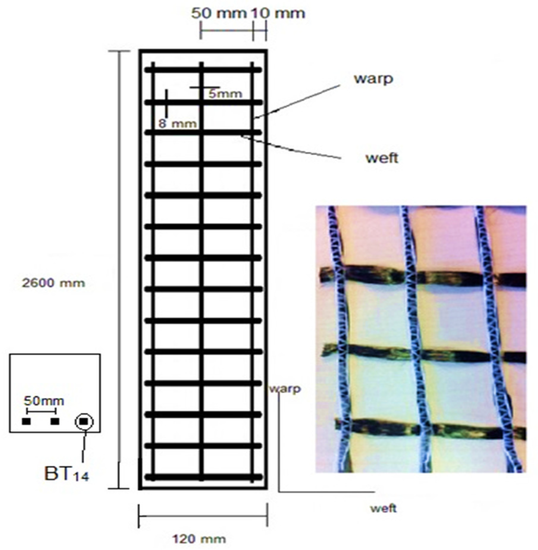
The Portland cement (CEM I) employed in this study has a specific surface area of 3990 cm2/g, which fulfils the standard requirements in BS EN 197-1. Fine aggregates that passed through the sieve size of 4.75 mm were used. Additionally, a crushed quartzitic aggregate was used. It has a specific gravity of 2.7, an irregular form, and a maximum size of 10 mm. Furthermore, it has 0.50% water absorption. A polymer-based Superplasticizer was used to help maintain concrete’s flowability, delivering a steady dose of 1% of the binder. In this study, the multi-filament carbon fibre (FORMAX, UK) with various lengths were used as fibrous reinforced materials and then were cut into the desired lengths based on the size of beams. Carbon fibres with different tow-shape arrangements, as illustrated in Figure 1, were used. The tensile strength of the fibres was found to be 4000 MPa with a filament diameter of 7 µm. Table 1 shows the engineering parameters of textile fibres offered by the provider.

2.2. Concrete Proportions

Table 2 reveals the mixture proportions of the plain concrete used for the production beams. In the production of plain concrete, the water/cement ratio was the same for all mixtures at 0.35 to attain the desired strength, and the average 28-day compressive strength of conventional concrete was 85 MPa. Fresh concrete was poured into the planned formworks after the concrete has been prepared. Then, the textile fibres in the form of reinforcement with the desired lengths were put into the beams in suitable placements. The formworks were filled with fresh concrete with correct finishing after the proper positioning of the textile fibres. SRC beams were also made using the same process. The specimens were then covered and remained at room temperature for 24 h after casting to prevent evaporation. After that, the samples were de-moulded and placed in water for 28 days to cure.

2.3. Testing Methods

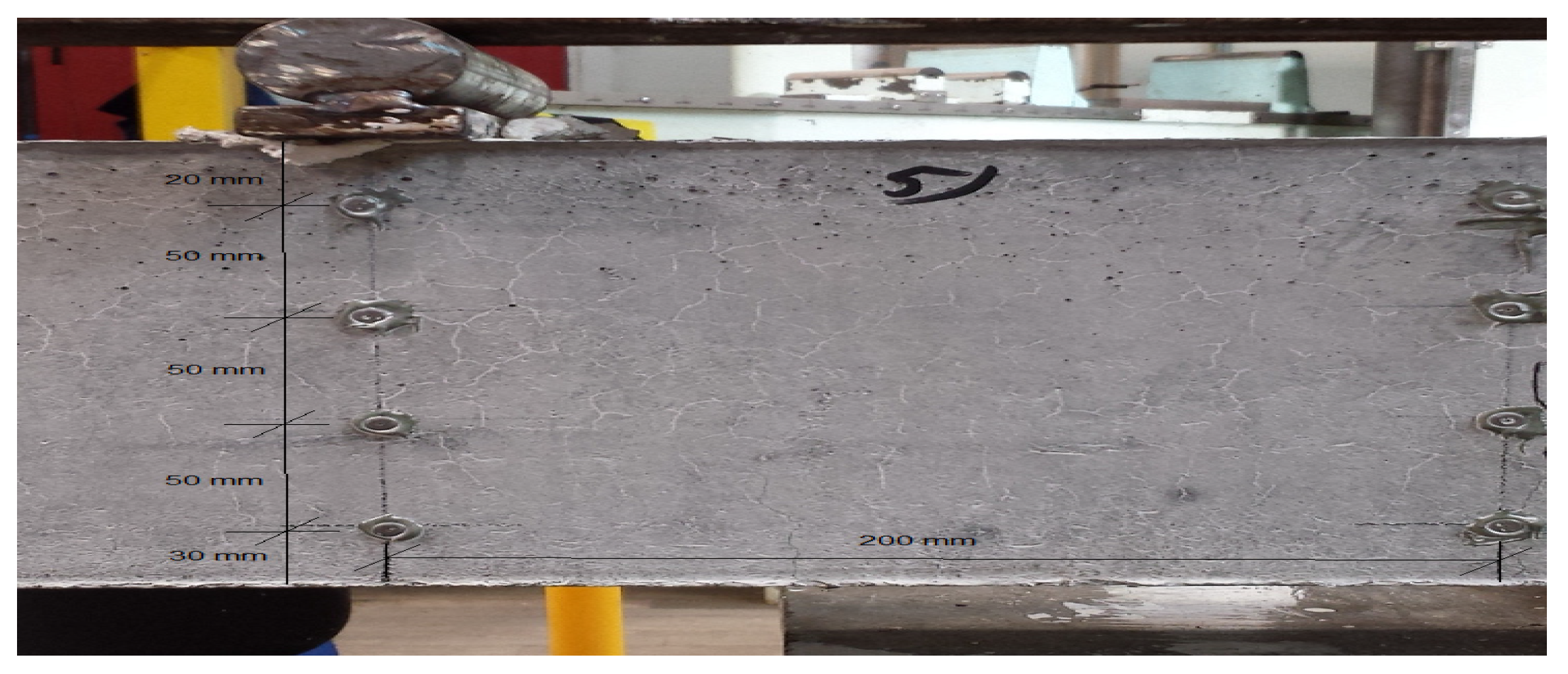
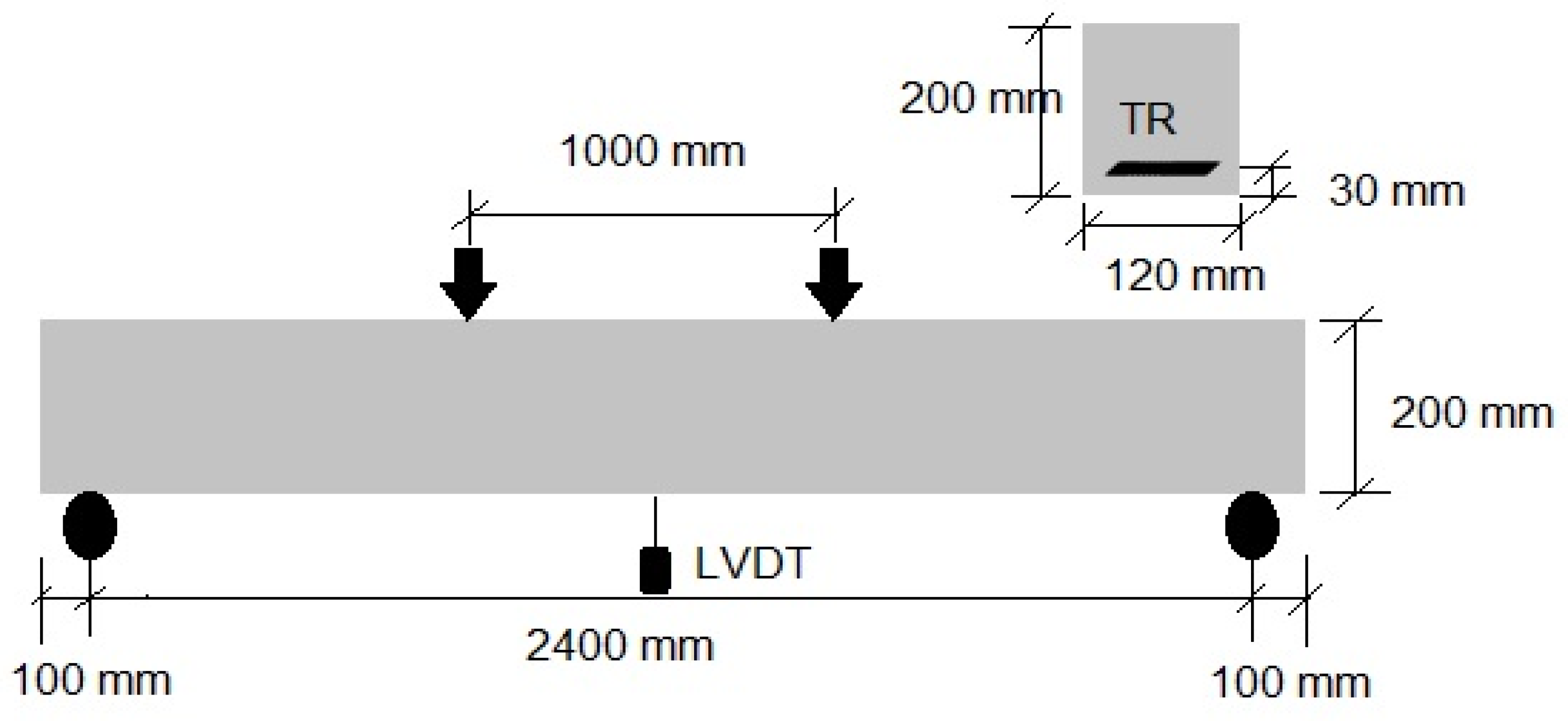
As illustrated in Figure 2, beams of size 120 mm × 200 mm × 2600 mm were prepared for flexural strength using a four-point bending test procedure. To calculate the deflection, an LVDT device was placed in the centre of each beam. The test was carried out on a ToniPACT 3000 testing equipment with a 150 kN capacity and a 0.1 kN/sec loading rate. Some beams had their crack positioning and cracked width distinguished. The load versus deflection was recorded using a computerised data-gathering device. The loading resolution was 0.01 kN, and the deflection resolution was 0.001 mm. The surface of the beams was painted white to aid in noticing the initial crack. In addition, to measure the surface strain, demecs strain gauges were attached between the two loading sites on the surface of samples, as shown in Figure 3. Using an optical microscope, the widths of cracks on the beams were also measured.
The number of warps in bi-axial textile for large-scale beams was 3, while the number of warps in uni-axial textiles in each layer was changed to 3 and 4, with a fixed cover of 30 mm. One arrangement was employed in bi-axial TRC beams, with a 5 cm spacing amongst each warp, with 3 warps in each layer. BT(5cm)14-Anch-2.6 denotes 14 layers of textile piled with a 5 cm space between warps. As shown in Figure 4, the fabric was placed in the warp direction of a bi-directional textile. Before 10 mm from both ends of the 2.6 m beam, the reinforcement was anchored. The reinforcement is held in place by attaching the anchored textiles to the crossing bar located on the top of the formwork. Owing to the ease and simplicity of forming the textiles inside, the formworks can be regarded as a benefit of textile reinforcement.
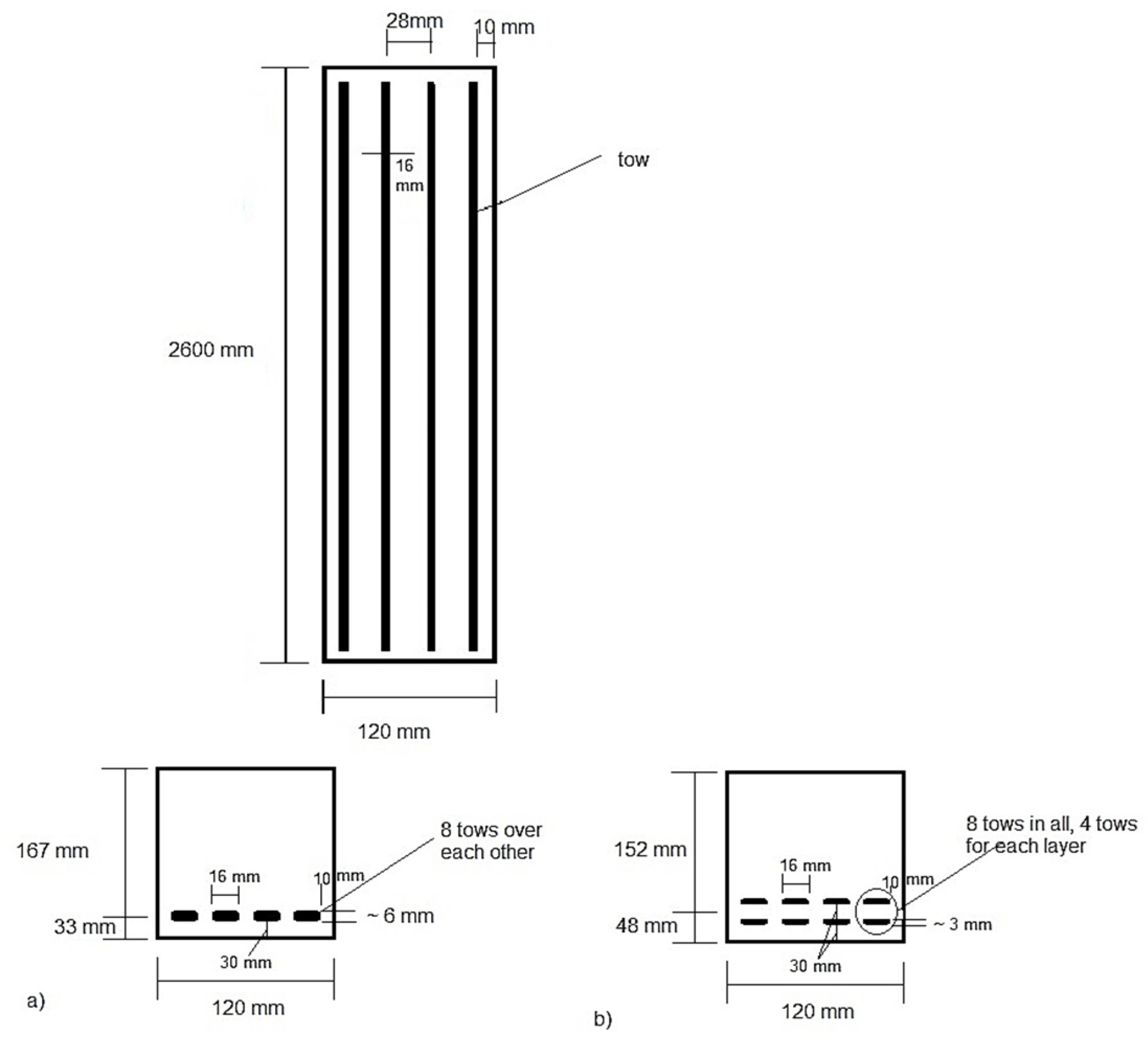
In addition, 50k tow textiles were employed in uni-axial TRC beams. The end of the textiles was retained anchored or straight. Furthermore, all the reinforcement was alienated into three levels, with a horizontal spacing of 2 cm between tows in each layer. 4UT8-S-2.6 denotes eight tows piled over each other in TRC beams with straight ends. The quantity of uni-axial textiles in each layer was 4 (4U), and the ends of textiles were straight (S), as shown in Figure 5a. 4UT8-S-L-2.6 also denotes eight tows separated into two levels (L). Each layer had 4 (4U) uni-axial reinforcement, and the reinforcement end was straight on both sides, as shown in Figure 5b. Furthermore, 4UT8 or 12-Anch-2.6 refers to 8 or 12 tows piled on top of each other in the anchored form of TRC beams. Each layer has 4 (4U) uni-axial reinforcement, with the anchored (Anch) reinforcement on both sides of beams. It is similar to Figure 5a; only the edge is fastened here. Eight tows separated into two levels are represented by 4UT8-Anch-L-2.6 (L).
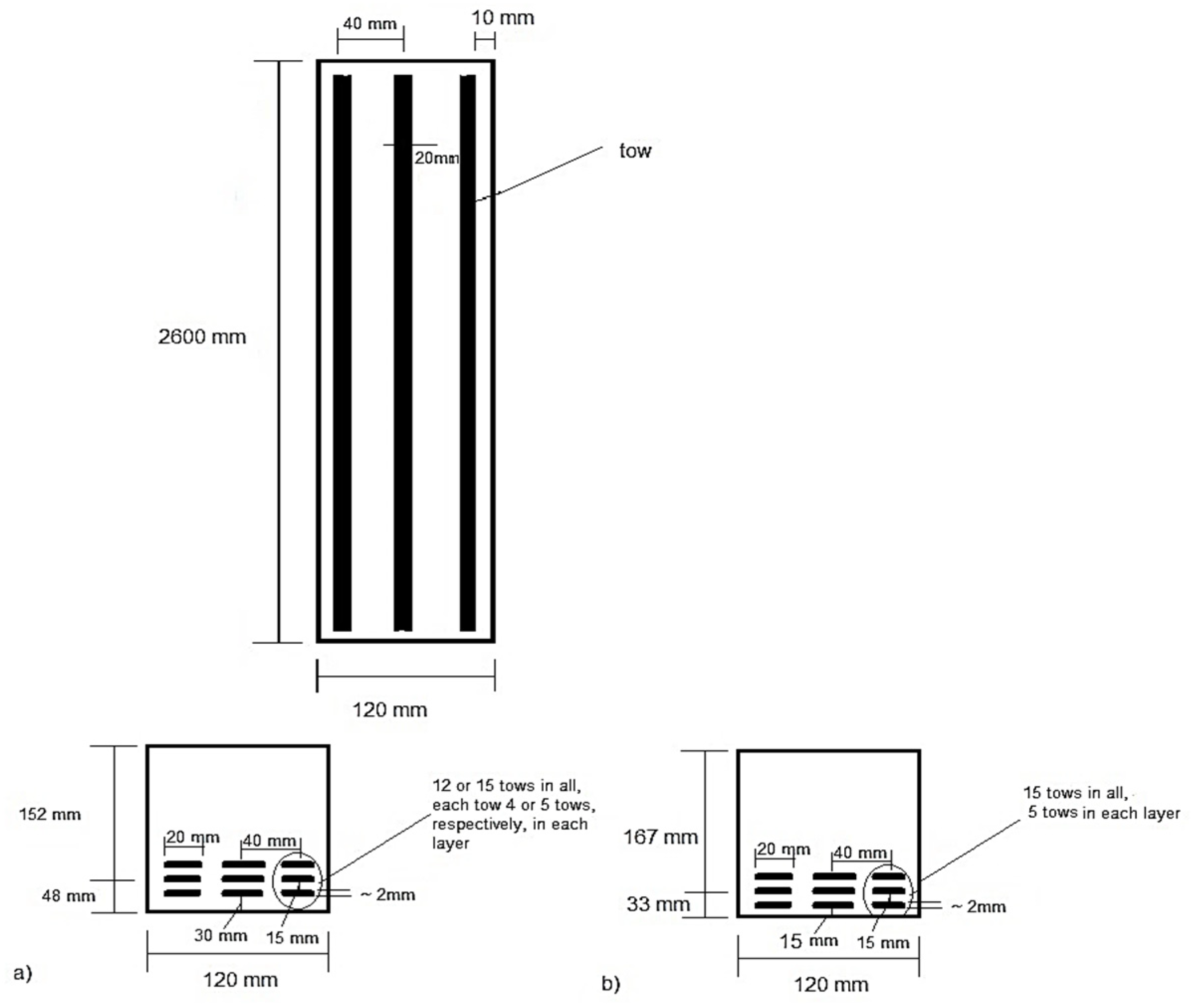
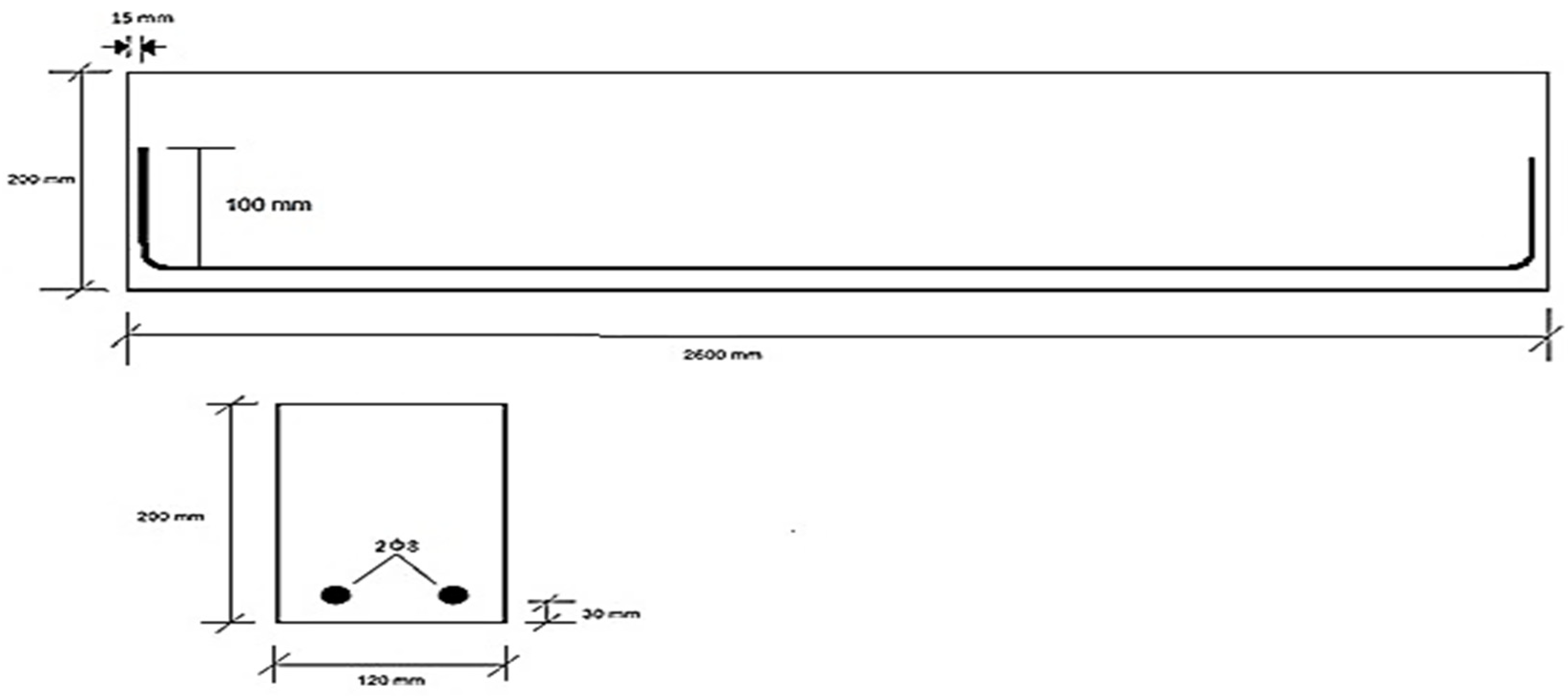
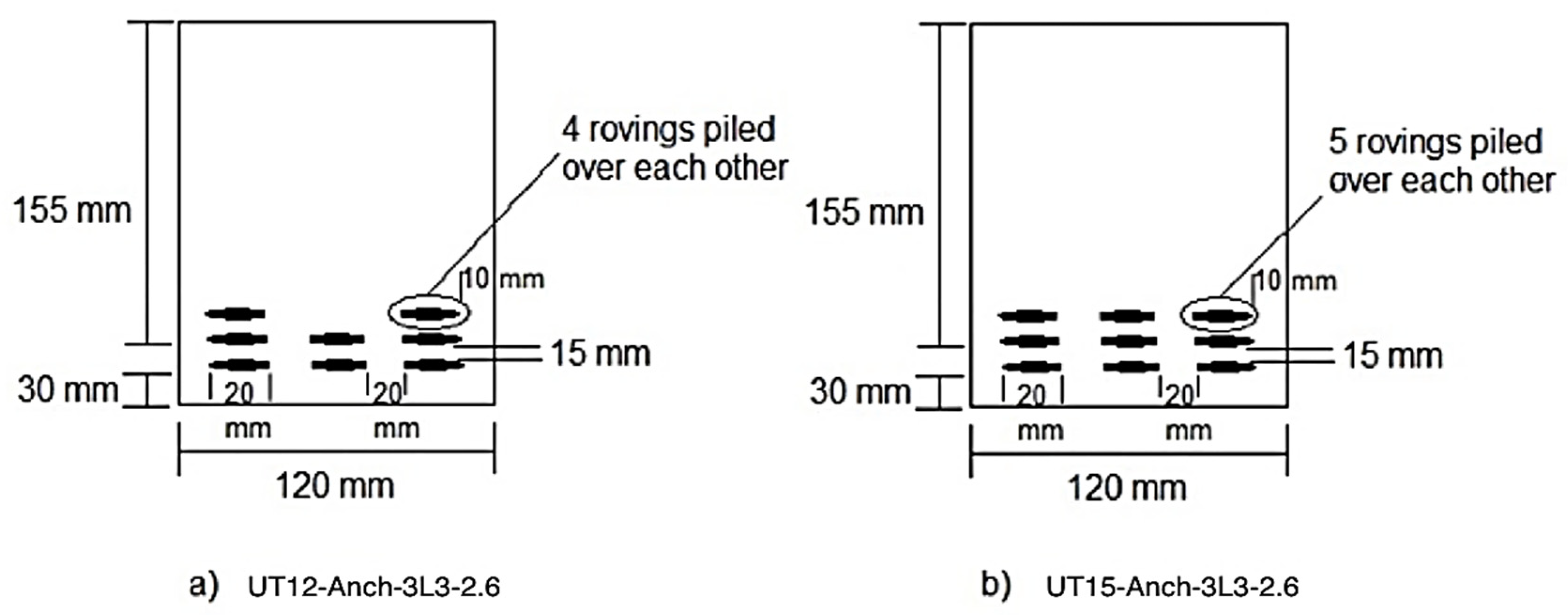
Each layer has 4 (4U) uni-axial reinforcement, with the anchored reinforcement end at both sides of beams. It is similar to Figure 5b, and only the edge is fastened here. Twelve or fifteen tows divided into three levels are represented by 3UT12 or 15-Anch-L3-26. (L3). Each layer had 3 (3U) uni-axial reinforcement and anchored reinforcement ends, as shown in Figure 6a. 3UT15-Anch-L3-2.6-C15 or 60 denotes a total of 12 or 15 tows separated across three layers (L3). Each layer has 3 (3U) uni-axial reinforcement, with the anchored reinforcement ends. The cover thickness was 15 mm or 60 mm, as indicated in Figure 6b. Further, steel bars of 8 mm diameter were utilised as reinforcement in the SRC beam, as revealed in Figure 7. The characteristics of tested beams are given in Table 3. The beam sample was then tested through the flexural test, the load-deflection performance was experimentally investigated, and the outcomes of TRC beams were compared with the SRC beam.

3. Results

3.1. Bi-Axial TRC Beams

Bi-axial textiles with a 5 cm spacing amongst each warp were utilised to reinforce the TRC beams. There were 14 bi-axial textile textiles placed on top of each other. Each fabric was made up of three warps. Table 4 contains the data, and Figure 8 depicts the load-deflection curve. For the ultimate load of 11.8 kN, the bi-axial TRC beam with a fibre volume fraction of 0.57% and an effective fibre area of 80.7 mm2 showed a maximum deflection of 14.5 mm. The behaviour and patterns of fractures in a bi-axial TRC beam of BT(5cm)14-Anch-2.6, 50k, are also shown in Figure 9. It can be seen that the fracture occurred at the centre of the beam, with a relatively big crack size, indicating the beam’s low ductility.

3.2. Uni-Axial TRC Beams

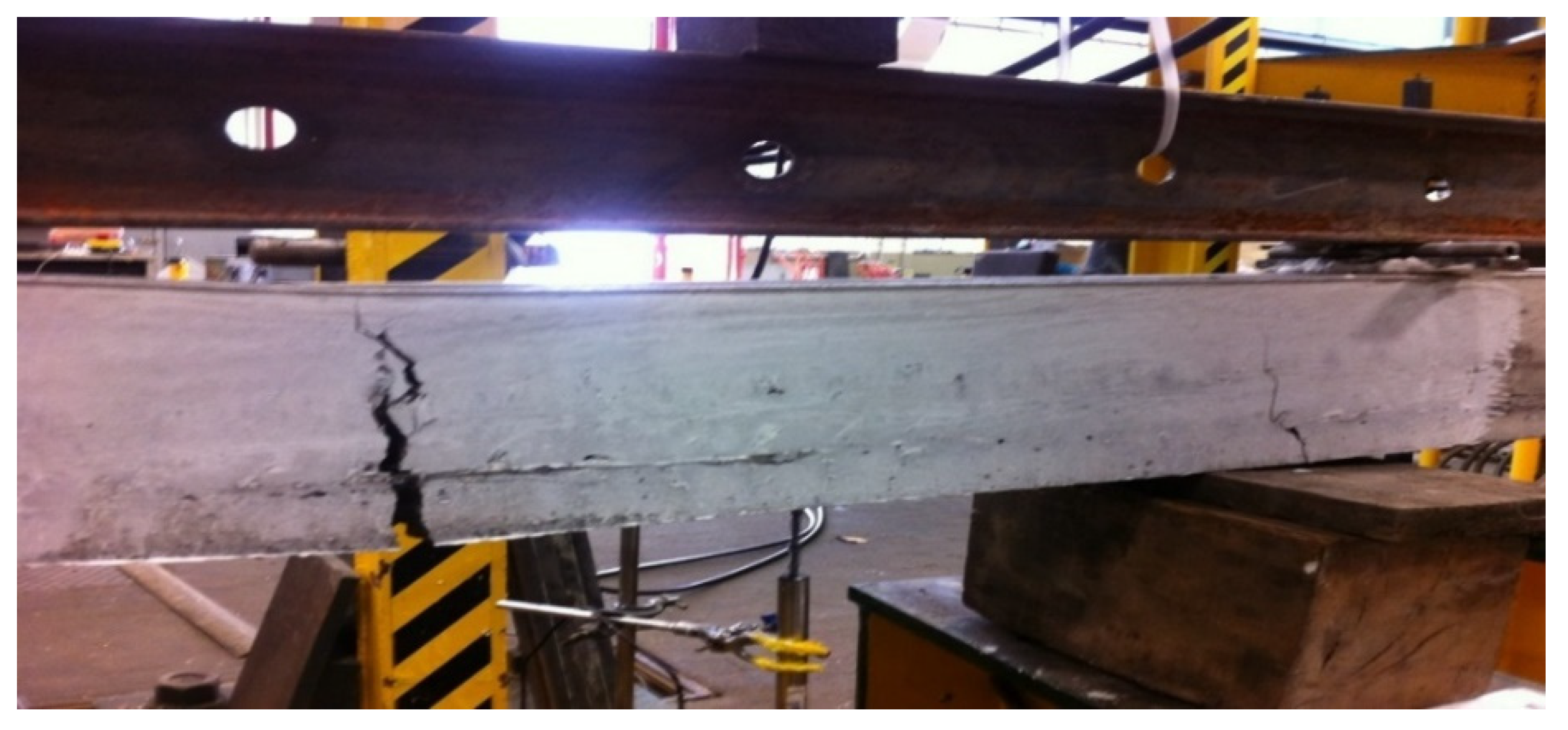
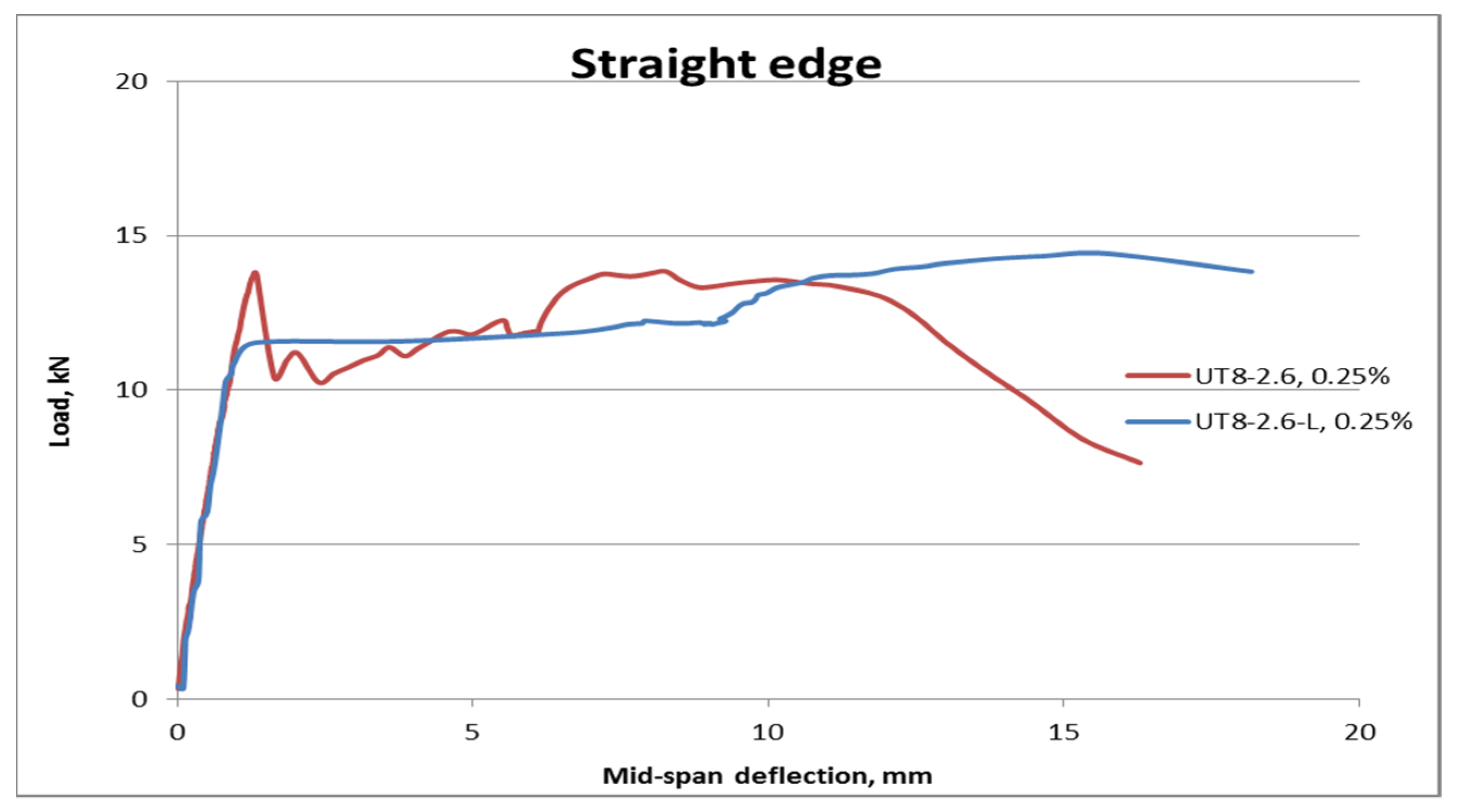
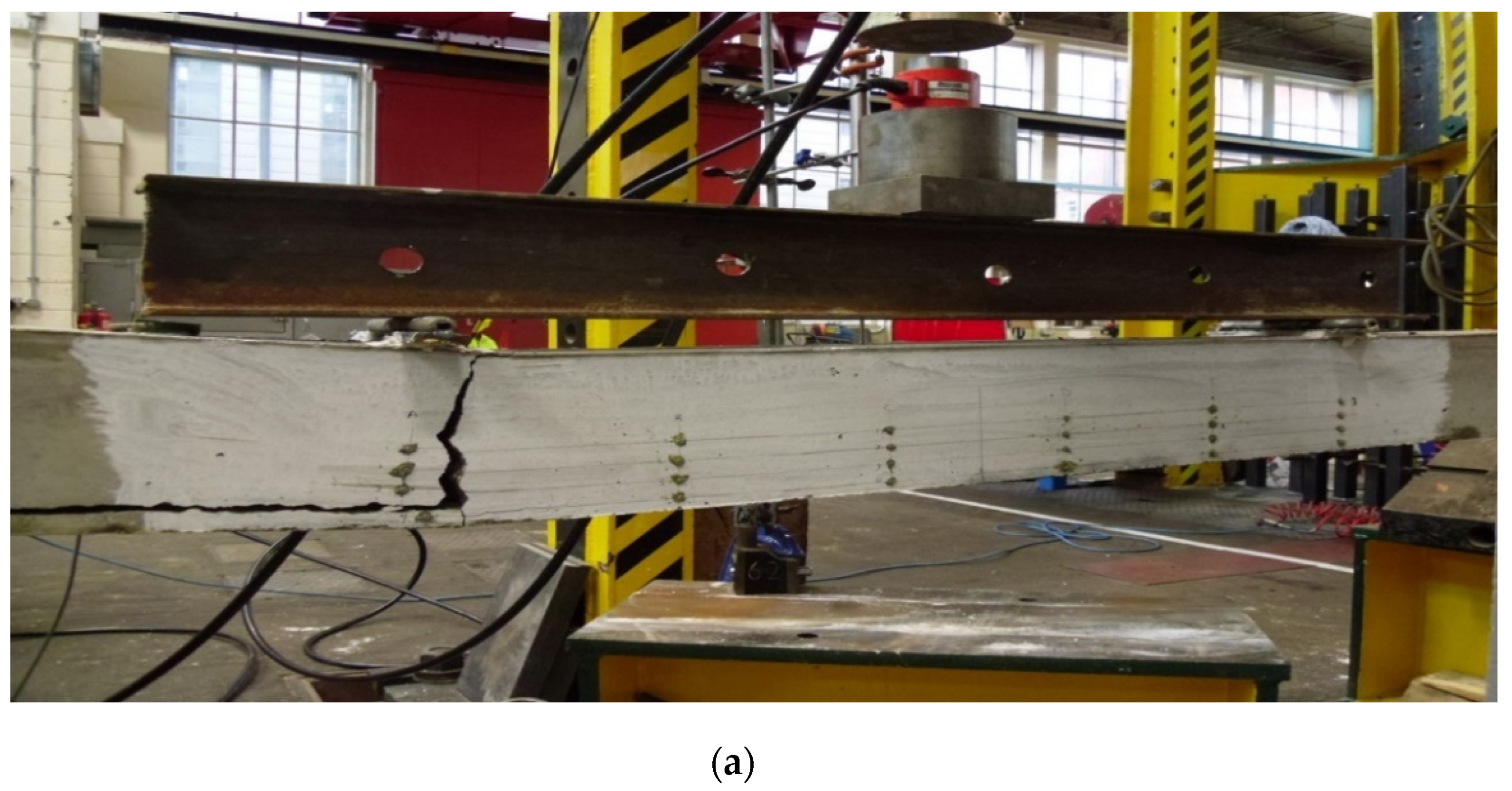
The uni-axial TRC beams with tow reinforcements were tested. The findings are divided into straight and anchored groups based on the reinforcement arrangement at the end of the beams. Based on the thickness of the cover, they are divided into three sub-groups. Table 5 displays the outcomes of uni-axial TRC beams with the straight end on both sides of the beams. Figure 10 depicts the load-deflection performance of uni-axial TRC beams with various configurations. It can be seen that the uni-axial TRC beam of UT8-L-2.6, 50k, with two layers of textiles obtained the maximum deflection of 15.7 mm for the ultimate load of 14.4 kN, which is greater than the values of 9 mm and 13.8 kN recorded for the UT8-2.6, 50k beams with one layer of textile. In addition, Figure 11 shows the failure modes and the crack patterns of the TRC beams for this category. The uni-axial TRC beams with a straight edge and two layers of textiles were more ductile and had smaller fracture sizes.
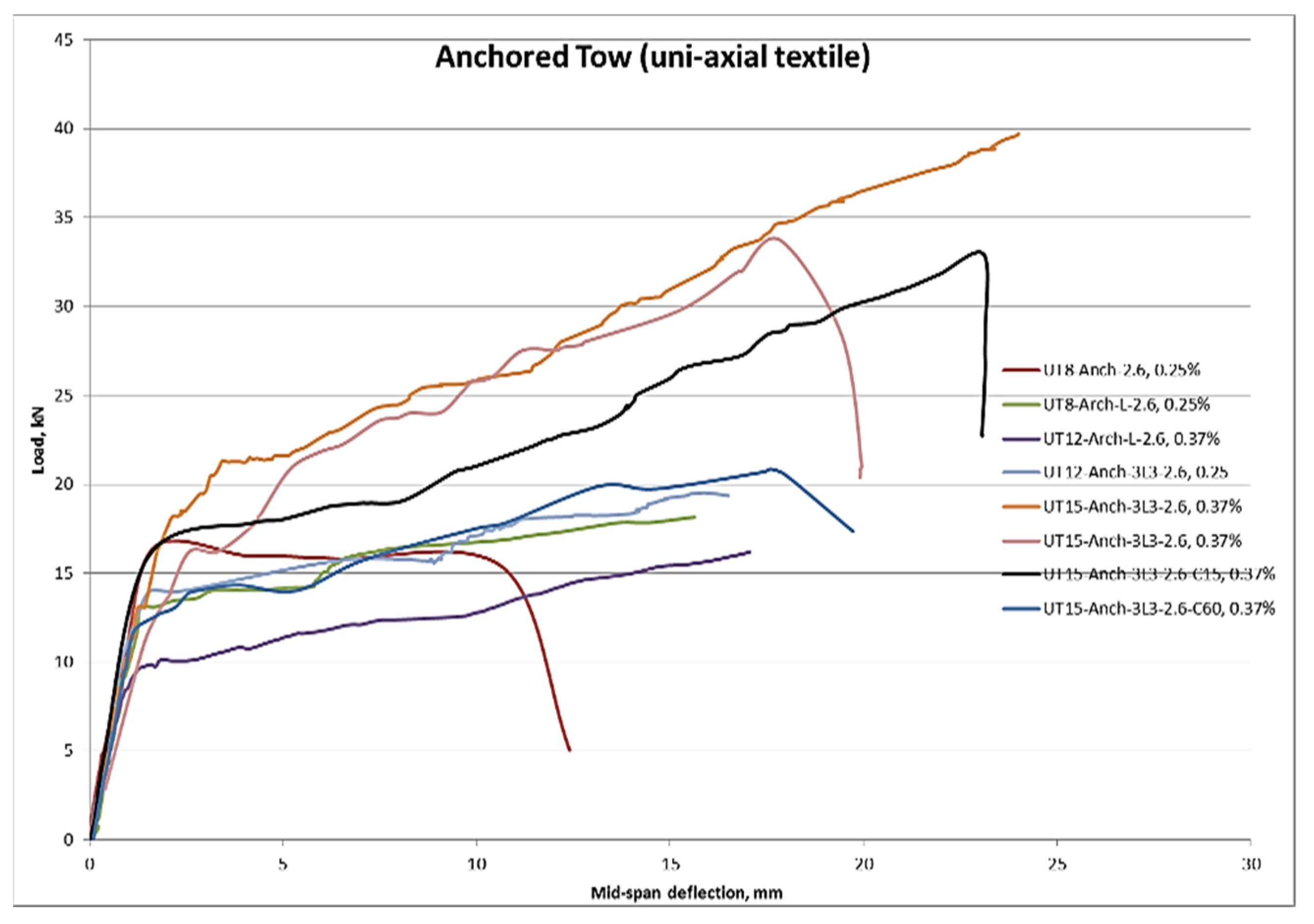
Table 6 shows the findings of uni-axial TRC beams anchored at the ends of the beams. It can be seen that there is a range of layouts for textile reinforcements with various layers. In this regard, L implies that tows were alienated into 2 layers with 15 mm gaps. Additionally, if L is not revealed, the tows are placed in one layer only. For example, 3L3 indicates that the textiles were placed into three layers with 15 mm spacing amongst them, and three preceding L indicates that each layer has three uni-axial tows. In all beams, the cover thickness was kept as 30 mm, unless specified as C15 or C60, in which the cover thickness was 15 mm or 60 mm, respectively. Table 6 shows that at the same number of fibres, the ultimate load results vary significantly. Figure 12 also showed that the flexural behaviour of beams in terms of ultimate loads and deflections changed as the layouts of anchored end uni-axial textiles changed. The ultimate loads and deflections improved dramatically when the fibre dosages were increased, with values of 39.3 kN and 23.6 mm observed, respectively, for the UT15-Anch-3L3-2.6, 50k, beam with a fibre volume fraction of 0.37%. In addition, Figure 13 shows the crack patterns and failure modes of uni-axial TRC beams, which are more ductile and have smaller crack sizes.

3.3. Steel-Reinforced Beams

Full-scale SRC beams were also reinforced with two steel bars of 8 mm diameter in this study, indicating that they were SRC beams and control samples. The steel bars were anchored, and the bottom cover was 30 mm thick. The steel-bar-reinforcing area was preferred to be comparable to the largest cross-sectional area of the TRC beams to compare and validate the results. Furthermore, SRC beams, utilised as control samples, were designed using the same design idea as TRC beams. Table 7 summarises the findings of SRC beams, while Figure 14 depicts the load-deflection performance of the SRC beam as the control sample. With ultimate load and deflection of 24.5 kN and 40.5 mm, respectively, the SRC beam with an effective area of 100.5 mm2 and fibre content of 0.42% displayed better ductility. The steel-reinforced concrete fracture pattern is likewise shown in Figure 15, and the failure mechanism is more ductile, with microscopic cracks.

4. Discussion

The impact of anchored roving on TRC beam performance was examined. The straight and anchored TRC beams were thus tested. Table 8 displays the flexural performance of TRC beams with the same cross-section area and having straight and anchored end reinforcements. Figure 16 shows the reinforcement details, with the reinforcement placed down in a single layer. It was found that the load capacity of UT8-Anch-2.6 was raised due to anchoring the reinforcement. Compared to UT8-2.6 with straight-end reinforcements, the load capacity of UT8-Anch-2.6 rose by about 24% to 16.5 kN. The outcome was expected because the tows were anchored, preventing the filaments from slipping freely [22,23]. The tows slipped in UT8-2.6 due to the flexural loading, causing the lengths to remain unchanged. The slickness was caused by the reinforcement’s straight end, which could not provide expansion length, the short interaction area amongst matrix and textile reinforcements. The delamination crack, which is the outcome of supporting the rovings on top of each other, dominates the crack behaviour.
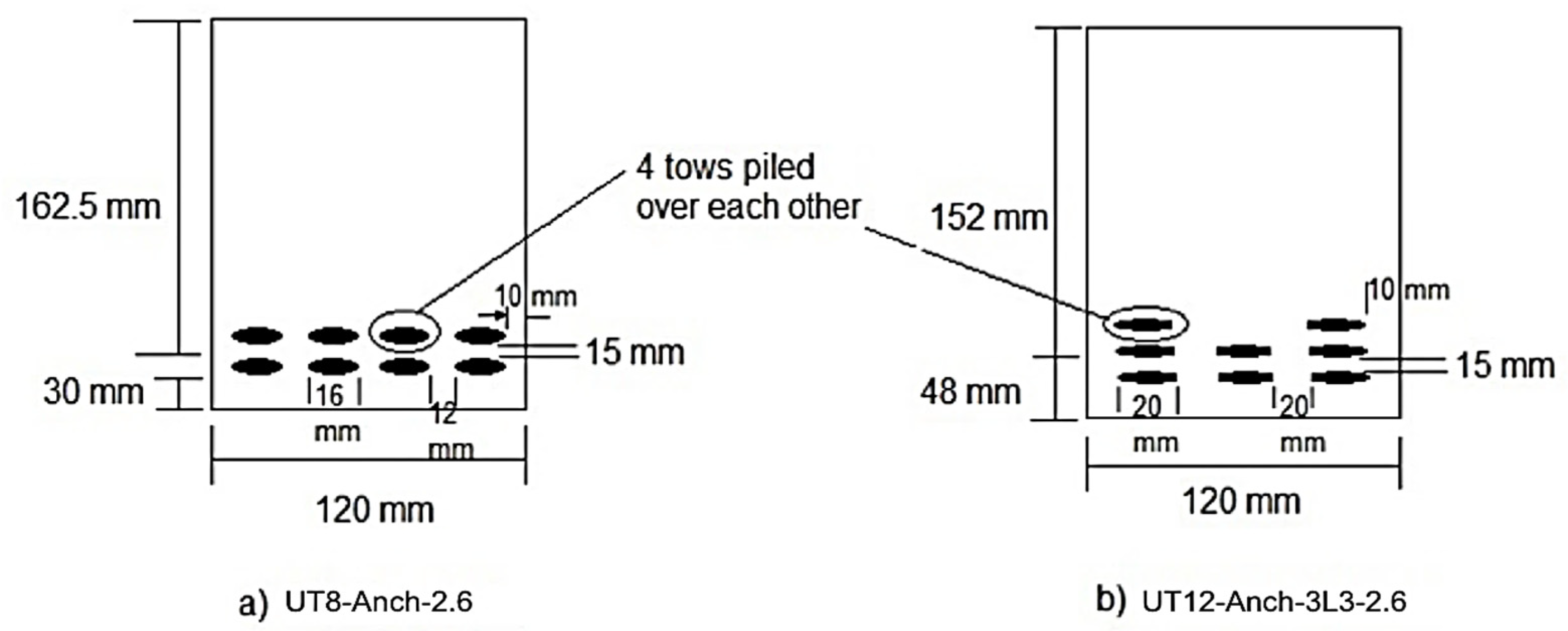
In addition, the influence of textile fibre layering on beam performance was examined. As previously stated, the UT8-Anch-2.6 TRC beam failed quickly in the loading process since the tow textiles were stacked on top of each other, causing penetration issues and reducing the interaction area with the concrete matrix. Consequently, the tows were separated into two layers at a similar area, with four tows put over each other and four in horizontal uni-axial directions in each layer [24]. Furthermore, the tow textiles were placed into three layers and three horizontal orientations, as shown in Figure 17, to assess the consequence of layering on the performance of TRC beams, which will enhance the contact area and, therefore, the higher load-bearing capacity of beams. In the effective depth calculation, the thickness of the tows was considered insignificant. The load-bearing capability will theoretically decrease as the effective depth decreases [25]. The experimental results revealed that layering and reforming reinforcement schemes increased the ultimate loads of TRC beams.
From Table 9, it can be observed that the UT12-Anch-3L3-2.6 had the maximum load capacity. Compared to UT8-Anch-2.6, which is entirely anchored beams, it rose by about 18%, where UT8-Anch-L-2.6 beam enhanced by about 10%. Because of the reinforcing layers, the ductility was also improved. Owing to the dividing of the textile tows into different layers, the bearing capacity was enhanced. However, the adequate depth was lowered due to the layering, and it resulted in the enhancement of beams owing to the rise in the contact area of fibres and concrete matrix [26]. While tow reinforcement is divided into two or three layers, the number of exposed filaments that can contact the concrete increases, improving the bond, while the number of inner fibres decreases [27]. In addition, by separating the tow reinforcements into three horizontal directions instead of four, the roving can be expanded to a width of 20 mm rather than 16 mm, as shown in Figure 17. This enhanced the amount of exposed area that might interact with the concrete. As a result, the increased bond compensates for the projected drop in load capacity due to the reduced adequate depth. In addition, the failure mechanism for UT8-Anch-2.6 and T12-U-Anch-3L3-2.6 TRC beams was modified from delamination to flexural failure. Furthermore, the number of cracks in UT8-Anch-L-2.6 and UT12-Anch-3L3-2.6 grew to 4 and 5, respectively. This difference in crack formation indicates that improving the link between filaments and matrix is critical [28].
The influence of the fabrics’ cross-sectional area was also studied. The cross-section area of textiles fibres in the loading path was discovered to have a considerable impact on the behaviour of TRC beams. Table 10 shows the outcomes of the experimental test. It was evident that raising the Af improves the load-bearing capacity of TRC beams [29]. It was noted that with the rise in cross-section area of textiles by 50%, the ultimate loads increased by about 100%, making it twice as much as the UT12-Anch-3L3-2.6 TRC beam. Therefore, due to this improvement in the load-bearing capacity, the beams’ performance was more ductile. The first crack load was 26% higher when the area was increased by 50%. Furthermore, the findings demonstrated that one of the essential elements to consider while studying the performance of TRC beams is the area of reinforcement. As shown in Figure 18, the textile-reinforcing layout should not be overlooked since it significantly enhanced the fibres’ interaction area with the concrete. Additionally, the number of cracks increased considerably as the cross-section area of textiles changed. Five cracks were counted before failure for the UT12-Anch-3L3-2.6 beam, while this number increased to 13 cracks for the UT15-Anch-3L3-2.6 beam. As demonstrated in Figure 19, a significant rise in the cross-section area of textile reinforcements in addition to the appropriate planning can result in an outstanding performance of TRC beams.
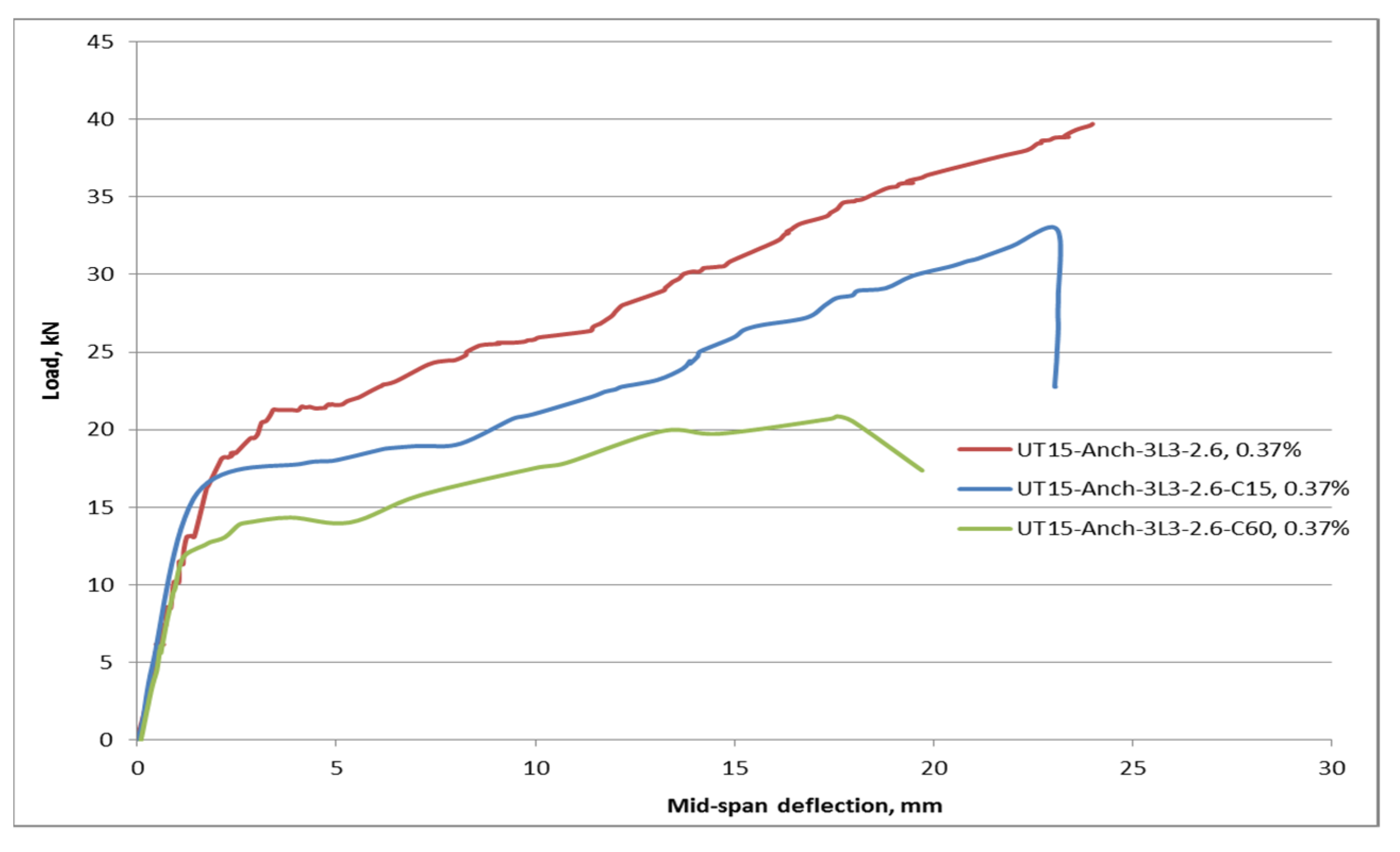
Corrosion resistance can be considered one of the main benefits of textiles in TRC beams, which can be the reason for lower cover thickness. This decrease in thickness may be advantageous in terms of reduced concrete usage and, as a result, lower construction costs. As a result, the influence of cover thickness variation on TRC beam flexural performance was examined. Table 11 shows the results of the experimental test on TRC beams with various cover thicknesses. C15 and C60 denote cover thicknesses of 15 mm and 60 mm, respectively. Figure 20 shows the reinforcement details and cover thickness of different TRC beams. UT15-Anch-3L3-2.6 has a 30 mm cover thickness. As can be observed from the table, raising or reducing the cover thickness has a negative impact on load-bearing capacity.
The ultimate flexural load of the UT15-Anch-3L3-2.6-C15 beam with 15 mm cover was 17% lower than that of the UT15-Anch-3L3-2.6 beam with 30 mm cover thickness was with the same layout geometries. The load capacity should theoretically increase because the effective depth has been increased to 167 mm rather than 152 mm. It could be due to a lack of appropriate bonding as a result of the thin cover. Due to the bond loss, the textiles cannot reach their ultimate tensile stresses [30]. The load capacity of the UT15-Anch-3L3-2.6-C60 with 60 mm cover was reduced by about 45% compared to that of the beam with 30 mm cover thickness. Because there is no bond issue concerning cover thickness, this finding could be explained by reducing the adequate depth reduces the reinforced beam’s load capacity.
The thickness of the concrete cover is also a factor in the initial crack, as seen in Figure 21. It was observed that the beams with higher cover thicknesses obtained the lowest first-crack loads. This outcome is likely related to the fact that a loaded beam’s tension zone is unreinforced 60 mm from the bottom. This signifies that as the concrete reaches the cracking moment, the cracking process continues till the cracks reach the textile reinforcements, where at this point, the loads are transferred to the reinforcements [31]. The early fracture load of a 15 mm thin cover is lower than 30 mm but greater than 60 mm. The weaker bond owing to the smaller cover thickness could be explained by the observed drop in the first breaking load.
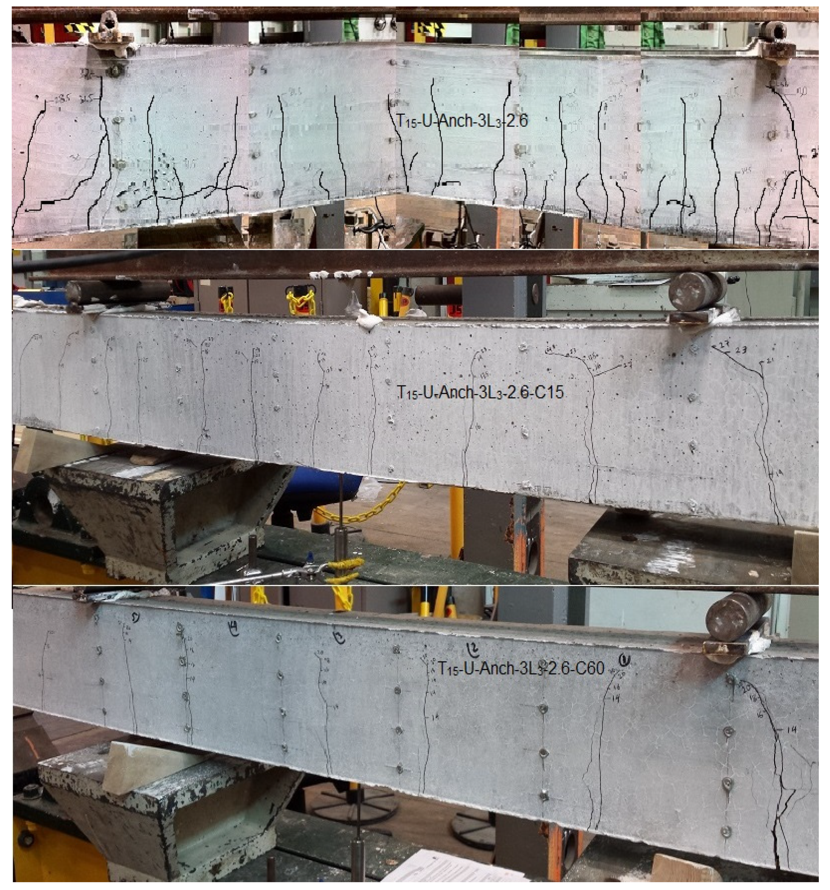
The number and width of cracks formed are also affected by the thickness of the cover. The crack patterns of UT15-Anch-3L3-2.6-C60 and UT15-Anch-3L3-2.6-C15 TRC beams are shown in Figure 22. It can be observed that the beams with 15 mm cover have about nine major cracks, while in the beams with a cover of 60 mm, the number of cracks was 6, which was comparatively lower than 13 for the beams with the cover of 30 mm. The lower quantity of cracks indicates a good bond between the textiles and concrete. However, it was noted that with the rise in the cover thickness, the width of cracks increased. Accordingly, based on the obtained results and the observations made, the TRC beams with 30 mm were performed better, and therefore 30 mm concrete cover thickness could be the optimum value for TRC beams. This optimum cover in TRC beams provides the appropriate and necessary bond to permit textile reinforcements to maximise the tensile stress utilisation, resulting in higher resistance against applied loads and sufficient flexural strength [32].
Concrete’s tensile strength is roughly 10% of its compressive strength. The concrete’s low tensile strength usually causes cracking [33]. Crack spacing in reinforced concrete spanning elements is influenced by several factors: member thickness or depth, reinforcement ratio, cover thickness, and bond strength [34]. The distance between cracks in TRC and SRC beams was tested experimentally. The crack pattern created in the steel-reinforced concrete is 10 initial cracks, stabilised at an applied load of 20 kN within the constant moment zone, as shown in Figure 15 and Figure 22, with an average crack spacing of 11.3 cm and a range of 6 to 15 cm. At roughly 85% of ultimate load and 20% of ultimate deflection, cracking has totally stabilised. Furthermore, the TRC beam test showed a crack pattern consisting of 13 primary cracks stabilised at a load of 26 kN, with an average crack spacing of 9 cm and a range of 6 cm to 15 cm. At roughly 70% of ultimate load and 30% of ultimate deflection, it is entirely stabilised. Furthermore, the TRC beam is distinguished from the SRC beam in terms of tiny cracks.
In comparison to the steel-reinforced beam, the TRC has a lot of small and horizontal cracks. The horizontal cracks can be explained by the horizontal cover thickness of 10 mm; thus, these cracks appear to be secondary/bond cracks. The additional cracks in the TRC beams are intriguing because they imply that the bond stress between the fibres and the concrete can develop faster than the bond stress between steel and concrete. This level of improvement in the bond was possibly unexpected, given that previous indicators showed that the fibres would have a lower bond/contamination with the concrete. Because of the configuration of the fibres within the beam cross-section in these large beam experiments, the situation may be improved [35].
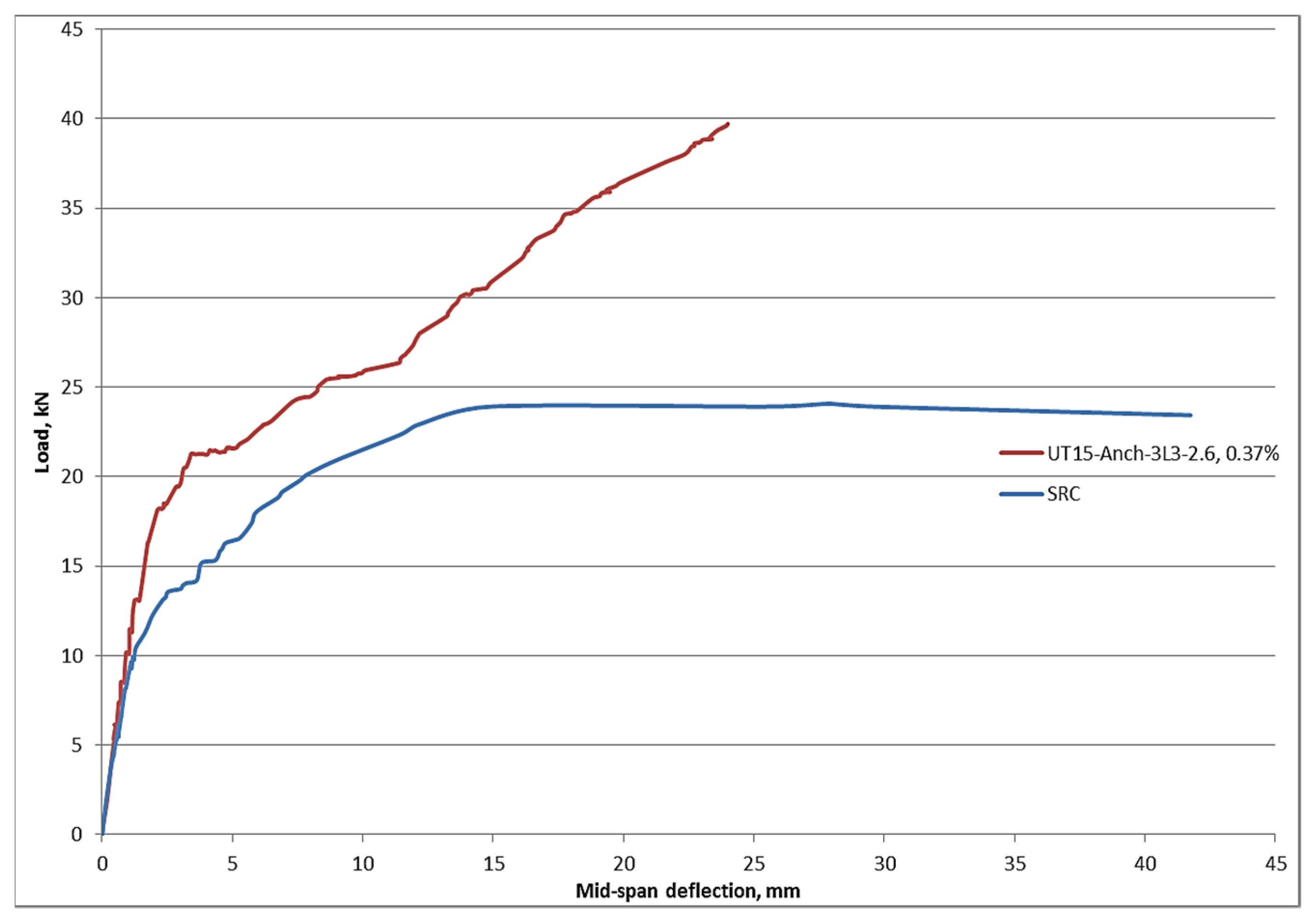
The load-deflection behaviours of large-scale UT15-Anch-3L3-2.6 and SRC beams are compared in Figure 23. Carbon textiles and steel bars were used as uni-axial reinforcement in the beams. The reinforcing area was nearly identical. The ultimate flexural load capacity of the carbon-tow-reinforced concrete beam is significantly greater than that of the steel-reinforced beam, as can be observed. The UT15-Anch-3L3-2.6 beam has a 60% higher strength capability than the SRC beam. Furthermore, the TRC beam has a greater rigidity than the SRC beam. The steel-reinforced beam is more plastic after cracking formation, as seen in the figure. The ultimate deflection of the UT15-Anch-3L3-2.6 beam is 40% smaller than that of the SRC beam. This is owing to the steel reinforcement’s yielding deformation [36,37]. According to the diagram, after reaching yielding strength, the ultimate steel reinforcement strength remains constant until the failure point is reached, regulated by the steel’s ultimate strain. Meanwhile, after all of the primary cracks occurred, the carbon-reinforced beam’s strength continues to increase until it reaches the failure point, which is regulated by the final strain of the textile reinforcement. The TRC beam, on the other hand, has a lower deflection at service loads than the SRC beam [38]. Although both beams have the same slope at service loads, the TRC beam deflects roughly 50% less than the SRC beam.

5. Conclusions

The efficiency of TRC vs. SRC in improving the flexural performance of full-scale concrete beams was investigated in this study. The impacts of several parameters such as the number of layers and cross-section area of textiles, the geometries, and the end anchorage system of textiles on the ultimate load and deflection were evaluated. The following are the key conclusions gained from this research:
  • Carbon textile reinforcing geometry and layout in TRC could have a detrimental or positive impact on its performance. Layering reinforcement improves load capacity by expanding the contact area.
  • Due to the prevention in the slipping of reinforcement, anchoring activates different filaments to resist the load.
  • By comparing different types of textiles, it was found that tow reinforcement has greater ultimate loads due to the higher bond strength between fabrics and concrete matrices.
  • Textile reinforcements are corrosion-resistant, allowing for thinner cover thicknesses to be designed. However, because of the lower ability for stress transmission amongst the reinforcements and concrete matrix, a thin cover might cause horizontal shear failure. In this study, the ideal cover thickness was determined to be 30 mm.
  • The surface interaction amongst the textile fibres and the concrete matrix is critical. In TRC beams, the toughness was improved by increasing the contact surface area. Consequently, the initial cracks in a TRC beam occur at a stress level 14% of that in corresponding SRC samples.
  • In TRC beams, the ultimate loads were increased by about 56% compared to those of SRC beams. In addition, the maximum mid-span deflection was around 37% lower than that of SRC beams. TRC beams have a substantially smaller deflection (62%) than SRC beams at Service Limit State.

Funding

This research was funded by of the Researchers Supporting Project number (RSP-2021/290), King Saud University, Riyadh, Saudi Arabia.

Institutional Review Board Statement

Not applicable.

Informed Consent Statement

Not applicable.

Data Availability Statement

The data presented in this study are available on request from the corresponding author. The data are not publicly available due to the size of the research.

Acknowledgments

The author gratefully acknowledges the financial support of the Researchers Supporting Project number (RSP-2021/290), King Saud University, Riyadh, Saudi Arabia.

Conflicts of Interest

The authors declare no conflict of interest.

References

  1. Wu, H.; Lin, X.; Zhou, A. A review of mechanical properties of fibre reinforced concrete at elevated temperatures. Cem. Concr. Res. 2020, 135, 106117. [Google Scholar] [CrossRef]
  2. Alrshoudi, F.; Mohammadhosseini, H.; Alyousef, R.; Alghamdi, H.; Alharbi, Y.R.; Alsaif, A. Sustainable use of waste poly-propylene fibers and palm oil fuel ash in the production of novel prepacked aggregate fiber-reinforced concrete. Sustainability 2020, 12, 4871. [Google Scholar] [CrossRef]
  3. Shi, F.; Pham, T.M.; Hao, H.; Hao, Y. Post-cracking behaviour of basalt and macro polypropylene hybrid fibre reinforced concrete with different compressive strengths. Constr. Build. Mater. 2020, 262, 120108. [Google Scholar] [CrossRef]
  4. Mohammadhosseini, H.; Awal, A.A.; Yatim, J.B.M. The impact resistance and mechanical properties of concrete reinforced with waste polypropylene carpet fibres. Constr. Build. Mater. 2017, 143, 147–157. [Google Scholar] [CrossRef]
  5. Raoof, S.M.; Koutas, L.N.; Bournas, D.A. Textile-reinforced mortar (TRM) versus fibre-reinforced polymers (FRP) in flexural strengthening of RC beams. Constr. Build. Mater. 2017, 151, 279–291. [Google Scholar] [CrossRef]
  6. Koutas, L.N.; Bournas, D.A. Flexural strengthening of two-way RC slabs with textile-reinforced mortar: Experimental investigation and design equations. J. Compos. Constr. 2017, 21, 04016065. [Google Scholar] [CrossRef]
  7. Tetta, Z.C.; Koutas, L.N.; Bournas, D.A. Shear strengthening of full-scale RC T-beams using textile-reinforced mortar and textile-based anchors. Compos. Part B Eng. 2016, 95, 225–239. [Google Scholar] [CrossRef]
  8. Raoof, S.M.; Bournas, D.A. Bond between TRM versus FRP composites and concrete at high temperatures. Compos. Part B Eng. 2017, 127, 150–165. [Google Scholar] [CrossRef]
  9. Loreto, G.; Babaeidarabad, S.; Leardini, L.; Nanni, A. RC beams shear-strengthened with fabric-reinforced-cementitious-matrix (FRCM) composite. Int. J. Adv. Struct. Eng. (IJASE) 2015, 7, 341–352. [Google Scholar] [CrossRef] [Green Version]
  10. Koutas, L.N.; Tetta, Z.; Bournas, D.A.; Triantafillou, T.C. Strengthening of concrete structures with textile reinforced mortars: State-of-the-art review. J. Compos. Constr. 2019, 23, 03118001. [Google Scholar] [CrossRef]
  11. Mohammadhosseini, H.; Alrshoudi, F.; Tahir, M.M.; Alyousef, R.; Alghamdi, H.; Alharbi, Y.R.; Alsaif, A. Durability and thermal properties of prepacked aggregate concrete reinforced with waste polypropylene fibers. J. Build. Eng. 2020, 32, 101723. [Google Scholar] [CrossRef]
  12. Mohammadhosseini, H.; Alyousef, R.; Poi Ngian, S.; Tahir, M.M. Performance Evaluation of Sustainable Concrete Comprising Waste Polypropylene Food Tray Fibers and Palm Oil Fuel Ash Exposed to Sulfate and Acid Attacks. Crystals 2021, 11, 966. [Google Scholar] [CrossRef]
  13. Ortlepp, R.; Ortlepp, S. Textile reinforced concrete for strengthening of RC columns: A contribution to resource conservation through the preservation of structures. Constr. Build. Mater. 2017, 132, 150–160. [Google Scholar] [CrossRef]
  14. Alrshoudi, F.; Mohammadhosseini, H.; Alyousef, R.; Alabduljabbar, H.; Mustafa Mohamed, A. The impact resistance and deformation performance of novel pre-packed aggregate concrete reinforced with waste polypropylene fibres. Crystals 2020, 10, 788. [Google Scholar] [CrossRef]
  15. Papanicolaou, C.G.; Papantoniou, I.C. Mechanical behavior of textile reinforced concrete (TRC)/concrete composite elements. J. Adv. Concr. Technol. 2010, 8, 35–47. [Google Scholar] [CrossRef] [Green Version]
  16. Tysmans, T.; Adriaenssens, S.; Cuypers, H.; Wastiels, J. Structural analysis of small span textile reinforced concrete shells with double curvature. Compos. Sci. Technol. 2009, 69, 1790–1796. [Google Scholar] [CrossRef]
  17. Verbruggen, S.; Aggelis, D.G.; Tysmans, T.; Wastiels, J. Bending of beams externally reinforced with TRC and CFRP monitored by DIC and AE. Compos. Struct. 2014, 112, 113–121. [Google Scholar] [CrossRef]
  18. Mobasher, B. Mechanics of Fiber and Textile Reinforced Cement Composites; CRC Press: Boca Raton, FL, USA, 2011. [Google Scholar]
  19. Cuypers, H.; Wastiels, J. Stochastic matrix-cracking model for textile reinforced cementitious composites under tensile loading. Mater. Struct. 2006, 39, 777–786. [Google Scholar] [CrossRef]
  20. Banholzer, B.; Brockmann, T.; Brameshuber, W. Material and bonding characteristics for dimensioning and modelling of textile reinforced concrete (TRC) elements. Mater. Struct. 2006, 39, 749–763. [Google Scholar] [CrossRef]
  21. Brockmann, T. Mechanical and fracture mechanical properties of fine grained concrete for TRC structures. In Advances in Construction Materials; Springer: Berlin/Heidelberg, Germany, 2007; pp. 119–129. [Google Scholar]
  22. Contamine, R.; Larbi, A.S.; Hamelin, P. Contribution to direct tensile testing of textile reinforced concrete (TRC) composites. Mater. Sci. Eng. A 2011, 528, 8589–8598. [Google Scholar] [CrossRef]
  23. Contamine, R.; Larbi, A.S.; Hamelin, P. Identifying the contributing mechanisms of textile reinforced concrete (TRC) in the case of shear repairing damaged and reinforced concrete beams. Eng. Struct. 2013, 46, 447–458. [Google Scholar] [CrossRef]
  24. Tsesarsky, M.; Peled, A.; Katz, A.; Anteby, I. Strengthening concrete elements by confinement within textile reinforced concrete (TRC) shells–Static and impact properties. Constr. Build. Mater. 2013, 44, 514–523. [Google Scholar] [CrossRef]
  25. Shams, A.; Horstmann, M.; Hegger, J. Experimental investigations on Textile-Reinforced Concrete (TRC) sandwich sections. Compos. Struct. 2014, 118, 643–653. [Google Scholar] [CrossRef]
  26. Brückner, A.; Ortlepp, R.; Curbach, M. Anchoring of shear strengthening for T-beams made of textile reinforced concrete (TRC). Mater. Struct. 2008, 41, 407–418. [Google Scholar] [CrossRef]
  27. Portal, N.W.; Flansbjer, M.; Zandi, K.; Wlasak, L.; Malaga, K. Bending behaviour of novel Textile Reinforced Concrete-foamed concrete (TRC-FC) sandwich elements. Compos. Struct. 2017, 177, 104–118. [Google Scholar] [CrossRef]
  28. Kong, K.; Mesticou, Z.; Michel, M.; Larbi, A.S.; Junes, A. Comparative characterisation of the durability behaviour of textile-reinforced concrete (TRC) under tension and bending. Compos. Struct. 2017, 179, 107–123. [Google Scholar] [CrossRef]
  29. Douk, N.; Vu, X.H.; Larbi, A.S.; Audebert, M.; Chatelin, R. Numerical study of thermomechanical behaviour of reinforced concrete beams with and without textile reinforced concrete (TRC) strengthening: Effects of TRC thickness and thermal loading rate. Eng. Struct. 2021, 231, 111737. [Google Scholar] [CrossRef]
  30. Li, T.; Deng, M.; Jin, M.; Dong, Z.; Zhang, Y. Performance of axially loaded masonry columns confined using textile reinforced concrete (TRC) added with short fibers. Constr. Build. Mater. 2021, 279, 122413. [Google Scholar] [CrossRef]
  31. Colombo, I.G.; Magri, A.; Zani, G.; Colombo, M.; Di Prisco, M. Erratum to: Textile Reinforced Concrete: Experimental investigation on design parameters. Mater. Struct. 2013, 46, 1953–1971. [Google Scholar] [CrossRef] [Green Version]
  32. Alaskar, A.; Alqarni, A.S.; Alfalah, G.; El-Sayed, A.K.; Mohammadhosseini, H.; Alyousef, R. Performance evaluation of reinforced concrete beams with corroded web reinforcement: Experimental and theoretical study. J. Build. Eng. 2021, 35, 102038. [Google Scholar] [CrossRef]
  33. Mohammadhosseini, H.; Ngian, S.P.; Alyousef, R.; Tahir, M.M. Synergistic effects of waste plastic food tray as low-cost fibrous materials and palm oil fuel ash on transport properties and drying shrinkage of concrete. J. Build. Eng. 2021, 102826. [Google Scholar] [CrossRef]
  34. Mohammadhosseini, H.; Alyousef, R. Towards Sustainable Concrete Composites through Waste Valorisation of Plastic Food Trays as Low-Cost Fibrous Materials. Sustainability 2021, 13, 2073. [Google Scholar] [CrossRef]
  35. Tahir, M.M.; Mohammadhosseini, H.; Ngian, S.P.; Effendi, M.K. I-beam to square hollow column blind bolted moment connection: Experimental and numerical study. J. Constr. St. Res. 2018, 148, 383–398. [Google Scholar] [CrossRef]
  36. Mohammadhosseini, h.; Awal, A.S.M.A. Physical and mechanical properties of concrete containing fibers from industrial carpet waste. Int. J. Res. Eng. Technol. 2013, 2(12), 464–468. [Google Scholar]
  37. Alrshoudi, F.; Mohammadhosseini, H.; Tahir, M.M.; Alyousef, R.; Alghamdi, H.; Alharbi, Y.; Alsaif, A. Drying shrinkage and creep properties of prepacked aggregate concrete reinforced with waste polypropylene fibers. J. Build. Eng. 2020, 32, 101522. [Google Scholar] [CrossRef]
  38. Tahir, M.M.; Mohammadhosseini, H.; Alyousef, R.; Leong, W.K.; Salih, M.N. Performance Evaluation of Pre-fabricated footing using cold-formed steel of lipped c-channel section. Arab. J. Scie. Eng. 2019, 44, 8225–8238. [Google Scholar] [CrossRef]
Figure 1. Multi-filament carbon fibres used as reinforcement of TRC beams.
Crystals 11 01272 g001
Figure 2. Four-point bending test set-up used for large-scale beams.
Crystals 11 01272 g002
Figure 3. The arrangement of demecs on the surface of beams.
Crystals 11 01272 g003
Figure 4. The arrangement of textile fibres in bi-axial TRC beams.
Crystals 11 01272 g004
Figure 5. Different layers of textiles in uni-axial TRC beams; (a) 4UT8-S-2.6, (b) 4UT8-S-L-2.6.
Crystals 11 01272 g005
Figure 6. The arrangement of textile layouts in uni-axial TRC beams; (a) 3UT12 or 15-Anch-L3-2.6, (b) 3UT15-Anch-L3-2.6-C15.
Crystals 11 01272 g006
Figure 7. Details of reinforcement arrangement in SRC beams.
Crystals 11 01272 g007
Figure 8. Mid-span load-deflection of large-scale bi-axial TRC beams.
Crystals 11 01272 g008
Figure 9. The failure mode and cracks pattern of BT(5cm)14-Anch-2.6-L, 50k TRC beam.
Crystals 11 01272 g009
Figure 10. Mid-span load-deflection of straight end tow uni-axial TRC beams at different layers.
Crystals 11 01272 g010
Figure 11. The failure modes and cracks pattern of (a) UT8-2.6, 50km and (b) UT8 -L-2.6, 50k, TRC beams.
Crystals 11 01272 g011aCrystals 11 01272 g011b
Figure 12. Mid-span load-deflection of anchored end uni-axial TRC beams.
Crystals 11 01272 g012
Figure 13. The mods of failure and crack patterns of uni-axial TRC beams.
Crystals 11 01272 g013
Figure 14. Mid-span load-deflection of the SRC beam.
Crystals 11 01272 g014
Figure 15. The failure mode and crack pattern of SRC beam.
Crystals 11 01272 g015
Figure 16. Details of reinforcements in straight and anchored end TRC beams.
Crystals 11 01272 g016
Figure 17. Details of reinforcements of UT8-Anch-2.6 and UT12-Anch-3L3-2.6 TRC beams.
Crystals 11 01272 g017
Figure 18. Details of reinforcements in (a) UT12-Anch-3L3-2.6 and (b) UT15-Anch-3L3-2.6 TRC beams.
Crystals 11 01272 g018
Figure 19. Mid-span load-deflection of UT15-Anch-3L3-2.6 and UT12-Anch-3L3-2.6 TRC beams.
Crystals 11 01272 g019
Figure 20. Details of different cover thicknesses in (a) UT15-Anch-3L3-2.6 (b) UT15-Anch-3L3-2.6-C15 and (c) UT15-Anch-3L3-2.6-C60 TRC beams.
Crystals 11 01272 g020
Figure 21. Effects of cover thickness on the mid-span load-deflection of TRC beams.
Crystals 11 01272 g021
Figure 22. The failure modes and crack patterns of TRC beams with various covers.
Crystals 11 01272 g022
Figure 23. Load-deflection behaviour at mid-span of uni-axial reinforcement (tow) and steel-reinforced concrete beams.
Crystals 11 01272 g023
Table 1. Engineering properties of carbon textile reinforcements.
PropertiesTow, 50k
No. of filaments (k)50
Filament diameter (µm)7
Fabric weight (g/m2)130
Modulus of elasticity, E f (MPa)235,000
Tensile strength, ff (MPa)4000
Table 2. The mixed proportions of plain concrete.
Concrete MixtureMix (kg/m3)
Cement504
Coarse aggregates1108
Sand683
Water177
w/c0.35
Superplasticizer (SP), Litre7
Slump Test (mm)110
Compressive Strength (MPa)85
Table 3. Characteristics of tested beams.
ReinforcementEffective Area (mm2)Vf (%)Cover Thickness (mm)No. of TowsNo. of Tow LevelsNo. of WarpsEnds of TextilesUltimate Load (kN)Deflection (mm)
BT(5cm)14-Anch-2.6, 50k80.70.5730-13Anchored11.814.5
UT8-2.6, 50k61.50.2530814Straight13.89.0
UT8-L-2.6, 50k61.50.2530824Straight14.415.7
UT8-Anch-2.6, 50k61.50.2530814Anchored16.411
UT8-Anch-L-2.6, 50k61.50.2530824Anchored18.315.5
UT12-Anch-3L3-2.6, 50k61.50.25301234Anchored19.616
UT12-Anch-L-2.6, 50k92.30.37301224Anchored16.317
UT15-Anch-3L3-2.6, 50k92.30.37301533Anchored39.423.7
UT15-Anch-3L3-2.6, 50k92.30.37301533Anchored33.617.6
UT15-Anch-3L3-2.6-C1592.30.37151533Anchored32.622.6
UT15 -Anch-3L3-2.6-C6092.30.37601533Anchored21.416.6
SRC100.50.42302 Φ 8--Anchored24.540.5
Table 4. Results of bi-axial TRC beams.
ReinforcementEffective Area (mm2)Vf (%)Ultimate Load (kN)Deflection (mm)
BT(5cm)14-Anch-2.6, 50k80.70.5711.814.5
Table 5. Results of straight end tow uni-axial TRC beams.
ReinforcementEffective Area (mm2)Vf (%)Ultimate Load (kN)Deflection (mm)
UT8-2.6, 50k61.50.2513.89.0
UT8-L-2.6, 50k61.50.2514.415.7
Table 6. The effects of anchored end on the performance of uni-axial tow TRC beams.
ReinforcementEffective Area (mm2)Vf (%)Ultimate Load (kN)Deflection (mm)
UT8-Anch-2.6, 50k61.50.2516.411
UT8-Anch-L-2.6, 50k61.50.2518.315.5
UT12-Anch-3L3-2.6, 50k61.50.2519.616
UT12-Anch-L-2.6, 50k92.30.3716.317
UT15-Anch-3L3-2.6, 50k92.30.3739.423.7
UT15-Anch-3L3-2.6, 50k92.30.3733.617.6
UT15-Anch-3L3-2.6-C1592.30.3732.622.6
UT15 -Anch-3L3-2.6-C6092.30.3721.416.6
Table 7. Results of control SRC beam.
ReinforcementEffective Area (mm2)Vf (%)Ultimate Load (kN)Deflection (mm)
SRC100.50.4224.540.5
Table 8. Results of anchored and straight end TRC beams.
ReinforcementEffective Area (mm2)Vf (%)Ultimate Load (kN)Deflection (mm)
UT8-2.6, 50k61.50.2513.79
UT8-Anch-2.6, 50k61.50.2516.611
Table 9. Outcomes of TRC beams having the same cross-section area and various layers.
ReinforcementEffective Area (mm2)Vf (%)Ultimate Load (kN)Deflection (mm)
UT8-Anch-2.6, 50k61.50.2516.411
UT8-Anch-L-2.6, 50k61.50.2518.315.7
UT12-Anch-3L3-2.6, 50k61.50.2519.616.1
Table 10. Effects of the variation in cross-section area on the performance of TRC beams.
ReinforcementArea (mm2)Vf (%)Initial Crack Load (kN)Ultimate Load (kN)Deflection (mm)
UT12-Anch-3L3-2.6, 50k61.50.251419.616
UT15-Anch-3L3-2.6, 50k92.30.3717.639.223.5
Table 11. The effects of cover thicknesses on the performance of TRC beams.
ReinforcementEffective Area (mm2)Vf (%)Ultimate Load (kN)Deflection (mm)
UT15-Anch-3L3-2.6, 50k92.30.3739.423.5
UT15-Anch-3L3-2.6-C15, 50k92.30.3732.622.6
UT15-Anch-3L3-2.6-C60, 50k92.30.3721.416.8
Publisher’s Note: MDPI stays neutral with regard to jurisdictional claims in published maps and institutional affiliations.