1. Introduction
Construction of structures employing materials with improved physical performance and durability has become increasingly important in recent years; the new goal is to create structures that are more sustainable, durable, and require less maintenance. As a secondary reinforcement, discontinuous fibres have been used in the concrete to prevent cracking [
1,
2]. This technology cannot replace primary steel reinforcement. Carbon and glass fibres have been used in reinforced concrete (RC) structural elements for decades. It is important to note that these materials do not undergo corrosion in the traditional sense, allowing for advantages in structural design such as smaller cover dimensions and a thinner structural element [
3,
4].
Roving fibres have recently been researched as a primary reinforcing material to substitute steel bars in concrete components. To solve such shortcomings, a novel group of composite materials integrating high-strength textile fibres has been proposed as a structural component for weak RC parts, namely the textile-reinforced concrete (TRC) [
5]. TRC is a lower-cost alternative to traditional SRC, is harmless for workers, and is companionable with concrete and masonry matrices. Several research studies [
6,
7] have looked at the bonding effectiveness of TRC and concrete substrate. TRC has been used successfully in the building industry all around the world. With a limited number of textile layers, TRC has also been explored for flexural strength [
8,
9,
10]. The experimental results, on the other hand, confirm TRC’s usefulness as a structural member.
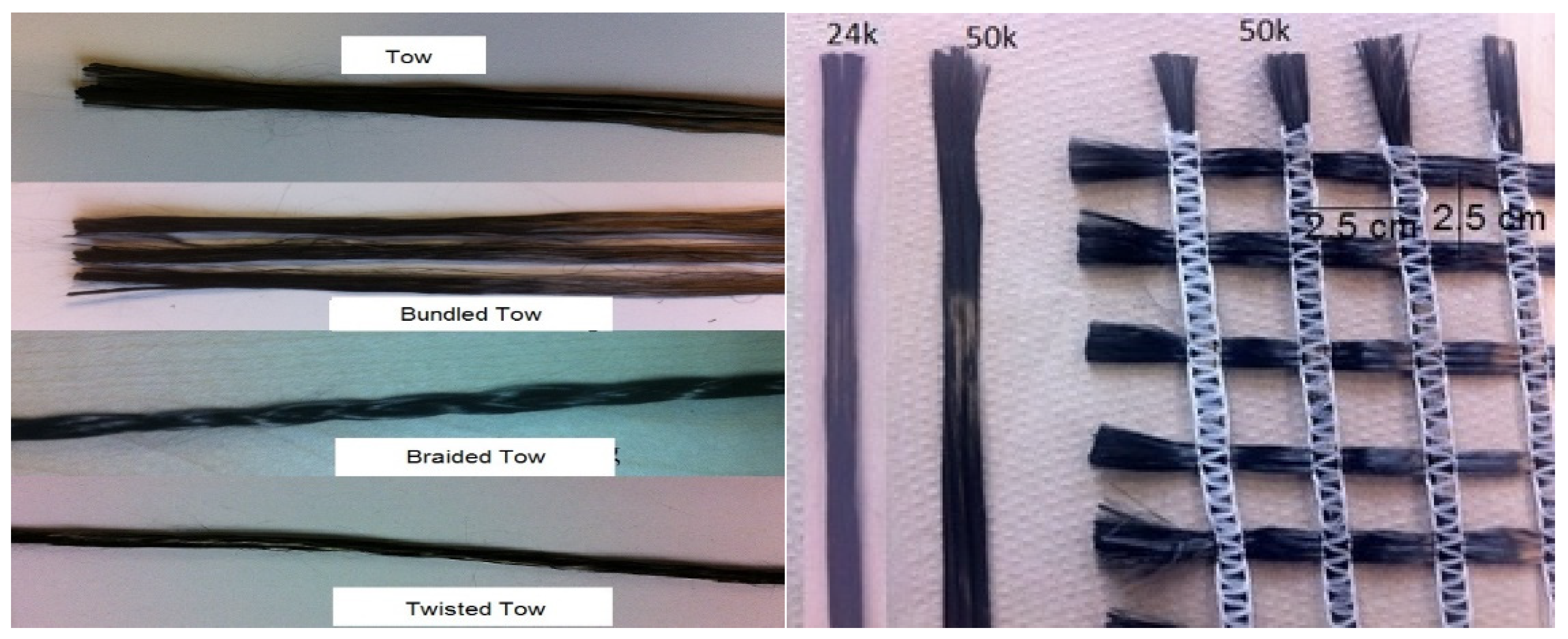
TRC is a material made up of fine-grained concrete and textile fibres. The textile material could be alkali-resistant multi-filament roving, and the concrete is usually built with a coarse aggregate size of 10 mm [
11,
12]. This combination produces a composite material with desirable characteristics, including higher tensile strength, better corrosion resistance, lighter weight, and thinner cover [
13,
14]. TRC’s components have significant benefits over FRC, which can be used in areas with high stress. According to Papanicolaou and Papantoniou [
15], the properties of TRC are entirely depend on whether it is placed in the desired location and in sufficient quantity, whereas typical fibres that are arbitrarily spread and directed are inefficient. Due to their random orientation, the fibres in FRC are not fully utilised in fracture management, strengthening, or stiffening. According to Tysmans et al. [
16], because textile reinforcement has high tensile strength, it might be employed as a major reinforcement instead of steel.
In addition, the existence of fibres does not affect the strength of a beam’s compression zone [
17]. TRC combines the benefits of short-fibre-reinforced concrete and conventional SRC. Furthermore, TRC has a substantially lower volume of fibres than FRC. More than 3% FRC is necessary for concrete to be reinforced adequately due to fibres’ lower required dosage and the increased fibre consumption efficiency [
18]. TRC will result in structures with cheaper costs [
19,
20,
21]. Given all of these advantages, a greater knowledge of these materials’ behaviours will enable them to be employed more effectively in composite materials and, as a result, will assist the building industry more. TRC’s behaviour needs to be better understood before it can be used reliably.
The existing literature does not fully address the comparison of the flexural performance of TRC and SRC beams when textile fibres are used as the primary reinforcement in various layouts. In addition, the flexural behaviour of TRC has not been thoroughly investigated, and more data are required before it can be safely used. Accordingly, the primary objective of this research work was to evaluate the effect of textile fibres as the main reinforcement on the flexural performance of full-scale TRC beams and investigate how the textile fibres contribute to the decrease in crack formation and deterioration in comparison to SRC beams. Along with flexural performance in terms of load-deflection behaviour, the performance of TRC beams for other parameters such as various anchored roving, fabrics’ cross-sectional area, textile fibre layering, textile geometries, and cover thicknesses were also investigated.
4. Discussion
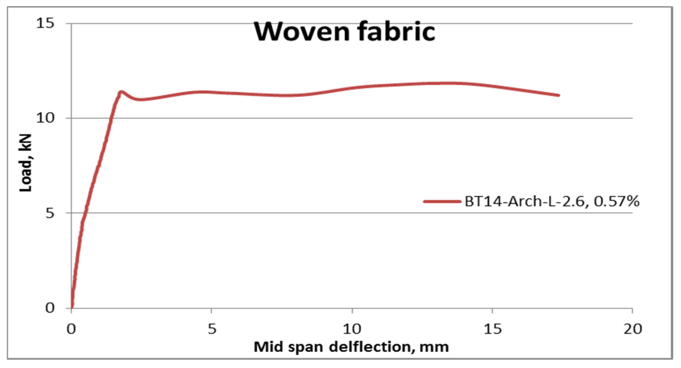
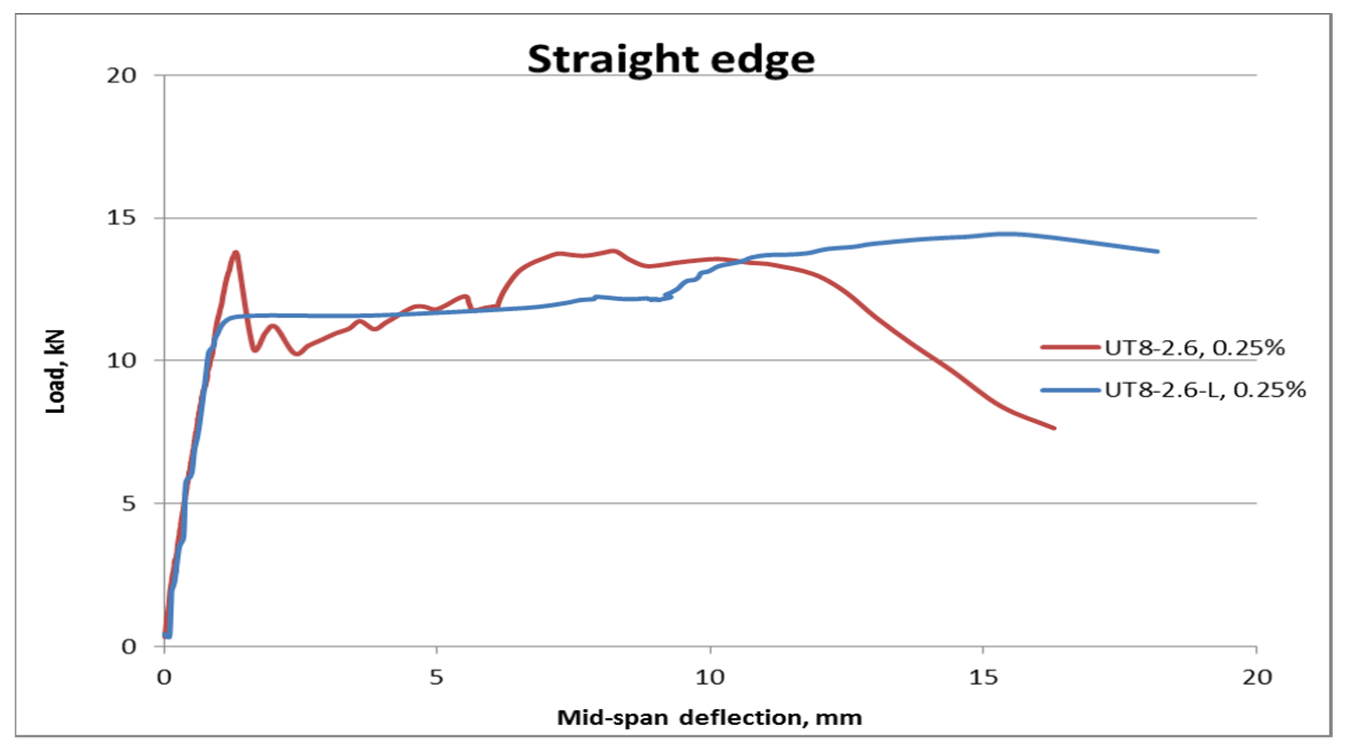
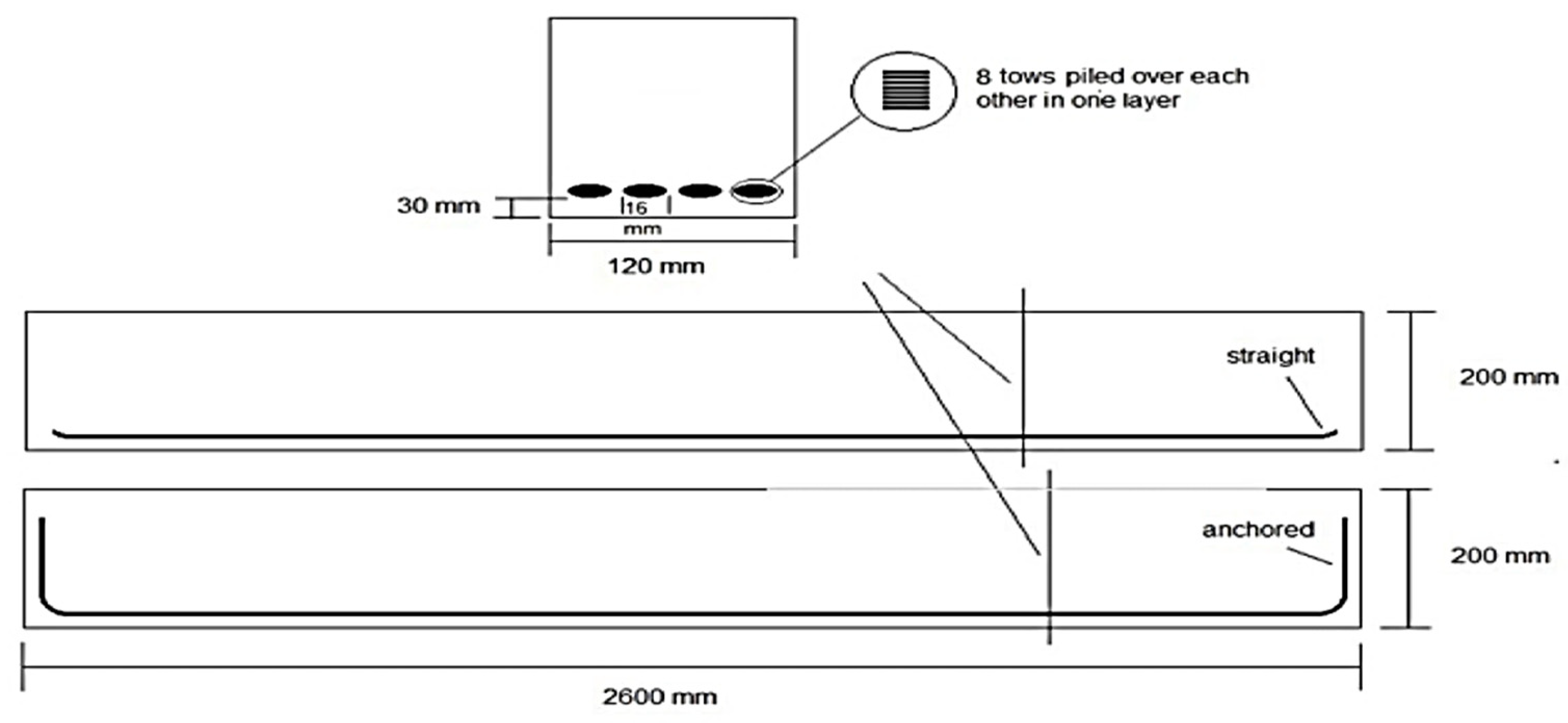
The impact of anchored roving on TRC beam performance was examined. The straight and anchored TRC beams were thus tested.
Table 8 displays the flexural performance of TRC beams with the same cross-section area and having straight and anchored end reinforcements.
Figure 16 shows the reinforcement details, with the reinforcement placed down in a single layer. It was found that the load capacity of UT
8-Anch-2.6 was raised due to anchoring the reinforcement. Compared to UT
8-2.6 with straight-end reinforcements, the load capacity of UT8-Anch-2.6 rose by about 24% to 16.5 kN. The outcome was expected because the tows were anchored, preventing the filaments from slipping freely [
22,
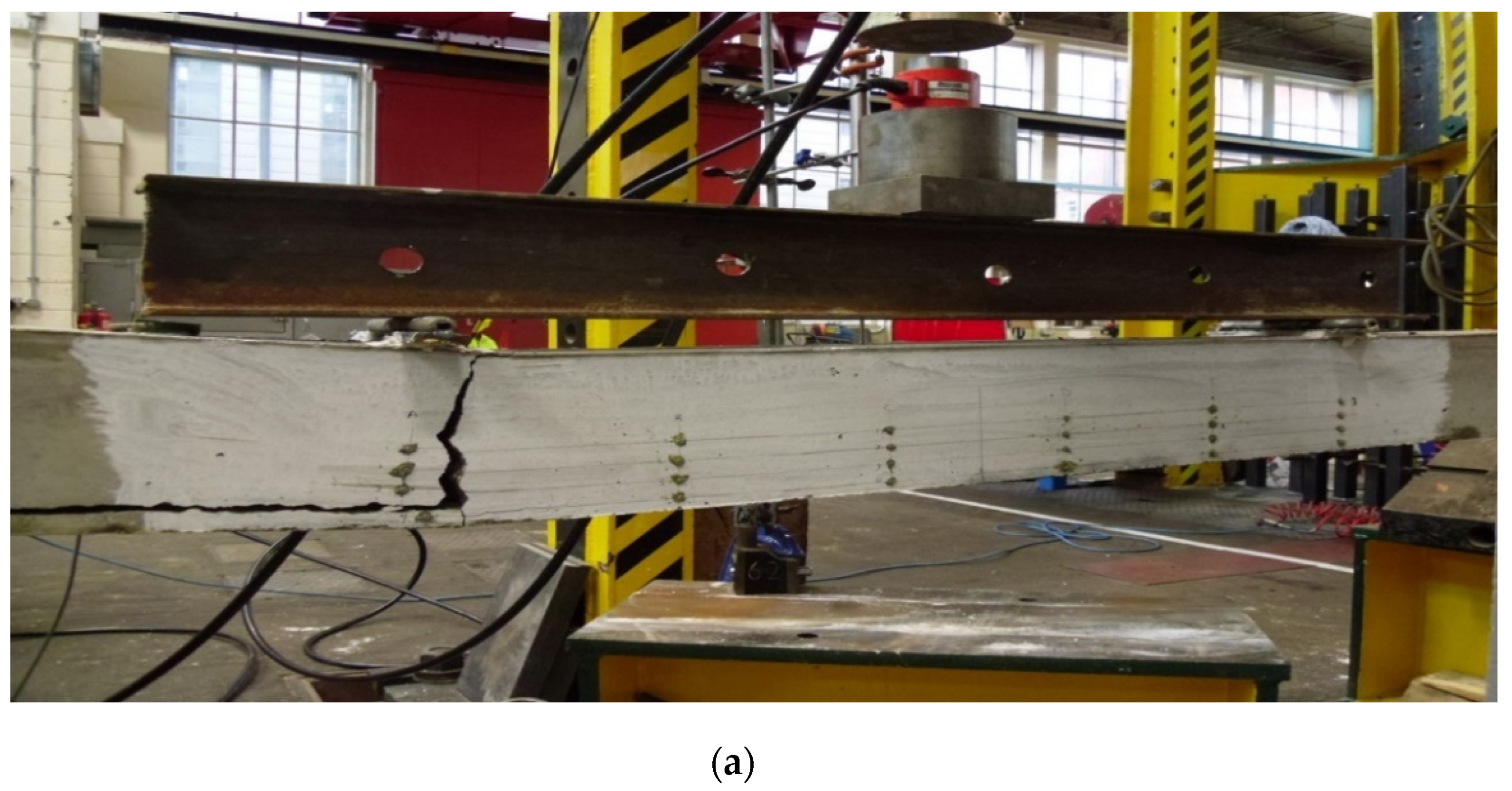
23]. The tows slipped in UT8-2.6 due to the flexural loading, causing the lengths to remain unchanged. The slickness was caused by the reinforcement’s straight end, which could not provide expansion length, the short interaction area amongst matrix and textile reinforcements. The delamination crack, which is the outcome of supporting the rovings on top of each other, dominates the crack behaviour.
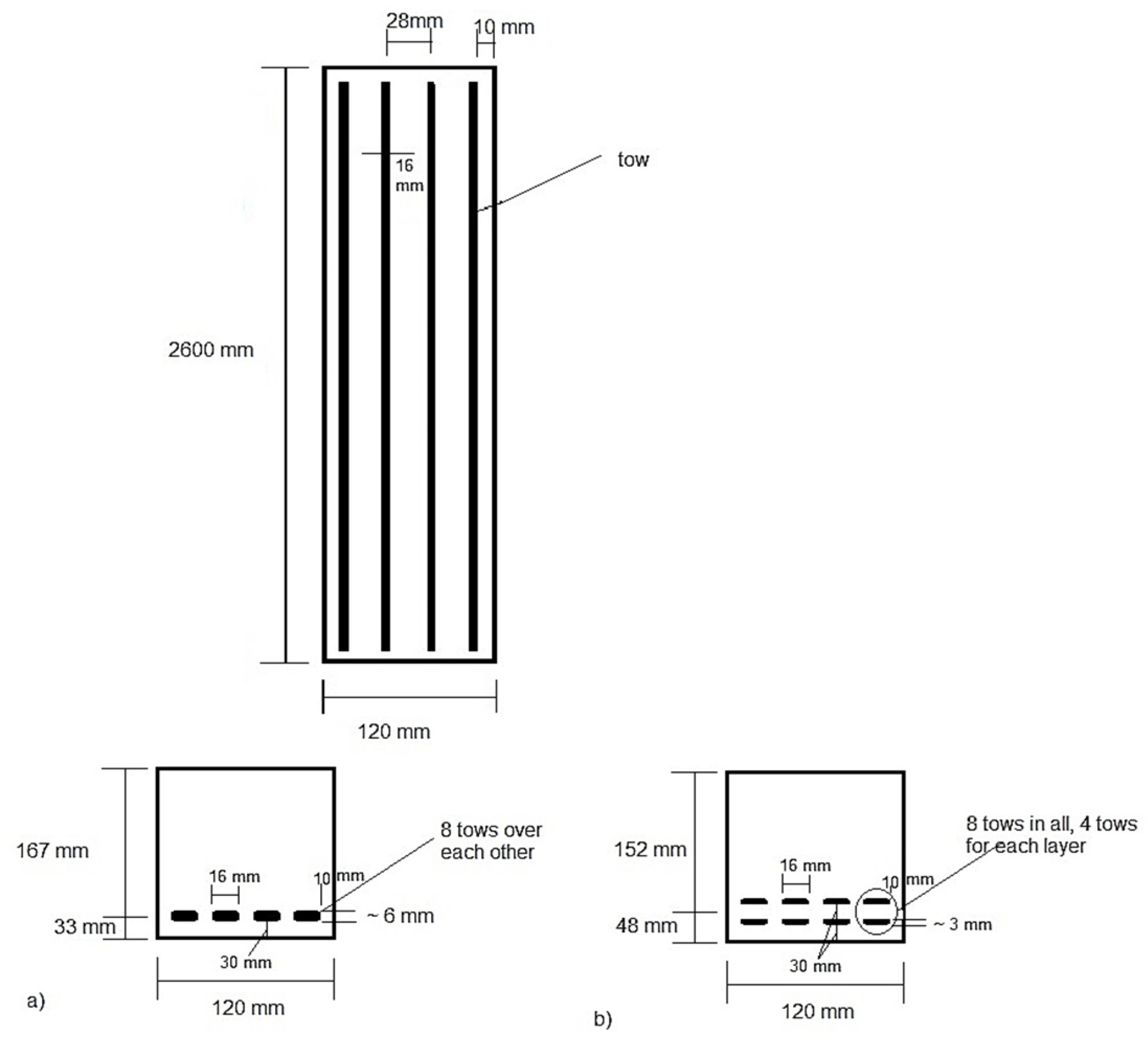
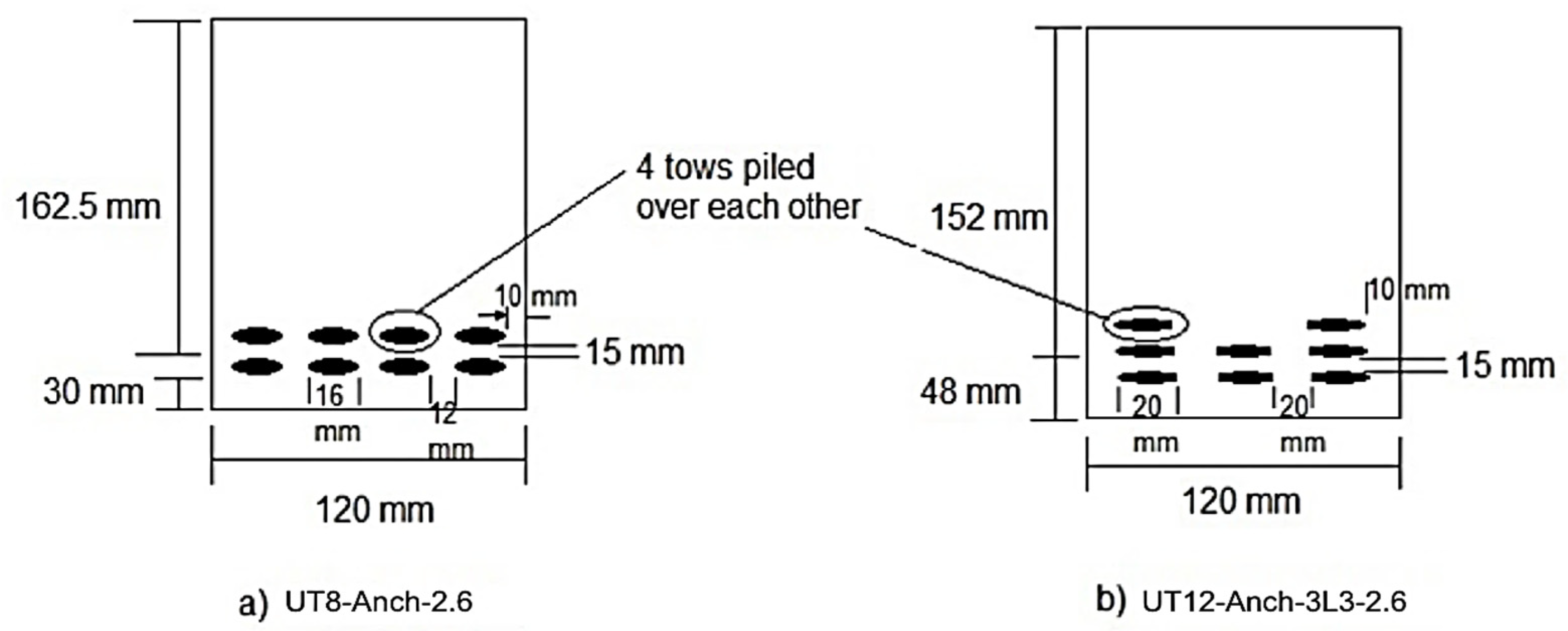
In addition, the influence of textile fibre layering on beam performance was examined. As previously stated, the UT
8-Anch-2.6 TRC beam failed quickly in the loading process since the tow textiles were stacked on top of each other, causing penetration issues and reducing the interaction area with the concrete matrix. Consequently, the tows were separated into two layers at a similar area, with four tows put over each other and four in horizontal uni-axial directions in each layer [
24]. Furthermore, the tow textiles were placed into three layers and three horizontal orientations, as shown in
Figure 17, to assess the consequence of layering on the performance of TRC beams, which will enhance the contact area and, therefore, the higher load-bearing capacity of beams. In the effective depth calculation, the thickness of the tows was considered insignificant. The load-bearing capability will theoretically decrease as the effective depth decreases [
25]. The experimental results revealed that layering and reforming reinforcement schemes increased the ultimate loads of TRC beams.
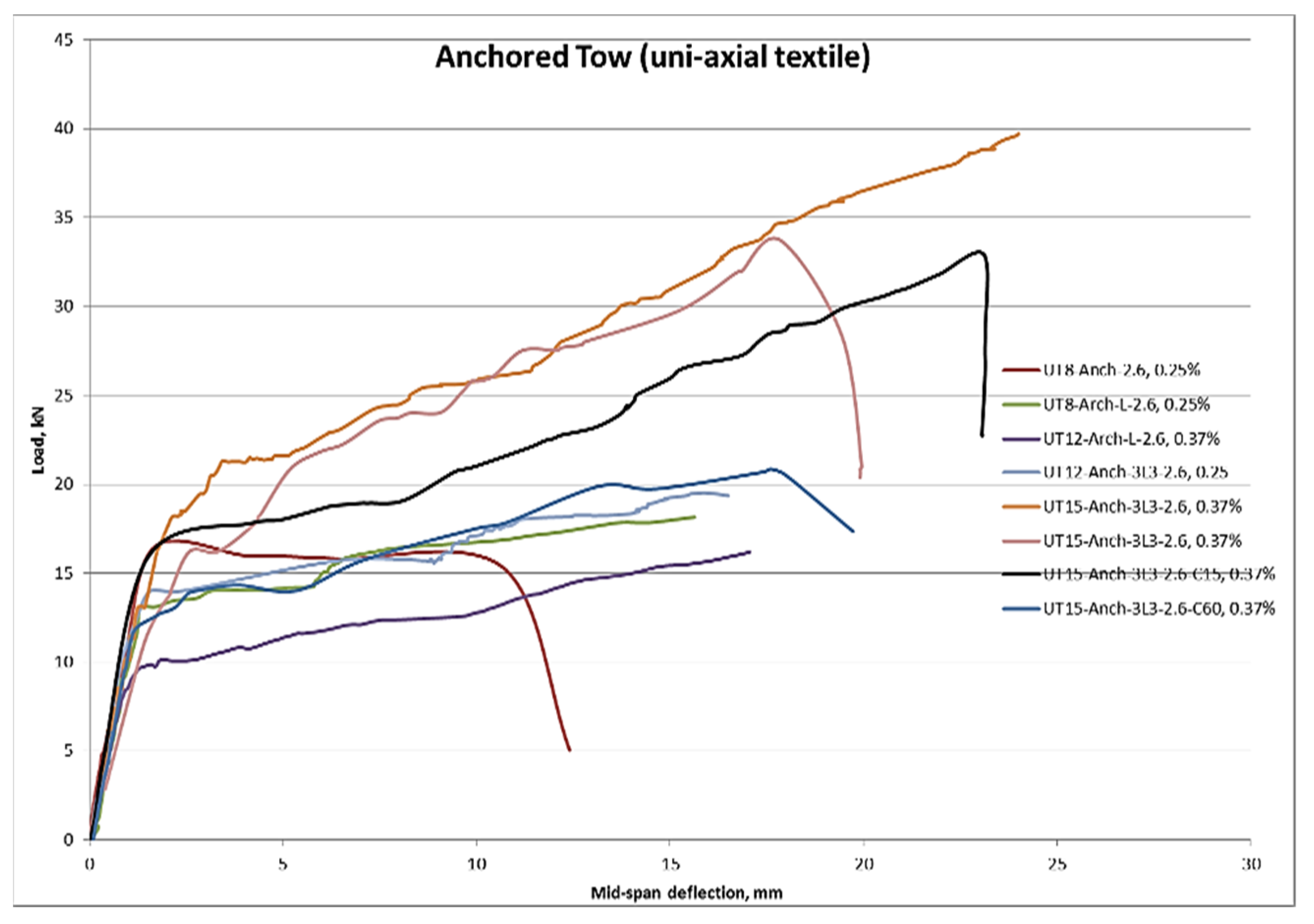
From
Table 9, it can be observed that the UT
12-Anch-3L
3-2.6 had the maximum load capacity. Compared to UT8-Anch-2.6, which is entirely anchored beams, it rose by about 18%, where UT
8-Anch-L-2.6 beam enhanced by about 10%. Because of the reinforcing layers, the ductility was also improved. Owing to the dividing of the textile tows into different layers, the bearing capacity was enhanced. However, the adequate depth was lowered due to the layering, and it resulted in the enhancement of beams owing to the rise in the contact area of fibres and concrete matrix [
26]. While tow reinforcement is divided into two or three layers, the number of exposed filaments that can contact the concrete increases, improving the bond, while the number of inner fibres decreases [
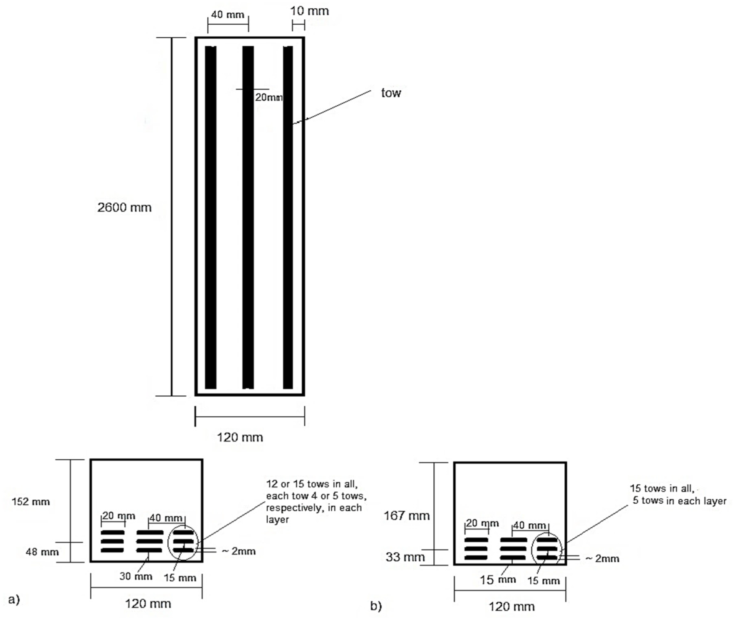
27]. In addition, by separating the tow reinforcements into three horizontal directions instead of four, the roving can be expanded to a width of 20 mm rather than 16 mm, as shown in
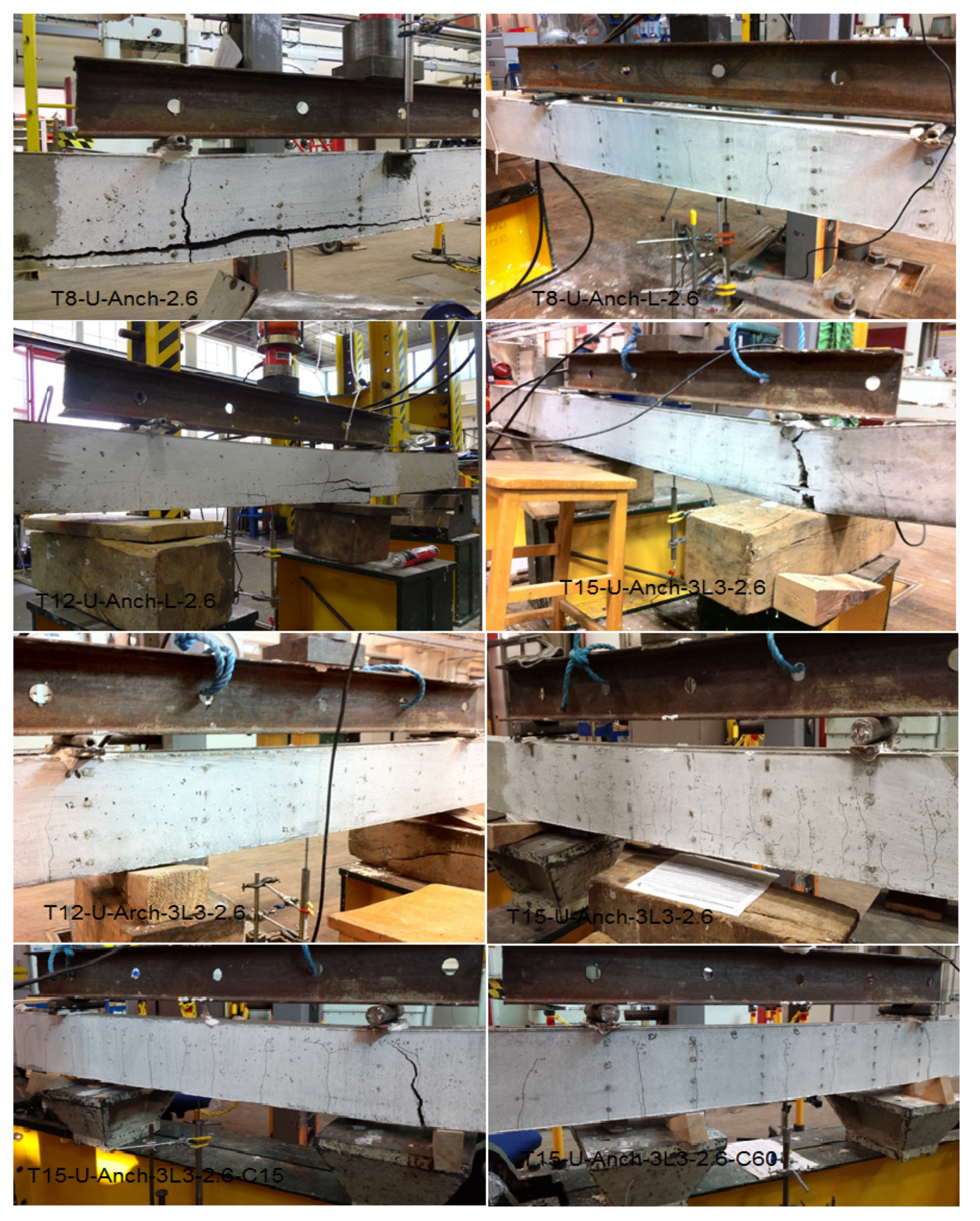
Figure 17. This enhanced the amount of exposed area that might interact with the concrete. As a result, the increased bond compensates for the projected drop in load capacity due to the reduced adequate depth. In addition, the failure mechanism for UT
8-Anch-2.6 and T
12-U-Anch-3L
3-2.6 TRC beams was modified from delamination to flexural failure. Furthermore, the number of cracks in UT
8-Anch-L-2.6 and UT
12-Anch-3L
3-2.6 grew to 4 and 5, respectively. This difference in crack formation indicates that improving the link between filaments and matrix is critical [
28].
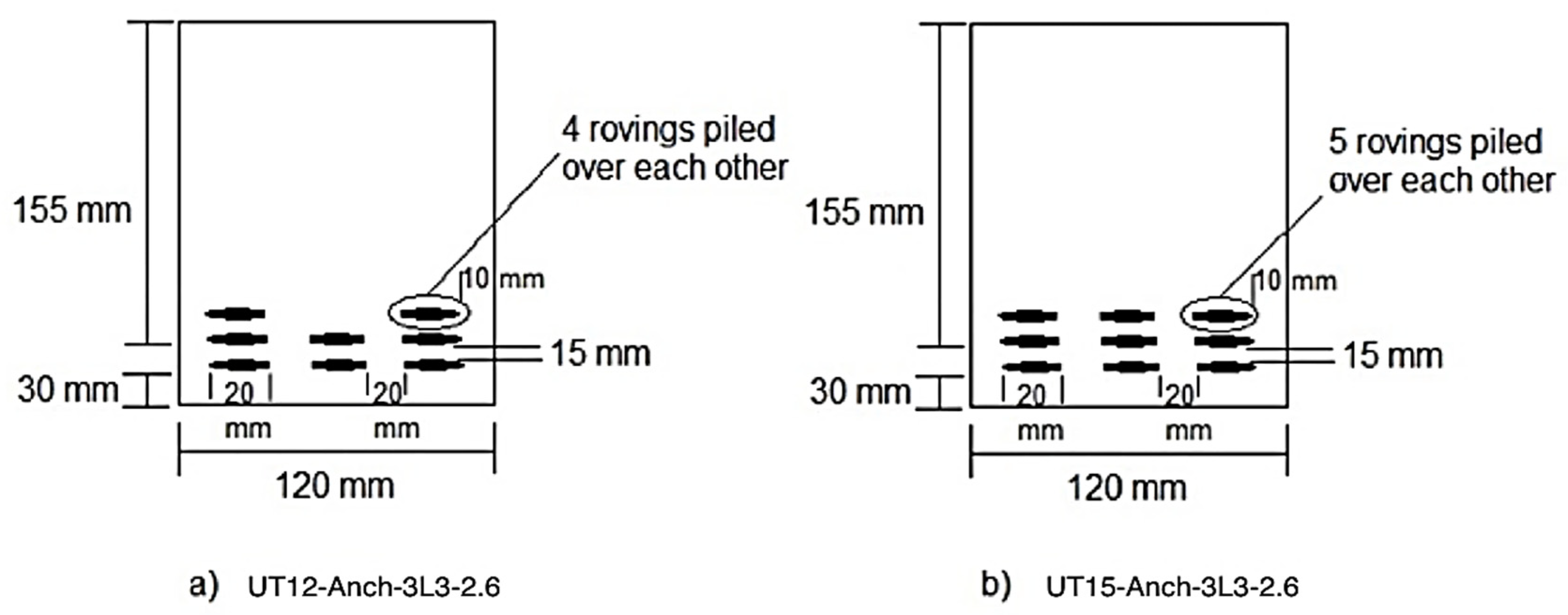
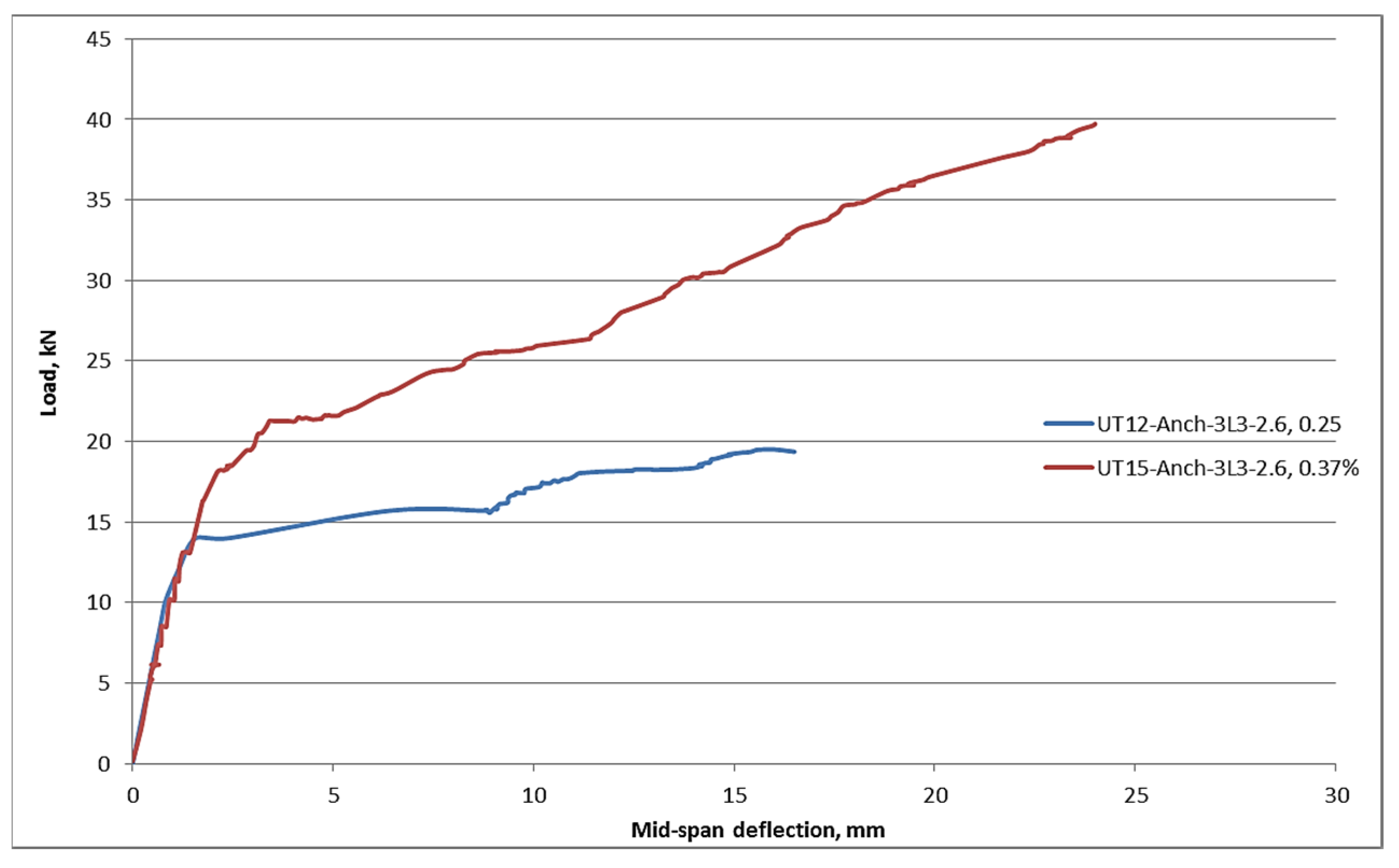
The influence of the fabrics’ cross-sectional area was also studied. The cross-section area of textiles fibres in the loading path was discovered to have a considerable impact on the behaviour of TRC beams.
Table 10 shows the outcomes of the experimental test. It was evident that raising the
Af improves the load-bearing capacity of TRC beams [
29]. It was noted that with the rise in cross-section area of textiles by 50%, the ultimate loads increased by about 100%, making it twice as much as the UT
12-Anch-3L
3-2.6 TRC beam. Therefore, due to this improvement in the load-bearing capacity, the beams’ performance was more ductile. The first crack load was 26% higher when the area was increased by 50%. Furthermore, the findings demonstrated that one of the essential elements to consider while studying the performance of TRC beams is the area of reinforcement. As shown in
Figure 18, the textile-reinforcing layout should not be overlooked since it significantly enhanced the fibres’ interaction area with the concrete. Additionally, the number of cracks increased considerably as the cross-section area of textiles changed. Five cracks were counted before failure for the UT
12-Anch-3L
3-2.6 beam, while this number increased to 13 cracks for the UT
15-Anch-3L
3-2.6 beam. As demonstrated in
Figure 19, a significant rise in the cross-section area of textile reinforcements in addition to the appropriate planning can result in an outstanding performance of TRC beams.
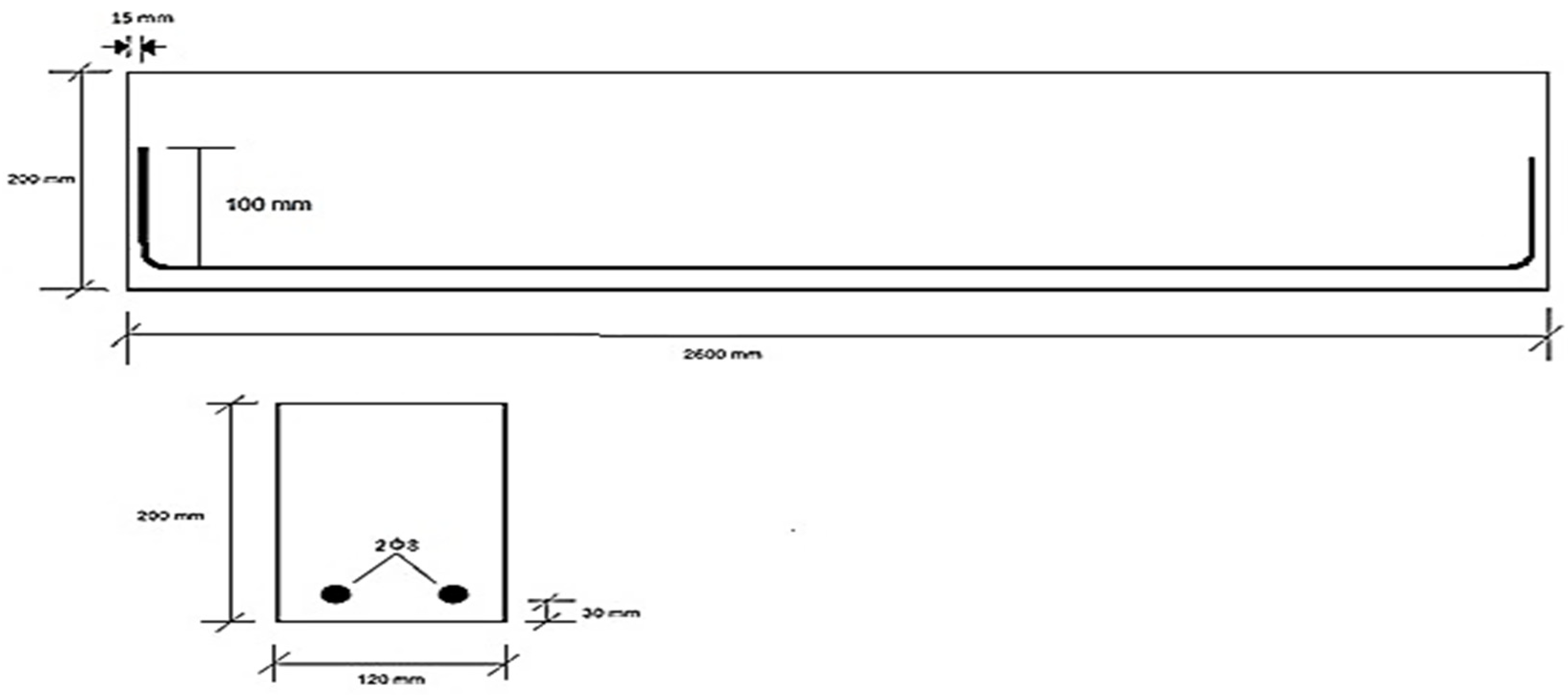
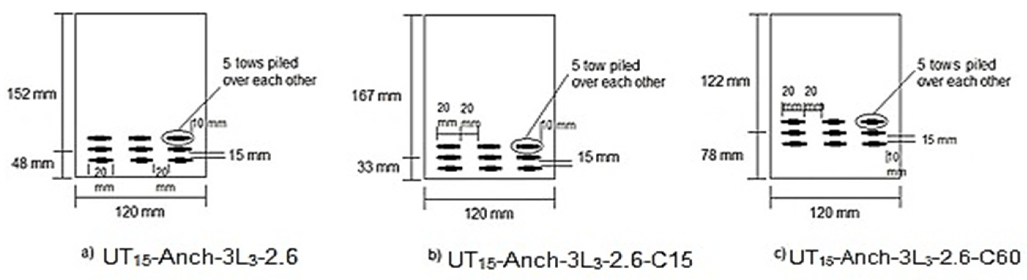
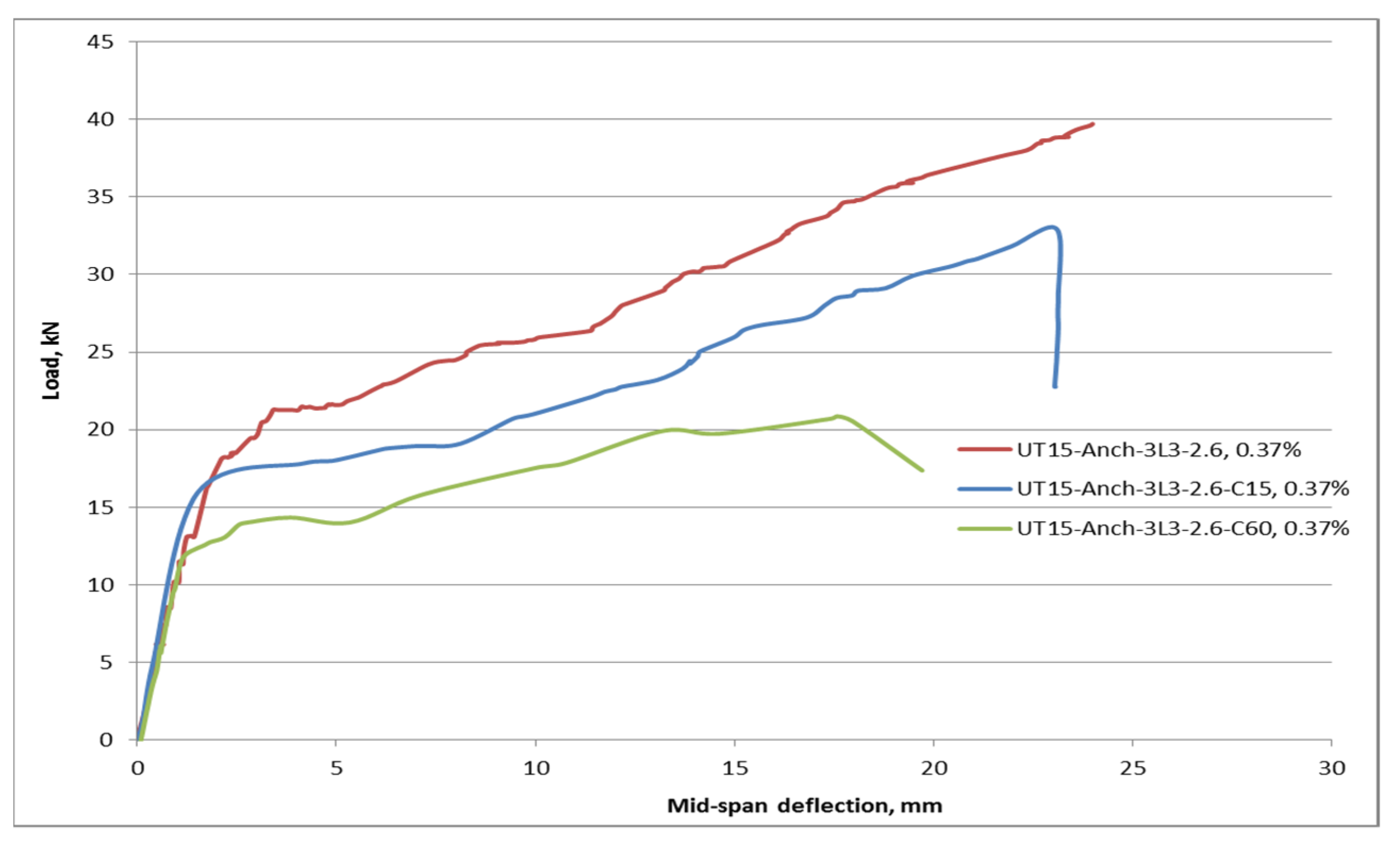
Corrosion resistance can be considered one of the main benefits of textiles in TRC beams, which can be the reason for lower cover thickness. This decrease in thickness may be advantageous in terms of reduced concrete usage and, as a result, lower construction costs. As a result, the influence of cover thickness variation on TRC beam flexural performance was examined.
Table 11 shows the results of the experimental test on TRC beams with various cover thicknesses. C15 and C60 denote cover thicknesses of 15 mm and 60 mm, respectively.
Figure 20 shows the reinforcement details and cover thickness of different TRC beams. UT
15-Anch-3L
3-2.6 has a 30 mm cover thickness. As can be observed from the table, raising or reducing the cover thickness has a negative impact on load-bearing capacity.
The ultimate flexural load of the UT
15-Anch-3L
3-2.6-C15 beam with 15 mm cover was 17% lower than that of the UT
15-Anch-3L
3-2.6 beam with 30 mm cover thickness was with the same layout geometries. The load capacity should theoretically increase because the effective depth has been increased to 167 mm rather than 152 mm. It could be due to a lack of appropriate bonding as a result of the thin cover. Due to the bond loss, the textiles cannot reach their ultimate tensile stresses [
30]. The load capacity of the UT
15-Anch-3L
3-2.6-C60 with 60 mm cover was reduced by about 45% compared to that of the beam with 30 mm cover thickness. Because there is no bond issue concerning cover thickness, this finding could be explained by reducing the adequate depth reduces the reinforced beam’s load capacity.
The thickness of the concrete cover is also a factor in the initial crack, as seen in
Figure 21. It was observed that the beams with higher cover thicknesses obtained the lowest first-crack loads. This outcome is likely related to the fact that a loaded beam’s tension zone is unreinforced 60 mm from the bottom. This signifies that as the concrete reaches the cracking moment, the cracking process continues till the cracks reach the textile reinforcements, where at this point, the loads are transferred to the reinforcements [
31]. The early fracture load of a 15 mm thin cover is lower than 30 mm but greater than 60 mm. The weaker bond owing to the smaller cover thickness could be explained by the observed drop in the first breaking load.
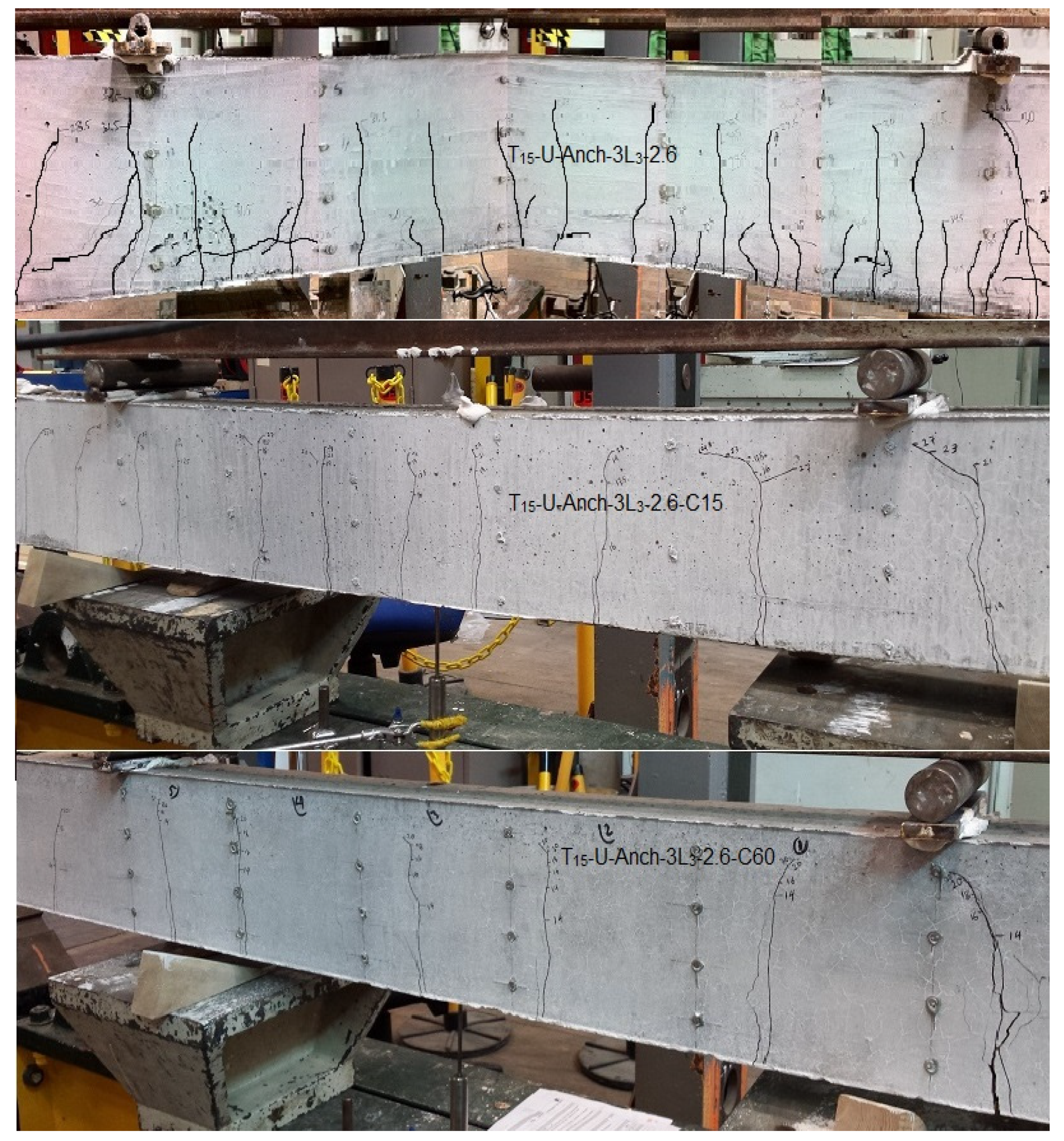
The number and width of cracks formed are also affected by the thickness of the cover. The crack patterns of UT
15-Anch-3L
3-2.6-C60 and UT15-Anch-3L3-2.6-C15 TRC beams are shown in
Figure 22. It can be observed that the beams with 15 mm cover have about nine major cracks, while in the beams with a cover of 60 mm, the number of cracks was 6, which was comparatively lower than 13 for the beams with the cover of 30 mm. The lower quantity of cracks indicates a good bond between the textiles and concrete. However, it was noted that with the rise in the cover thickness, the width of cracks increased. Accordingly, based on the obtained results and the observations made, the TRC beams with 30 mm were performed better, and therefore 30 mm concrete cover thickness could be the optimum value for TRC beams. This optimum cover in TRC beams provides the appropriate and necessary bond to permit textile reinforcements to maximise the tensile stress utilisation, resulting in higher resistance against applied loads and sufficient flexural strength [
32].
Concrete’s tensile strength is roughly 10% of its compressive strength. The concrete’s low tensile strength usually causes cracking [
33]. Crack spacing in reinforced concrete spanning elements is influenced by several factors: member thickness or depth, reinforcement ratio, cover thickness, and bond strength [
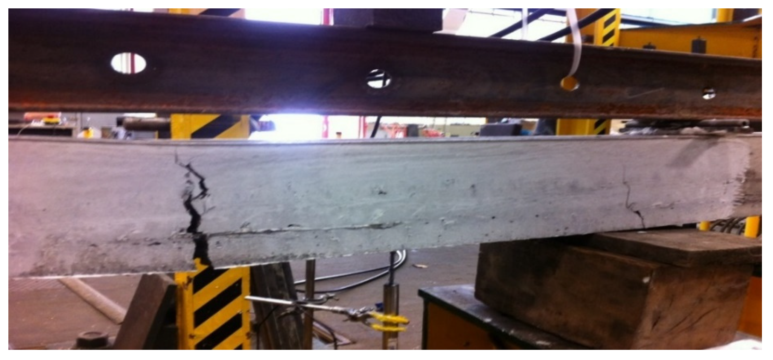
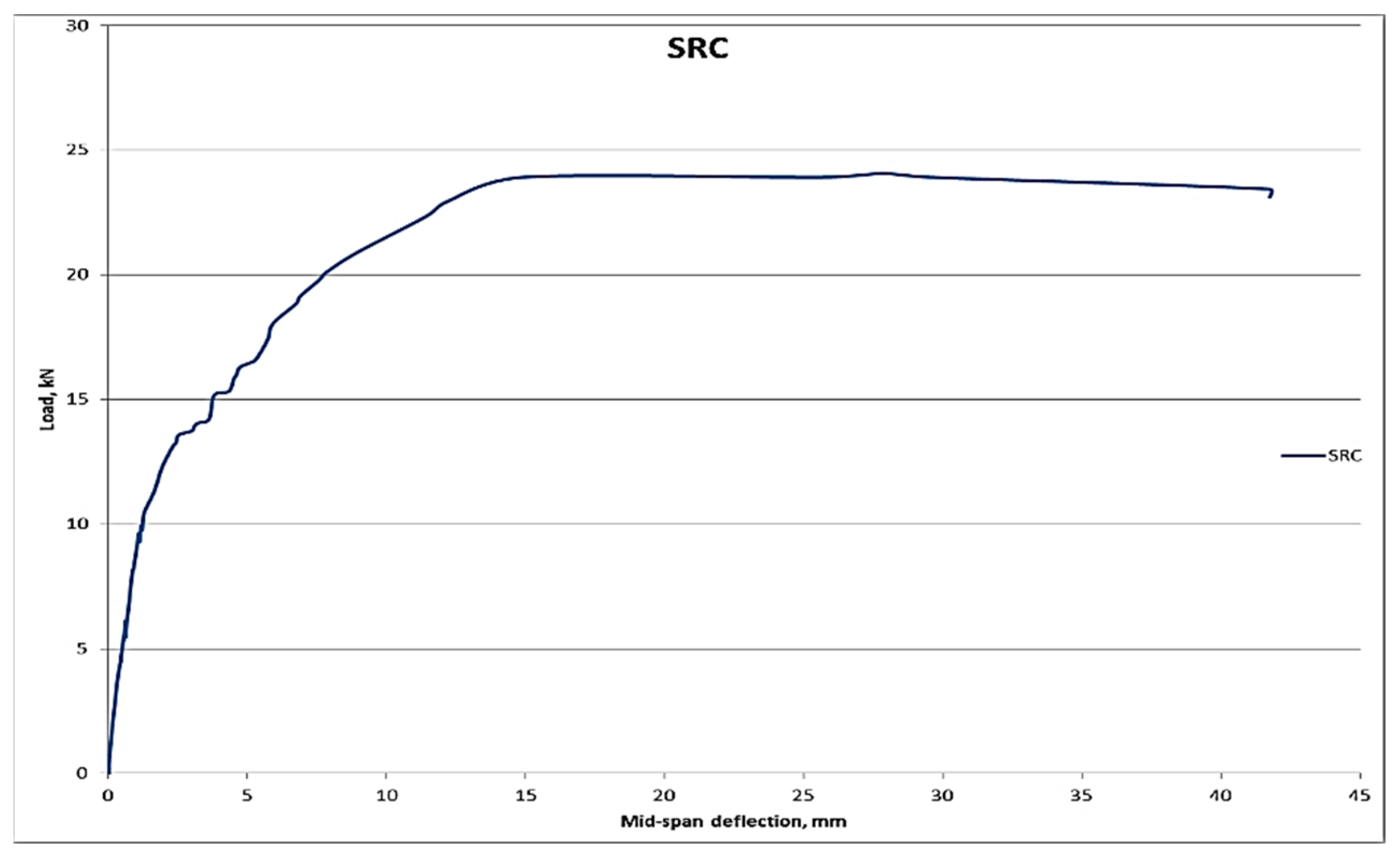
34]. The distance between cracks in TRC and SRC beams was tested experimentally. The crack pattern created in the steel-reinforced concrete is 10 initial cracks, stabilised at an applied load of 20 kN within the constant moment zone, as shown in
Figure 15 and
Figure 22, with an average crack spacing of 11.3 cm and a range of 6 to 15 cm. At roughly 85% of ultimate load and 20% of ultimate deflection, cracking has totally stabilised. Furthermore, the TRC beam test showed a crack pattern consisting of 13 primary cracks stabilised at a load of 26 kN, with an average crack spacing of 9 cm and a range of 6 cm to 15 cm. At roughly 70% of ultimate load and 30% of ultimate deflection, it is entirely stabilised. Furthermore, the TRC beam is distinguished from the SRC beam in terms of tiny cracks.
In comparison to the steel-reinforced beam, the TRC has a lot of small and horizontal cracks. The horizontal cracks can be explained by the horizontal cover thickness of 10 mm; thus, these cracks appear to be secondary/bond cracks. The additional cracks in the TRC beams are intriguing because they imply that the bond stress between the fibres and the concrete can develop faster than the bond stress between steel and concrete. This level of improvement in the bond was possibly unexpected, given that previous indicators showed that the fibres would have a lower bond/contamination with the concrete. Because of the configuration of the fibres within the beam cross-section in these large beam experiments, the situation may be improved [
35].
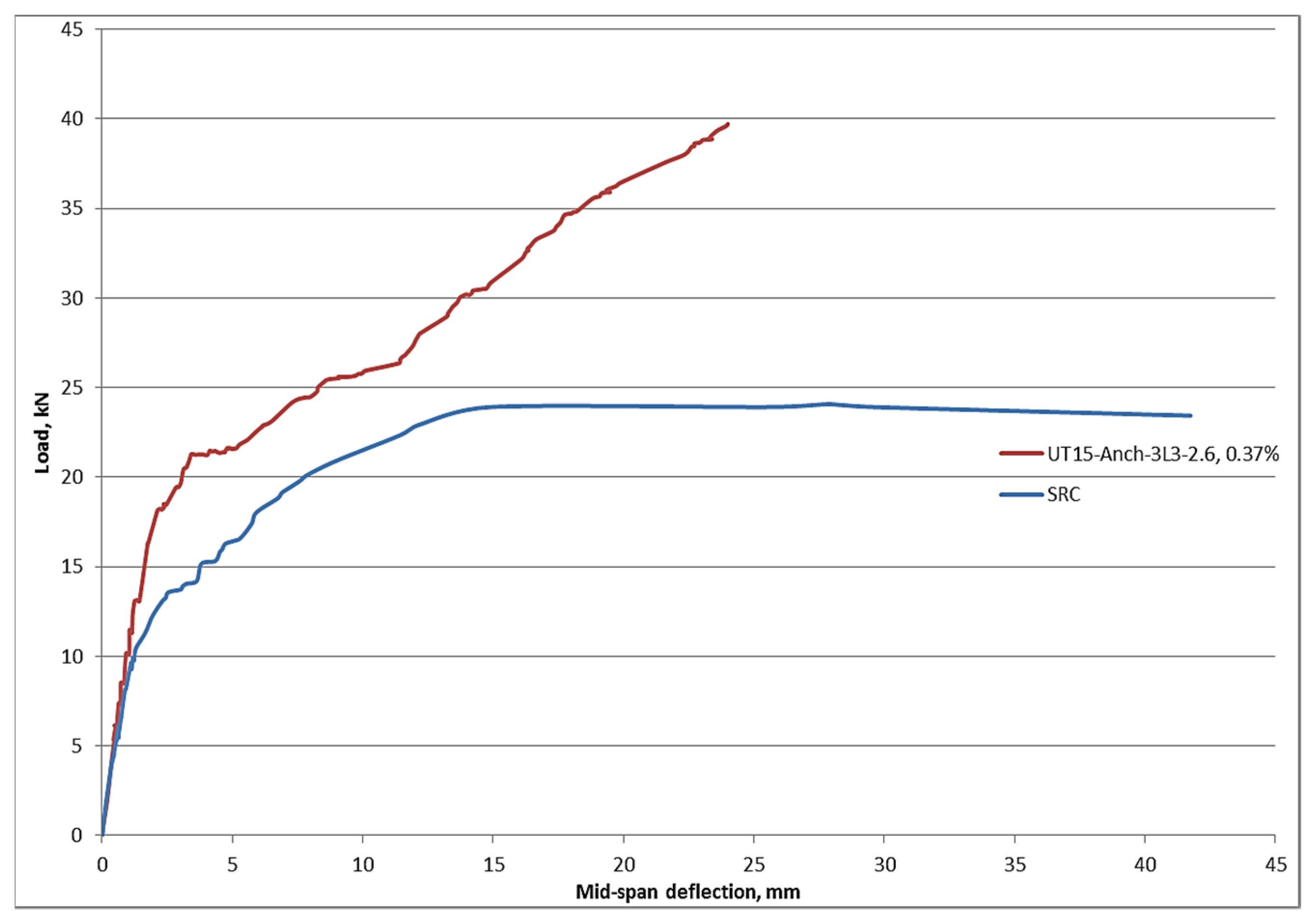
The load-deflection behaviours of large-scale UT
15-Anch-3L
3-2.6 and SRC beams are compared in
Figure 23. Carbon textiles and steel bars were used as uni-axial reinforcement in the beams. The reinforcing area was nearly identical. The ultimate flexural load capacity of the carbon-tow-reinforced concrete beam is significantly greater than that of the steel-reinforced beam, as can be observed. The UT
15-Anch-3L
3-2.6 beam has a 60% higher strength capability than the SRC beam. Furthermore, the TRC beam has a greater rigidity than the SRC beam. The steel-reinforced beam is more plastic after cracking formation, as seen in the figure. The ultimate deflection of the UT
15-Anch-3L
3-2.6 beam is 40% smaller than that of the SRC beam. This is owing to the steel reinforcement’s yielding deformation [
36,
37]. According to the diagram, after reaching yielding strength, the ultimate steel reinforcement strength remains constant until the failure point is reached, regulated by the steel’s ultimate strain. Meanwhile, after all of the primary cracks occurred, the carbon-reinforced beam’s strength continues to increase until it reaches the failure point, which is regulated by the final strain of the textile reinforcement. The TRC beam, on the other hand, has a lower deflection at service loads than the SRC beam [
38]. Although both beams have the same slope at service loads, the TRC beam deflects roughly 50% less than the SRC beam.


