Article

Surface Stabilized Topological Solitons in Nematic Liquid Crystals

1
Department of Electronics and Information Systems, Faculty of Engineering and Architecture, Liquid Crystals and Photonics Group, Ghent University, Technologiepark-Zwijnaarde 126, 9052 Gent, Belgium
2
Faculty of Mathematics and Physics, University of Ljubljana, Jadranska 19, 1000 Ljubljana, Slovenia
*
Author to whom correspondence should be addressed.
Crystals 2020, 10(9), 840; https://doi.org/10.3390/cryst10090840
Submission received: 28 August 2020 / Revised: 15 September 2020 / Accepted: 17 September 2020 / Published: 19 September 2020

Abstract

:
Photo-alignment is a versatile tool to pattern the alignment at the confining substrates in a liquid crystal (LC) cell. Arbitrary alignment patterns can be created by using projection with a spatial light modulator (SLM) for the illumination. We demonstrate that a careful design of the alignment patterns allows the stabilization of topological solitons in nematic liquid crystal (NLC) cells, without the need for chirality or strong confinement. The created LC configurations are stabilized by the anchoring conditions imposed at the substrates. The photo-aligned background at both substrates is uniformly planar aligned, and ring-shaped regions with a 180° azimuthal rotation are patterned with an opposite sense of rotation at the top and bottom substrate. A disclination-free structure containing a closed ring of vertically oriented directors is formed when the patterned rings at the top and bottom substrate overlap. Thanks to the topological stability, a vertical director orientation in the bulk is observed even when the centra of both patterned rings are shifted over relatively large distances. The combination of numerical simulations with experimental measurements allows identification of the 3D director configuration in the bulk. A finite element (FE) Q-tensor simulation model is applied to find the equilibrium director configuration and optical simulations are used to confirm the correspondence with experimental microscopy measurements. The created LC configurations offer opportunities in the field of optical devices, light guiding and switching, particle trapping and studies of topological LC structures.

Graphical Abstract

1. Introduction

The development of reliable photo-alignment methods to define the LC anchoring at confining substrates has led to a rapid evolution in the field of LC photonic devices, soft actuators, micro-particle placement and in the command of active matter [1,2,3,4,5,6,7,8,9]. Different illumination techniques (interference illumination, direct write illumination, projection illumination with a spatial light modulator (SLM), plasmonic patterning, etc.) can be used to create alignment patterns with high-resolution and close to arbitrary variations in the preferred azimuthal anchoring at the substrate [10,11,12,13,14,15,16]. This has been successfully applied to create very efficient transmissive and reflective LC flat-optics devices, that are manipulating the so-called geometric (or Pancharatnam-Berry) phase of light. Micrometer thin optical components (such as microlens arrays, beam shaping elements and polarization gratings) with close to 100% efficiency were demonstrated in this way and high-quality vortex beams and vector beams were generated [6,7,8,9,17,18,19,20]. Photo-aligned LC samples can also be applied to steer the placement of micro-particles, to control active matter (influence bacterial movement) and to make stimuli-responsive soft actuators [1,2,3,4,5].
Photo-alignment is a non-contact method that allows high-throughput and high-resolution patterning of straight and curved substrates without the introduction of dust or electrostatic charges. In a standard LC cell, the top and bottom substrate can easily be patterned with different (periodic or non-periodic) alignment patterns. This ability was exploited in recent years to create an artificial web of disclination lines (in non-equilibrium conditions) [21], and to stabilize 2D diffractive structures with intricate bulk director configurations demonstrating symmetry breaking and regions with pronounced non-planar director orientation in the bulk [22,23,24,25]. In general, patterned planar photo-alignment offers valuable possibilities to study the formation of (twist) disclination lines, their interaction and their annihilation when the alignment patterns are well designed [21,22,23,24,25,26,27,28,29,30]. When a different azimuthal angle is imposed at corresponding locations at the top and bottom substrate, a position dependent twist in the bulk can occur. However, for some combinations of alignment patterns at the substrates, the topology at the interfaces requires either the creation of disclinations in the bulk or regions with vertical director orientation [15,23,24,25,26,27,28,29,30]. We recently demonstrated for different alignment configurations that surface induced twist conflicts are often elegantly resolved, without the need for singular disclination lines, by introducing a region with vertical director orientation in the bulk of the device [15,23,24,25]. Honma et al. described the same phenomenon as the formation of so-called “thick disclinations” (upon combination of two thin disclinations, without the presence of singularities in the final configuration) and Ouchi et al. discussed this phenomenon as the stabilization of nonsingular wall loops [26,28].
We here use these insights to stabilize a new type of topological solitons in NLC cells in which both substrates are patterned. This in contrast to previous works where one patterned substrate was combined with a uniformly aligned substrate [15,26,27]. Solitons, or so-called particle-like topological states, are usually studied in chiral LC samples with strong confinement [31,32,33,34,35,36,37], but photo-alignment techniques allow studying soliton structures in less confined configurations [38] and non-chiral cells [15,26,27]. We investigate new soliton-like NLC structures induced by well-designed ring-shaped alignment patterns at the confining substrates. We fully exploit the flexibility of an SLM-based illumination setup to define custom-designed alignment patterns at the substrates [14,15]. The photo-aligned background at both substrates is uniformly planar aligned along the x-direction, but closed ring-shaped regions with a 180° rotation of the azimuthal angle (between rout and rin = 0.4 * rout) are patterned at the top and bottom substrate (Figure 1). In the ring-shaped patterns at both substrates, the azimuthal angle is rotating with an opposite sense of rotation (Figure 1a). Different dimensions of the alignment patterns were experimentally tested, with rout varying between 30 µm and 50 µm, and gave rise to roughly similar results in a 5.5 µm thick cell. It is demonstrated that the topological structures formed in the bulk, with a ring-shaped region with vertical director orientation, are inherently stable upon voltage cycling and are not easily destroyed by deviations in the anchoring configuration.
To gain detailed insight in the LC behavior in the bulk of the device, experimental measurements are combined with numerical simulations. The equilibrium director configuration is found by minimizing the Landau-De-Gennes (LDG) free energy with the help of finite element (FE) Q-tensor simulations [39,40,41,42,43,44]. Based on the director configuration, optical micrographs are simulated with a beam propagation method (BPM) [45]. Comparison between the simulated micrographs and optical microscopy measurements validates the accuracy of the simulation results.
The rest of the paper is structured as follows. In Section 2 the cell fabrication process and photo-alignment setup are discussed, as well as the simulation methods that are used to identify the director configuration and the resulting optical properties. In Section 3 polarization optical microscopy (POM) images are shown and results from the FE Q-tensor simulations for the director configuration are presented. The corresponding optical micrograph simulations are compared to experimental measurements and the results are discussed and interpreted in perspective of previous studies in Section 4. Last, concluding remarks are formulated and possible extensions of the work are discussed.

2. Materials and Methods

The LC cells are prepared by assembly of two photo-patterned substrates, separated by spacers with a 5.5 µm diameter. After cleaning the glass substrates (1.1 mm float glass coated with an indium tin oxide coating, Delta Technologies) and treating the substrates with UV-ozone, the photo-alignment material (0.2 wt.% Brilliant Yellow (BY) dissolved in 99.8 wt.% dimethylformamide (DMF), both purchased from Sigma-Aldrich) is spincoated on top of the substrates (3000 rpm, 30 s) and the solvent is evaporated by baking on the hot plate (90 °C, 5 min). Based on previous reports, the 0.2 wt.% BY solution is expected to give rise to an alignment layer with a thickness of only a few nanometer [46]. The thermal-stability or photo-stability of the alignment layer was not studied in detail here. Previous publications suggest a good thermal stability of BY-based photo-alignment layers [47], and different solutions were proposed to improve the photo-stability [46,48]. The spacers are dissolved in UV-curable glue (NOA 68) and only the glue pattern is exposed to UV light for curing, in order not to destroy the pre-written alignment pattern on the substrates. The samples are heated to 75 °C before being filled with nematic LC (E7).
Before cell assembly the substrates are separately illuminated with an SLM based projection setup to impose the preferred alignment pattern (Figure 1c). The patterned SLM retardation is translated into a spatial pattern of polarization directions [14,15]. Blue laser light (Cobolt Twist, 200 mW, λ = 457 nm) is projected onto the substrate as depicted in Figure 1c. The emitted vertically polarized light from the laser is converted into circularly polarized light by quarter-wave plate Q1 and expanded by lenses L1 and L2 to illuminate the full surface of the SLM (Holoeye, Pluto-2, pixel pitch 8 µm, 1920 × 1080 pixels). In every pixel of the SLM the phase of the horizontal polarization component is modulated, with a magnitude that depends on the voltage applied to the corresponding pixel. The phase modulation is then converted into a rotation of the linear polarization by quarter-wave plate Q2. The projection of the SLM on the sample can be scaled up or down by changing the position of the projection lens L3. For the reported experiments, the magnification factor is approximately 0.085, resulting in a projected pixel dimension of 0.68 µm. Upon illumination, the BY molecules in the photo-alignment layer orient perpendicularly to the local orientation of the linear polarization.
An elementary building block of the alignment pattern on the substrates is shown in Figure 1a. Both at the bottom and top substrate, an alignment parallel to the x-direction is imposed in the background (surrounding the ring pattern) and in the central area of the ring. A 180° rotation of the azimuthal anchoring angle φ is introduced in ring-shaped regions (between inner radius rin and outer radius rout) at the top and bottom substrate, with the opposite sense of rotation at both substrates:
φ = 0     for r < rin,
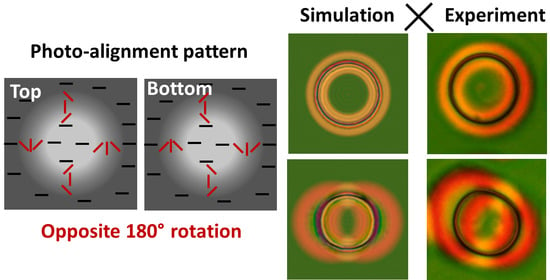
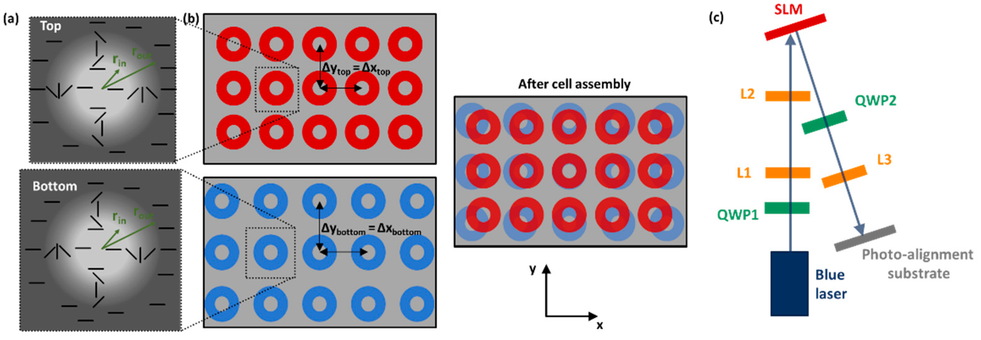
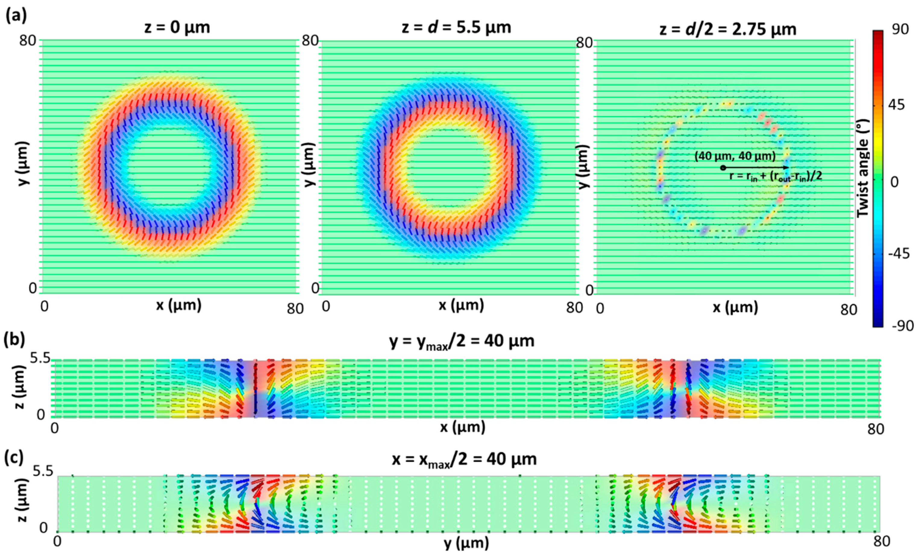
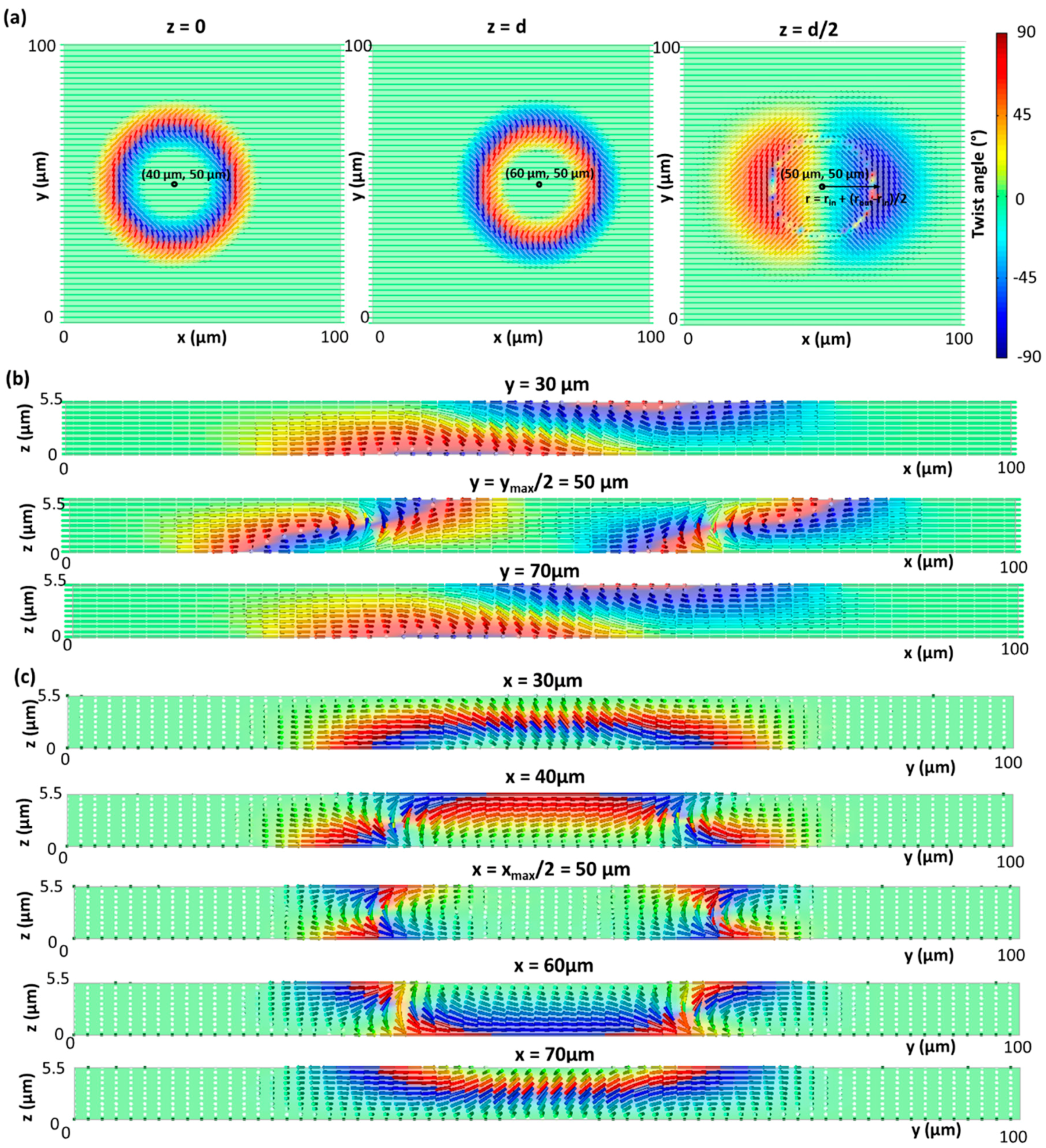
φ = +/− π (r − rin)/(rout − rin)  for rin < r < rout,
φ = +/− π    for r > rout
With the plus and minus sign in Equation 1 being applicable for the top and bottom substrate respectively (Figure 1a). Different dimensions of the ring-shaped regions were tested, with rout varying between 30 µm and 50 µm, and rin always equal to 0.4 * rout. The total illumination pattern, projected by the SLM on the sample, consist of multiple patterned rings with a fixed spacing between the centra of the rings in the x- and y-direction (Δxtop = Δytop and Δxbottom = Δybottom, Figure 1b). Since precision alignment of the top and bottom substrate is difficult to achieve in our custom-build setup, a slightly different spacing between the patterned rings at the top and bottom substrate is used: the dimensions of the patterned rings (rout, rin) at both substrates are identical, but the centra are separated over Δxtop = Δytop = 100 µm in the x- and y-direction at the top substrate and Δxbottom = Δybottom = 107 µm at the bottom substrate. In this way, good overlap between the rings at the top and bottom substrate is obtained at least at some positions in the patterned cell (Figure 1b). At deviating positions in the same cell, also the effect of shifted alignment patterns at the top and bottom substrate can be studied.
To simulate the 3D LC director configuration in the bulk of the cell, FE Q-tensor simulations are used. The custom written simulation method, developed at University College London [41,42,43,44], is based on a minimization of the Landau-de Gennes (LDG) free energy functional. A continuum model is used where the LC is described by a symmetric second order tensor (Q-tensor) [39,40]. In short, the total free energy in the LDG formalism contains contributions from the elastic distortion energy, the thermotropic (or Landau) energy, the surface energy and external (electric) field induced energy when external fields are applied. The different energy terms are expressed in terms of the order tensor Q. The description of the LC with a symmetric tensor instead of a vector allows modeling disclinations and local variations in the order parameter. Variations of the order parameter in the vicinity of a defect core give rise to a contribution to the thermotropic energy term. A more detailed discussion of the simulation method can be found in previous publications [15,41,42,43,44].
The simulated ring-shaped alignment patterns have a fixed dimension rout = 30 µm and rin = 0.4 * rout. Two alignment configurations are simulated: one with the ring-patterns at the top and bottom substrate centered at the same position (configuration 1) and one with a 20 µm shift in the x-direction between both centra (configuration 2). The dimensions of the simulated unit cell are 80 µm × 80 µm for configuration 1 and 100 µm × 100 µm for configuration 2. Periodic boundary conditions are applied in the x- and y- directions. The anchoring at the top and bottom substrate is assumed to be strong, with a 0° pretilt angle and an azimuthal angle that is fixed to the values defined in Equation (1). The elastic constants of E7 are taken into account in the simulation model (K11 = 11.1 pN, K22 = 6.5 pN, K33 = 17.1 pN) and the thermotropic parameters are fixed to A = −2 * 0.87 * 102 N/m2, B = −2.12 * 103 N/m2, C = 1.74 * 103 N/m2, giving rise to an equilibrium order parameter 0.54 at a reduced temperature of −2 °C (as discussed in [15]).
Based on the results for the director configuration, optical micrographs are simulated with the help of a generalized beam propagation method (BPM) for propagation of the optical fields. The director configuration is simulated on a tetrahedral volume mesh and the results are interpolated on a regular grid for BPM calculations. The optical simulations rely on the open-source software Nemaktis (https://github.com/warthan07/Nemaktis) which implements part of the generalized BPM framework recently introduced by Poy et al. for general birefringent media [45]. In short, Maxwell equations for birefringent media are recast in a simpler Schrödinger-like propagation equation for the transverse field. This includes a dominant contribution to the phase evolution (similar to the Jones Method), a diffraction operator including the anisotropy of the permittivity tensor and a walk-off operator taking into account tilt between the Poynting vector and the wavevector. The numerical aperture of the focusing optics in the microscope is taken into account by using the well-known formula of Fourier optics to obtain the final image [49], and the spectrum of the CIE illuminant A is used to reproduce the color images. The dispersion of the ordinary and extraordinary refractive index of E7 are taken into account using the Cauchy formulas:
no = 1.49669 + 0.00785 µm22 + 0.00026 µm44, 
ne = 1.67906 + 0.01546 µm22 + 0.001663 µm44

3. Results

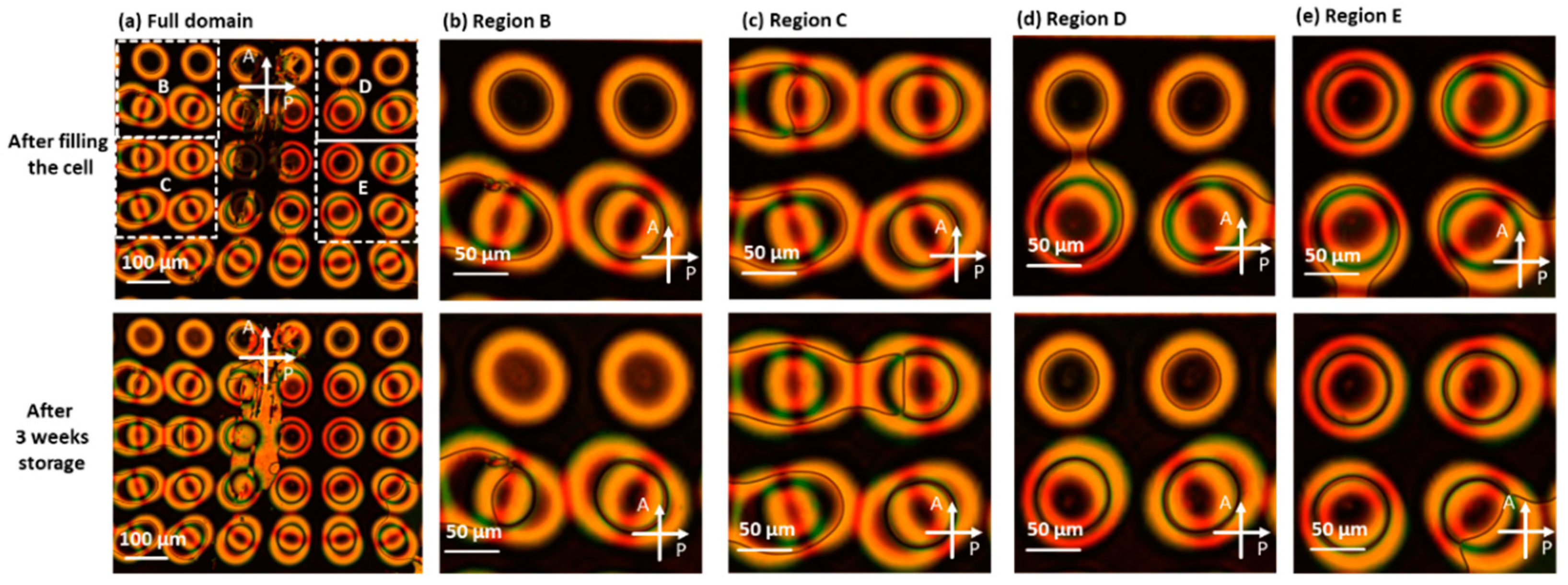
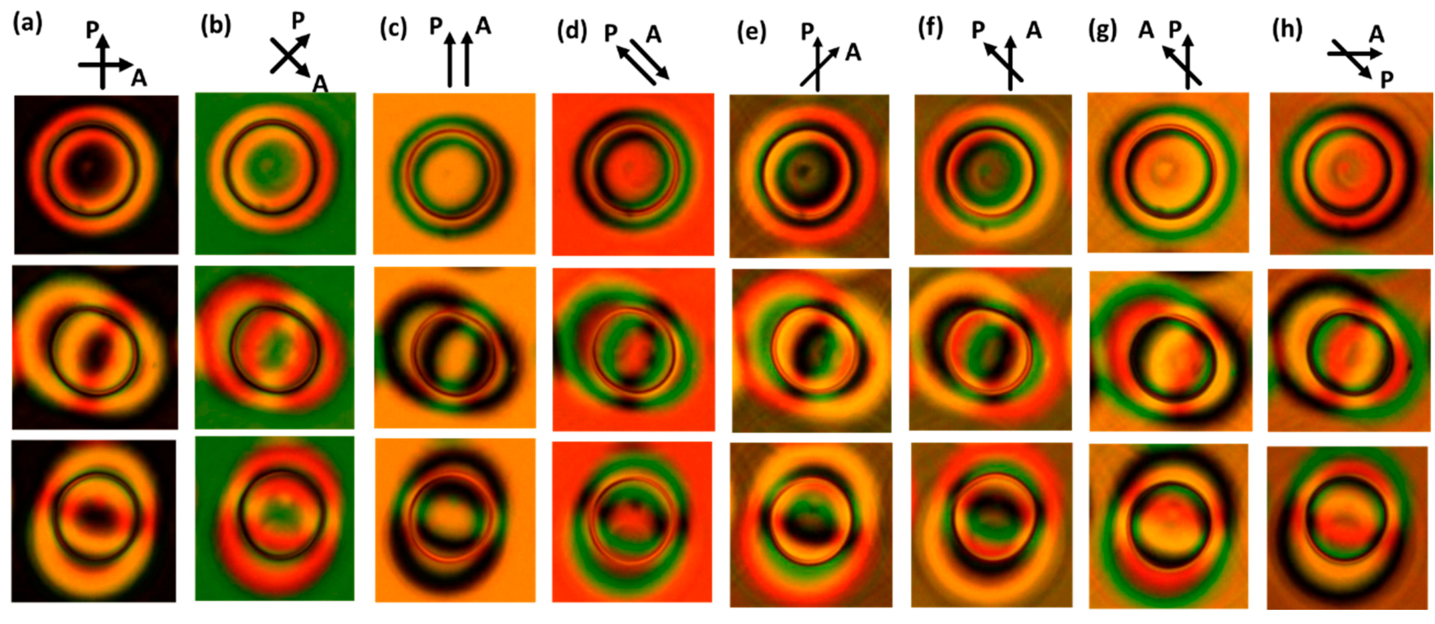
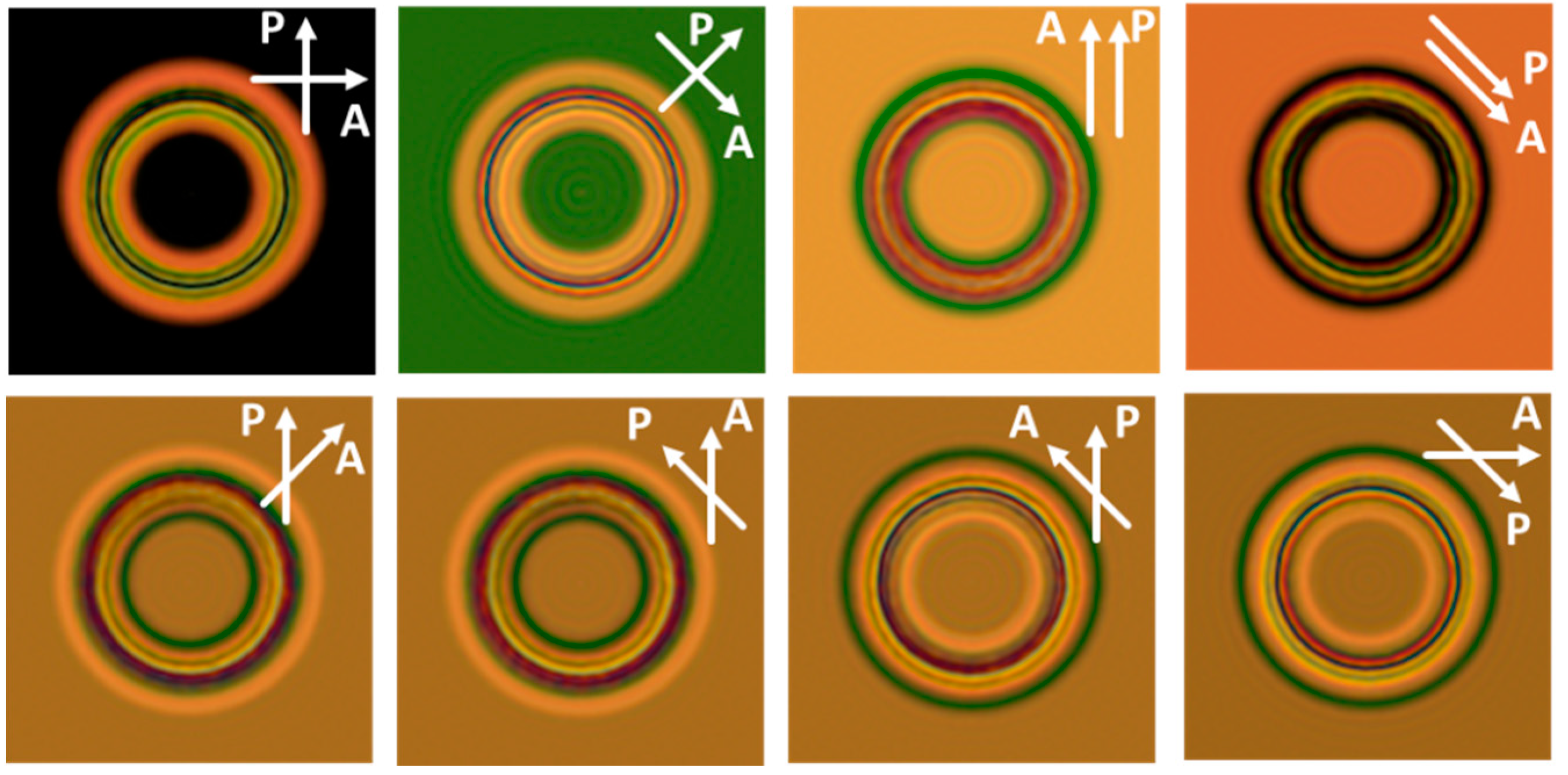
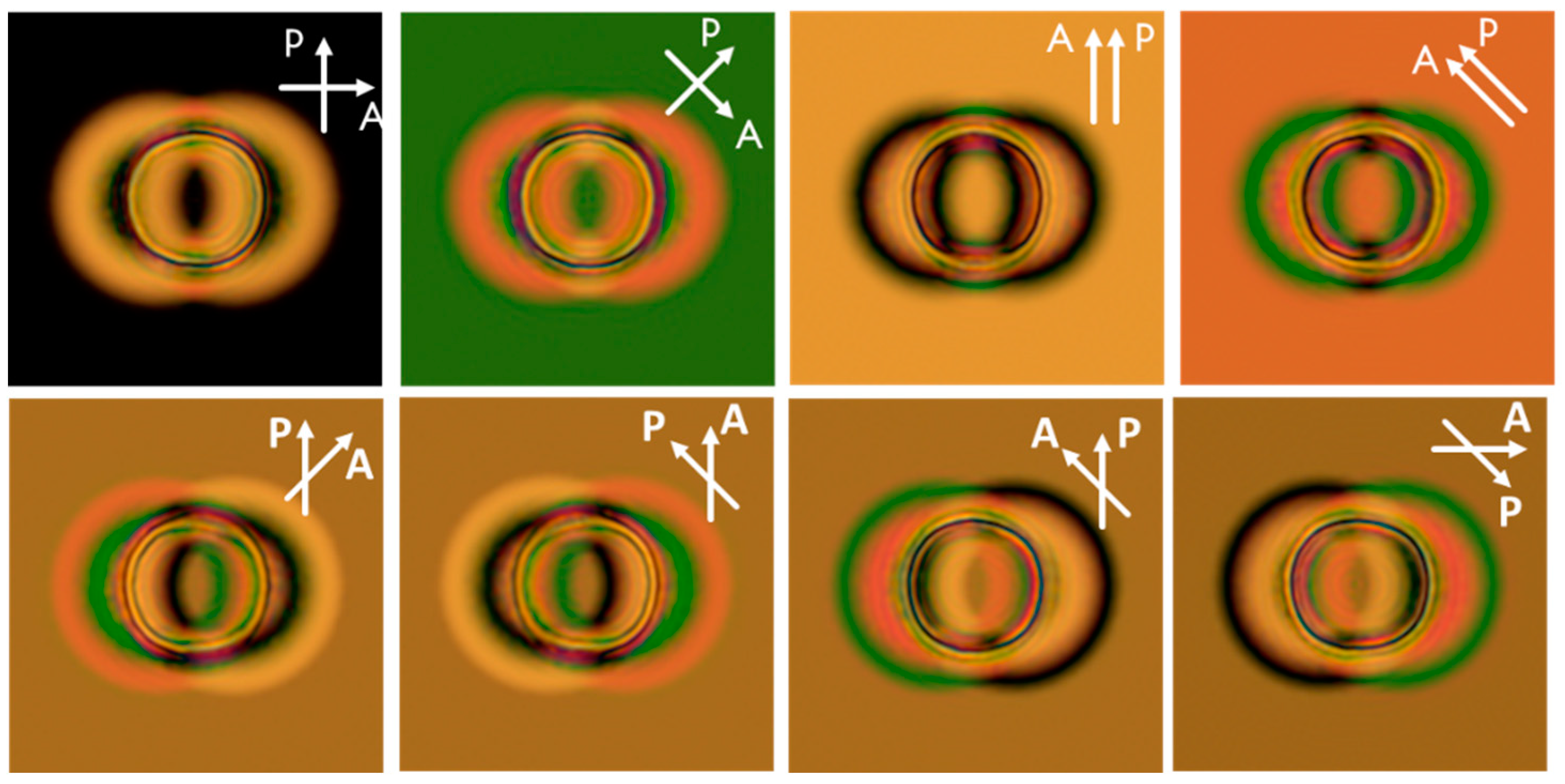
3.1. Experimental Results

After filling the cell with LC, the cell is cooled down to room temperature before measuring the optical micrographs with a polarizing optical microscope. A voltage of 10 Vpp (at 1 kHz) is applied during the cooling process and removed when the cell is at room temperature. Similar results are obtained when the cell is cooled down without applied voltage. To get better insight in the LC director configuration, the cell is observed for different orientations of the polarizers and also in the absence of polarizers.
Microscope images for the cell between crossed polarizers are shown in Figure 2 and Figure 3 for two different orientation of the polarizers. The first row shows images obtained shortly after preparing the cell, the images in the second row were measured after three weeks (without reapplying a voltage or reheating the sample). The images are taken in an area of the cell with dimensions of the patterned rings rout = 50 µm (and rin = 0.4 * rout). A larger area is shown in Figure 2a and Figure 3a to demonstrate the effect of our alignment method, with a slightly different spacing between the rings at the top and bottom substrate. In the ring structures that are visible in the top row of Figure 2a and Figure 3a, the patterned ring-shaped alignment is only present at one of both substrates, while the other substrate contains uniform planar alignment along the x-direction. In the rest of the area shown in Figure 2a and Figure 3a, both the top and bottom substrate are patterned and there is at least partial overlap between the rings at both substrates. Due to the scratch that is present in the cell, the number of ring structures with (close to) perfect overlap between the centra of the patterned rings is limited in this image. However, this imperfection makes it easy to recognize this region and evaluate the stability over time and upon voltage cycling. To demonstrate the long term stability, the same area of the cell was imaged three months after preparing the cell and the images are shown in Appendix A. Results are reported after three months storage (Figure A1a) and after applying a voltage of 10 Vpp (1 kHz) to the cell (Figure A1b). The results after three months exactly correspond to the results reported in the second row of Figure 2 and Figure 3 and applying a voltage has only a minor effect on the results. Upon voltage application, some movement of disclinations (e.g., in the bottom right corner of the figures) is observed in regions with neighboring alignment rings that are not well separated. Voltage application (and subsequent removal) has no effect when there is perfect overlap between the alignment rings at the top and bottom substrate.
Figure 2 and Figure 3 contain a lot of information that will be analyzed step by step. Let us first focus on the simplest phenomenon that is observed in regions where substrate patterning is only present at one of both substrates. This is the case for the ring structures in the top row in Figure 2a and Figure 3a, of which an enlarged view is shown in Figure 2b,d and Figure 3b,d. A patterned ring structure with a 180° rotation of the azimuth at one substrate is here combined with uniform planar alignment (along x) at the opposite substrate. This initially gives rise to the formation of a closed-loop disclination with ½ strength. Interestingly, this disclination loop can shrink and disappear by introduction a 180° twist in the unpatterned middle region of the ring (r < rin). This effect is clearly observed in the top two ring-structures shown in Figure 2b and Figure 3b where the disclination loop disappeared after three weeks and the middle region obtained another color in transmission thanks to the 180° twist. This effect was not observed in the top two ring-structures shown in Figure 2d and Figure 3d, which seems to indicate that both LC configurations have similar energy and their appearance depends on the history of the sample and local details (alignment strength, cell thickness, etc.). We previously demonstrated a similar effect, with shrinkage of a disclination loop and introduction of a 180° in the middle, in a cell with a uniformly aligned top substrate and a bottom substrate with ring-shaped alignment patterns with 360° (instead of 180°) rotation in the azimuth [15]. In this case, shrinkage of one of the two disclination loops also gave rise to a 180° twist in the middle of the rings (called “structure B” in [15]). Since the cell thickness in the current and the previous experiment are identical, the color effect can be easily compared and the simulations results are not repeated in this manuscript: in both cases a change from dark green to light green transmission is observed in the middle of the rings for a 45° orientation of the crossed polarizers.
Let us now focus on more complex phenomena that are observed in regions of the cell where the substrate patterning is present at both substrates (all structures except the top row in Figure 2a and Figure 3a. Intuitively one could expect that two disclination rings with strength ½ would be formed in this case, one connected with the top substrate and one with the bottom substrate. This configuration is however never observed, but in many cases a disclination-free director configuration is formed. Initially, immediately after filling the cell (first row in Figure 2 and Figure 3), single disclination lines are sometimes observed, especially thanks to interaction with neighboring alignment structures that are not well separated. However, after voltage cycling or letting the sample equilibrate (second row in Figure 2 and Figure 3), more disclination-free structures are observed. This is clearly visible in Figure 2d,e and Figure 3d,e were in both cases two ring structures evolved towards a disclination-free structure. The middle region of these disclination-free ring structures has the same optical transmission as the unpatterned background (surrounding the ring patterns) with uniform alignment in the x-direction. This hints that uniform planar alignment is present in the middle region of these rings, with a bulk director that remains planar and parallel to the surface alignment at both substrates. In the rest of this paper we will focus on these disclination-free ring structures that are induced in regions with a decent overlap between the alignment patterns at the top and bottom substrate. As expected, disclination lines are regularly observed in regions with a very large shift between the alignment patterns at both substrates but this will not be discussed in more detail.
The microscopy images in Figure 4 clearly demonstrate that disclination-free director configurations are also repeatedly observed for moderately large shifts between the rings-shaped alignment patterns at the top and bottom substrate. These images focus on an area in the sample with a non-negligible shift of the alignment patterns, where in the bottom-right corner, some singular disclinations are observed. An image without polarizers is also added in Figure 4, to make the presence or absence of singular disclinations (visible as thin black lines) more eye-catching.
A more detailed microscopy analysis of three individual disclination-free ring structures is shown in Figure 5 for different orientations of the polarizers. One structure with close-to perfect overlap between the alignment patterns is chosen, as well as two structures with a shift between the alignment patterns. The microscopy images with a 45° rotation between the analyzer and polarizer Figure 5e–h are especially interesting to study the colors in the side lobes of the structures with shifted alignment patterns.
Finally, some microscopy images are shown in Figure 6 for regions in the cell with smaller dimensions of the patterned ring structures at the substrates (rout < 50 µm). In Figure 5a the ring structures at the top and bottom substrate have rout = 40 µm (rin = 0.4 * rout), while the outer dimension of the patterned rings is rout = 30 µm (rin = 0.4 * rout) in Figure 5b. Very similar effects are observed, with the formation of 8 disclination-free ring structures in Figure 5a and four completely defect-free ring structure in Figure 5b. The presence of some disclination lines and defects in Figure 5 is related to the presence of a scratch in the cell at this position.

3.2. Simulation Results

To fully understand the experimentally observed phenomena, numerical simulations are indispensable. We focus on the simulation of the disclination-free structures that are observed in regions with a perfect overlap (configuration 1) and regions with a substantial shift (configuration 2) between the alignment patterns at the top and bottom substrate. The shift between the centra of the patterned rings in configuration 2 is 20 µm (= rout* 2/3) along the x-direction. For configuration 1, simulation results for the director configuration are summarized in Figure 7 and corresponding results for the simulated optical micrographs are shown in Figure 8. The same results for configuration 2 are summarized in Figure 9 and Figure 10 respectively. Strong deviations from the planar substrate alignment are observed on top of the rings with patterned azimuthal anchoring. To resolve the twist conflict that is introduced by the substrate alignment, the director in the bulk tilts out of the substrate plane and becomes vertical in a ring-shaped region near the middle of the cell (z = d/2). The ring-shaped region with vertical director orientation is situated at a distance of approximately r ≈ rin + (rout − rin)/2 from the center in configuration 1 and from the midpoint between both centra in configuration 2. The introduction of an out-of-plane tilt in the bulk is an elegant solution to avoid the need for twist disclinations.
Even though the centra of the patterned rings at the top and bottom substrate are substantially shifted in configuration 2, a defect-free configuration can still be formed. Comparison between Figure 7 (configuration 1) and Figure 9 (configuration 2) makes clear that the general mechanism between the formation of configuration 1 and 2 is the same: an out-of-plane tilt of the director (with respect to the substrate planes) is introduced to deal with the opposite azimuthal rotation direction in the ring-shaped patterns at the top and bottom substrate. Due to the lateral shift in the x-direction between the alignment patterns in configuration 2, extra twist deformations appear around the ring-shaped region with vertical director orientation in the mid-plane. The further away from the center (x, y) = (50 µm, 50 µm), the more the deformation of the director resembles a pure twist (with minimal out-of-plane tilt). In POM images, these twist-deformations give rise to strongly asymmetric colors in the side-lobes of the ring for a 45° rotation between the analyzer and the polarizer (Figure 10).
Finally, an optical micrograph simulation without polarizers is shown in Figure 11 for configuration 1 and 2. The BPM tool includes the possibility of simulating the effect of varying focus in the microscope and results for three different focusing positions are shown: in-focus (focus 0) and 10 µm out-of-focus in the two directions (focus −10 µm and +10 µm). The images clearly demonstrate that the contrast is not trivial even for these defect-free structures, showing that diffraction is not negligible near the core of the ring. Adjusting the focus has a strong effect on the images and an inversion of contrast can be observed when moving through the focus. This explains why the experimental microscopy images without polarizers in Figure 4 and Figure 6 have a slightly different appearance.

4. Discussion

The presented results clearly demonstrate that interesting 3D LC director configurations can be stabilized by combining ring-shaped photo-alignment patterns with an opposite 180° rotation at the top and bottom substrate. A stable and defect-free soliton structure is formed in the NLC cell when the alignment rings at both substrates at least partially overlap. A local disturbance in a director field that is homogeneous in the far-field can be considered as a soliton. These particle-like topological structures have been studied extensively in LCs since they are an ideal material system to obtain controlled, sometimes reconfigurable, topological patterning of condensed matter [15,26,27,31,32,33,34,35,36,37,38]. Different from previous work, we use achiral LC in combination with two patterned planar alignment surfaces to stabilize soliton-like structures. Substrate patterning allows the precise localization of the structures and adjustments of the alignment patterns can be used to tweak the bulk properties. This flexibility allows controlling the resulting optical properties of the device for electro-optic applications, but also the interaction with micro-particles when colloidal suspensions are infiltrated or the response to external stimuli when a LC elastomer film is produced. A specific application that attracts our attention, is the manipulation of light by the solitonic structures. As recently pointed out by Hess et al. [37], topological solitons introduce spatially localized patterns of effective refractive index that can be used to steer laser beams, act as lenses or other optical elements. Different refractive indices are seen by ordinary and extraordinary waves and the interaction between solitons and laser light can be adjusted by applying low-voltage fields or other external stimuli. Since the director field of an isolated soliton covers the order parameter space once, a large effective refractive index contrast is seen by the light beam, leading to strong interaction. The absence of in-plane rotational symmetry in our solitonic structures might lead to a very rich behavior, including deflection of light but possibly also polarization conversion. This could be an interesting topic of future research.
Numerical simulations for the director configuration and the optical micrographs were used to get insight in the experimentally obtained LC structures. Comparison between the simulated micrographs and optical microscopy measurements allows verification of the simulation results. Excellent agreement can be seen between both (Figure 5 and respectively Figure 8 and Figure 10), confirming that the complex 3D director configuration in the bulk is successfully unraveled. The results reveal that our alignment configuration, in which the director near the substrates remains planar, generates a defect-free bulk director configuration that contains a closed ring in which the director is perpendicular to the substrate. To resolve the twist conflict that is introduced by the substrate alignment, the director in the bulk tilts out of the substrate plane and becomes vertical in a ring shaped region in the middle of the cell (z = d/2). This out-of-plane reorientation in the bulk avoids the need for twist disclinations.
Remarkably, the solitonic structures observed in our system are topologically protected (i.e., they cannot be continuously deformed into the uniform state), and therefore can be addressed as topological solitons. Indeed, we observed from the numerical simulations that the order parameter space RP2 of the nematic phase is covered exactly once by the director field of an isolated soliton. To convince the reader of this rather mathematical statement, we display in Figure 12 a few preimages (1D line-like subset of the LC bulk with a fixed orientation of the director field) associated with configuration 2. Each orientation of the director (taking into account the equivalence n ↔ −n with n the director) is associated with a single color (as determined by its hue and saturation) and a single preimage loop. Our choice of color map is singular along the equatorial line of the S2 spheres, but this does not pose any problem here since the director is rigorously horizontal only on the confining plates and in the far field, not in the bulk of the soliton. Interestingly, the preimage loops clearly shows the shift of the surface patterns in Figure 12a and the central homeotropic region in Figure 12c, thus confirming from a topological point of view why the structure can avoid singularities by creating a loop domain with vertical orientation of the director.
Compared to our previous results, in a cell with uniform alignment at one substrate and a ring-shaped alignment pattern with 360° rotation at the opposite substrate [15], the current alignment configuration allows a much stronger stabilization of the closed ring structure with vertical alignment. When the patterned rings at both substrates perfectly overlap, the defect-free director configuration with out-of-plane reorientation of the director is the only stable configuration. Disclination lines that sometimes appear immediately after filling the cell (Figure 2 and Figure 3) are related to interaction with neighboring alignment patterns that are not well-separated thanks to the chosen alignment configuration with small spacing between neighboring rings in our setup (Figure 1b). However, even in this case the disclination lines automatically disappear over time (Figure 2d,e and Figure 3d,e) or can be avoided by applying a voltage to the cell and let the sample relax to 0V. This demonstrates that the defect-free director configuration with a closed ring with vertical alignment is the most stable configuration. Remarkably, this conclusion still holds when the alignment patterns at the top and bottom substrate are substantially shifted, with a shift between both centra that can be comparable to rout (Figure 2, Figure 3, Figure 4, Figure 5 and Figure 6). The structures are inherently stable thanks to the anchoring restrictions and topological requirements in the LC cell.
Apart from the defect-free director configurations in regions with a good overlap between the patterned rings at both substrates, we also shortly discussed the effect of ring-shaped patterning with 180° rotation at only one substrate. The formation of a ½ strength disclination loop was observed in this case, as well as the introduction of a 180° twist deformation in the unpatterned inner region of the circle upon removal of the disclination loop (Figure 2 and Figure 3). Shrinkage of the disclination loop competes with minimization of the elastic energy and the formation of a 180° twisted inner ring structure is expected to depend on the geometry (rin, rout, d) and the used LC material. Sunami et al. previously used a similar circular photo-alignment pattern with a 180° rotation of the azimuthal angle at only one of the cell substrates [27]. They discussed the formation of surface-stabilized disclination loops, also in non-circular geometries, but did not report the possibility to form of a defect-free 180° twisted configuration.

5. Conclusions

In this article we report the creation of robust topological solitons in NLC cells, without the need for chiral material or stringent requirements on the confinement properties. To do so, we use the flexibility of an SLM-based illumination setup to write custom-designed alignment patterns. Ring-shaped regions with a 180° rotation of the director are defined in a uniformly aligned background. The direction of azimuthal rotation at the top and bottom substrate is opposite, giving rise to non-trivial alignment conditions with different alignment at corresponding positions at the top and bottom substrate. The surface-induced 3D LC director configurations in the bulk are successfully identified with the help of numerical simulations. The creation of a ring-shaped region with vertical director orientation in the bulk of the cell resolves the twist-conflict induced by the anchoring conditions, without the need for singular disclinations. The stabilized defect-free structures can offer interesting opportunities for the use in waveguiding devices, optical switches and soft actuators. The alignment patterns can be easily adjusted to tweak the resulting LC configuration in the bulk and different LC materials can be tested. Both introduction of LC with negative dielectric anisotropy (or alternatively dual-frequency LC) and LC with a certain degree of chirality can be considered in the future to increase the complexity and in this way extend the application range to bistable and switchable devices with multiple (meta-)stable topological states.

Author Contributions

Conceptualization I.N. methodology I.N., B.B. software I.N., G.P. validation I.N. formal analysis I.N. investigation I.N., B.B. resources I.N., B.B., G.P. data curation I.N., B.B. writing—original draft preparation I.N. writing—review and editing I.N., B.B., G.P. visualization I.N., G.P. supervision I.N. project administration I.N., B.B. funding acquisition I.N., B.B., G.P. All authors have read and agreed to the published version of the manuscript.

Funding

This research was funded by the Flemish Agency for Innovation and Entrepreneurship, grant number HBC.2017.0554 and by the ARRS (Javna Agencija za Raziskovalno Dejavnost RS), grant number P1-0099 and by the European Union’s Horizon 2020 program through the Marie Skłodowska-Curie grant agreement, grant number 834256 and by the COST action number CA17139 (EUTOPIA).

Conflicts of Interest

The authors declare no conflict of interest. The funders had no role in the design of the study; in the collection, analyses, or interpretation of data; in the writing of the manuscript, or in the decision to publish the results.

Appendix A

To demonstrate the long-term stability of the defect-free structures in our cell, the same area of the cell as in Figure 2 and Figure 3 was imaged 3 months after preparing the cell. The images after 3 months of storage are shown in Figure A1a. After applying a voltage of 10 Vpp to the cell and removing it again, the images in Figure A1b were obtained.
Figure A1. Microscope images of the cell (0V) in a patterned area where the centra of the patterned rings at the top and bottom substrate overlap at some positions. The same area of the cell is shown as in Figure 1, but these images here are taken 3 months after filling the cell: without reapplying a voltage in (a) and after applying (and removing) a voltage of 10 Vpp in (b). The dimensions of the patterned rings are rout = 50 µm (rin = 0.4 * rout). The transmission is show without polarizers and for two different orientations of the crossed polarizers.
Crystals 10 00840 g0a1

References

  1. Peng, C.; Turiv, T.; Guo, Y.; Shiyanovskii, S.V.; Wei, Q.-H.; Lavrentovich, O.D. Control of colloidal placement by modulated molecular orientation in nematic cells. Sci. Adv. 2016, 2, e1600932. [Google Scholar] [CrossRef] [PubMed] [Green Version]
  2. Babakhanova, B.; Yu, H.; Chaganava, I.; Wei, Q.-H.; Shiller, P.; Lavrentovich, O.D. Controlled Placement of Microparticles at the Water—Liquid Crystal Elastomer Interface. ACS Appl. Mater. Interface 2019, 11, 15007–15013. [Google Scholar] [CrossRef] [PubMed]
  3. Babakhanova, B.; Turiv, T.; Guo, Y.; Hendrikx, M.; Wei, Q.-H.; Schenning, A.P.H.J.; Broer, D.J.; Lavrentovich, O.D. Liquid crystal elastomer coatings with programmed response of surface profile. Nat. Commun. 2018, 9, 456. [Google Scholar] [CrossRef] [PubMed] [Green Version]
  4. Zeng, H.; Wani, O.M.; Wasylczyk, P.; Kaczmarek, R.; Priimagi, A. Self-Regulating Iris Based on Light-Actuated Liquid Crystal Elastomer. Adv. Mater. 2017, 29, 1–7. [Google Scholar] [CrossRef]
  5. Peng, C.; Turiv, T.; Guo, Y.; Wei, Q.-H.; Lavrentovich, O.D. Command of active matter by topological defects and patterns. Science 2016, 354, 882–885. [Google Scholar] [CrossRef] [Green Version]
  6. Kobashi, J.; Yoshida, H.; Ozaki, M. Planar optics with patterned chiral liquid crystals. Nat. Photonics 2016, 10, 389–392. [Google Scholar] [CrossRef]
  7. Nys, I.; Stebryte, M.; Ussembayev, Y.Y.; Beeckman, J.; Neyts, K. Tilted chiral liquid crystal gratings for efficient large-angle diffraction. Adv. Opt. Mater. 2019, 7, 1901364. [Google Scholar] [CrossRef]
  8. Xiang, X.; Kim, J.; Escuti, M.J. Bragg polarization gratings for wide angular bandwidth and high efficiency at steep deflection angles. Sci. Rep. 2018, 8, 10–15. [Google Scholar] [CrossRef] [Green Version]
  9. Jiang, M.; Yu, H.; Feng, X.; Guo, Y.; Chaganava, I.; Turiv, T.; Lavrentovich, O.D.; Wei, Q.-H. Liquid Crystal Pancharatnam—Berry Micro-Optical Elements for Laser Beam Shaping. Adv. Opt. Mater. 2018, 6, 1800961. [Google Scholar] [CrossRef]
  10. Yaroshchuk, O.; Reznikov, Y. Photoalignment of liquid crystals: Basics and current trends. J. Mater. Chem. 2012, 22, 286. [Google Scholar] [CrossRef]
  11. Chigrinov, V. Photoaligning and Photopatterning—A New Challenge in Liquid Crystal Photonics. Crystals 2013, 3, 149–162. [Google Scholar] [CrossRef] [Green Version]
  12. Bisoyi, H.K.; Li, Q. Light-Driven Liquid Crystalline Materials: From Photo-Induced Phase Transitions and Property Modulations to Applications. Chem. Rev. 2016, 116, 15089–15166. [Google Scholar] [CrossRef] [PubMed]
  13. Miskiewicz, M.N.; Escuti, M.J. Direct-writing of complex liquid crystal patterns. Optics Express 2014, 22, 12691. [Google Scholar] [CrossRef] [PubMed]
  14. De Sio, L.; Roberts, D.E.; Liao, Z.; Nersisyan, S.; Uskova, O.; Wickboldt, L.; Tabiryan, N.; Steeves, D.M.; Kimball, B.R. Digital polarization holography advancing geometrical phase optics. Optics Express 2016, 24, 18297–18306. [Google Scholar] [CrossRef]
  15. Berteloot, B.; Nys, I.; Poy, G.; Beeckman, J.; Neyts, K. Ring-shaped liquid crystal structures through patterned planar photo-alignment. Soft Matter 2020, 16, 4999–5008. [Google Scholar] [CrossRef]
  16. Guo, Y.; Jian, M.; Peng, C.; Sun, K.; Yaroshchuk, O.; Lavrentovich, O.; Wei, Q.-H. High-Resolution and High-Throughput Plasmonic Photopatterning of Complex Molecular Orientations in Liquid Crystals. Adv. Mater. 2016, 28, 2353–2358. [Google Scholar] [CrossRef]
  17. Marrucci, L.; Manzo, C.; Paparo, D. Pancharatnam-Berry phase optical elements for wave front shaping in the visible domain: Switchable helical mode generation. Appl. Phys. Lett. 2006, 88, 221102. [Google Scholar] [CrossRef] [Green Version]
  18. Ruiz, U.; Pagliusi, P.; Provenzano, C.; Lepera, E.; Cipparrone, G. Liquid crystal microlens arrays recorded by polarization holography. Appl. Optics 2015, 54, 3303–3307. [Google Scholar] [CrossRef]
  19. Chen, P.; Lu, Y.Q.; Hu, W. Beam shaping via photopatterned liquid crystals. Liq. Cryst. 2016, 43, 2051–2061. [Google Scholar] [CrossRef]
  20. Larocque, H.; Gagnon-Bischoff, J.; Bouchard, F.; Fickler, R.; Upham, J.; Boyd, R.W.; Karimi, E. Arbitrary optical wavefront shaping via spin- to-orbit coupling. J. Optics 2016, 18, 124002. [Google Scholar] [CrossRef] [Green Version]
  21. Wang, M.; Li, Y.; Yokoyama, H. Artificial web of disclination lines in nematic liquid crystals. Nat. Commun. 2017, 8, 389–392. [Google Scholar] [CrossRef] [PubMed] [Green Version]
  22. Provenzano, C.; Pagliusi, P.; Cipparrone, G. Electrically tunable two-dimensional liquid crystals gratings induced by polarization holography. Optics Express 2007, 15, 5872–5878. [Google Scholar] [CrossRef] [PubMed]
  23. Nys, I.; Beeckman, J.; Neyts, K. Switchable 3D liquid crystal grating generated by periodic photo-alignment on both substrates. Soft Matter 2015, 11, 7802–7808. [Google Scholar] [CrossRef] [PubMed]
  24. Nys, I.; Nersesyan, V.; Beeckman, J.; Neyts, K. Complex liquid crystal superstructures induced by periodic photo-alignment at top and bottom substrate. Soft Matter 2015, 14, 6892–6902. [Google Scholar] [CrossRef] [PubMed]
  25. Nersesyan, V.; Nys, I.; Van Acker, F.; Wang, C.-T.; Beeckman, J.; Neyts, K. Observation of symmetry breaking in photoalignment-induced periodic 3D LC structures. J. Mol. Liq. 2020, 306, 112864. [Google Scholar] [CrossRef]
  26. Ouchi, T.; Imamura, K.; Sunami, K.; Yoshida, H.; Ozaki, M. Topologically Protected Generation of Stable Wall Loops in Nematic Liquid Crystals. Phys. Rev. Lett. 2019, 123, 097801. [Google Scholar] [CrossRef]
  27. Sunami, K.; Imamura, K.; Ouchi, T.; Yoshida, H.; Ozaki, M. Shape control of surface-stabilized disclination loops in nematic liquid crystals. Phys. Rev. E 2018, 97, 020701. [Google Scholar] [CrossRef] [Green Version]
  28. Honma, M.; Toyoshima, W.; Nose, T. Bistable liquid crystal device fabricated via microscale liquid crystal alignment. J. Appl. Phys. 2016, 120, 143105. [Google Scholar] [CrossRef]
  29. Honma, M.; Takahashi, K.; Yamaguhi, R.; Nose, T. Driving voltage properties sensitive to microscale liquid crystal orientation pattern in twisted nematic liquid crystal cells. Jpn. J. Appl. Phys. 2016, 55, 041701. [Google Scholar] [CrossRef]
  30. Honma, M.; Nose, T. Twisted nematic liquid crystal polarization grating with the handedness conservation of a circularly polarized state. Optics Express 2012, 20, 18449–18458. [Google Scholar] [CrossRef]
  31. Ackerman, P.J.; van de Lagemaat, J.; Smalyukh, I.I. Self-assembly and electrostriction of arrays and chains of hopfion particles in chiral liquid crystals. Nat. Commun. 2015, 6, 6012. [Google Scholar] [CrossRef] [PubMed] [Green Version]
  32. Smalyukh, I.I.; Lansac, Y.; Clark, N.A.; Trivedi, R.P. Three-dimensional structure and multistable optical switching of triple-twisted particle-like excitations in anisotropic fluids. Nat. Mater. 2010, 9, 139–145. [Google Scholar] [CrossRef] [PubMed]
  33. Varanytsia, A.; Chien, L.-C. Photoswitchable and dye-doped bubble domain texture of cholesteric liquid crystals. Optics Lett. 2015, 40, 4392. [Google Scholar] [CrossRef] [PubMed]
  34. Loussert, C.; Brasselet, E. Multiple chiral topological states in liquid crystals from unstructured light beams. Appl. Phys. Lett. 2014, 104, 051911. [Google Scholar] [CrossRef] [Green Version]
  35. Loussert, C.; Iamsaard, S.; Katsonis, N.; Brasselet, E. Subnanowatt opto-molecular generation of localized defects in chiral liquid crystals. Adv. Mater. 2014, 26, 4242. [Google Scholar] [CrossRef] [Green Version]
  36. Tai, J.S.B.; Smalyukh, I.I. Surface anchoring as a control parameter for stabilizing torons, skyrmions, twisted walls, fingers and their hybrids in chiral nematics. Phys. Rev. E 2020, 101, 042702. [Google Scholar] [CrossRef]
  37. Hess, A.J.; Poy, G.; Tai, J.S.B.; Žumer, S.; Smalyukh, I.I. Control of light by topological solitons in soft chiral birefringent media. Phys. Rev. X 2020, 10, 031042. [Google Scholar] [CrossRef]
  38. Nys, I.; Chen, K.; Beeckman, J.; Neyts, K. Periodic planar-homeotropic anchoring realized by photoalignment for stabilization of chiral superstructures. Adv. Opt. Mater. 2018, 6, 1701163. [Google Scholar] [CrossRef]
  39. De Gennes, P.G.; Prost, J. The Physics of Liquid Crystals, 2nd ed.; Oxford University Press: Oxford, UK, 1993; pp. 76–78. [Google Scholar]
  40. Landau, L.D.; Lifshitz, E.M.; Pitaevskii, L.P. Statistical Physics, 3rd ed.; Pergamon Press: Oxford, UK, 1980; pp. 440–442. [Google Scholar]
  41. James, R.; Willman, E.; Fernández, F.A.; Day, S.E. Finite-Element Modeling of Liquid-Crystal Hydrodynamics with a Variable Degree of Order. IEEE Trans. Electron. Devices 2006, 53, 1575–1582. [Google Scholar] [CrossRef]
  42. Willman, E.; Fernández, F.A.; James, R.; Day, S.E. Modeling of weak anisotropic anchoring of nematic liquid crystals in the Landau-de Gennes theory. IEEE Trans. Electron. Devices 2007, 54, 2630–2637. [Google Scholar] [CrossRef]
  43. Willman, E.; Fernández, F.A.; James, R.; Day, S.E. Switching Dynamics of a Post-Aligned Bistable Nematic Liquid Crystal Device. J. Display Technol. 2008, 4, 276–281. [Google Scholar] [CrossRef]
  44. James, R.; Fernández, F.A.; Day, S.E.; Bulja, S.; Mirshekar-Syahkal, D.; Yazdanpanahi, M. Finite Element Analysis of a Balanced Microstrip Line Filled with Nematic Liquid Crystal. In Proceedings of the 2009 IEEE MTT-S International Microwave Symposium Digest, Boston, MA, USA, 7–12 June 2009; Volume 1–3, pp. 133–136. [Google Scholar] [CrossRef]
  45. Poy, G.; Žumer, S. Physics-based multistep beam propagation in inhomogeneous birefringent media. Optics Express 2020, 28, 24327–24341. [Google Scholar] [CrossRef] [PubMed]
  46. Wang, J.; McGinty, C.; West, J.; Bryant, D.; Finnemeyer, V.; Reich, R.; Berry, S.; Clark, H.; Yaroshchuk, O.; Bos, P. Effects of humidity and surface on photoalignment of brilliant yellow. Liq. Cryst. 2016, 44, 863–872. [Google Scholar] [CrossRef]
  47. Yaroshchuk, O.; Hegde, G.; Chigrinov, V.G.; Kwok, H.; Hasebe, H.; Takatsu, H. Photoalignment properties of brilliant yellow dye. In Proceedings of the 14th International Display Workshops, IDW ’07, Sapporo, Japan, 5–7 December 2007; pp. 1665–1668. [Google Scholar]
  48. Finnemeyer, V.; Bryant, D.; Bos, P. 67.1: Reactive mesogen stabilized azodye alignment for high-contrast displays. In Proceedings of the SID Symposium Digest of Technical Papers, San Jose, CA, USA, 21 May–5 June 2015; Volume 46, pp. 991–993. [Google Scholar] [CrossRef]
  49. Goodman, J.W. Introduction to Fourier Optics, 3rd ed.; Roberts and Company Publishers: Englewood, CO, USA, 2005. [Google Scholar]
Figure 1. Schematic overview of the alignment patterns on top and bottom substrate (a,b) and the SLM based photo-alignment setup (c). Note that the top substrate has been flipped around the y axis after illumination (the top view of the alignment in the assembled cell is shown in (a)). The alignment patterns at the top and bottom substrate have the same ring dimensions (rin, rout) but different spacings Δx, Δy between the rings (with Δxtop < Δxbottom) as illustrated in (b). In the illumination setup two quarter wave plates (QWP 1-–QWP2) and three lenses (L1–L3) are used.
Crystals 10 00840 g001
Figure 2. Microscope images of the cell (0V) in a patterned area where the centra of the patterned rings at the top and bottom substrate overlap at some positions. An overview of a larger area, with a scratch in the middle, is shown in (a) and an enlarged view of four different regions is shown in (be) respectively. The dimensions of the patterned rings are rout = 50 µm (rin = 0.4 * rout). The transmission is show for the cell between crossed polarizers aligned with the x- and y-axis. The first row shows images of the cell measured shortly after preparing the cell, the images in the second row were measured after 3 weeks.
Crystals 10 00840 g002
Figure 3. Similar to Figure 2, except for the crossed polarizers that are rotated over 45° with respect to the x- and y-axis.
Crystals 10 00840 g003
Figure 4. Microscope images of the cell (0V) in a region where the centra of the patterned rings at the top and bottom substrate are substantially shifted. The dimensions of the patterned rings are rout = 50 µm (rin = 0.4 * rout). The transmission is show without polarizers present (left), between crossed polarizers aligned with x- and y-axis (middle) and for crossed polarizers rotated over 45 ž° with respect to the x- and y-axis (right).
Crystals 10 00840 g004
Figure 5. Microscope images for different orientations of the polarizers. Three different structures are shown, all with dimensions of the patterned rings rout = 50 µm (rin = 0.4 * rout): one structure with overlap between the centra of the patterned rings at the top and bottom substrate and two structures with shifted centra.
Crystals 10 00840 g005
Figure 6. Microscope images in a region of the cell with dimensions of the patterned rings rout = 40 µm (a) and rout = 30 µm (b) respectively (rin = 0.4 * rout). The transmission is show without polarizers present (left), for crossed polarizers aligned with x- and y-axis (middle) and for crossed polarizers rotated over 45° with respect to the x- and y-axis (right).
Crystals 10 00840 g006
Figure 7. Simulated director configuration in configuration 1 (80 µm × 80 µm × 5.5 µm unit cell) with a perfect overlap between the patterned rings at the top and bottom substrate (rout = 30 µm, rin = 0.4 * rout). The color represents the twist angle with respect to the x-axis. The director configuration is shown at the bottom substrate, the top substrate and the mid-plane z = d/2 (a), and in two perpendicular cross-sections y = ymax/2 (b) and x = xmax/2 (c).
Crystals 10 00840 g007
Figure 8. Simulated microscopy images for a 80 µm × 80 µm × 5.5 µm unit cell with dimensions of the patterned rings at the top and bottom substrate rout = 30 µm (rin = 0.4 * rout). The centra of the patterned rings at the top and bottom substrate overlap (configuration 1). The results are shown for different orientation of the polarizers.
Crystals 10 00840 g008
Figure 9. Simulated director configuration in configuration 2 (100 µm × 100 µm × 5.5 µm unit cell) with a 20 µm shift between the centra of the patterned rings at the top and bottom substrate (rout = 30 µm, rin = 0.4 * rout). The color represents the twist angle with respect to the x-axis. The director configuration is shown at the bottom substrate, the top substrate and the mid-plane z = d/2 (a), and in different perpendicular cross-sections for y = constant (b) and x = constant (c).
Crystals 10 00840 g009
Figure 10. Simulated microscopy images for a 100 µm × 100 µm × 5.5 µm unit cell with dimensions of the patterned rings at the top and bottom substrate rout = 30 µm (rin = 0.4 * rout) and a shift of 20 µm between the centra at the top and bottom substrate. The results are shown for different orientation of the polarizers.
Crystals 10 00840 g010
Figure 11. Simulated microscopy images for configuration 1 (80 µm × 80 µm × 5.5 µm unit cell, perfect overlap between the patterned rings) (a) and configuration 2 (100 µm × 100 µm × 5.5 µm unit, shift of 20 µm between the patterned rings at the top and bottom substrate) (b). Dimensions of the patterned rings at the top and bottom substrate rout = 30 µm (rin = 0.4 * rout). The results are shown without polarizers, for 3 different focus distances (10 µm out-of-focus and in-focus).
Crystals 10 00840 g011
Figure 12. Simulated preimages for configuration 2 (100 µm × 100 µm × 5.5 µm unit, shift of 20 µm between the patterned rings). Each point in the order parameter space RP2 is encoded with a color of given hue and saturation represented on an S2 sphere. The bumps on the S2 spheres represent the direction of the director along each preimage shown on the left. The three sets of preimages (ac) are respectively associated with a polar angle 3π/8, π/4 and π/8 for the director orientation.
Crystals 10 00840 g012

