Abstract
Details are presented of the development of a coupled modeling simulator for assessing the evolution in the near-field of a geological repository for radioactive waste disposal where concrete is used as a backfill. The simulator uses OpenMI, a standard for exchanging data between simulation software programs at run-time, to form a coupled chemical-mechanical-hydrogeological model of the system. The approach combines a tunnel scale stress analysis finite element model, a discrete element model for accurately modeling the patterns of emerging cracks in the concrete, and a finite element and finite volume model of the chemical processes and alteration in the porous matrix and cracks in the concrete, to produce a fully coupled model of the system. Combining existing detailed simulation software in this way with OpenMI has the benefit of not relying on simplifications that might be necessary to combine all of the modeled processes in a single piece of software.
1. Introduction
The assessment timescales associated with geological disposal concepts for high-level radioactive waste and long-lived intermediate level and low-level wastes necessitate the long-term modeling of the near-field engineered barrier system (EBS) in order to demonstrate long-term safety of disposal (e.g., Carter et al. [1]). Interactions between engineered materials, the host formation and in situ groundwaters, together with the heat generated by the disposed waste, drive evolution within the system throughout the assessment period. To demonstrate a good understanding of the expected evolution of the disposal system and to help to understand risks associated with conceptual and parametric uncertainties, it is necessary to represent in models, at a sufficient level of detail, the couplings between the thermal, hydrogeological, mechanical and chemical (THMC) processes that control these interactions.
Traditionally, disposal system performance has been evaluated using models in which the actual design is stylized and/or simplified, usually to meet the requirements of being compatible with existing modeling tools and approaches or with existing data. This approach is not always suitable for evaluating the impact of different site conditions and engineering designs on the performance of geological disposal systems because the time-spatial representation of the model may have been simplified, or the model input parameters may have been set very pessimistically. Disposal facilities constructed in deep geological formations will take time to evolve towards a long-term stable state. Often, the only way to reflect this change in a stylized and simplified model is to set the input parameters very conservatively from the start.
In order to reflect differences in site conditions and engineering designs and to conduct a more realistic and reliable performance evaluation of geological disposal systems in the long-term it is therefore necessary to have a method for evaluating changes in geological disposal systems over a wide range of time and spatial scales, and to reflect these changes when assessing the potential nuclide migration within the site. In this paper, we attempt to address some of these issues by first focusing on the detailed representation of physical processes in models at the near-field scale.
In the performance evaluation of geological disposal, models that represent individual important phenomenon, or small subsets of relevant phenomena, are typically used to develop simulations. However, between the individual phenomena that make up the geological disposal system behavior, there are potentially positive and negative feedback loops (e.g., chemical-mechanical-mass transport feedbacks). Chemical interactions between pore waters and porous materials (e.g., cements, clays, host rocks and the waste form itself if containment is breached) can lead to the variation in time of chemical properties such as pH and Eh and concentrations of key solutes, which can affect the thermodynamic stability of materials. Disequilibrium between pore waters and porous materials will cause dissolution and/or precipitation of primary and secondary minerals, with subsequent alteration of porosity leading to modified rates of diffusive and/or advective transport of solutes, whose availability will control overall rates of chemical change. Stresses can develop in solid phases due to development of expansive secondary minerals (e.g., corrosion products) or modification of mechanical properties due to chemical and/or porosity alteration, which can contribute to deformation and cracking of materials such as concrete. When a crack occurs, it will affect the groundwater flow and therefore the mass transport and the subsequent chemical state along the new crack pathway. This may promote further change of physical properties and therefore induce further localized mechanical structural changes. Since these feedbacks are nonlinear, it is not possible to determine the behavior of the entire system by combining the results of individual phenomenon simulations of all individual barriers within the EBS. Additionally, since phenomena arising on macroscopic scales, such as cracking, will be affected by and will themselves affect phenomena occurring at the scale of the whole facility, such as groundwater flow and mechanical deformation, it is necessary to model the EBS at multiple scales.
Several reactive transport modeling tools, such as PHREEQC [2], PFLOTRAN [3] and Geochemist’s Workbench [4], are in common use in the radioactive waste disposal modeling community. These are not ‘single phenomena’ tools, since they include several complicated coupled processes. However, these tools are not currently capable of simulating the detailed mechanical interactions that are required in order to predict the onset, location and geometry of cracking of cements alluded to above, with the associated coupled effects on groundwater flow that would arise. Similarly, standard stress analysis tools such as Abaqus [5] and COMSOL Multiphysics® [6] are not currently capable of simulating the detailed reactive transport that gives rise to alteration in material properties, and also tend to only model macroscopic development of stress and are not typically used to predict crack geometries.
There are various reasons why computer models typically only attempt to model a subset of the potential process couplings. Firstly, different numerical discretization methods are typically favoured for different processes. The finite volume (FV) framework is convenient for simulating transport processes, including reactive transport process, due to the inherent local mass balance that it provides (e.g., [7]). On the other hand, mechanical processes in continuous materials have historically been found to be well represented using finite element (FE) methods (e.g., [8]), although at smaller scales the discrete element method (DEM) has been found to be an effective approach for modeling discontinuous materials, or the cracking of continuous materials as they become discontinuous, and is capable of predicting the geometry of any potential cracks (e.g., [9]). Secondly, due to the differing complexity of solving for different process, the degree of refinement that can be afforded in grids is different for different physical processes. Crudely speaking, some processes are easier to solve than others, and so can be solved on a more refined grid in acceptable run times. As an added complication, some software will include grid refinement capabilities (e.g., [10]), allowing either fronts (regions where solution gradients are greatest), or discontinuities that develop in the underlying media to be better represented. Thirdly, focusing on a select subset of processes and couplings allows optimized numerical solution approaches to be used, whereas for general ‘multi-physics’ simulations, only generic solution approaches are typically applicable. Again, combining different time stepping approaches in a single computer model is not impossible but would add undesirable complexity, and some method would be needed to handle the ‘out of step’ transfer of information between the processes to represent couplings. Lastly, including many physical processes and their couplings in a single software application complicates the process of development and maintenance.
Much time has been invested in developing tailored computer software for solving problems of relevance to the radioactive waste disposal community involving subsets of the processes listed above. Often, they target only a single process, but because of this can offer great flexibility in terms of the parameterization of the model and the solver options that are available, so that a sufficiently complex problem can be represented and reliably solved in an acceptable time. Ideally, some benefit, other than just the intellectual knowledge gained in the development of these codes, would be obtained from the investment so far when attempting to develop new computer models that include additional processes and couplings. Future modeling simulators would benefit most obviously from these existing codes if they could be used directly without modification.
In this paper, details are presented of the development of a coupled modeling simulator, using OpenMI [11], for modeling the evolution in the near-field engineered barrier system for disposed radioactive waste. OpenMI is a software interface standard that allows pre-existing computer models to be coupled at run-time through the exchange of data to represent process couplings. The simulator has been applied to a geological repository design for transuranic (TRU) waste that is based on the Japanese disposal concept [12], and preliminary results on the development of cracks in the engineered barrier are presented. The simulator is extensible and could in future be supplemented with components to address specific modeling needs of other disposal concepts.
The example application of the coupled modeling focusses on simulating the coupled chemical-hydro-mechanical (CHM) evolution of the entire TRU Group 3/4 EBS [12]. It does not currently include coupled effects of thermal evolution processes, although these could be added in a future update, given the extensible approach that has been followed. The future inclusion of thermal processes might be expected to modify physical property values and rates of reaction, but general trends of behavior are likely to be similar. The example simulates the expected cracking of the cementitious backfill, the subsequent evolution of the cracks and reactive transport of solutes through them, their chemical interactions with the nearby backfill and the effect of these interactions and potential feedbacks.
The structure of the paper is as follows. In Section 2, an overview is given of OpenMI and of the simulation tools GARFIELD-CHEM, MACBECE and DEAFRAP that have been coupled using OpenMI in the current work. In Section 3, a description of the GARFIELD-CHEM reactive transport software is given. This is a new simulation tool that has been developed in the current work to specifically cope with the need to model the transport and reaction of solutes in domains that can undergo cracking. Section 4 provides details of the MACBECE and DEAFRAP mechanical analysis software. In Section 5, details of the application of the model to the Japanese disposal concept for TRU waste is given and results of the modeling are presented in Section 6. High-level outcomes of the approach are discussed in the conclusions in Section 7.
2. Modeling Software Used and Coupling with OpenMI
One possibility for allowing pre-existing computer models to be used as building blocks in the development of more complex simulation tools is to include them in a modeling framework that supports the exchange of data between models at run-time in order to represent process couplings. For example, a thermal model in such a framework could make the temperature in all locations in a modeled domain available to a second model in the framework. Provided that the second model had a capability for inputting a spatially- and time-dependent temperature then it would not need to solve for the temperature itself. If the model did not have such a capability, then it would be relatively easy to add, compared to the additional effort that would be required to add a thermal model and solver. This would provide useful added functionality to the second model, allowing temperature-dependencies of its input parameters to be represented, and the combined framework would be capable of representing a coupling that neither model could represent individually. Furthermore, if the spatial data exchange did not require each model to be using the same underlying grid to represent the domain, then different degrees of grid refinement could be used in each model. Each model in the framework could continue to use its own numerical discretization and time integration approaches, which would be optimized for its particular purposes. The framework would be required to coordinate calls to each model to solve for a particular ‘global’ time step and exchange data at appropriate times, at a frequency sufficient to represent the details of the coupling. A framework that possessed these capabilities would address most of the issues discussed earlier regarding the development of highly coupled models.
Frameworks such as that described above can be constructed using available software tools, such as OpenMI [11]. OpenMI is a standard that defines a set of software interfaces that allow models to exchange data at run-time. It was originally developed to simplify the linking of models used in surface hydrology simulations and was initially funded by the HarmonIT European Commission Fifth Framework Project. Computer models that implement the necessary OpenMI interfaces are OpenMI compliant and can, without any additional programming, be configured to exchange data at run-time. An advantage of this approach to coupling is that each model in the coupled system is likely to have undergone separate verification of their process modeling capabilities, so that the only additional verification that should be necessary would relate to the new code to integrate the model in the OpenMI system.
The coupled simulator that has been developed combines three computer modeling codes MACBECE (Section 4.1), DEAFRAP (Section 4.2) and GARFIELD-CHEM (Section 3). In order to describe the coupling with OpenMI that has been implemented, brief details of the three computer codes are given below.
MACBECE (Mechanical Analysis considering Chemical transition of BEntonite and CEment materials) [13,14,15] is a software application, written in Fortran, that has been developed to calculate the long-term mechanical behavior of the TRU tunnel and uses a finite element discretization approach. Although focused on mechanical modeling, and specifically not including any capabilities for modeling chemical evolution, the inputs to MACBECE can be parameterized in terms of the degree of chemical alteration of the repository components. For example, the mechanical properties of cement features can be characterized in terms of the porosity and the leaching of key minerals, which will vary as the cement undergoes reactions with the in situ groundwaters (e.g., due to changes in pH, carbonate concentration and temperature). MACBECE represents the effect of corrosive expansion of steel materials in the waste form and the effect of rock creep in its stress calculation, but it can only estimate the number of cracks that may arise in each modeling element when materials become overstressed and cannot directly calculate the patterns and connectivity of these cracks, which will ultimately control subsequent flow and transport through the material.
DEAFRAP (Discrete Element Analysis for FRActure Propagation) [9] is a second mechanical modeling application, written in Fortran, that is used in the coupled system and is based on the discrete element method. While MACBECE is used to calculate mechanical loadings and stresses at the TRU tunnel scale, DEAFRAP is used at discrete locations within the tunnel to predict the patterns of emerging cracks, using the displacements calculated by MACBECE as boundary conditions at the smaller scale. The discrete element method is a numerical simulation method that can be used to model the bulk behavior of granular materials. It represents media using a large number of small particles. The approach taken is similar to that used in molecular dynamics simulations, but takes into account particle shapes and contact forces, and includes rotational degrees of freedom. It is particularly suited to the purpose of crack prediction, since it allows discontinuities to develop between particles (e.g., [9]). DEAFRAP is also parameterized in terms of the degree of chemical alteration of the repository components in a similar way to MACBECE.
GARFIELD-CHEM (Grid Adaptive Refinement FInite ELement Discretization—for CHEMistry) is a C++ software application for simulating reactive geochemical transport. It has been designed to model various processes of relevance to the chemical evolution and alteration of the TRU EBS system, including thermodynamic equilibrium between aqueous solute species (basis and complex species, in the usual reactive transport modeling terminology), kinetic dissolution and precipitation of primary and secondary minerals, kinetic treatment of ideal solid solutions and coupled porosity alteration. It uses a mixed finite element discretization, allowing mineral species to be modeled discontinuously in space, in order to respect solid composition discontinuities at media interfaces within the system, while modeling solute concentrations continuously in space. In the finite element grid, diffusive transport is simulated, with transport parameters being parameterizable in terms of the evolving porosity.
The domain represented by the finite element grid in GARFIELD-CHEM is assumed to be continuous. However, time-dependent cracking patterns can be specified, and represented in GARFIELD-CHEM. For this, GARFIELD-CHEM uses a separate finite volume crack model for simulating flow, advective transport and thermodynamic equilibrium of aqueous solutes in a crack network. The crack model is fully coupled to the grid model for porous media transport and reaction. Diffusion between the crack model and the underlying finite element grid cells is represented to allow interaction between crack porewaters and matrix porewaters and solid phases. The finite element grid can also automatically adapt to track solute concentration fronts in the porous media, which allows heterogeneous (liquid-solid) interactions to be modeled more accurately.
The three computer programs, MACBECE, DEAFRAP and GARFIELD-CHEM, initially being standalone applications, were modified to make them ‘OpenMI linkable components’ [11]. The modification process takes the form of developing a thin ‘wrapper’ layer that implements OpenMI interfaces, allowing the wrapper to communicate within the OpenMI framework, and convert instructions from OpenMI into native instructions that are passed on to the models. The key instructions essentially inform the solver engines to initialize, to perform a timestep (for which the model chooses an appropriate step size, it is not imposed), to return the current time, to set input parameter values and to get output data values. The wrapping layer for each model declares the input and output data exchanges that each model either accepts or provides. More details on the wrapping of existing programs to make them OpenMI linkable components is given in [11].
The wrapped models are managed within the OpenMI framework by a controller application that is responsible for configuring the input and output data connections between the models at run-time, allowing a coupled representation of the processes that occur within the whole system to be defined. The GUI controller application, referred to as the ‘OATC Configuration Editor’, from the OpenMI v1.4 reference implementation [16] was used to build the coupled process model using the three OpenMI compliant DLLs, by defining the data exchanges to be performed.
OpenMI uses a ‘pull mechanism’ approach to data exchange [11]. Components pull (request) the data that they need (model parameters or boundary conditions) in order to perform a timestep from another component that provides it (as an output). The arguments of the pull mechanism specify the locations and times for which a component requires the data. The model receiving the request for data will perform timesteps until the data can be provided at the requested time and may request any data that it needs to perform the step from other models that can provide it. The pull mechanism therefore results in a chain of requests for data which lead to timesteps being performed in order to calculate the requested data.
Each component is responsible for determining the appropriate time step size to attempt and can base this on the state of any internal variables or can simply take a fixed time step. Internally, the model engine may take smaller timesteps, for example in order to satisfy stability criteria for the numerical time stepping methods that they implement, but it will only return output data values via OpenMI corresponding to the time step defined at the component level. The component level step therefore does not affect the accuracy of the solutions from each model, but it does determine the frequency of exchange of data with other models and therefore does control the ‘system-level accuracy’ with regard to the coupling between the models.
The input and output data exchanges that are accepted as input or provided as output by each model in the coupled TRU system model are as follows:
- GARFIELD-CHEMprovides as output: chemically-altered porosity, (−); and the leaching ratio data, where (mol/kgw) is the concentration of the ith mineral species that is simulated, for , where is the number of mineral species that are simulated;accepts as input: effective diffusion data, (m2/s), which overrides the in-built effective diffusion model; and information regarding timings and locations of cracks that appear in the system, fluxes of water through them and details of crack growth.
- MACBECEprovides as output: displacement data; and based on mechanical porosity change;accepts as input:; and data, which it uses to parameterize material properties.
- DEAFRAPprovides as output: timing and locations of cracks that appear in the system and details of crack growth.accepts as input:; and displacement data.
These information exchanges between the three models are shown schematically in Figure 1.

Figure 1.
Information exchanges between the models. ‘In’ denotes key input data, ‘Out’ denotes key output data. Solid and dashed blue lines indicate the tightly and loosely coupled data exchanges respectively.
GARFIELD-CHEM and MACBECE are ‘tightly’ coupled using the automatic OpenMI pull mechanism to form a coupled C-M model of the TRU tunnel system. DEAFRAP calculations are computationally expensive and so are not appropriate for direct inclusion in the tightly coupled loop. Instead, DEAFRAP is included in a ’loosely’ coupled loop as follows.
At each MACBECE calculation step in the GARFIELD-CHEM-MACBECE loop, stresses are monitored. MACBECE is used to perform continuum mechanical analysis using the finite element method, while DEAFRAP uses the Discrete Element Method to identify locations and patterns of crack formation. When threshold stresses are encountered that are expected to lead to crack formation or to the growth of previously identified cracks, the tightly coupled GARFIELD-CHEM-MACBECE loop is paused. The displacement computed by MACBECE are then passed into DEAFRAP in order to confirm the emergence of cracks and to determine their locations, or to compute the growth of previously identified cracks. Cracks are only of interest to GARFIELD-CHEM if they are found to connect with the boundary of the TRU tunnel (where natural host rock groundwaters will be present), since before this time they will not be advective and will not connect with groundwaters that are not already in equilibrium with the cementitious materials. If one or more cracks is found to connect with the tunnel boundary, then the location and dimensions of the cracks are passed to GARFIELD-CHEM, using OpenMI. GARFIELD-CHEM then constructs a crack network model to represent the cracks, and the porous media grid is adaptively refined to resolve the locations of the cracks to a specified resolution, so that diffusive chemical alteration in the cement matrix neighboring the cracks can be represented to required spatial accuracy. The GARFIELD-CHEM-MACBECE tightly coupled loop is then restarted and continues until threshold stresses are again encountered in the MACBECE stress monitoring, when the tight loop is paused again and the DEAFRAP analysis is repeated. The detail of the relation between MACBECE and DEAFRAP will be described in Section 4.3.
3. The GARFIELD-CHEM Reactive Transport Simulator
Some more detail is given here of the GARFIELD-CHEM software. GARFIELD-CHEM is used to solve for the reactive transport of solutes in the various media components comprising the TRU tunnel system.
3.1. Reactive Transport Equations
The set of aqueous solute species, , that are included in the model is partitioned into basis and complex species. Basis species represent the fundamental ‘building blocks’ of the chemical system, with all other aqueous complex species and minerals in the system being expressible as reactions involving only basis species (see, e.g., [17]). The basis species and complex species concentrations in the pore water are denoted (mol/kg), , and (mol/kg), respectively, where and are the number of basis and complex species that are included in the model. Minerals species concentrations per unit volume of solid are denoted (mol/m3), . The total concentration of basis species , (mol/kg), is given by:
Here, is the stoichiometry of basis species in the reaction for complex species , when expressed purely in terms of basis species.
The reactive transport equations are then given by:
Here, (kg/m3) is the density of the pore fluid (assumed constant), is the porosity available for transport, (m2/s) is the effective diffusion coefficient of the porous medium, (m/s) is the Darcy velocity, is the stoichiometry of basis species in the reaction for mineral , when expressed purely in terms of basis species, (mol/m3/s) is the rate of reaction per unit volume (positive for precipitation and negative for dissolution) of mineral , and (−) is the thermodynamic equilibrium constant for complex species . () denotes the activity of aqueous species and is given by , where is the activity coefficient. Equation (2a) is a conservation equation for the total concentration of the basis species, incorporating transport of solutes and source/sink terms arising due to mineral dissolution/precipitation. The use of the total concentration in the equation arises as a consequence of assuming that the aqueous complex species are always in instantaneous thermodynamic equilibrium in the porewater. Equation (2b) is a mass action equation for the complex species reactions and Equation (2c) models the change in mineral abundance due to dissolution and precipitation.
The appropriate method of calculating activity coefficients depends on the application being considered. For very dilute solutions, the approximation is sometimes made. In dilute systems up to a few tenths molal, the Davies model is reasonably accurate (see e.g., [18]). For solutions up to ~3 molal the B-dot model (e.g., [19]) is applicable, and the Pitzer model [20] can be used for more concentrated solutions.
The rate of reaction per unit volume, of mineral species is expanded as:
where (mol/m2/s) is the specific rate of reaction per unit area of mineral , (m2/g) is its specific reactive surface area and (g/mol) is its molar weight. It is usually the case that is defined in models assuming transition state theory (TST), where the rate of reaction is expressed in terms of the magnitude of the porewater chemistry’s departure from equilibrium between reactants and products in the mineral hydrolysis reaction. However, alternative models, including directly imposed rates of dissolution or precipitation can be applied.
Effective diffusion is modeled using Archie’s law [21] to couple rates of diffusion to the porosity, which evolves due to the degree of chemical alteration of the pore space, and is given by:
where (m2/s) is the initial effective diffusivity or the intact material with porosity and (−) is a cementation factor.
Mineral precipitation and dissolution in the medium will lead to chemical alteration at a rate
where (m3/mol) is the molar volume of mineral .
GARFIELD-CHEM uses the globally implicit approach to solving the reactive transport Equations (1)–(5) [17]. The IDA solver from the SUNDIALS solver suite [22] is used to solve the coupled system of equations.
GARFIELD-CHEM has a secondary run mode, referred to as GARFIELD-RNT. In this mode, the software can reload the time-dependent outputs of a previous simulation, including porosity and pH evolution and the time-history of the grid, and can replay this history while simulating transport of radionuclide species that leach from the waste form, and which can undergo decay and ingrowth, retardation and solubility limitation, and whose transport properties can be parameterized in terms of the reloaded chemical evolution (in particular as functions of porosity and pH). The approach of reloading the results of the (computationally intensive) coupled CHM simulation allows the simpler radionuclide transport calculation to be performed repeatedly to undertake sensitivity analysis.
3.2. Discretization
Initially, all components in the TRU domain are assumed to be modeled as continuous porous media. At later times, cracks will develop in the cementitious materials, so that the modeled domain becomes a combination of porous media and cracks. The reactive transport Equations (2a)–(2c) are solved in both the porous media and in the cracks that emerge. Solutes are assumed to be transported by diffusion in the porous media regions and by advection in the cracks.
Mineral reactions are only modeled in the porous media. The reason for excluding mineral reactions in the cracks is that as minerals precipitate the cracks may become clogged, which would inhibit transport of solutes and potentially reduce solute transport rates to zero if the cracks were to become fully clogged. Assuming that no mineral reactions take place in the cracks therefore implies that the cracks remain open and ‘fully transmissive’, which is conservative from both the perspective of maximising the amount of interaction of the cementitious materials in the TRU tunnel with the host rock groundwaters that enter the cracks, which is likely to lead to maximal loss of mechanical strength (and therefore promote further cracking), and from the perspective of maximising rates of transport of radionuclides from the waste form in any subsequent radionuclide transport modeling. Mineral alteration processes within cracks in cementitious media has been considered in other studies, e.g., [23], where the precipitation and dissolution of minerals in single cracks is fully coupled to the rates of advective transport in the cracks to derive timescales for clogging. These rates can be reflected in the current model by setting time-dependent flow rates (as snapshots) in the crack model, i.e., a fully clogged crack leg would be assigned a zero flow rate.
The diffusive transport and reaction of solutes in the porous media domain is solved using mixed Q1-DG0 finite elements [8]. Q1 elements are used to model the continuous solute concentrations throughout the domain, while the DG0 discontinuous Galerkin elements are used to model the mineral concentrations, which can be discontinuous at interfaces between materials. The Deal.II finite element library [24] is used in the software for the implementation of the finite element calculations and for management of the grid.
Deal.II includes routines for adaptive local grid refinement based on error estimators that identify regions in which the solution varies most greatly or is discontinuous. These routines are used to automatically track alteration fronts in the porous media based on error estimators for the solute species. Regions in which solute concentration gradients vary most greatly are likely to coincide with regions in which minerals are undergoing the most rapid alteration. Automatically refining the grid in such regions, while coarsening it in regions where gradients are small, will lead to a more realistic shape of alteration at interfaces between materials, while maintaining a manageable number of nodes within the grid. For example, Figure 2 shows the pattern of alteration of a square quartz block centred in a domain with a fixed low silica concentration source at the left boundary. The low silica concentration source is expected to gradually dissolve the quartz block. After refinement steps at successive times, the rounding or the corners of the quartz block that would be expected in such an experiment is seen in the model. In contrast, if grid refinement had not been performed, the model would predict uniform dissolution across the whole block at a slower rate than is observed in the refined cells near the corner. Additionally plotted in the figure is the dissolved silica concentration, showing how the grid tracks gradients in the solute concentrations to identify the regions for refinement.
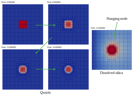
Figure 2.
Adaptive refinement around a square quartz region in a low silica concentration domain. A fixed low concentration silica source is present at the left boundary. The left-most four plots show how refinement and coarsening at successive times leads to more plausible shapes of alteration of the quartz block than would be obtained with a fixed grid. The corresponding silica solute concentration at the final time is shown in the right-hand plot. An example hanging node is also noted.
During refinement, neighboring cells in the grid can be refined different numbers of times. This results in nodes on the interfaces between cells that belong to a cell on only one side, which are referred to as ‘hanging nodes’. This can be seen in Figure 2. Since continuity of the solute species concentration across cells must be maintained, constraint equations are set at these nodes to ensure continuity. Essentially the solution at the hanging node is set to be an average of the concentrations at the neighboring nodes on the common interface, which would match the midpoint concentration of the Q1 element solution in the larger neighboring cell. The same simple averaging approach is used for all solute species, which includes both basis and complex species, which means that the mass action Equation (2b) is not expected to be satisfied at hanging nodes. This will lead to small errors with respect to the thermodynamic system in the computed aqueous species concentrations at hanging nodes, however this is not expected to impact greatly upon the overall solution and is acceptable given the added realism in the solution that is provided by the adaptive gridding.
The timing and location of cracks that appear in the modeled domain can be specified directly in the GARFIELD-CHEM input file or can be defined at run-time via OpenMI. Regardless of the way in which the cracks are specified, they are represented in the software as collections of crack legs that are connected at junctions, as shown in Figure 3. The crack model is separate from the grid used to simulate the porous media portions of the domain. Crack legs are allowed to bifurcate in the direction of flow, but not recombine. Each crack leg is piecewise linear, and within each leg a constant volumetric flow rate is assumed over each timestep. Crack flow rates can be updated at discrete times during the evolution of the system (again either via the input file or at run-time using OpenMI). Subscript index notation is used to indicate crack legs that bifurcate from preceding leg (where the index can itself be a tuple). Thus, the number of values in each index reflects the number of times that the crack pathway has bifurcated to reach the leg (minus one). For example, in the crack pathway illustrated in Figure 3, the pathway bifurcates twice before the crack leg is reached.
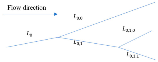
Figure 3.
Example fracture network showing bifurcation of an initial crack leg into subsequent crack legs.
If the volumetric flow rate in crack leg is (m3/s) and if the leg bifurcates into further legs, then the volumetric flow must be conserved across the junction, so:
GARFIELD-CHEM does not calculate flow rates and only checks that the relationship (6) is satisfied.
Solute fluxes between the finite volume crack model and porous media finite element grid model are represented in the software. The resulting interactions are expected to lead to alteration of minerals adjacent to the cracks, and so GARFIELD-CHEM automatically adapts the grid when cracks are imposed to resolve the crack locations to within a specified tolerance, . The grid adaption algorithm in this case is different to the front tracking algorithm discussed earlier and proceeds as follows. The crack pathway is overlaid on the grid and cells that the pathway intersects are identified, as shown in Figure 4. The cells intersected by the pathway are repeatedly refined until the cells that the crack intersects become sufficiently small; the cells are refined until
where (m) is the diameter of the cell (the largest diagonal of the cell), (m) is the width of the crack. The process results in successively refined cells closer to the crack, as shown in Figure 4.
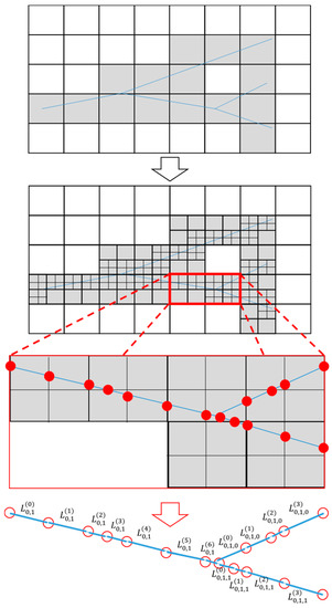
Figure 4.
Grid refinement and discretization of each crack pathway leg into segments. The cells intersected by the pathway are repeatedly refined until the cells that the crack intersects become sufficiently small. Each segment intersects only one grid cell.
The software allows separate set of media transport properties (i.e., diffusion coefficients) to be specified for cells that are ultimately intersected by cracks, in order to represent micro-cracking damage at scale below that which can be represented directly. These properties will ultimately control rates of transport between the crack and the grid cell, as discussed below.
Once the grid is refined to resolve the crack pathways to the required resolution, the crack pathway is refined into segments such that each segment intersects only one grid cell, as shown in Figure 4. The notation is used to indicate the th segment in the th crack leg (where is a tuple). The crack refinement algorithm proceeds by splitting each leg at the points where they intersect the grid cell boundaries to define the segments and then computes the length of each segment.
Advection of all solute species (basis and complex species) is modeled in the crack pathway, as well as thermodynamic equilibrium of complex species. No mineral dissolution/precipitation reactions are assumed to occur in the cracks, as discussed earlier. Instead, upscaled interactions are represented by crack-grid interactions in the cracked grid cells. Thus, in the cracks the system Equations (2a)–(2c) is solved, with .
The transport in the crack pathway is modeled using a finite volume approximation to simulate transport. In a given crack pathway segment, denoted with index , the transport of the th reactive basis species is given by
Here, (m3) is the volume of the crack segment with index (k = crack width × segment length × domain thickness, (m3/s) is the volumetric flow rate immediately upstream of the crack pathway segment with index , and denotes the collection of segments that are downstream of the segment with index (there can be more than one when the segment with index is the final segment in the leg before a bifurcation point), with denoting the downstream volumetric flow rate in each segment in . The term (mol/s) is a source/sink terms representing transfers between the grid and the crack segment with index , which is defined as follows.
By construction, each crack segment intersects a single grid cell, and therefore the source/sink term represents the transfer between a single grid cell and a single crack segment. The geometry of the interaction is sketched in Figure 5 for a single grid cell. The grid cell is assumed to have volume (m3) and to be intersected by a crack with width (m) with corresponding crack segment length (m).
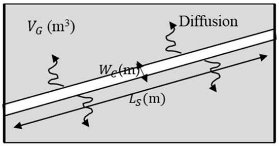
Figure 5.
Geometry of crack-grid transfer for a single grid cell with volume (m3) intersected by a crack of width (m) and segment length (m).
Transport between the crack and the grid is assumed to be diffusive, with diffusion coefficient controlled by the diffusive resistance of the media in the grid cell. The diffusive flux from the crack to the grid for a reactive chemical basis species is given by:
where (m2) is the crack surface area in the grid cell (= × domain thickness), (m2/s) is the diffusivity in the crack grid media, which depends on the grid cell porosity, , (m) is the diffusion length in the grid cell, and and (mol/kg) are the concentration of the th basis species and the th complex species in the segment and and (mol/kg) are the corresponding quantities in the grid cell. The diffusion length in the grid cell is taken to be the half of the grid cell diameter (which is equal to the length of the largest diagonal).
4. Effects of Chemical Alteration on Mechanical Parameters
4.1. Modeling in MACBECE
MACBECE [13,14,15] is capable of long-term mechanical analysis of various barrier materials, such as bentonite, metals, rocks and cement. It was developed to allow the effects of the mechanical alteration of the barrier materials on the long-term transitions of the hydraulic field of the near field to be inferred in order to develop more reliable safety assessment models. Cracks in cement materials in the TRU Gr 3/4 tunnel are expected to be generated mainly by corrosion swelling of metal materials, such as the steel containers surrounding the waste, and rock creep of the host formation. The connected crack pathway would strongly affect the water flow and the alteration behavior of cement materials.
For the rock materials, the variable compliance type constitutive model proposed by Okubo [25] was adopted to evaluate the rock creep.
Metal materials are modeled using corrosion swelling elements in MACBECE. The corrosion swelling is expressed by applying the swelling pressure to the metal element as equivalent nodal force. The swelling pressure of the metal materials is calculated from the corrosion swelling rate and the rigidity of the material. Since the actual corrosion occurs on the surface of the metal material, the swelling is assumed to be anisotropic, depending on the thickness of the metal member. Therefore, the corrosion swelling rate in MACBECE is given separately in horizontal and vertical directions to consider the anisotropic corrosion swelling (see Appendix A).
Cement materials are considered to deform due to external force from corrosion swelling of metal materials and rock creep, while reducing its rigidity and strength according to the progress of alteration such as porosity change and calcium leaching. To represent this behavior like strain softening, a nonlinear elasticity model (e.g., [26]) is included in the model.
The rotating crack model [27] and an iterative calculation method for stress redistribution are applied to calculate the strain softening behavior due to reduction of strength and rigidity associated with chemical alteration. In the rotating crack model, a crack occurs when the minimum principal stress of an element reaches tensile strength. The crack generation behavior and the change of mechanical properties due to the failure are expressed in the continuum elements by reducing the rigidity of the element in the direction perpendicular to the crack.
The deformation and the stress state at a time step in MACBECE are calculated by solving the balance of forces considering the material property changes. Chemical transitions of each barrier material that cause the change of the mechanical properties and the operating forces due to additional deformation in the materials are given as input data from other calculation software (i.e., GARFIELD-CHEM).
4.2. Modeling in DEAFRAP
DEAFRAP is a two-dimensional mechanical modeling application based on the discrete element method (DEM) [15]. The details of the fundamental DEM algorithm can be found in [9,28,29].
In DEAFRAP, an intact cement material is modeled as a dense packing of small rigid circular particles. Neighboring particles are bonded together at their contact points. If the normal tensile stress or shear stress acting on the cross-section of the bond exceeds the tensile strength or the shear strength, the bond breaks and tensile force never act on the contact point between two particles after the breakage unless the particles become reconnected due to subsequent chemical bonding. Individual bond breakage between bonded particles is defined as a microcrack. A microcrack is generated at the contact point between two particles. In 2D, the direction of a microcrack is perpendicular to the line joining the centres of the particles, and its aperture is calculated as the distance between the two particles. Neighboring microcracks may connect with each other and form a longer crack. These connected microcracks are defined as connected crack pathways in the DEAFRAP simulation.
4.3. Relation between MACBECE and DEAFRAP
The rotating crack model used in MACBECE does not recognize each crack individually because it models the behavior of the element containing the cracks as a continuum. In contrast, DEAFRAP can directly represent the grain-scale microstructural features of materials, such as pre-existing flaws, pores and microcracks. These microscale discontinuities induce complex macroscopic behaviors, such as crack generation, propagation, separation and merging, that are independent of complicated constitutive laws. However, the detailed crack analysis by DEAFRAP (and all DEM tools) can be time consuming, and so it is difficult to simulate the entire TRU Gr 3/4 EBS system in acceptable times. Therefore, based on the result of mechanical analysis by MACBECE, DEAFRAP is applied only to the region where the occurrence of cracks has been identified. The displacement calculated by MACBECE is given as the forced displacement to the outer boundary of the DEFRAP model.
Although DEAFRAP itself has no function to calculate chemical alteration such as porosity change, the temporal and spatial distribution of porosity obtained from GARFIELD-CHEM can be taken as input data. From the particle arrangement of the DEAFRAP model, the continuous porosity distribution is converted to the porosity of each particle. The rigidity and strength of bonded particles are changed according to the porosity. The relationship between porosity and mechanical parameters in DEAFRAP is calibrated to be consistent with that in MACBECE.
In an actual cement material, it can be considered that generated cracks may become filled by mineral precipitation and the cracks repaired by the solidification over time. To represent this phenomenon, the porosity at the crack position is recorded at the time of bond breakage in DEAFRAP. The crack is repaired, and the particles are reconnected when the value of porosity reduction at that position reaches a specified value.
5. Application to TRU Gr3/4
5.1. GARFIELD-CHEM Model
The disposal tunnels in the example application of the TRU Gr 3/4 design feature a large cementitious backfill, whose main function in the safety case is to condition the porewater at a high pH to inhibit corrosion of the steel containers surrounding the waste, and to provide mechanical load-bearing capacity. The backfill is expected to exhibit self-sealing capabilities and to limit radionuclide leaching and transport through sorption, following late-time failure of the metal waste containers. The concrete backfill is expected to provide some capacity to limit the rate of groundwater flow, and hence the release rate of radionuclides after failure of the containers. However, there is a current lack of understanding of the processes governing its long-term degradation and so the potentially low permeability of the backfill is not explicitly accounted for in the current safety case. where it is treated pessimistically, by considering it as a porous media with a permeability similar to sand [12]. A better understanding of the degradation process may allow this pessimistic simplification to be made more realistic in future safety analyses.
The simple geological repository design for transuranic (TRU) waste based on the Japanese disposal concept [12] is shown in Figure 6. The backfill, invert, inner liner and outer liner components are all cementitious, with mineral compositions as shown in Table 1.
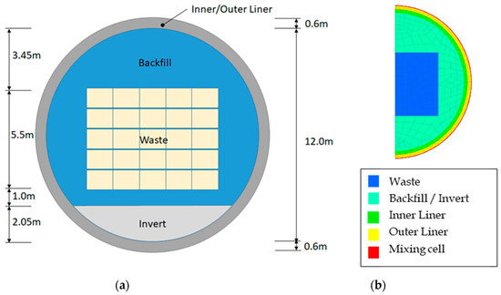
Figure 6.
Cross-section of the TRU Gr 3/4 tunnel design (a) and half system that is modeled with GARFIELD-CHEM, showing the initially coarse grid at t = 0 year (b). The grid is constructed using quadrilateral elements and was computed using GMSH [30].

Table 1.
Composition of cementitious features in the model. Minerals with zero initial concentration in the materials are treated as potential secondary minerals.
Thermodynamic parameters used in the modeling of the Gr 3/4 EBS materials in GARFIELD-CHEM are described in Appendix A.
The initial porewater in all tunnel materials was assumed to be identical, with composition as shown in Table 2. This composition was obtained assuming that fresh, reducing high pH (FRHP) groundwater [31] is in equilibrium with the cement material. External water compositions are also shown in Table 2 and were assumed to be present at the outer boundary, and at the upstream end of any cracks that emerge in the system and were obtained by equilibrating FRHP groundwater with calcite.

Table 2.
Water compositions. The external water is based on a calcite-equilibrated calculation with FRHP water [31] and the initial porewater is equilibrated with the cement material for Backfill (Table 1).
The external water is not applied directly to the tunnel boundary, since the in situ porewater at the boundary will arise as a consequence of mixing between the cementitious water diffusing from the tunnel and the host rock groundwater. Directly applying a host rock water on the tunnel boundary would therefore be too ‘aggressive’ in terms of the chemical alteration that can be expected in the liner regions. A mixing cell condition is therefore applied adjacent to the tunnel boundary, where the two waters are allowed to react. A turnover flow rate of host rock groundwater of m/s is assumed, corresponding to an assumed head gradient of m/m perpendicular to the modeled domain, and a hydraulic conductvity of the (engineering damaged) rock region adjacent to the tunnel of m/s (defined as 100 times larger than that of host rock). The mixing region has a width of 50 mm.
The parameterization of effective diffusivity (Equation (4)) used in the model is shown in Table 3. is a cementation exponent and models how the pore network affects diffusivity. A separate parameterization of the diffusivity model is used in cells that contain cracks. This allows the effect of micro-cracks, that are below the scale of the dominant cracks that are modeled, to enhance diffusion.

Table 3.
Transport properties.
The diffusion model can be overridden at run-time via OpenMI, allowing MACBECE to specify an effective diffusivity based on a combination of the degree of chemical alteration and on the computed mechanical displacement.
The strain-porosity component model for cement materials is shown in Figure 7. θc [-] is the porosity value calculated by GARFIELD-CHEM (i.e., ), εv [-] is a volumetric strain (positive value for compression). The model assumes that aggregate material is incompressible so that the porosity value after distortion (θ’c) can be calculated as follows,

Figure 7.
Strain-porosity component model for cement materials. is the total porosity calculated in GARFIELD-CHEM, is the percentage volume occupied by incompressible aggregate (non-porous) and is the corresponding porosity in the porous media fraction of the total volume. After volumetric strain is applied, porous media components are distorted and total porosity and porous media porosity are reduced, while the aggregate volume remains constant.
The θ’c value is used in GARFIELD-CHEM to recalculate the effective diffusion coefficient using Archie’s law (Equation (4)).
For the analysis shown in Section 6, mechanical distortions were found to account for less than 1% of the total porosity. Since this has a negligible effect on the effective diffusion, the coupling to update based on the mechanical evolution was omitted from the model to simplify the coupling in the current analysis. However, it can be reintroduced easily if it is found to be more significant in future applications.
The TRU Gr 3/4 tunnel geometry (Figure 6) was modeled as a half-system, assuming symmetry about the vertical axis. The initial grid that is used, which was computed using GMSH [30], is shown in Figure 6. The initial grid is intentionally coarse, with some cell sizes being tens of centimetres. As cracks appear, automatic grid refinement around the crack locations will lead to a finer grid in regions that are expected to undergo the most alteration, thus focussing computational effort in the regions of greatest relevance to potential pathways for long-term radionuclide transport.
5.2. MACBECE Model
The domain considered in the MACBECE stress analysis model of the TRU Gr 3/4 tunnel is shown in Figure 8. To represent the evolving stresses and displacements in the tunnel system it is necessary to include a large region of host rock surrounding the tunnel, and also to represent the internal structures in the waste form. The grid used in the tunnel region is also shown in Figure 8. A combination of quadrilateral and triangular elements is used in the finite element model.
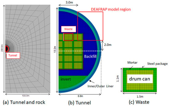
Figure 8.
Whole model of the TRU Gr3/4 tunnel. The grid is constructed using quadrilateral and triangular elements. (a) Simulated tunnel and rock grid, (b) Zoomed view showing tunnel grid, (c) Zoomed view showing waste grid.
The analysis conditions and parameters used in the MACBECE model are described in Appendix A.
5.3. DEAFRAP Model
The analysis conditions of DEAFRAP are based on a case presented in [32]. That analysis aimed to simulate crack generation for the whole-tunnel (Figure 8) and did not consider any direct coupling to a chemical process model. In the modeling presented here, the domain considered by DEAFRAP is not the whole tunnel, but is instead a “corner” region of the tunnel (Figure 9). This corner region is identified by MACBECE, in the coupled loop with GARFIELD-CHEM, as being the region in which the density of cracking is expected to be greatest. Further details are given in Section 6.1.
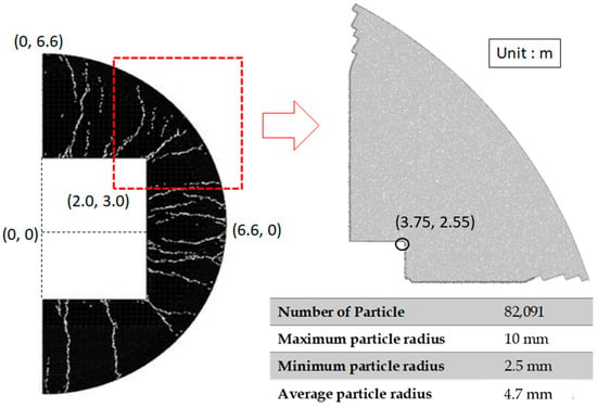
Figure 9.
An example of DEAFRAP analysis for half tunnel (extraction of continuum cracks, left (from [32])) and DEAFRAP system for coupled analysis, showing DEAFRAP particle properties (right).
In the DEAFRAP analysis, displacement data on the boundary must be imposed. These data are derived from the MACBECE analysis. The mechanical parameters for each material is the same as for the MACBECE analysis (Section 5.2). The treatment of chemical alteration information in DEAFRAP is also the same as for MACBECE, that is, the porosity values calculated by GARFIELD-CHEM are assigned to the corresponding DEM particles.
Figure 9 provides details of the number of DEM particles in the DEAFRAP model and their dimensions.
6. Results
Results of a preliminary application of the coupled modeling framework are presented. The results cover the period up to identification of the first crack that fully penetrates the backfill, and a 2000 years period thereafter.
6.1. Before Cracking
6.1.1. Chemical Alteration
In this section, results are shown for the period up to 10,000 years. As will subsequently be explained, full penetration of cracks from the waste region to the host rock was found to occur at 10,000 years, and so the results in this section describe the evolution of the TRU Gr 3/4 system prior to cracking.
Prior to cracking, reactive transport within the system is diffusion-limited and so the most significant alteration is expected to occur at the interface between the tunnel and the host rock, where the largest porewater chemistry gradients are present. This can be seen in Figure 10, which shows profiles of calcite, CSH165 (the primary C-S-H phase with ratio Ca/Si = 1.65) and portlandite at 0 and 10,000 years. A front of calcite, which is initially assumed to not be present in the cement regions, precipitates to a depth of 0.15 m due to the supply of carbonate-rich water from the host rock. Calcium for the calcite precipitation is mostly liberated from portlandite dissolution and a smaller amount of CSH165 dissolution, due to the lower pH of the host rock pore water. Portlandite is dissolved beyond the calcite precipitation front, to a depth of 0.30 m, with corresponding precipitation of CSH165 in the region. This alteration is uniform along the boundary with the host rock, as would be expected due to the symmetry of the boundary conditions.
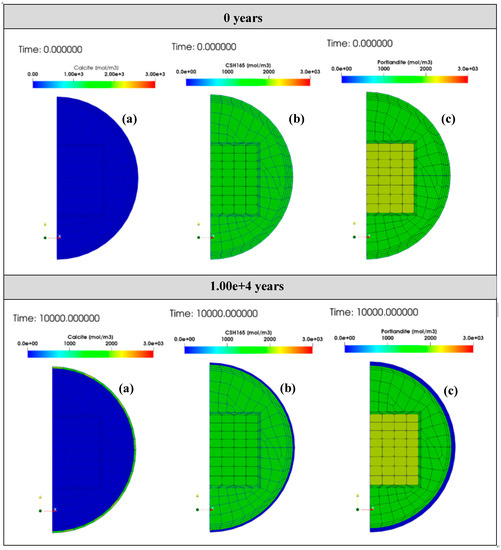
Figure 10.
Profiles at 0 years (top) and 10,000 years (bottom) of: (a) calcite, (b) C-S-H 165 and (c) portlandite.
6.1.2. Porosity Alteration (Chemical) and Effective Diffusion Coefficients
Profiles of porosity and effective diffusion at 0 and 10,000 years are shown in Figure 11. The porosity alteration is calculated purely from chemical alteration (dissolution and precipitation of minerals) by GARFIELD-CHEM; mechanical displacements are not considered. As mentioned in Section 5.1, the coupling of the effective diffusion to mechanical displacement was not considered because the mechanical distortion effect accounts for less than 1% of porosity. Therefore, all porosity evolution in the current analysis arises purely as a consequence of chemical alteration.
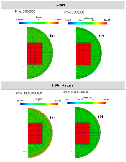
Figure 11.
Profiles at 0 years (top) and 10,000 years (bottom) of porosity (a) due to chemical alteration calculated by GARFIELD-CHEM, and effective diffusion coefficients (b).
By 10,000 years, the porosity value in the outermost 0.15 m is increased from 13% to ~20%, due to the portlandite dissolution. As noted above, calcite precipitation occurs in this region, but the net effect of the alteration is to increase the porosity. The porosity in the region from 0.15–0.30 m is decreased by ~4%, due to the precipitation of CSH165.
6.1.3. Crack Distribution
Crack aperture distributions calculated with MACBECE at 5000 and 10,000 years are shown in Figure 12. The crack aperture calculation assumes that calculated distortions result in a single crack per cell. The plots are repeated with the maximum value on the crack aperture scale set to 1 mm and 0.1 mm (i.e., cracks with apertures larger than this size are shown at the maximum plotted aperture). The cracks concentrate in the North-East corner region, with some cracks appearing to fully penetrate the backfill region by 10,000 years. Therefore, the corner region at 10,000 years is selected as a region for detailed cracking analysis with DEAFRAP.
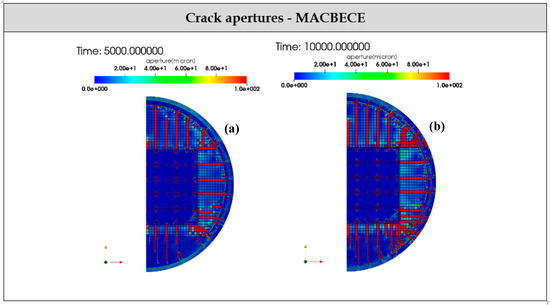
Figure 12.
Distributions of crack apertures obtained with MACBECE with a maximum plotted aperture of 0.1 mm at 5000 years (a) and 10,000 years (b). Cracks with apertures larger than 0.1 mm appear to penetrate the backfill by 10,000 years.
The corresponding DEAFRAP analysis is shown in Figure 13. Again, plots are shown with maximum plotted crack apertures of 1 mm and 0.1 mm. The DEAFRAP results confirm that fully penetrating cracks are expected by 10,000 years and identifies potential cracking patterns and pathways. Extraction of continuous crack pathways from the model is discussed in the next section.
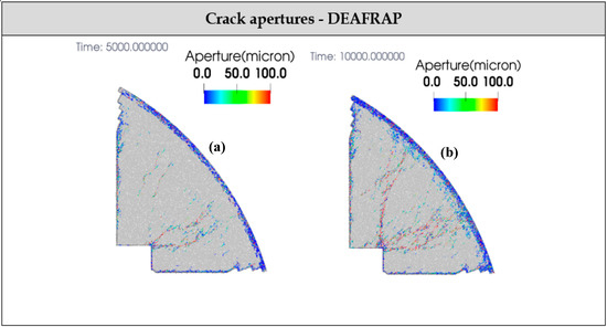
Figure 13.
Distributions of crack apertures obtained with DEAFRAP with a maximum plotted aperture of 0.1 mm at 5000 years (a) and 10,000 years (b). Cracks with apertures larger than 0.1 mm appear to penetrate the backfill by 10,000 years.
The corresponding DEAFRAP analysis is shown in Figure 13. Again, plots are shown with maximum plotted crack apertures of 1 mm and 0.1 mm. The DEAFRAP results confirm that fully penetrating cracks are expected by 10,000 years and identifies potential cracking patterns and pathways. Extraction of continuous crack pathways from the model is discussed in the next section.
6.1.4. Extraction of Backfill-Spanning Cracks
Using the result of the DEAFRAP cracking analysis, a continuous crack pathway from the waste form that fully penetrates the backfill region is identified. The extracted crack is shown in Figure 14. The aperture of the crack identified in the analysis is taken to be 0.89 mm, as the 99th percentile value of the selected continuous cracks.
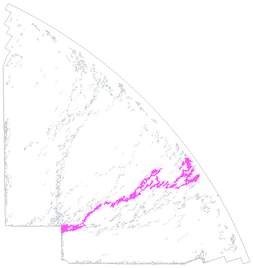
Figure 14.
Extracted continuous crack that spans the backfill, from the waste to the host rock boundary.
In the current version of the modeling system, identification of the crack pathway is performed using a separate script that identifies connected crack sections to form an overall path from the waste region to the outer boundary.
6.2. After Cracking
6.2.1. Hydraulic Analysis
Since a half-system is modeled by symmetry it is assumed that once a crack pathway is identified that joins the waste region to the host rock, an analogous pathway will join the waste to host rock on the other side of the tunnel, which is assumed to be the upstream side. Advective conditions will then arise in the model, with water flowing through the cracks in the half of the system that is modeled.
Using the extracted crack geometry, a hydraulic analysis is carried out using the FEMWATER v3.0.5 software [33] to solve for the saturated flow conditions in the tunnel taking into account the separate permeabilities of the waste, cement, EDZ and rock regions in the domain. The transmissivity [m2/s] of the crack is calculated from the crack aperture using the cubic law arising from assuming Poiseuille flow conditions in the crack [34],
where (kg/m3) is the fluid density, (m/s2) is gravitational acceleration, (Pa s) is viscosity, and 2b (m) is the crack aperture.
6.2.2. Mesh Refinement after Cracking
In order to continue the coupled analysis between GARFIELD-CHEM and MACBECE following identification of the crack, the crack pathway location, aperture and volumetric flow rate are passed to GARFIELD-CHEM. The parameters are summarized in Table 4.

Table 4.
Summary of crack parameters passed to GARFIELD-CHEM following the DEAFRAP and FEMWATER analysis.
The volumetric flow rate is obtained in the separate analysis described above. The crack in the half of the domain that is modeled provides a transport pathway from the waste to the host rock. The flow rate through the pathway from the hydraulic analysis determines the volumetric flux that is applied in the GARFIELD crack model.
Figure 15 shows the GARFIELD-CHEM grid after refinement for the crack information summarized in Table 4. Note that the grid cells around the cracks are refined until the size of the “cracked cell” is smaller than 0.114 m (100 times larger than the crack aperture). This choice of scaling factor will control the accuracy of the diffusive transfers between the finite volume crack model in GARFIELD-CHEM (in which the precise crack geometry and aperture is used) and the porous media grid, and will also control the number of grid cells that arise, and therefore the numerical complexity. The actual cell size depends on the shape of the neighboring cells, and in this example application the size of the cracked cells is mostly a few centimeters.
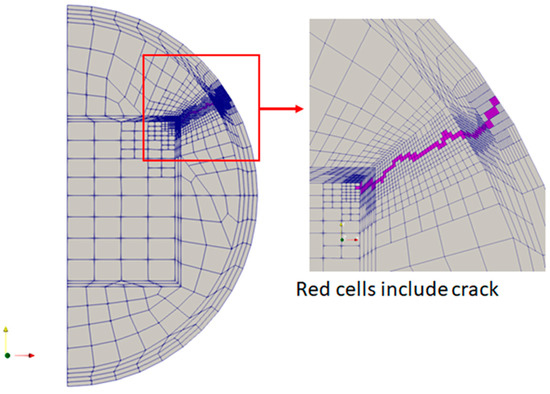
Figure 15.
GARFIELD-CHEM refined mesh after cracking.
The water composition at entry points to the crack pathway is the same as the “External Water” in Table 2. Therefore, it is assumed that fresh water flows directly into the crack pathway, conservatively ignoring any cement buffering in the upstream half of the tunnel.
6.2.3. Chemical Alteration
Preliminary results of the subsequent reactive transport and alteration following the appearance of the crack are shown in Figure 16; Figure 17 at 12,000 years (2000 years after appearance of the crack). The grid outline has been removed in these figures to aid visibility. The corresponding grid can be seen in Figure 15. A front of portlandite dissolution emanates from the waste form (Figure 16b), where the fresh water enters the cementitious backfill and reaches a depth of approximately 10 cm into the matrix. A corresponding calcite precipitation pattern is seen (Figure 16d), whose extent into the cement matrix is not as extensive as the portlandite dissolution front (analogous to the portlandite dissolution front that emerged at the interface between the tunnel liner and the host rock in the early evolution, Section 6.1). CSH165 is largely unchanged during the 2000 years period (Figure 16c), in contrast to the early evolution when CSH165 precipitation in advance of the calcite front was seen. This is possibly a consequence of the reduced availability of the more rapid removal of cementitious water along the advective crack pathway compared to the diffusive mixing at the tunnel liner interface with the rock in the early evolution. pH is not significantly reduced and only falls by ~0.2 close to the waste form (Figure 16e).
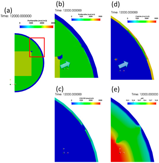
Figure 16.
Portlandite (a) and its zoomed profile (b), at 12,000 years (2000 years after crack appearance), corresponding CSH165 (c) profile, calcite profile (d), and pH profile (e).
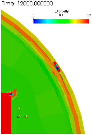
Figure 17.
Porosity profile at 12,000 years (2000 years after crack appearance).
6.2.4. Porosity Alteration (Chemical)
Figure 17 shows the porosity distribution at 12,000 years (2000 years after the appearance of the crack). In the vicinity of the waste region, the porosity close to the crack pathway is only marginally reduced, since the porosity increase arising from the portlandite dissolution is mostly compensated for by precipitation of calcite. Deeper into the matrix there is a net porosity increase surrounding the crack pathway where portlandite dissolution has occurred without any compensating mineral precipitation.
7. Conclusions
Modeling of coupled processes associated with geological disposal concepts for radioactive waste is complicated by the fact that it is difficult to include all relevant processes in a single simulation code. There is a large body of existing simulation software that is used in radioactive waste assessment modeling that is tailored to modeling one or a small number of physical processes, but different numerical approaches to discretization, different gridding strategies and resolutions and different numerical time stepping methods are often used to simulate the processes. Ideally, some method of combining these existing tailored codes would be available to allow coupled models of systems of interest to be formed.
An approach to developing simulators for geological disposal concepts by coupling existing modeling software has been presented that uses the OpenMI standard to allow exchange of data between models at run-time. Existing mechanical models, MACBECE and DEAFRAP, have been coupled to a new reactive transport simulator, GARFIELD-CHEM, that incorporates both a finite element component for simulating reactive transport in a porous media grid and a coupled finite volume crack network model component, with grid refinement allowing cracked regions to be more finely resolved. GARFIELD-CHEM and MACBECE are coupled tightly in an OpenMI loop to allow parametric dependence of mechanical properties on the degree chemical degradation (characterized by the degree of porosity alteration and mineral leaching) and chemical properties on the degree of mechanical alteration (characterized by the dependence of effective diffusion on displacements) to be represented. DEAFRAP is used to assess cracking patterns when the stresses and displacements calculated by MACBECE are expected to be sufficient to lead to cracking, or assess growth of existing cracks, and the resultant cracking patterns are used to define crack networks that are subsequently imposed in GARFIELD-CHEM before the tightly coupled chemical-mechanical model is resumed. The resulting coupled model allows the chemical-mechanical-mass transport feedbacks that control the onset and development of cracking of the cement backfill to be simulated.
The benefits of combining existing detailed simulation software with OpenMI to construct detailed coupled system models, which do not rely on significant simplifications that might be necessary to combine all of the modeled processes in a single piece of software, has been demonstrated by simulating the cracking of the cement backfill in the Gr 3/4 concept based on the Japanese disposal concept for disposal of TRU waste [12]. Preliminary results are presented that demonstrate the effect of the coupling up to and beyond the onset of cracking. Further application will be undertaken in future to simulate the effect of the cracking over the entire assessment period to attempt to better understand the nature of the backfill degradation process. It is hoped that such analysis will allow greater realism in future assessments by better representing the potentially beneficial properties of cement barriers, as opposed to their pessimistic treatment in historical safety cases.
The coupling approach using OpenMI is generic and potentially has wider application in the radioactive waste modeling community for combining existing software to form coupled models of systems of relevance in order to help to understand the effects of couplings that would otherwise be difficult or expensive to represent in a single computer model.
Author Contributions
Conceptualization, S.J.B., D.K., H.T., H.S., C.O., F.H., Y.T., M.M. and A.H.; Formal analysis, S.J.B., D.K. and H.S.; Investigation, S.J.B., D.K., H.S. and C.O.; Methodology, S.J.B., D.K., H.T. and H.S.; Software, S.J.B., D.K. and H.S.; Validation, S.J.B., D.K. and H.S.; Visualization, S.J.B. and D.K.; Writing—original draft, S.J.B. and D.K.; Writing—review & editing, S.J.B., D.K., H.T., C.O., F.H., Y.T., M.M. and A.H. All authors have read and agreed to the published version of the manuscript.
Funding
This research was funded by the Ministry of Economy, Trade and Industry of Japan, grant name “The project for validating assessment methodology in geological disposal system (JFY2017)”.
Conflicts of Interest
The authors declare no conflict of interest.
Appendix A
Appendix A.1. Thermodynamic Parameters for GARFIELD-CHEM Analysis
Primary and secondary mineral thermodynamic data used in GARFIELD-CHEM simulations is given in Table A1. All minerals are simulated kinetically using TST reactions, parameterized as shown in Table A1. The porewaters throughout the domain were modeled as a Ca-CO3-Si-Mg system, using thermodynamic data as shown in Table A2. The modeled chemical system is intentionally a simplified one, since the primary aim of the modeling is to test the approach to coupling the various models. It is hoped that more comprehensive chemical systems may be included in future work.

Table A1.
Thermodynamic, molar volume and kinetic rate data for primary and secondary cement minerals. All data is taken from JAEA-TDB v1.07 [35].
Table A1.
Thermodynamic, molar volume and kinetic rate data for primary and secondary cement minerals. All data is taken from JAEA-TDB v1.07 [35].
| Mineral | Reaction | Molar Volume (cc/mol) | Log K (25 °C) | Reaction Rate (mol m−2 s−1) | Specific Surface Area (m2/g) |
|---|---|---|---|---|---|
| Brucite | 24.630 | 17.1018 | 5.75 × 10⁻¹⁷ | 10 | |
| Calcite | 36.934 | 1.8487 | 6.30 × 10⁻⁶ | 0.02 | |
| CSH165 | 77.406 | 28.8407 | 3.63 × 10⁻⁹ | 22.43 | |
| CSH105 | 62.131 | 15.4797 | 1.10 × 10⁻¹¹ | 62.48 | |
| Portlandite | 33.060 | 22.8002 | 1.00 × 10⁻⁶ | 10.44 |

Table A2.
Thermodynamic data for complex solute species. Basis species the model are , , , , and . All thermodynamic data is taken from JAEA-TDB v1.07 [35].
Table A2.
Thermodynamic data for complex solute species. Basis species the model are , , , , and . All thermodynamic data is taken from JAEA-TDB v1.07 [35].
| Aqueous Species | Reaction | Log K (25 °C) |
|---|---|---|
| 13.9951 | ||
| 7.0017 | ||
| 12.8501 | ||
| −1.0467 | ||
| −6.3813 | ||
| 10.3288 | ||
| −1.0357 | ||
| 7.3499 | ||
| 11.6795 | ||
| 8.6998 | ||
| 19.0646 | ||
| 9.8096 | ||
| 23.1701 |
Appendix A.2. Parameters for MACBECE Analysis
Appendix A.2.1. Specifications of Cement Materials
The mechanical analysis parameters are based the “Second Progress Report on Research and Development for TRU Waste Disposal in Japan” [12]. The assumed specification and detailed properties of the cement materials are summarized in Table A3 and Table A4.

Table A3.
Assumed specifications for cement components (from [12]).
Table A3.
Assumed specifications for cement components (from [12]).
| Component | Material | Aggregate Ratio | Porosity | Real Density (g/cm3) | Compressive Strength (MPa) |
|---|---|---|---|---|---|
| Inner Liner, Outer Liner, Invert, Backfill | Concrete (W/C = 45%) | 67 vol% | 13% | 2.62 | 43 |
| Waste | Mortar (W/C = 55%) | 54 vol% | 19% | 2.58 | 35 |

Table A4.
Properties for cement components.
Table A4.
Properties for cement components.
| Property | Inner Liner/Outer Liner/ Invert/Backfill | Waste |
|---|---|---|
| Initial Young’s modulus E0 (MPa) | 3.04 × 10⁴ | 1.75 × 10⁴ |
| Poisson ratio ν(−) [before yield] | 0.20 | 0.20 |
| [after yield] | 0.45 | 0.45 |
| Effective overburden pressure σvi’ (Mpa) | Obtained by deadweight calculation | |
| Coefficient of earth pressure at rest Ki (−) | Obtained by deadweight calculation | |
| Initial elastic shear modulus G0(MPa) | G0 = E0/2(1 + ν) | |
| Initial adhesive force c0 (MPa) | 21.5 | 17.5 |
| internal frictional angle φ (deg.) | 0 | 0 |
| Initial compressive strength σc0 (MPa) | 43 | 35 |
| Minimum compressive strength σc min (MPa) | 0.43 | 0.35 |
| Air dried weight of unit volume γ (kN/m3) | 22.8 | 20.9 |
| Initial tensile strength σt (MPa) | 4.3 | 3.5 |
| Minimum tensile strength σt min (MPa) | 0.043 | 0.035 |
| Rigidity reduction ratio after cracking (−) | 1/100 | 1/100 |
| Water viscosity (m2/s) | 1.0 × 10⁻⁶ | 1.0 × 10⁻⁶ |
| Number of cracks per element | 1.0 | 1.0 |
Appendix A.2.2. Properties of Metal Materials
Analysis parameters for metal materials (treated as corrosion swelling elements) are summarized in Table A5.

Table A5.
Properties for metal materials.
Table A5.
Properties for metal materials.
| Waste (Steel Package) | Waste (Drum Can) | |
|---|---|---|
| Corrosion swelling ratio β (−) | 3.2 | |
| Rigidity (sound region) E0 (MPa) | 211,400 | |
| Rigidity (corroded region) Ecor (MPa) | 250 | |
| Poisson ratio ν (−) | 0.333 | |
Appendix A.3. Relation between Corrosion Swelling Rate and Distortion Increasing Rate
The distortion increasing rate for the and directions can be described as follows (see Figure A1).
where is the corrosion swelling rate (m/year) and () is the thickness of the metal part (m). The corrosion swelling rate can be represented as
where is the corrosion rate (m/y) and is the corrosion swelling ratio (treated as a magnification). The assumed corrosion rate is 0.04 µm/y (considering the corrosion of both sides: [36]) and the assumed corrosion swelling ratio is 3.2 [36], so that (m/y).
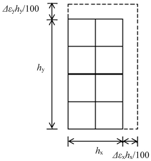
Figure A1.
Distortion increasing rate.
Appendix A.4. Distortion Increasing Rate for Steel Packages
The dimensions of the steel packages and drum can are shown in Figure A2. The left figure shows a half of the cross section, and the red circled numbers correspond to the ID number shown in Table A6, which lists the distortion increasing rate at the various locations on the surface of the package.
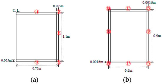
Figure A2.
The shape of steel package (a) and drum can (b) [12].

Table A6.
Distortion increasing rate for the steel packages. γ represents corrosion swelling rate.
Table A6.
Distortion increasing rate for the steel packages. γ represents corrosion swelling rate.
| Number | Δεx (%/Year) | Δεy (%/Year) |
|---|---|---|
| 14 | 100γ/hx = 66.667γ (hx = 0.75 × 2) | 100γ/hy = 20000γ (hy = 0.005) |
| 15 | 100γ/hx = 20000γ (hx = 0.005) | 100γ/hy = 90.909γ (hy = 1.1) |
| 16 | 100γ/hx = 66.667γ (hx = 0.75 × 2) | 100γ/hy = 90.909γ (hy = 1.1) |
| 17 | 100γ/hx = 166.667γ (hx = 0.6) | 100γ/hy = 62500γ (hy = 0.0016) |
| 18 | 100γ/hx = 62500γ (hx = 0.0016) | 100γ/hy = 111.111γ (hy = 0.9) |
| 19 | 100γ/hx = 166.667γ (hx = 0.6) | 100γ/hy = 111.111γ (hy = 0.9) |
Properties for the Rock Material
The mechanical analysis parameters for the rock material are based on those for the “SR-C” (soft rock) in [12]. The assumed rock property values are summarized in Table A7. The initial overburden pressure and lateral pressure coefficient assume a repository depth of 500 m. The Ohkubo model [25] was used as the stress-distortion relation model.

Table A7.
Properties for the rock materials (nonlinear viscoelasticity).
Table A7.
Properties for the rock materials (nonlinear viscoelasticity).
| Property | Value |
|---|---|
| Unit weight γt (kN/m3) | 22.0 |
| Uniaxial compressive strength qu (MPa) | 15.0 |
| Tensile strength σt (MPa) | 2.1 |
| Initial Young’s modulus E0 (MPa) | 3.50 × 10³ |
| Initial Poisson ratio ν0 (−) | 0.30 |
| Initial overburden pressure σvi (MPa) | 11.0 |
| Lateral pressure coefficient Ki (−) | 1.066 |
References
- Carter, A.; Kelly, M.; Bailey, L. Radioactive high level waste insight modelling for geological disposal facilities. Phys. Chem. Earth Parts A/B/C 2013, 64, 1–11. [Google Scholar] [CrossRef]
- Parkhurst, D.L.; Appelo, C. Description of Input and Examples for PHREEQC Version 3: A Computer Program for Speciation, Batch-Reaction, One-Dimensional Transport, and Inverse Geochemical Calculations; Techniques and Methods; U.S. Geological Survey: Denver, CO, USA, 2013.
- Lichtner, P.C.; Hammond, G.E.; Lu, C.; Karra, S.; Bisht, G.; Andre, B.; Mills, R.T.; Kumar, J. PFLOTRAN User Manual: A Massively Parallel Reactive Flow and Transport Model for Describing Surface and Subsurface Processes; Office of Scientific and Technical Information (OSTI): Oak Ridge, TN, USA, 2015. [CrossRef]
- Bethke, C.M.; Farrell, B.; Yeakel, S. The Geochemist’s Workbench, Version 12.0: GWB Essentials Guide; Aqueous Solutions, LLC.: Champaign, IL, USA, 2018. [Google Scholar]
- Hibbitt, D.; Karlsson, B.; Sorensen, P. ABAQUS/CAE User’s Manual, 6.11; Simulia Corp.: Johnston, RI, USA, 2013. [Google Scholar]
- COMSOL Multiphysics® v. 5.4. www.comsol.com; COMSOL AB: Stockholm, Sweden, 2018.
- Eymard, R.; Gallouët, T.; Herbin, R. Finite volume methods. In Handbook of Numerical Analysis; Ciarlet, P.G., Lions, J.L., Eds.; Elsevier: Amsterdam, The Netherlands, 1997; Volume 7, pp. 713–1018. [Google Scholar] [CrossRef]
- Johnson, C. Numerical Solution of Partial Differential Equations by the Finite Element Method. Math. Comput. 1989, 52, 247. [Google Scholar] [CrossRef]
- Shimizu, H.; Murata, S.; Ishida, T. The distinct element analysis for hydraulic fracturing in hard rock considering fluid viscosity and particle size distribution. Int. J. Rock Mech. Min. Sci. 2011, 48, 712–727. [Google Scholar] [CrossRef]
- Tryggvason, G.; Bunner, B.; Esmaeeli, A.; Jurič, D.; Al-Rawahi, N.; Tauber, W.; Han, J.; Nas, S.; Jan, Y.-J. A Front-Tracking Method for the Computations of Multiphase Flow. J. Comput. Phys. 2001, 169, 708–759. [Google Scholar] [CrossRef]
- Gregersen, J.B.; Gijsbers, P.J.A.; Westen, S.J.P. OpenMI: Open modelling interface. J. Hydroinform. 2007, 9, 175–191. [Google Scholar] [CrossRef]
- JAEA; FEPC. Second Progress Report on Research and Development for TRU Waste Disposal in Japan—Repository Design, Safety Assessment and Means of Implementation in the Generic Phase—, JAEA-Review 2007-010; FEPC TRU-TR2-2007-01, Technical Report; Japan Atomic Energy Agency (JAEA): Tokai, Ibaraki, Japan; The Federation of Electric Power Companies Japan (FEPC): Chiyoda, Tokyo, Japan, 2007. [Google Scholar]
- Ohno, S.; Morikawa, S.; Mihara, M. The Rock Creep Evaluation in the Analysis System for the Long-Term Behavior of TRU Waste Disposal System. In Proceedings of the ASME 2009 12th International Conference on Environmental Remediation and Radioactive Waste Management, Liverpool, UK, 11–15 October 2009; Volume 2, pp. 291–297. [Google Scholar]
- Mihara, M.; Hirano, F.; Takayama, Y.; Kyokawa, H.; Ohno, S. Long-term mechanical analysis code considering chemical alteration for a TRU waste geological repository. Genshiryoku Bakkuendo Kenkyu (Internet) 2017, 24, 15–25. [Google Scholar]
- JAEA. The Project for Validating Assessment Methodology in Geological Disposal System; Summary Report for JFY2013-2017; Japan Atomic Energy Agency (JAEA): Tokai, Ibaraki, Japan, 2018. (In Japanese) [Google Scholar]
- Moore, R.; Gijsbers, P.; Fortune, D.; Gergersen, J.; Blind, M. OpenMI Document Series: Part A Scope for the OpenMI (Version 1.4). IT Frameworks (HarmonIT) Contract EVK1-CT-2001-00090. Available online: https://www.openmi.org/openmi-around-the-world/development-tools (accessed on 28 August 2020).
- Steefel, C.I.; Appelo, C.A.J.; Arora, B.; Jacques, D.; Kalbacher, T.; Kolditz, O.; Lagneau, V.; Lichtner, P.C.; Mayer, K.U.; Meeussen, J.C.L.; et al. Reactive transport codes for subsurface environmental simulation. Comput. Geosci. 2014, 19, 445–478. [Google Scholar] [CrossRef]
- Zhu, C.; Anderson, G. Environmental Applications of Geochemical Modeling; Cambridge University Press: Cambridge, UK, 2002. [Google Scholar]
- Bethke, C.M. Geochemical and Biogeochemical Reaction Modeling; Cambridge University Press: Cambridge, UK, 2007. [Google Scholar] [CrossRef]
- Pitzer, K.S. Activity Coefficients in Electrolyte Solutions, 2nd ed.; CRC Press: Boca Raton, FL, USA, 1991. [Google Scholar]
- Archie, G. The Electrical Resistivity Log as an Aid in Determining Some Reservoir Characteristics. Trans. AIME 1942, 146, 54–62. [Google Scholar] [CrossRef]
- Hindmarsh, A.C.; Brown, P.N.; Grant, K.E.; Lee, S.L.; Serban, R.; Shumaker, D.E.; Woodward, C.S. SUNDIALS, suite of nonlinear and differential/algebraic equation solvers. ACMTrans. Math. Softw. 2005, 31, 363–396. [Google Scholar] [CrossRef]
- Wilson, J.C.; Benbow, S.; Metcalfe, R. Reactive transport modelling of a cement backfill for radioactive waste disposal. Cem. Concr. Res. 2018, 111, 81–93. [Google Scholar] [CrossRef]
- Arndt, D.; Bangerth, W.; Clevenger, T.C.; Davydov, D.; Fehling, M.; Garcia-Sanchez, D.; Harper, G.; Heister, T.; Heltai, L.; Kronbichler, M.; et al. The deal.II library, Version 9.1. J. Numer. Math. 2019, 27, 203–213. [Google Scholar] [CrossRef]
- Okubo, S. Analytical Consideration of Constitutive Equation of Variable Compliance Type. Shigen-to-Sozai 1992, 108, 601–606. [Google Scholar] [CrossRef]
- Motojima, M.; Kitahara, Y.; Ito, H. The Stability of Rock Foundation with Considering Strain-Softening Material; CRIEPI Technical Report; Central Research Institute of Electric Power Industry (CRIEPI): Tokyo, Japan, 1981. (In Japanese) [Google Scholar]
- Rots, J. Computational Modelling of Concrete Fracture. Ph.D. Thesis, Delft University of Technology, Delft, The Netherlands, 1988. [Google Scholar]
- Cundall, P.A.; Strack, O.D.L. A discrete numerical model for granular assemblies. Géotechnique 1979, 29, 47–65. [Google Scholar] [CrossRef]
- Potyondy, D.; Cundall, P. A bonded-particle model for rock. Int. J. Rock Mech. Min. Sci. 2004, 41, 1329–1364. [Google Scholar] [CrossRef]
- Geuzaine, C.; Remacle, J.-F. Gmsh: A 3-D finite element mesh generator with built-in pre- and post-processing facilities. Int. J. Numer. Methods Eng. 2009, 79, 1309–1331. [Google Scholar] [CrossRef]
- Yui, M.; Sasamoto, H.; Arthur, R. Geostatistical and geochemical classification of groundwaters considered in safety assessment of a deep geologic repository for high-level radioactive wastes in Japan. Geochem. J. 2004, 38, 33–42. [Google Scholar] [CrossRef][Green Version]
- JAEA Advanced Assessment Technology Development for Impact of Cement on Geological Disposal System for Long-lived Radioactive Waste; Annual Report for JFY2014, JAEA Technical Report; Japan Atomic Energy Agency (JAEA): Tokai, Ibaraki, Japan, 2015. (In Japanese)
- Lin, H.C.J.; Richards, D.R.; Yeh, G.T.; Cheng, J.R.; Cheng, H.P. FEMWATER: A Three-Dimensional Finite Element Computer Model for Simulating Density-Dependent Flow and Transport in Variably Saturated Media (No. WES/TR/CHL-97-12); Army Engineer Waterways Experiment Station Vicksburg Ms Coastal Hydraulics Lab: Vicksburg, MS, USA, 1997. [Google Scholar]
- Snow, D.T. Anisotropie Permeability of Fractured Media. Water Resour. Res. 1969, 5, 1273–1289. [Google Scholar] [CrossRef]
- JAEA. The Project for Validating Assessment Methodology in Geological Disposal System; Annual Report for JFY2016, JAEA Technical Report; Japan Atomic Energy Agency (JAEA): Tokai, Ibaraki, Japan, 2017. (In Japanese) [Google Scholar]
- Hirano, F.; Otani, Y.; Kyokawa, H.; Mihara, M.; Shimizu, H.; Honda, A. Crack Formation in Cementitious Materials Used for an Engineering Barrier System and Their Impact on Hydraulic Conductivity from the Viewpoint of Performance Assessment of a TRU Waste Disposal System. Trans. At. Energy Soc. Jpn. 2015, 15, 97–114. [Google Scholar] [CrossRef]
© 2020 by the authors. Licensee MDPI, Basel, Switzerland. This article is an open access article distributed under the terms and conditions of the Creative Commons Attribution (CC BY) license (http://creativecommons.org/licenses/by/4.0/).