Article

The Electronic Properties of Extended Defects in SrTiO3—A Case Study of a Real Bicrystal Boundary

1
Institute of Energy and Climate Research (IEK-14), Forschungszentrum Jülich GmbH, 52425 Jülich, Germany
2
Marian Smoluchowski Institute of Physics, Jagiellonian University, 30-348 Krakow, Poland
3
Institute of Biological Information Processing (IBI-1), Forschungszentrum Jülich GmbH, 52425 Jülich, Germany
4
Institute of Physics, University of Silesia, 41-500 Chorzów, Poland
5
aixACCT Systems GmbH, 52068 Aachen, Germany
*
Author to whom correspondence should be addressed.
Crystals 2020, 10(8), 665; https://doi.org/10.3390/cryst10080665
Submission received: 30 June 2020 / Revised: 16 July 2020 / Accepted: 17 July 2020 / Published: 2 August 2020
(This article belongs to the Special Issue Electronic Phenomena of Transition Metal Oxides)

Abstract

:
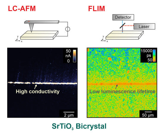
This study investigates the impact of extended defects such as dislocations on the electronic properties of SrTiO3 by using a 36.8° bicrystal as a model system. In order to evaluate the hypothesis that dislocations can serve as preferential reduction sites, which has been proposed in the literature on the basis of ab initio simulations, as well as on experiments employing local-conductivity atomic force microscopy (LC-AFM), detailed investigations of the bicrystal boundary are conducted. In addition to LC-AFM, fluorescence lifetime imaging microscopy (FLIM) is applied herein as a complementary method for mapping the local electronic properties on the microscale. Both techniques confirm that the electronic structure and electronic transport in dislocation-rich regions significantly differ from those of undistorted SrTiO3. Upon thermal reduction, a further confinement of conductivity to the bicrystal boundary region was found, indicating that extended defects can indeed be regarded as the origin of filament formation. This leads to the evolution of inhomogeneous properties of defective SrTiO3 on the nano- and microscales.

Graphical Abstract

1. Introduction

Strontium titanate (SrTiO3) is a prototype of a perovskite ternary oxide with mixed ionic-electronic conductivity [1]. It is of particular interest as an electrode material for solid oxide cells, which convert electrical energy to chemical energy and vice versa [2,3,4,5,6]. Such cells are seen as key elements for a future energy system based on renewable energy, to which an efficient energy storage concept is of the highest importance [7]. Furthermore, SrTiO3 holds promising potential as an electronic material for energy-efficient information technology utilising neuromorphic computing [8,9]. In general, the electronic properties of transition metal oxides such as SrTiO3 are complex, as they subtly depend on the stoichiometry of the material. When oxygen is removed from the solid oxide, positively charged oxygen vacancies are generated in the lattice, which are then compensated by electrons contributing to the material’s electronic conductivity [10]. Hence, controlled reduction can be applied to tune the conductivity. In recent years, it has been elaborated that extended defects such as dislocations can serve as preferential reduction sites as the formation energy of oxygen vacancies is locally significantly lowered due to lattice distortion [11,12]. This implies that the electronic properties are highly inhomogeneous in the first stage of reduction when a solid oxide such as SrTiO3 is reduced by either thermal annealing under low oxygen partial pressure or by applying an electric field, leading to stoichiometric polarization [13]. As the regions close to the dislocations are reduced at first, conducting paths evolve, which are called filaments [14]. Those filaments are of particular importance for resistive switching phenomena, as their resistance can be switched between a highly conducting ON and an insulating OFF state, which can be used for data storage [9,15]. Due to the small size of the reduced regions close to the dislocations, the inhomogeneities cannot be detected directly by macroscopic electrical measurements, and so analytical techniques with a sub-micrometre resolution must be employed. Previously, we have conducted detailed investigations of the SrTiO3 surface in different reduction states using local-conductivity atomic force microscopy (LC-AFM), where a metal-coated tip scans the surface in contact-mode while a voltage is applied and the current is measured [16]. These investigations have demonstrated that in the first stage of reduction, only a few, spatially highly confined conductive spots are detectable, which serves as a strong indicator of the presence of localized conducting paths [15]. To directly investigate the electronic properties of dislocation-rich grain boundaries, herein we investigate commercially available large-angle SrTiO3 bicrystals. In order to determine the electronic structure by optical means, we analyse the photoluminescence of the bicrystals in different reduction states. It has been shown that there is a close correlation between the presence of oxygen vacancies and luminescence [17,18,19]. In order to map the differences between the SrTiO3 matrix and bicrystal boundary, we employ FLIM, which has been shown to be a powerful tool for detecting small variations in the concentration of electronic charge carriers in SrTiO3 and has been employed to investigate inhomogeneities in Nb- and La-doped SrTiO3 [20,21]. It relies on the excitation of charge carriers by laser light and the registration of the resulting photoluminescence by a sensitive detector combined with the extraction of the fluorescence (hereinafter generally termed: photoluminescence) lifetime parameter by means of an ultra-precise determination of photon arrival [22]. This method provides a high spatial resolution (lateral: hundreds of nanometers; axial: a few micrometers), which allows the excitation of electrons specifically in the near-surface or deeper layers of the sample by adjusting the focus plane accordingly. In order to obtain information about the in-plane and out-of-plane distribution of the conductivity, we present LC-AFM maps of the polished surface above the grain boundary, as well as cross-sections of bicrystals, which were perpendicularly cleaved to the original surface. By combining the information from the two complementary techniques, FLIM and LC-AFM, we aim to address the electronic properties of the filamentary network forming along the dislocations.

2. Materials and Methods

SrTiO3 bicrystals in (100) orientation with a tilt angle of 36.8° and thickness of 0.5 mm produced by Verneuil growth (Crystec, Berlin, Germany and Shinkosha, Yokohama, Japan) were investigated. The crystals were epi-polished on both sides by the manufacturers. Nanoscale topography and conductivity were investigated using a high-vacuum atomic force microscope (JSPM, JEOL, Tokyo, Japan) equipped with Pt/Ir-coated tips (PPP-ContPt, Nanosensors, Neuchâtel, Switzerland). The samples were positioned on a heating stage, which allowed the performance of AFM measurements at 260 °C in situ. Thermal reduction of the crystals was conducted by annealing at 800 °C for one hour under vacuum conditions (p < 1 × 10⁻⁶ mbar) using a glass tube furnace for those samples investigated by electrical measurements. The reduced samples investigated by FLIM were annealed at 850 °C for 0.5 h under a 300 mbar deuterium atmosphere. Some crystals were etched using buffered hydrofluoric acid, resulting in the evolution of etch pits at the exits of the dislocations [23]. After etching, the samples were subsequently carefully rinsed with water in order to avoid contaminants on the surface influencing the electrical measurements. Macroscopic resistance measurements were conducted after the reduction in out-of-plane geometry using pasted indium electrodes with a diameter of 500 µm. The resistance was measured using a remote preamplifier (6430, Keithley, Solon, OH, USA). Simulations of the conductivity were performed using an electronic circuit simulator (Micro-Cap 6, Spectrum Software, Sunnyvale, CA, USA). FLIM measurements were performed on an upright scanning fluorescence microscope (A1R, Nikon, Amsterdam, The Netherlands) using a pulsed high repetition rate Ti:Sa-laser (λexc = 740 nm; 100 fs pulse width; 80 MHz repetition rate; MaTai HP DeepSee; Spectra Physics, Newport Cooperation, Santa Clara, CA, USA) for two-photon excitation. The time course of the photoluminescence intensity (decays) passing a broadband emission filter (410–650 nm) was detected by a GaAsP-hybrid photodetector (HPM-100-40, Becker & Hickl, Berlin, Germany) operating in single photon counting mode and reconstructed and analyzed for each pixel by time-correlated single photon counting electronics (Simple-Tau, Becker & Hickl) and software (SPCM64 and SPCImage 6.1, Becker & Hickl) [21,24,25]. Due to the high intensity of the laser light, multi-photon absorption by SrTiO3 was enabled to a significant degree and hence photoluminescence could be observed, although the single photon energy was smaller than the band gap of SrTiO3.

3. Results

3.1. Structure of the Bicrystal Boundary

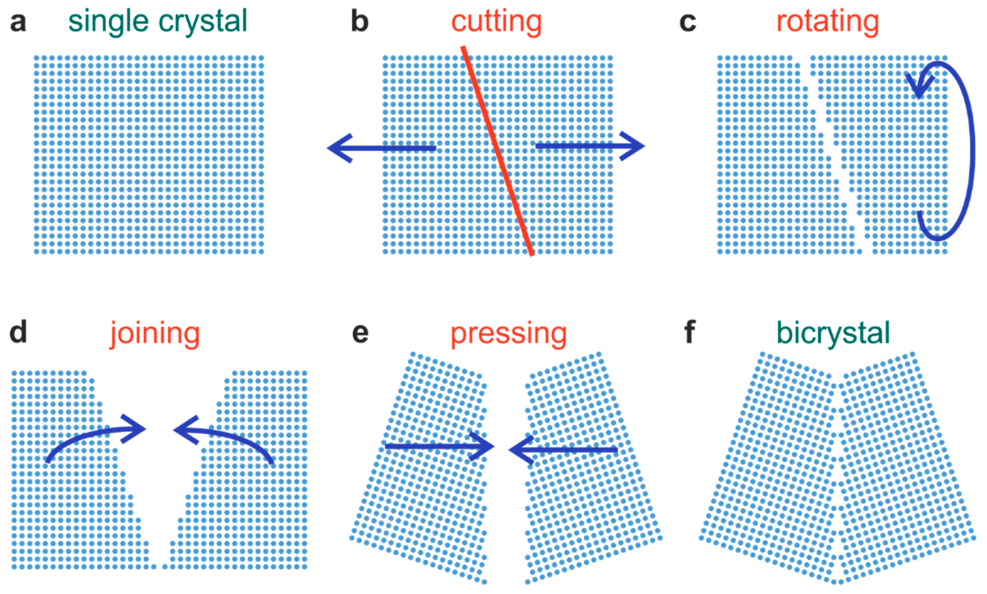
For this study, we selected bicrystals with a large tilt angle of 36.8°, providing a grain boundary with a high dislocation density. In order to produce such tilt bicrystals, a single crystal is cut at an angle of 18.4° with respect to the <100> axes. The two pieces are then joined together by pressing at high temperature [26,27,28]. In our study, this preparation was performed by the manufacturers. In the ideal case, this approach should result in an energetically favorable, symmetric Σ5 boundary that has a regular arrangement of dislocations although this is, however, difficult to achieve in reality [29,30]. Figure 1 displays the simplified scheme of constructing a Σ5 boundary for a cubic system. The detailed structure of the Σ5 boundary for SrTiO3 was theoretically calculated and also experimentally investigated by using high-resolution transmission electron microscopy (HR-TEM) [31,32].
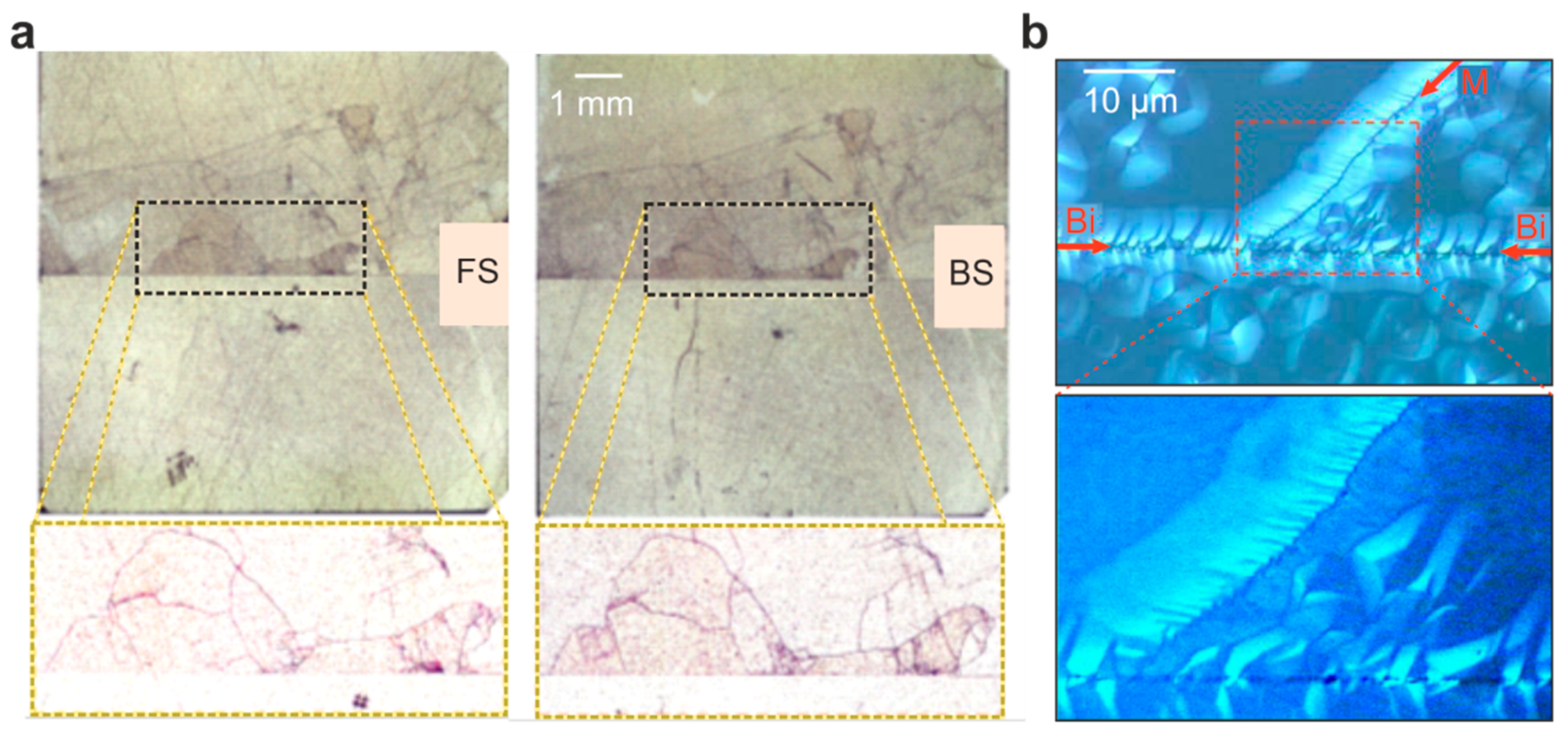
Before focusing on the investigation of the electrical and optical properties of the SrTiO3 bicrystals, we would like to comment on the quality of commercially available bicrystals. As elaborated in detail in our previous review [14], a well-ordered arrangement of dislocations at the Σ5 boundary is not always observed. Using the etch-pit technique to mark the exits of dislocations, it has been noted that commercially available SrTiO3 bicrystals are far from perfect [14]. An example is shown in Figure 2a. After short etching of the crystal using HF, one can observe that there is not only one line of dislocations at the bicrystal boundary, but a mosaic structure of many small grains emerging from the junction can also be identified, each grain itself possessing dislocation-rich grain boundaries. As both the front- and backside of the bicrystal show a comparable pattern of etch pits.
We can conclude that the corresponding dislocations are not only near-surface dislocations but run through the entire crystal, thus marking real grain boundaries. Furthermore, it can also be observed that the dislocation density of the upper part of the bicrystal is much higher than in the lower part. This could relate to the fact that the two parts of the original crystal, which were joint after rotating and polishing (Figure 1), had slightly different properties. Taking a closer look at the structure of the boundary (Figure 2b), one can at first detect a high degree of irregularities at the bicrystal boundary (marked “Bi” in Figure 2b), indicating that the arrangement of dislocations is not as regular as would be theoretically expected. In contrast to this, the distribution of additional etch pits that were found at grain boundaries, forming a mosaic structure (marked by “M” in Figure 2b), appears to be much more regular. As we have observed such inhomogeneous dislocation arrangements in a variety of Verneuil-grown bicrystals purchased from different suppliers, we can conclude that dislocations have a strong tendency towards clustering and bundling. Hence, care should be taken when comparing results obtained from such bicrystals with theoretical predictions. To emphasize that the investigated bicrystals do not exhibit a well-defined Σ5 boundary but rather a broad, inhomogeneous, macroscopic dislocation network around the junction, we refer to them as “real” bicrystals. However, although the boundary structure of the investigated bicrystals was not ideal, we were still able to use them as model systems for the investigation of the impact of dislocations on the properties of SrTiO3. Due to the presence of a mosaic structure generating a complex network of dislocations, the structure of the bicrystal was even closer to practical applications than originally intended, e.g., solid oxide fuel cells with a variety of different types of grain boundary [33].

3.2. Investigation of Local Conductivity

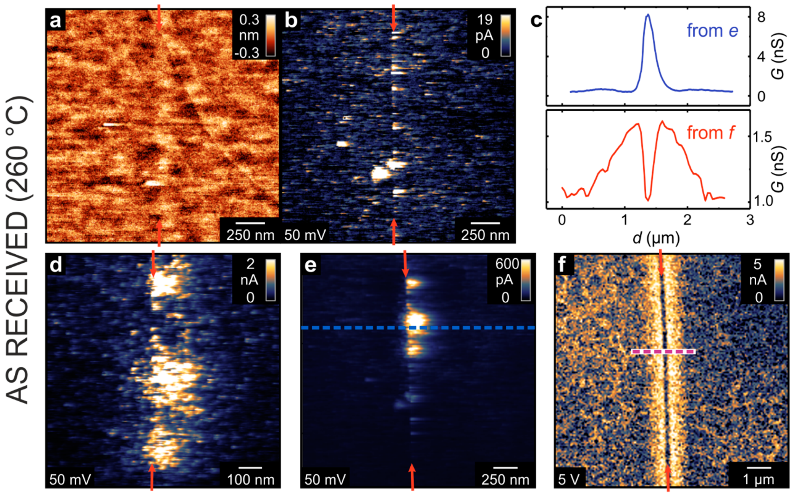
Using LC-AFM, the electrical properties of the as-received bicrystal junctions were investigated as presented in Figure 3. In order to increase the conductivity of the solid oxide by means of thermal activation, the measurements were performed at a temperature of 260 °C under vacuum conditions. As the bicrystals had been epi-polished by the manufacturer, the surface in the vicinity of the junction was atomically flat. Hence, the position of the boundary is hard to identify in the AFM topography map (Figure 3a). However, in the corresponding current map, recorded simultaneously with the topography by means of a voltage of 50 mV (Figure 3b), an irregular arrangement of conducting spots along the junction is present. Well-conducting spots cannot only be seen directly at the junction but also several 100 nm away from the junction. In other regions along the boundary, spots with even higher conductivities have been recorded (Figure 3e). Zooming in on the well-conducting spots (Figure 3d), it can be seen that they consist of smaller spots with diameters in the range of 10–100nm. This could indicate that there is an agglomeration and bundling of conducting filaments formed along of the dislocation network. In some parts of the bicrystal junction, however, the picture was found to be completely different. The map shown in Figure 3f was recorded in a region that did not show any detectable current at a voltage of 50 mV. However, after increasing the voltage to 5 V, a current in the nA range was observed. Directly at the boundary, the current was relatively low, whereas next to the boundary was a broad zone of 500 nm-width with a higher current. Figure 3c shows a comparison of line profiles obtained from the current maps in Figure 3e,f that illustrate the opposing behavior. Whereas, in the latter case, the boundary appears to have an increased but inhomogeneous conductivity, in the other case, the boundary itself appears to be insulating but with a zone of increased conductivity formed beside it. This illustrates that in a “real” bicrystal, a variety of electrically conducting paths can be present, which most likely relate to the imperfections in bicrystal fabrication, as described above.
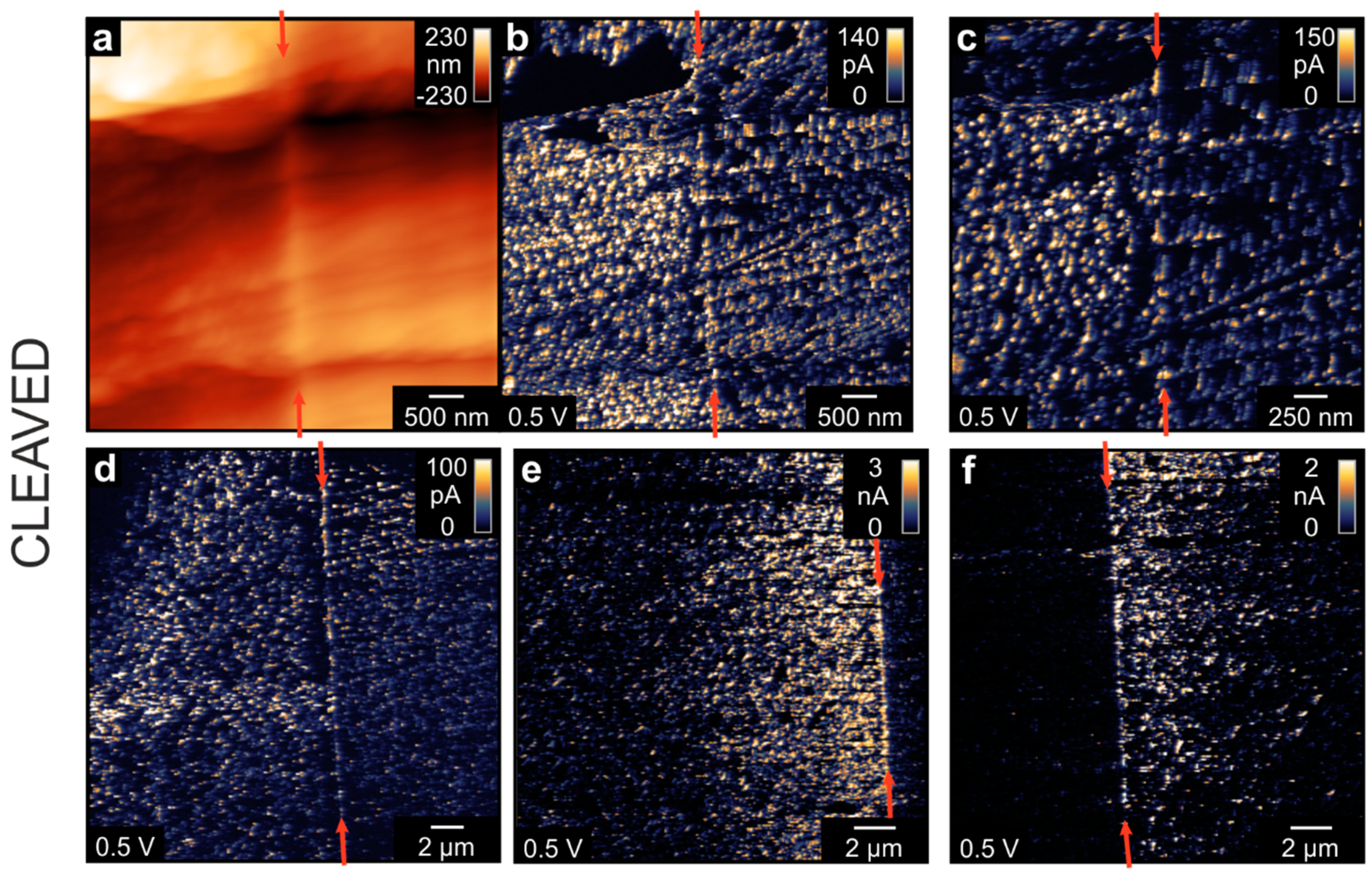
In order to obtain an insight into the conductivity in all dimensions, we investigated the bicrystal after cleaving it perpendicular to the boundary. As SrTiO3 crystallizes in the cubic perovskite structure, it does not possess a defined cleavage plane, resulting in a shell-like fracturing [34]. Hence, the topography map of the cleaved face (Figure 4a) is relatively rough and different facets can be observed. The corresponding current maps at the same position (Figure 4b,c) show an irregular spot-like conductivity pattern typical for cleaved SrTiO3. Although the bicrystal boundary can be readily observed as a line of conducting spots in the center of the image, the current level of these boundary spots was the same as that of spots several 100 nm away from the boundary. This again indicates that a complex filamentary network in the junction zone had evolved. Comparing the topography image with the current map, it can be observed that the distribution of current spots follows the edges and kinks of the facets that had evolved during the cleaving procedure. This could also be an indication for the correlation between dislocations, which tend to agglomerate around edges and conducting filaments. In other parts of the cleavage plane, the distribution of conducting spots showed remarkable differences. In some positions, a relatively uniform distribution of spots on both sides of the boundary could be observed (Figure 4d). Nevertheless, in other positions, there was a distinct difference between the two parts of the bicrystal. In Figure 4e,f, one side of the bicrystal had a significantly lower conductivity than the other part with the boundary being a sharp separation line between the two regions. This could again be related to the fabrication process, whereby two parts of the original SrTiO3 crystal, which might have had a slightly different content of point defects or extended defects, had been joined together to form the bicrystal.
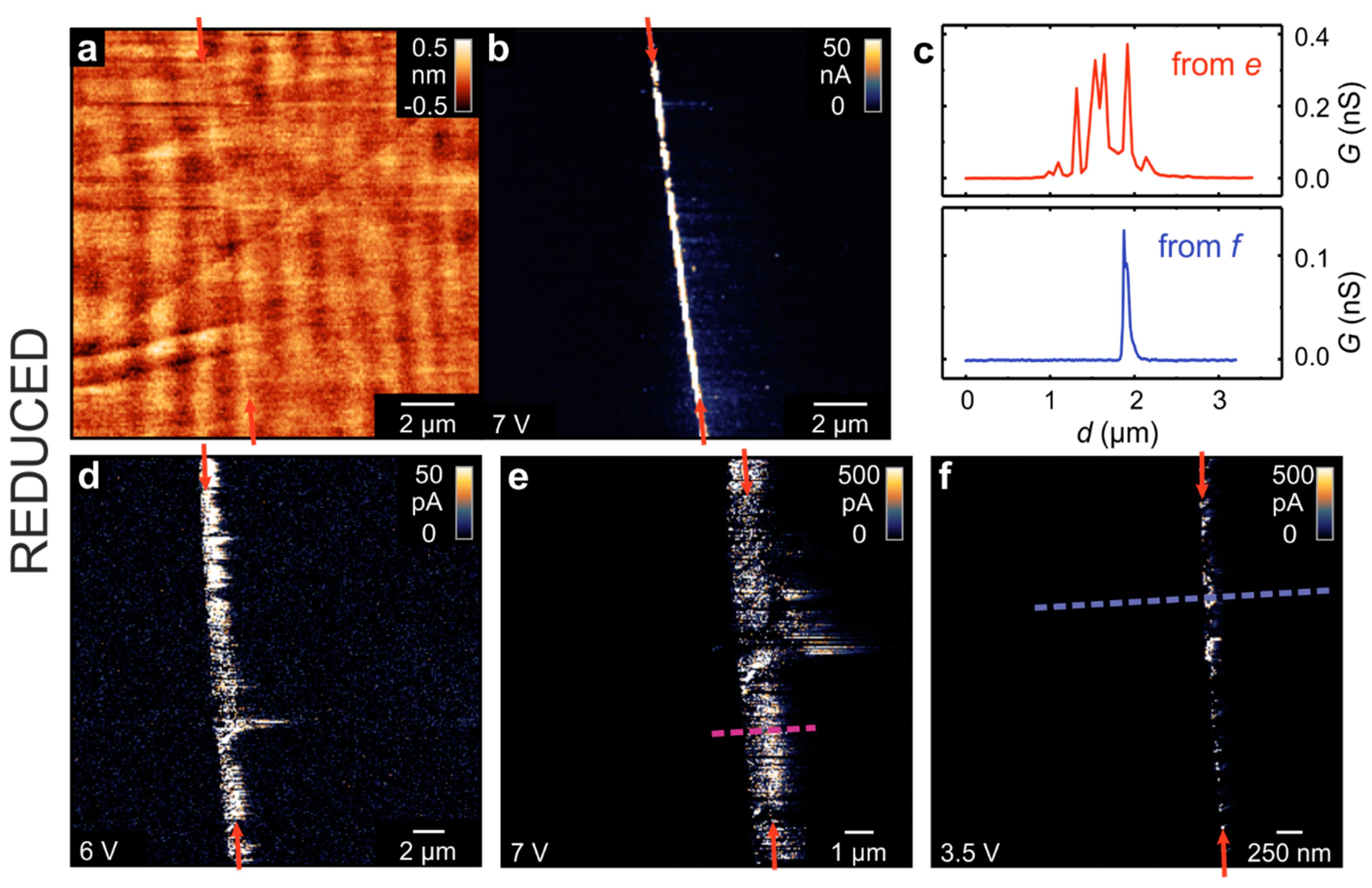
The impact of the thermally induced reduction on the local electrical properties of the bicrystal was investigated by repeating the LC-AFM experiment of the polished surface after annealing the sample in a vacuum in order to generate oxygen vacancies and charge carriers. The results are presented in Figure 5. In the topography map, it can be seen that the surface of the crystal remained flat and no holes or islands are observed. In the conductivity maps, which were obtained at room temperature, the bicrystal junction can be easily identified as a line with increased conductivity. This general behavior has been observed for all of the investigated spots along the junction, but differences in the distribution of conducting spots on the nanoscale have also been found. In some regions, conducting spots could only be found directly at the boundary but with an irregular distribution along it (Figure 5f). In other regions, a broad band of conducing spots can be observed to follow the boundary line (Figure 5d,e). By extracting line profiles perpendicular to the boundary, these differences are illustrated (Figure 5c). In the first case, the width of the well-conducting area at the boundary was in the range of 100 nm, while in the second, the inhomogeneously conducting band had a width of more than 1 µm. This difference might again relate to the imperfections in bicrystal production; however, the main result from this measurement is that the region of increased con-ductivity is much more confined to the boundary after thermal reduction than prior (Figure 3). It must be noted that the measurements shown in Figure 5 were performed ex situ after the exposure of the sample to ambient conditions. It has been shown previously that the thermally reduced SrTiO3 surface is highly conductive under in situ conditions [18] but that the majority of the surface becomes passivated upon exposure to oxygen at room temperature, thus becoming insulating again [16]. Only a few conducting spots were found to remain highly conductive. Hence, we can conclude that in the measurements shown in Figure 5, the remaining conductive filaments were preferentially formed in the dislocation-rich zone upon reduction. A similar correlation between the dislocations and the formation of conducting paths resistant to re-oxidation has been found in TiO2 [35].

3.3. Investigation of Macroscopic Conductivity

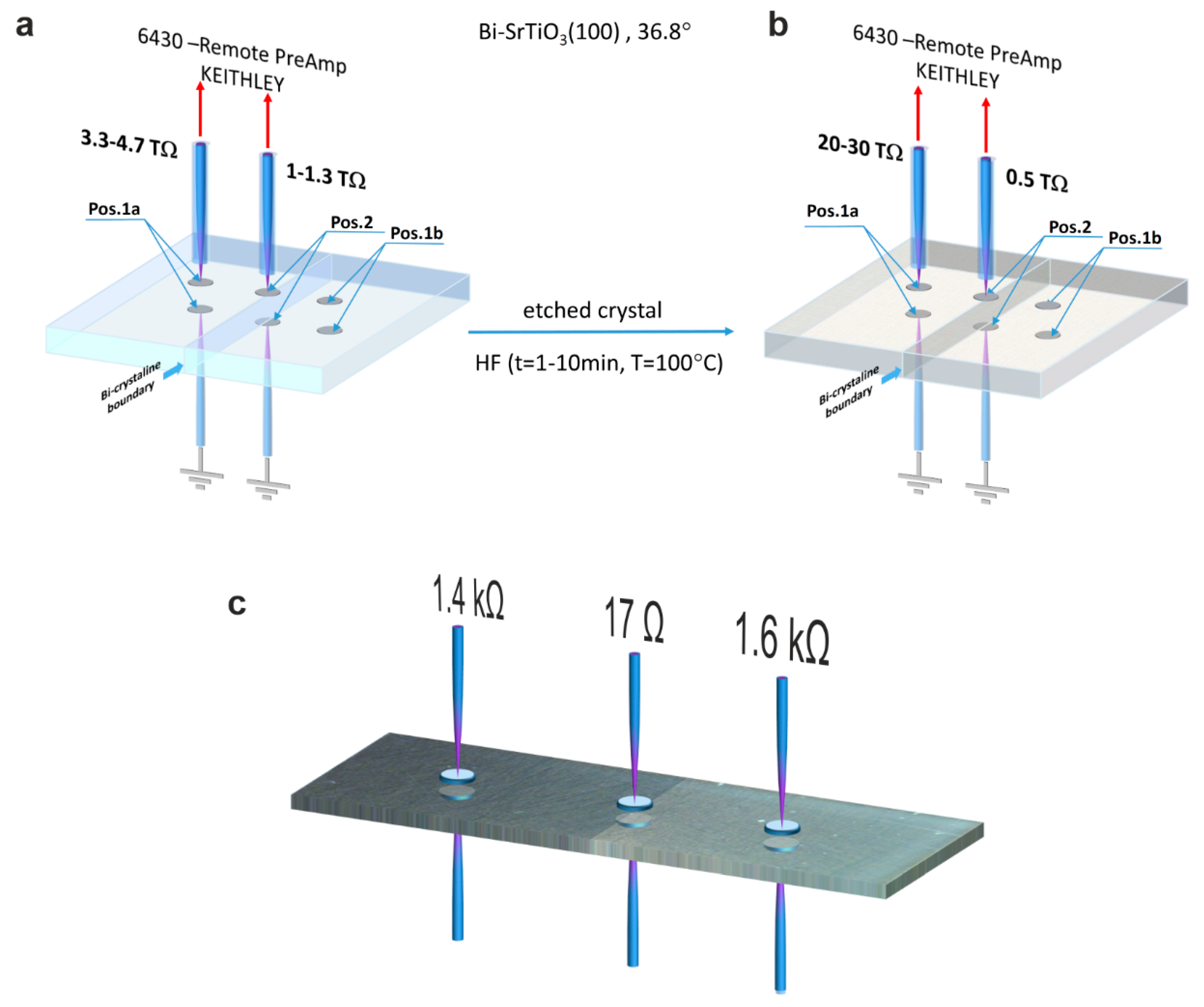
In order to illustrate the significance of the bicrystal boundary on even macroscopic electronic transport, resistance measurements in the out-of-plane geometry were performed, as illustrated in Figure 6. In order to create good electrical contact with the crystal, In electrodes were used. The measurements were conducted at room temperature using direct current (DC) voltages below 1 V. The electrical resistance of the crystal was in the TΩ range, which requires the use of a highly sensitive and sufficiently screened measurement setup. The resistance measured at two positions away from the boundary (position 1a,b) was higher by a factor of 3–4 than that measured exactly at the boundary (position 2), which proves that the enhanced conductivity at the dislocation-rich boundary also has consequences at the macroscale. In a second step, we removed the surface layer by means of HF etching and repeated the measurement of the resistance after depositing fresh In electrodes. Now, the resistance measured away from the boundary was higher than before, while the resistance measured at the boundary was slightly lower (Figure 6b). In the same way, we investigated another bicrystal, which was thermally reduced (Figure 6c). In comparison to the as-received crystal, the resistance had dropped by many orders of magnitude into the kΩ range. A resistance of 17 Ω was measured directly at the boundary, which is lower by a factor of more than 80 compared to the surrounding. This further supports the conclusion that dislocations serve as easy reduction sites, thus providing a template for the formation of highly conducting filaments within the poorly conductive bulk.
When trying to understand the electric conductivity of SrTiO3, the impact of dislocations must be taken into account, not only at the boundary itself but also in the surface layer of the polished crystal. We have described this effect in detail in Szot et al. [9,13,14], but we will briefly recall the main conclusions here, as they will be useful for the analysis of the photoluminescence in the last section of this paper. The crystal preparation by the manufacturers includes cutting and polishing of the crystals. This induces a high density of dislocations, whose density decreases from the surface towards the bulk as shown in Figure 7a. This graph shows the dislocation density in the surface layer measured by TEM analysis [36]. It can be seen that the density decreases significantly towards the bulk, where densities below 108/cm2 are typically found for Verneuil-grown SrTiO3 crystals [23,37]. Additionally, the density of the conducting filaments of the reduced SrTiO3 surface as a function of the depth, which was obtained via the LC-AFM analysis of a cleaved sample, is shown [14]. It can be seen that the density of dislocations measured by TEM and the density of the conducting filaments both follow the same trend. This indicates that the filaments were formed along the dislocations. According to TEM analysis, one can distinguish two types of dislocations. Type “A” has a core consisting of αSrO + βTiO2 + γTi2O3, which causes flexoelectric polarization, while type “B” has a structure of βTiO2 + γTi2O3 + δTiO, causing ferroelectric polarization [38,39,40].
We built a layered structure, wherein each layer represents a region of constant filament (dislocation) density m. In the model of the hierarchical tree, the filament density gets reduced by a factor of two between subsequent layers.
m n + 1 = 1 2   m n
Using this formula, we estimated the thickness l of each layer from the measured depth-dependence of the filament density in Figure 7a.
l n + 1 = d ( m n + 1 ) d ( m n )
To transform this model with varying layer thicknesses into a quadratic grid of resistors, we scaled the single resistor elements accordingly.
R n + 1 = m n m n + 1 · l n + 1 l n · R n = 2 · l n + 1 l n · R n
As the starting value of the resistor elements at the surface, we chose R1 = 1 TΩ, which was derived from LC-AFM data [9]. Thereby, we constructed five layers of different resistors that were connected as a regular network, as shown in Figure 8a. In the center of the simulation grid, we modelled the bicrystal boundary as a slab of low-resistance layer having the same configurations as those on the surface. In order to simulate the electrical measurements shown in Figure 6, we modelled the connection to the voltage source either at the sides of the regular grid (position 1a) or directly above the bicrystal boundary (position 2). The results of this simulation for the as-received crystal are shown in Figure 8b. The graphic illustrates the situation after back transformation into the configuration of the hierarchic tree with varying layer thickness. It can be seen that the majority of the current flows along the surface layers and along the bicrystal boundary reproducing the behavior observed by LC-AFM. The simulated total resistance present between the electrodes was 11.5 TΩ, which is on the same order of magnitude as the measured resistance, showing that the setup of the simulation was reasonable. When moving the electrode above the bicrystal boundary, the simulation results in a significantly lower total resistance of 3.8 TΩ, thus also reproducing the experiment.
For the simulation of the etched crystal, we removed the topmost layer of resistors, whose thickness corresponds to 1–2 µm. This was justified because we had previously determined the etching rate using an AFM analysis of the etch pits [14]. The rest of the simulation grid remained the same as for the simulation of the as-received crystal. The results in Figure 8c show that the total resistance was increased to 23.1 TΩ in the undistorted region, while the resistance for the electrode configuration directly above the bicrystal boundary was 3.84 TΩ and almost the same as for the as-received crystal.
In summary, the electrical circuit simulation shows that the model of a three-dimensional network of dislocations in the shape of a hierarchical tree is plausible and can qualitatively explain the observed conductivity behavior. A graphical illustration of our model is shown in Figure 9. Already in the as-received crystal (center panel), the network of filaments has a higher conductivity than the surrounding SrTiO3 matrix and results in an overall semiconducting behavior. Upon etching (left panel), the surface layer is removed resulting in a lower conductivity, as fewer filaments for transport in the surface layer are available. Additionally, an incorporation of fluorine from hydrofluoric acid into the crystal occurs [41]. During thermal reduction under vacuum conditions (right panel), oxygen is removed from the crystal, typically in the range of 1014–1017O ions/cm3, depending on the conditions (oxygen partial pressure, temperature, time) [14]. Due to the preferential reduction limited to the core of the dislocations, these are transformed into metallic filaments [16]. The local concentration of the oxygen vacancies close to the dislocations is 1020–1021/cm3 and the Mott criterion is locally fulfilled [42,43]. This mechanism is further supported by a rearrangement and bundling of dislocations occurring due to the high-temperature annealing [14]. In consequence, this implies that the formation of conducting filaments can be influenced by the introduction of dislocations e.g., by forming a bicrystal boundary or by mechanical polishing of the surface. This could offer promising opportunities to tune the electrical properties of SrTiO3 by mechanical methods.

3.4. Investigation of Photoluminescence

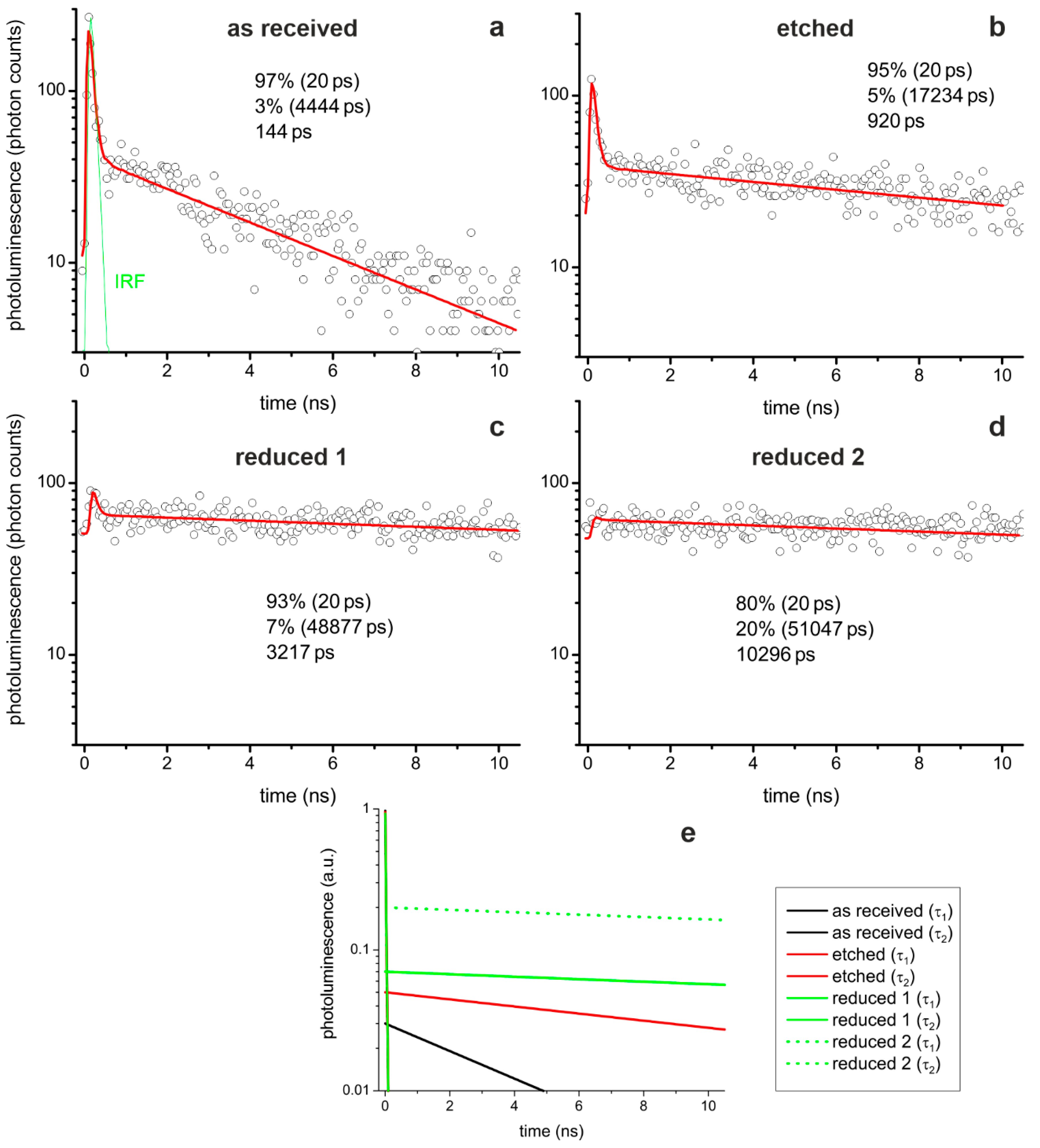
As a complementary method for gaining insight into the electronic properties of the boundary region, FLIM was employed. To generate lifetime maps, the pulsed laser was scanned over the surface while at each point, a photoluminescence decay trace was recorded. Before showing the maps, we briefly discuss the lifetime calculation by fitting the decay traces to exponential functions. We investigated SrTiO3 bicrystals following different preparation steps, as is shown in Figure 10. Starting from an as-received crystal, we etched the crystal with HF analogously to the electrical measurements. This process simultaneously led to the evolution of etch pits marking the dislocations, as we will later show. Finally, we conducted thermal reduction, which resulted in sufficient self-doping to transform the crystal into the metallic state [14].
The photoluminescence traces for all three sample conditions are best described by a fitting model consisting of two exponential decays using a fast (≤20 ps) and a slow (>1 ns) photoluminescence process. The lifetime of the fast fit component was fixed at 20 ps. It is presumably even shorter, as the fast decay component and descending flank of the instrument response function (IRF) overlap. As we used dedicated dichroic filters, no scattered light reached the detector and we can conclude that the fast component is a real decay component. This indicates that at least two different decay channels exist in the investigated SrTiO3 samples.
A similar conclusion has been derived by Rubano et al. from single-photon excitation photoluminescence experiments, who ascribed a fast decay channel to the direct recombination of free electron–hole pairs and a slow decay channel to the recombination of bound electron–hole pair [44,45,46]. These bound electron–hole pairs could be correlated with longer-lived deep trap states within the bandgap of SrTiO3, as was already suggested in the case of hydrogenated TiO2 [47]. Presumably, these states originate from intrinsic defects, such as oxygen vacancies [48]. Recently, Crespillo et al. [49] conducted an in-depth study of the recombination mechanisms in SrTiO3 and attributed the blue emission at 2.8 eV to a transition from conduction band states to the ground state level of the self-trapped exciton center, while the spontaneous annihilation of a self-trapped exciton center resulted in a green emission at 2.5 eV. However, one must also take into account that the presence of dislocations in the surface layer has an impact on the local electronic structure. It should be considered that vacancies might remain isolated only below a certain concentration. With increasing vacancy concentration, also the defect–defect interactions play a more important role, which could lead to agglomeration and clustering of vacancies, preferentially at dislocations. Hence, the models presented in the literature, which were developed for ideal crystals with statistical distributions of point defects, must be extended.
Comparing the three reduction states (Figure 10a–d), it can be seen that the lifetime of the slow component increases with reduction. After etching, the lifetime of the slow component increased by a factor of four and, after thermal reduction, even by a factor of ten. This also led to an increase in the average lifetime, which was calculated as the amplitude-weighted mean of the two lifetimes. With regard to the two exemplarily shown decay traces of the thermally reduced crystal, it can be seen that the fit of the fast component becomes difficult. In some pixel photoluminescence decays, the fast component can clearly be identified (Figure 10c) but is barely visible in others (Figure 10d). Hence, the average lifetime is much shorter in the first case due to the large amplitude of the fast component than in the latter case, which results in a larger variation in the lifetime maps of the reduced crystal compared to the other two conditions (cf. Figure 11 and Figure 12).
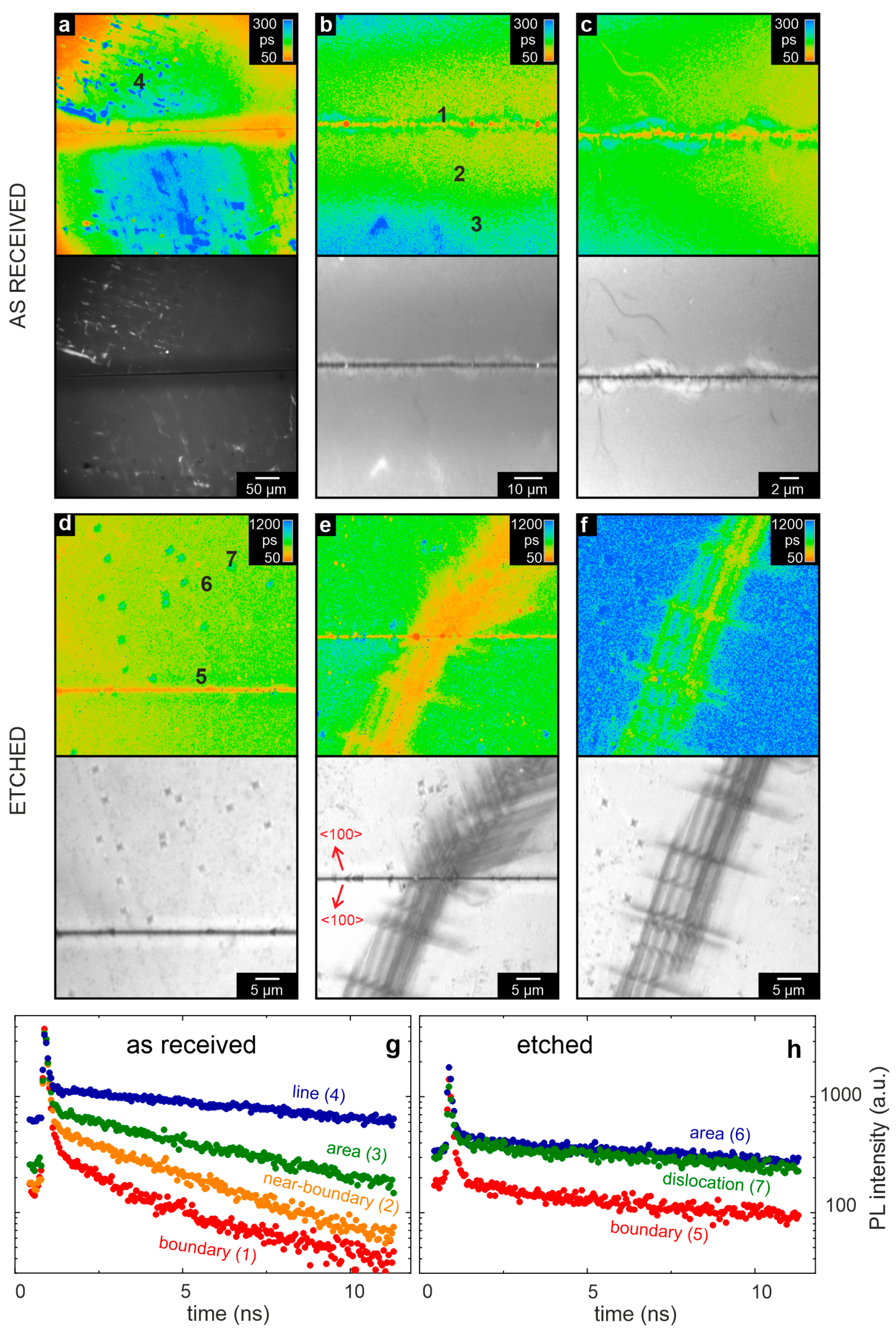
In the following, we focus on an investigation of the photoluminescent properties of the bicrystal, as observed initially in the as-received state. From each measurement region, the photoluminescence lifetime and intensity maps are depicted in Figure 11a–c, together with the decay traces of selected spots in Figure 11g. In the photoluminescence maps, the bicrystal junction can clearly be identified as a narrow, straight region of lower photoluminescence intensity. Along the boundary, an arrangement of spots can be observed that has a shorter lifetime than the surrounding. Those spots were occasionally embedded in structures with a meander-like shape and longer lifetime. An explanation for these observations could be that the mobility of the charge carriers along the dislocations is enhanced. Hence, the excited carriers can be effectively transported to recombination centers, resulting in shorter exciton lifetimes.
Additionally, further from the junction, inhomogeneous features with even longer lifetimes can be observed. Comparing the intensity and lifetime maps, the same structures can be detected around the boundary region. A shorter lifetime corresponds to a lower intensity and vice versa.
Furthermore, it must be considered that the crystallographic structure of dislocations can significantly alter from that of the matrix, as discussed above. In consequence, the electronic structure of dislocations differs from that of SrTiO3, mainly in relation to a surplus of the Ti3+ valence state providing different decay mechanisms, e.g., it might be possible that radiation-free Auger recombination becomes more important at the boundary, decreasing the intensity and lifetime. Additionally, the dislocations are surrounded by a stress field that leads to local flexoelectricity, which is known to have an impact on the luminescence properties [38,39,50].
In order to more directly investigate a potential correlation between the position of the dislocations and photoluminescence lifetime, the bicrystal boundary was investigated by FLIM after etching the surface of the bicrystal by means of HF. As the etching process preferentially starts at the dislocation points, this method allows the position of the dislocations to be marked by the etch pits (Figure 2). The photoluminescence and intensity maps shown in Figure 11d–f at different positions on the bicrystal clearly depict the position of the etch pits. In comparison to the measurement of the as-received bicrystal, the average lifetime of the etched bicrystal is significantly higher. A possible reason for this finding could lay in the removal of the upper surface layer of the polished bicrystals upon etching. As discussed above, the dislocation density of the surface layer is much higher than that of the bulk [36]. Hence, this could indicate that the presence of dislocation correlates to a smaller luminescence lifetime, which would be in agreement with the conclusions derived from the lifetime analysis of the boundary. Furthermore, secondary effects such as a modification of the chemical composition of the surface layer by fluorine, leading to the evolution of SrTiFxOy, may contribute [41]. Despite these uncertainties, the position of the etch pits can be identified in the photoluminescence maps. As expected, a high concentration of etch pits can be observed close to the boundary. Although the average lifetime is longer compared to the as-received bicrystal, the relative differences between the boundary and the rest of the surface were preserved. At the boundary itself, the lifetime was shorter and the intensity lower than in the surrounding area. Additionally, a regular arrangement of stripes with enhanced etch pit density aligned along the main crystal axes can be observed (Figure 11e,f). This dislocation-rich zone spreads from the bicrystal boundary in both parts of the bicrystal, indicating that the presence of mechanical stress leads to the generation and ordering of dislocations. The same holds true for the zone of arranged dislocations, indicating that this network of dislocations had similar properties as the bicrystal boundary. On the contrary, isolated etch pits separated from the boundary can be identified, which also show a lower photoluminescence intensity but an increased photoluminescence lifetime (see detailed analysis in the Supplementary Materials). In order to explain the differences between the isolated and bundled dislocations, in our opinion, two scenarios must be considered. It is known that i) in SrTiO3, different types of dislocations are present [51]. Hence, it is conceivable that the details of structure and chemical composition of the core of the dislocations differ between isolated dislocations and dislocations forming boundaries. An alternative explanation would be ii) that the isolated dislocations serve as electron traps, thus resulting in longer photoluminescence lifetimes. In contrast, a dislocation network would provide a variety of conducting paths, thus allowing for the easy transport of the exited electron to a lattice site where efficient relaxation into the ground state is possible, resulting in shorter photoluminescence decay times. Such an effect would also be in accordance with the conclusions derived from our LC-AFM and macroscopic resistance investigations, which show that the electronic conductivity along a network of dislocations is significantly enhanced. A similar phenomenon has been observed by Wang et al. using cathodoluminescence [52]. They found a higher luminescence at naturally occurring dislocations whereas on slip lines, which were induced by mechanical scratching, a lower luminescence was recorded.
Finally, we investigated the effect of thermally induced reduction on the photoluminescence properties of the bicrystal. After heating the bicrystal under reducing conditions at 850 °C for one hour, the measurements were conducted at room temperature in accordance with the procedure of the LC-AFM investigations in Figure 5. In the photoluminescence maps shown in Figure 12a, the position of the boundary can still be clearly identified as having a lower intensity and lifetime than the surrounding surface. This follows the same trend as prior to the reduction (Figure 11). The photoluminescence average lifetime at the bicrystal boundary but even more so the lifetime measured apart from the boundary had changed significantly (see the very different photoluminescence lifetime scales in Figure 11 and Figure 12) and became slower and more inhomogeneous. In some regions on the sub-micrometer scale, the lifetime had increased by a factor of 100, whereas in other regions, it was almost the same or even slightly lower compared to the as-received sample. This effect is strongly influenced by variations in the presence of the fast decay component, as discussed above. The observed inhomogeneities could relate to local variations in the generation of oxygen vacancies and a change in the Ti/Sr ratio leading to variations in the electronic structure and thus to the dominant decay channel. For instance, oxygen vacancies can serve as localized traps for electrons, contributing to the observed extension of photoluminescence lifetimes [48]. This effect could also be related to self-trapping of polarons, e.g., at the Ti site next to an isolated oxygen vacancy, which was found to have a significant impact on the electronic structure and the luminescence [53]. Nevertheless, in our data, not only the magnitude of the fast decay component but also the lifetime of the slow decay component has changed dramatically, being about 10 times longer compared to the as-received SrTiO3 crystal.
It is also known that with the thermally induced reduction of SrTiO3, the surface region becomes Ti-rich and eventually, titanium suboxides form [54,55]. Hence, the incipient phase transformation could lead to clustering effects on the nanoscale, resulting in the observed inhomogeneous photoluminescence lifetime distribution. Regarding the decay curves shown for two selected spots at the boundary and surrounding surface (Figure 12b), it can be seen that the fast component at the boundary had a much higher amplitude than in the surrounding surface. In consequence, the amplitude-weighted average lifetime at the boundary was also much shorter than in the surrounding surface.
Summing up the time-resolved photoluminescence investigation, we can state that in all measurements, two decay channels can be observed. The slow component appears to relate to the SrTiO3 matrix and depends strongly on the crystal preparation. It is significantly suppressed close to the bicrystal boundary and dislocation-rich slip bands, where the short component is dominant. One potential explanation for this behavior could be that the network of filaments formed along the dislocations provides an easy migration path for charge carriers. Hence, generated electron–hole pairs can easily be transported to recombination centers located at the dislocations. Our results show that the detailed physical nature of the photoluminescence decay close to dislocations is complex, as one has to consider the electronic structure of SrTiO3, the electronic structure of the dislocations, and furthermore potential easy migration paths of the excited charge carriers.
4. Conclusions

The investigation of the 36.8° bicrystal boundary of SrTiO3 by using the complementary techniques LC-AFM, resistance analysis and FLIM revealed a significant impact of the presence of dislocation-rich areas on the electronic properties. Initially, it became obvious that the distribution of dislocations in commercially available bicrystals can show distinct deviations from the expectation of having an ideal symmetrical grain boundary. Hence, this effect should always be taken into account when interpreting results obtained using bicrystals as model systems. In spite of this difficulty, due to the availability of only non-ideal samples, the electrical conductivity in the boundary region was found to be locally increased in relation to inhomogeneously distributed well-conducting spots, indicating the presence of filamentary conductance paths. After a thermally induced reduction in a vacuum, this effect became even more pronounced and a confinement of the conductive areas close to the boundary was detected. By mapping the photoluminescent properties, the special role of the dislocation-rich boundary was also confirmed, having lower intensity and a shorter lifetime than the undistorted region of the crystal. These results can be interpreted in agreement with the hypothesis that dislocations in SrTiO3 serve as preferential reduction sites, thus being the seed for the formation of filamentary conductance paths that form inside an insulating matrix. As the photoluminescence properties are also affected by the presence of dislocations, we can further conclude that the local electronic structure along a network of dislocations deviates from ideal SrTiO3. This may indicate that the crystallographic structure close to the extended defects has been altered and hence SrTiO3, with dislocations, must be regarded as a structurally and stoichiometrically inhomogeneous system on the nanoscale. With respect to practical applications, the relationship between dislocations and locally increased conductivity could help illuminate degradation effects in solid oxide electrolysis cells, where mixed ionic-electronic-conducting oxides are employed as electrode materials in the form of ceramics and typically have a large amount of dislocations at the grain boundaries.

Supplementary Materials

The following are available online at https://www.mdpi.com/2073-4352/10/8/665/s1, Figure S1: Detailed analysis of the photoluminescence lifetime and intensity measurement on the HF-etched SrTiO3 surface. The arrows mark the position of selected local minima (orange) and local maxima (blue) of the lifetime. Profiles of lifetime and intensity are plotted for the dashed-lines.

Author Contributions

Conceptualization, C.R. and K.S.; investigation, formal analysis, and visualization, C.R., D.W., T.G., and K.S.; writing—original draft preparation, C.R.; validation and writing—review and editing, C.R., D.W., T.G., F.K., C.K. and K.S.; supervision, F.K., C.K., and K.S. All authors have read and agreed to the published version of the manuscript.

Funding

F.K. acknowledges the support of the Polish National Science Center (UMO-2018/29/B/ST5/01406).

Acknowledgments

We gratefully acknowledge C. Wood for proofreading the manuscript.

Conflicts of Interest

The authors declare no conflict of interest.

References

  1. Noll, F. SrTiO3 as a prototype of a mixed conductor—Conductivities, oxygen diffusion and boundary effects. Solid State Ion. 1996, 86–88, 711–717. [Google Scholar] [CrossRef]
  2. Escudero, M.J.; Irvine, J.T.S.; Daza, L. Development of anode material based on La-substituted SrTiO3 perovskites doped with manganese and/or gallium for SOFC. J. Power Sources 2009, 192, 43–50. [Google Scholar] [CrossRef]
  3. Alvarado Flores, J.J.; Ávalos Rodríguez, M.L.; Andrade Espinosa, G.; Alcaraz Vera, J.V. Advances in the development of titanates for anodes in SOFC. Int. J. Hydrogen Energy 2019, 44, 12529–12542. [Google Scholar] [CrossRef]
  4. Mahato, N.; Banerjee, A.; Gupta, A.; Omar, S.; Balani, K. Progress in material selection for solid oxide fuel cell technology: A review. Prog. Mater. Sci. 2015, 72, 141–337. [Google Scholar] [CrossRef]
  5. Shen, X.; Sasaki, K. Robust SOFC anode materials with La-doped SrTiO3 backbone structure. Int. J. Hydrogen Energy 2016, 41, 17044–17052. [Google Scholar] [CrossRef] [Green Version]
  6. Li, R.; Zhang, C.; Liu, J.; Zhou, J.; Xu, L. A review on the electrical properties of doped SrTiO3 as anode materials for solid oxide fuel cells. Mater. Res. Express 2019, 6, 102006. [Google Scholar] [CrossRef]
  7. Hansen, J.B. Solid oxide electrolysis—A key enabling technology for sustainable energy scenarios. Faraday Discuss. 2015, 182, 9–48. [Google Scholar] [CrossRef] [PubMed]
  8. Yin, X.-B.; Yang, R.; Xue, K.-H.; Tan, Z.-H.; Zhang, X.-D.; Miao, X.-S.; Guo, X. Mimicking the brain functions of learning, forgetting and explicit/implicit memories with SrTiO3-based memristive devices. Phys. Chem. Chem. Phys. 2016, 18, 31796–31802. [Google Scholar] [CrossRef] [PubMed]
  9. Szot, K.; Bihlmayer, G.; Speier, W. Nature of the Resistive Switching Phenomena in TiO2 and SrTiO3. In Solid State Physics 65; Camley, R.E., Stamps, R.L., Eds.; Academic Press: Cambridge, MA, USA, 2014; pp. 353–559. [Google Scholar]
  10. Denk, I.; Münch, W.; Maier, J. Partial Conductivities in SrTiO3: Bulk Polarization Experiments, Oxygen Concentration Cell Measurements, and Defect-Chemical Modeling. J. Am. Ceram. Soc. 1995, 78, 3265–3272. [Google Scholar] [CrossRef]
  11. Marrocchelli, D.; Sun, L.; Yildiz, B. Dislocations in SrTiO3: Easy To Reduce but Not so Fast for Oxygen Transport. J. Am. Chem. Soc. 2015, 137, 4735–4748. [Google Scholar] [CrossRef]
  12. Waldow, S.P.; De Souza, R.A. Computational Study of Oxygen Diffusion along a[100] Dislocations in the Perovskite Oxide SrTiO3. ACS Appl. Mater. Interfaces 2016, 8, 12246–12256. [Google Scholar] [CrossRef]
  13. Szot, K.; Speier, W.; Carius, R.; Zastrow, U.; Beyer, W. Localized Metallic Conductivity and Self-Healing during Thermal Reduction of SrTiO3. Phys. Rev. Lett. 2002, 88, 075508. [Google Scholar] [CrossRef] [PubMed] [Green Version]
  14. Szot, K.; Rodenbücher, C.; Bihlmayer, G.; Speier, W.; Ishikawa, R.; Shibata, N.; Ikuhara, Y. Influence of Dislocations in Transition Metal Oxides on Selected Physical and Chemical Properties. Crystals 2018, 8, 241. [Google Scholar] [CrossRef] [Green Version]
  15. Szot, K.; Speier, W.; Bihlmayer, G.; Waser, R. Switching the electrical resistance of individual dislocations in single-crystalline SrTiO3. Nat. Mater. 2006, 5, 312–320. [Google Scholar] [CrossRef] [PubMed]
  16. Wrana, D.; Rodenbücher, C.; Bełza, W.; Szot, K.; Krok, F. In situ study of redox processes on the surface of SrTiO3 single crystals. Appl. Surf. Sci. 2018, 432, 46–52. [Google Scholar] [CrossRef]
  17. Crespillo, M.; Graham, J.; Agulló-López, F.; Zhang, Y.; Weber, W. Recent Advances on Carrier and Exciton Self-Trapping in Strontium Titanate: Understanding the Luminescence Emissions. Crystals 2019, 9, 95. [Google Scholar] [CrossRef] [Green Version]
  18. Cook, S.; Dylla, M.T.; Rosenberg, R.A.; Mansley, Z.R.; Snyder, G.J.; Marks, L.D.; Fong, D.D. The Vacancy-Induced Electronic Structure of the SrTiO3−δ Surface. Adv. Electron. Mater. 2019, 5, 1800460. [Google Scholar] [CrossRef] [Green Version]
  19. Yamada, Y.; Kanemitsu, Y. Photoluminescence spectra of perovskite oxide semiconductors. J. Lumin. 2013, 133, 30–34. [Google Scholar] [CrossRef]
  20. Rodenbücher, C.; Gensch, T.; Speier, W.; Breuer, U.; Pilch, M.; Hardtdegen, H.; Mikulics, M.; Zych, E.; Waser, R.; Szot, K. Inhomogeneity of donor doping in SrTiO3 substrates studied by fluorescence-lifetime imaging microscopy. Appl. Phys. Lett. 2013, 103. [Google Scholar] [CrossRef] [Green Version]
  21. Rodenbücher, C.; Menzel, S.; Wrana, D.; Gensch, T.; Korte, C.; Krok, F.; Szot, K. Current channeling along extended defects during electroreduction of SrTiO3. Sci. Rep. 2019, 9, 2502. [Google Scholar] [CrossRef] [Green Version]
  22. Becker, W. Advanced Time-Correlated Single Photon Counting Techniques; Castleman, A.W., Toennies, J.P., Zinth, W., Eds.; Springer Series in Chemical Physics; Springer: Berlin/Heidelberg, Germany, 2005; Volume 81, ISBN 978-3-540-26047-9. [Google Scholar]
  23. Rodenbücher, C.; Luysberg, M.; Schwedt, A.; Havel, V.; Gunkel, F.; Mayer, J.; Waser, R. Homogeneity and variation of donor doping in Verneuil-grown SrTiO3:Nb single crystals. Sci. Rep. 2016, 6, 32250. [Google Scholar] [CrossRef] [PubMed] [Green Version]
  24. Stölting, G.; de Oliveira, R.C.; Guzman, R.E.; Miranda-Laferte, E.; Conrad, R.; Jordan, N.; Schmidt, S.; Hendriks, J.; Gensch, T.; Hidalgo, P. Direct Interaction of CaVβ with Actin Up-regulates L-type Calcium Currents in HL-1 Cardiomyocytes. J. Biol. Chem. 2015, 290, 4561–4572. [Google Scholar] [CrossRef] [PubMed] [Green Version]
  25. Untiet, V.; Kovermann, P.; Gerkau, N.J.; Gensch, T.; Rose, C.R.; Fahlke, C. Glutamate transporter-associated anion channels adjust intracellular chloride concentrations during glial maturation. Glia 2017, 65, 388–400. [Google Scholar] [CrossRef]
  26. Takahashi, K.; Ohtomo, A.; Kawasaki, M.; Koinuma, H. Advanced processing and characterization of SrTiO3 single crystals and bicrystals for high-Tc superconducting film substrate. Mater. Sci. Eng. B 1996, 41, 152–156. [Google Scholar] [CrossRef]
  27. Yamamoto, T.; Oba, F.; Ikuhara, Y.; Sakuma, T. Current-Voltage Characteristics across Small Angle Symmetric Tilt Boundaries in Nb-Doped SrTiO3 Bicrystals. Mater. Trans. 2002, 43, 1537–1541. [Google Scholar] [CrossRef] [Green Version]
  28. Yamamoto, T.; Ikuhara, Y. Electron transport behaviour in Nb-doped SrTiO3 bicrystals. J. Electron Microsc. (Tokyo) 2001, 50, 485–488. [Google Scholar] [CrossRef]
  29. Lee, S.B.; Lee, J.-H.; Cho, Y.-H.; Kim, D.-Y.; Sigle, W.; Phillipp, F.; van Aken, P.A. Grain-boundary plane orientation dependence of electrical barriers at Σ5 boundaries in SrTiO3. Acta Mater. 2008, 56, 4993–4997. [Google Scholar] [CrossRef]
  30. Ravikumar, V.; Dravid, V.P.; Wolf, D. Atomic Structure and Properties of the (310) Symmetrical Tilt Grain Boundary (STGB) in SrTiO3. Part I: Atomistic Simulations. Interface Sci. 2000, 8, 157–175. [Google Scholar] [CrossRef]
  31. Dravid, V.P.; Ravikumar, V. Atomic Structure and Properties of the (310) Symmetrical Tilt Grain Boundary (STGB) in SrTiO3 Part II: Comparison with Experimental Studies. Interface Sci. 2000, 8, 177–187. [Google Scholar] [CrossRef]
  32. Imaeda, M.; Mizoguchi, T.; Sato, Y.; Lee, H.-S.; Findlay, S.D.; Shibata, N.; Yamamoto, T.; Ikuhara, Y. Atomic structure, electronic structure, and defect energetics in [001] (310) Σ5 grain boundaries of SrTiO3 and BaTiO3. Phys. Rev. B 2008, 78, 245320. [Google Scholar] [CrossRef]
  33. Kan, W.H.; Samson, A.J.; Thangadurai, V. Trends in electrode development for next generation solid oxide fuel cells. J. Mater. Chem. A 2016, 4, 17913–17932. [Google Scholar] [CrossRef] [Green Version]
  34. Sokolović, I.; Schmid, M.; Diebold, U.; Setvin, M. Incipient ferroelectricity: A route towards bulk-terminated SrTiO3. Phys. Rev. Mater. 2019, 3, 034407. [Google Scholar] [CrossRef] [Green Version]
  35. Rogala, M.; Bihlmayer, G.; Speier, W.; Klusek, Z.; Rodenbücher, C.; Szot, K. Resistive Switching of a Quasi-Homogeneous Distribution of Filaments Generated at Heat-Treated TiO2 (110)-Surfaces. Adv. Funct. Mater. 2015, 25, 6382–6389. [Google Scholar] [CrossRef]
  36. Wang, R.; Zhu, Y.; Shapiro, S.M. Structural defects and the origin of the second length scale in SrTiO3. Phys. Rev. Lett. 1998, 80, 2370–2373. [Google Scholar] [CrossRef]
  37. Patterson, E.A.; Major, M.; Donner, W.; Durst, K.; Webber, K.G.; Rödel, J. Temperature-Dependent Deformation and Dislocation Density in SrTiO3 (001) Single Crystals. J. Am. Ceram. Soc. 2016, 99, 3411–3420. [Google Scholar] [CrossRef]
  38. Yang, M.-M.; Kim, D.J.; Alexe, M. Flexo-photovoltaic effect. Science 2018, 360, 904–907. [Google Scholar] [CrossRef] [Green Version]
  39. Gao, P.; Yang, S.; Ishikawa, R.; Li, N.; Feng, B.; Kumamoto, A.; Shibata, N.; Yu, P.; Ikuhara, Y. Atomic-Scale Measurement of Flexoelectric Polarization at SrTiO3 Dislocations. Phys. Rev. Lett. 2018, 120, 267601. [Google Scholar] [CrossRef]
  40. Du, H.; Jia, C.-L.; Mayer, J. Local crystallographic shear structures in a [201] extended mixed dislocations of SrTiO3 unraveled by atomic-scale imaging using transmission electron microscopy and spectroscopy. Faraday Discuss. 2019, 213, 245–258. [Google Scholar] [CrossRef] [Green Version]
  41. Chambers, S.A.; Droubay, T.C.; Capan, C.; Sun, G.Y. Unintentional F doping of SrTiO3 (001) etched in HF acid-structure and electronic properties. Surf. Sci. 2012, 606, 554–558. [Google Scholar] [CrossRef] [Green Version]
  42. Szot, K.; Rodenbücher, C. Insulator-metal transition associated with resistive switching in real SrTiO3 and TiO2 crystals. In Proceedings of the 2015 Joint IEEE International Symposium on the Applications of Ferroelectric (ISAF), International Symposium on Integrated Functionalities (ISIF), and Piezoelectric Force Microscopy Workshop (PFM), Singapore, 24–27 May 2015; 2015; pp. 143–146. [Google Scholar] [CrossRef]
  43. Bussmann-Holder, A.; Keller, H.; Simon, A.; Bihlmayer, G.; Roleder, K.; Szot, K. Unconventional Co-Existence of Insulating Nano-Regions and Conducting Filaments in Reduced SrTiO3: Mode Softening, Local Piezoelectricity, and Metallicity. Crystals 2020, 10, 437. [Google Scholar] [CrossRef]
  44. Rubano, A.; Paparo, D.; Miletto, F.; Scotti di Uccio, U.; Marrucci, L. Recombination kinetics of a dense electron-hole plasma in strontium titanate. Phys. Rev. B 2007, 76, 125115. [Google Scholar] [CrossRef] [Green Version]
  45. Rubano, A.; Ciccullo, F.; Paparo, D.; Miletto Granozio, F.; Scotti di Uccio, U.; Marrucci, L. Photoluminescence dynamics in strontium titanate. J. Lumin. 2009, 129, 1923–1926. [Google Scholar] [CrossRef]
  46. Rubano, A.; Paparo, D.; Granozio, F.M.; di Uccio, U.S.; Marrucci, L. Blue luminescence of SrTiO3 under intense optical excitation. J. Appl. Phys. 2009, 106, 103515/1–11. [Google Scholar] [CrossRef] [Green Version]
  47. Wheeler, D.A.; Ling, Y.; Dillon, R.J.; Fitzmorris, R.C.; Dudzik, C.G.; Zavodivker, L.; Rajh, T.; Dimitrijevic, N.M.; Millhauser, G.; Bardeen, C.; et al. Probing the Nature of Bandgap States in Hydrogen-Treated TiO2 Nanowires. J. Phys. Chem. C 2013, 117, 26821–26830. [Google Scholar] [CrossRef]
  48. Zhang, W.F.; Yin, Z.; Zhang, M.S.; Du, Z.L.; Chen, W.C. Roles of defects and grain sizes in photoluminescence of nanocrystalline SrTiO3. J. Phys. Condens. Matter 1999, 11, 5655–5660. [Google Scholar] [CrossRef]
  49. Crespillo, M.L.; Graham, J.T.; Agulló-López, F.; Zhang, Y.; Weber, W.J. The blue emission at 2.8 eV in strontium titanate: Evidence for a radiative transition of self-trapped excitons from unbound states. Mater. Res. Lett. 2019, 7, 298–303. [Google Scholar] [CrossRef]
  50. Zubko, P.; Catalan, G.; Buckley, A.; Welche, P.R.L.; Scott, J.F. Strain-Gradient-Induced Polarization in SrTiO3 Single Crystals. Phys. Rev. Lett. 2007, 99, 167601. [Google Scholar] [CrossRef] [Green Version]
  51. Buban, J.P.; Chi, M.; Masiel, D.J.; Bradley, J.P.; Jiang, B.; Stahlberg, H.; Browning, N.D. Structural variability of edge dislocations in a SrTiO3 low-angle [001] tilt grain boundary. J. Mater. Res. 2009, 24, 2191–2199. [Google Scholar] [CrossRef]
  52. Wang, P.; Yi, W.; Chen, J.; Ito, S.; Cui, C.; Sekiguchi, T. Oxygen vacancy migration along dislocations in SrTiO3 studied by cathodoluminescence. J. Phys. Appl. Phys. 2019, 52, 475103. [Google Scholar] [CrossRef]
  53. Crespillo, M.L.; Graham, J.T.; Agulló-López, F.; Zhang, Y.; Weber, W.J. Isolated oxygen vacancies in strontium titanate shine red: Optical identification of Ti3+ polarons. Appl. Mater. Today 2018, 12, 131–137. [Google Scholar] [CrossRef]
  54. Rodenbücher, C.; Meuffels, P.; Speier, W.; Ermrich, M.; Wrana, D.; Krok, F.; Szot, K. Stability and Decomposition of Perovskite-Type Titanates upon High-Temperature Reduction. Phys. Status Solidi RRL—Rapid Res. Lett. 2017, 11, 1700222. [Google Scholar] [CrossRef]
  55. Wojtyniak, M.; Balin, K.; Szade, J.; Szot, K. Inhomogeneity and Segregation Effect in the Surface Layer of Fe-Doped SrTiO3 Single Crystals. Crystals 2020, 10, 33. [Google Scholar] [CrossRef] [Green Version]
Figure 1. Schematic illustration of the construction of a bicrystal with a Σ5 boundary. A single crystal (a) is cut at an angle of 18.4° (b). Then one part is rotated (c) and joined to the other part (d). Finally, the parts are pressed together (e) at high temperatures to obtain the bicrystal (f).
Crystals 10 00665 g001
Figure 2. Distribution of dislocations in a “real” 36.8° bicrystal. (a) Optical micrographs of the front side (FS) and backside (BS) after HF etching (the BS image was mirrored for the sake of comparability); (b) Micrographs obtained close to the bicrystal boundary (Bi) with the mosaic structure (M) indicated. The blue coloration of the images results from the optimization of the differential interference contrast. Adapted from Szot et al. [14].
Crystals 10 00665 g002
Figure 3. LC-AFM analysis of the surface in the vicinity of the 36.8° bicrystal junction measured at 260 °C. (a) Topography with (b) corresponding current map; (df) current maps obtained at different positions along the junction; (c) comparison of line profiles extracted from the current maps (e,f). The position of the boundary is marked by red arrows.
Crystals 10 00665 g003
Figure 4. LC-AFM analysis of the 36.8° bicrystal junction after cleaving measured at room temperature. (a) Topography with (b) corresponding current map and (c) magnification; (df) current maps obtained at different positions along the junction on the cleaved surface.
Crystals 10 00665 g004
Figure 5. LC-AFM analysis of the 36.8° bicrystal junction after thermal reduction measured at room temperature. (a) Topography with (b) corresponding current map; (d,e) current maps obtained at different positions along the junction; (c) comparison of line profiles extracted from the current maps (e,f).
Crystals 10 00665 g005
Figure 6. Investigation of macroscopic electronic transport properties. The resistance was measured at three different positions of the as-received bicrystal (a), the etched bicrystal (b) and the thermally-reduced bicrystal (c). The illustration in (c) is based on a microscopic image of the sample showing the non-uniform color change upon reduction.
Crystals 10 00665 g006
Figure 7. Analysis of the conducting filaments formed along a network of dislocations in SrTiO3. (a) Density of dislocations obtained from TEM investigations by Wang et al. [36] in combination with the density of conducting filaments obtained by an LC-AFM analysis by Szot et al. [14]; (b) Illustration of the model of the hierarchical tree of filaments.
Crystals 10 00665 g007
Figure 8. Simulation of the electronic transport using a resistor grid representing a hierarchical tree of filaments. (a) Outline of the simulation cell, (b) simulation result for the as received and (c) the etched bicrystal. The thickness of the red arrows represents the simulated current values.
Crystals 10 00665 g008
Figure 9. Illustration of the model of a hierarchical tree of dislocations acting as preferentially conducting paths in the surface layer of SrTiO3. The three sample states, HF-etched, as-received and thermally reduced, are depicted.
Crystals 10 00665 g009
Figure 10. Exemplary photoluminescence decay traces (○) obtained at the SrTiO3 surface away from the bicrystal boundary; as-received (a), HF etched (b), and reduced (c,d). For the reduced crystal, the decays at two different spots are shown, illustrating the variation in the signal. The green line in a) represents the instrument response function (IRF). The biexponential-fit functions convoluted with the IRF are drawn in red. The fit parameters – a11), a22) – and amplitude-weighted average photoluminescence time, respectively, are given in insets. (e) Visualization of the two fitted exponential functions.
Crystals 10 00665 g010
Figure 11. FLIM analysis of the as-received and etched 36.8° bicrystal. Maps of photoluminescence lifetime (top) and intensity (bottom) for the as-received (ac) and etched (df) crystal. The decay traces are shown for selected spots in (g,h).
Crystals 10 00665 g011
Figure 12. FLIM analysis of the 36.8° bicrystal after thermal reduction. (a) Photoluminescence lifetime and intensity maps; (b) decay traces for two selected spots.
Crystals 10 00665 g012