Article

Liquid Phase Separation in Ag-Co-Cr-Fe-Mn-Ni, Co Cr-Cu-Fe-Mn-Ni and Co-Cr-Cu-Fe-Mn-Ni-B High Entropy Alloys for Biomedical Application

1
Research Center for Ultra-High Voltage Electron Microscopy, Osaka University, 7-1, Mihogaoka, Ibaraki, Osaka 567-0047, Japan
2
Division of Materials and Manufacturing Science, Graduate School of Engineering, Osaka University, 2-1, Yamadaoka, Suita, Osaka 565-0871, Japan
3
Department of Environmental Materials Engineering, National Institute of Technology, Niihama College, 7-1 Yagumo-cho Niihama, Ehime 792-8580, Japan
*
Author to whom correspondence should be addressed.
Crystals 2020, 10(6), 527; https://doi.org/10.3390/cryst10060527
Submission received: 30 May 2020 / Revised: 15 June 2020 / Accepted: 18 June 2020 / Published: 20 June 2020
(This article belongs to the Special Issue Development of High Entropy Alloys)

Abstract

:
The liquid phase separation (LPS) behavior in Co-Cr-based high-entropy alloys (HEAs) is an important target for the development of Co-Cr-based HEAs for metallic biomaterials (BioHEAs). The solidification microstructure in Ag-Co-Cr-Fe-Mn-Ni-Ag, Co-Cr-Cu-Fe-Mn-Ni-Cu, and Co-Cr-Cu-Fe-Mn-Ni-B HEAs, which were designed as the combination of the equiatomic CoCrFeMnNi with Ag, Cu, and the interstitial element of B, was investigated as the fundamental research of LPS in Co-Cr-based HEAs. Ingots of equiatomic AgCoCrFeMnNi, equiatomic CoCrCuFeMnNi, non-equiatomic CoCrCuxFeMnNi (x = 2, 3), and CoCrCuxFeMnNiB0.2 (x = 1, 2, 3) with a small amount of B were fabricated using the arc-melting process. A macroscopic phase-separated structure was observed in the ingots of the equiatomic AgCoCrFeMnNi and CoCrCuxFeMnNiB0.2 (x = 2, 3) HEAs. The addition of a small amount of B enhanced the LPS tendency in the Co-Cr-Fe-Mn-Ni-Cu HEAs. The LPS behavior was discussed through the heat of mixing and computer coupling of phase diagrams and thermochemistry (CALPHAD).

Graphical Abstract

1. Introduction

Co-Cr-based and Co-Cr-Mo-based alloys are commercially used as engineering materials in industry for high wear resistance and superior chemical and corrosion performance in hostile environments. Co-Cr-based and Co-Cr-Mo-based alloys were also recognized as one of the most important metallic biomaterials together with stainless steel, pure-Ti, and Ti alloys. Co-Cr-based and Co-Cr-Mo-based alloys have been commercially used as metallic biomaterials [1,2,3,4,5,6,7], particularly for surgical implants. Examples of these are ASTM F753, ASTM F1537, and JIS T 7402 alloys. High-entropy alloys (HEAs) have evolved as a new category of structural and functional materials [8,9,10,11,12,13,14,15,16,17,18,19,20,21,22]. Co-Cr-Mo-based HEAs of Ag-Co-Cr-Fe-Mn-Mo-W HEAs [23] were developed from Co-Cr-Mo metallic biomaterials, and the single solid solution formation for the development of Co-Cr-based HEAs for metallic biomaterials (BioHEAs) was prevented by the σ phase formation and the occurrence of LPS. To the best of our knowledge, Co-Cr-based BioHEAs with a single solid solution have not been developed, although various Ti-based BioHEAs [24,25,26,27,28,29,30,31,32] have already been reported. The prediction and the control of the σ phase formation and the LPS were important targets for the further development of Co-Cr-based BioHEAs [23]. The σ phase formation was clarified to be related to the valence electron concentration (VEC) parameters in Co-Cr-based Co-Cr-Mo-Fe-Mn, Co-Cr-Mo-Fe-Mn-W, and Ag-Co-Cr-Mo-Fe-Mn-W HEAs [23], while the dominant factor for LPS in Co-Cr-based HEAs was not investigated in detail. The prediction and the control of LPS in HEAs, especially for LPS in Co-Cr-based alloys, were important targets for the further development of Co-Cr-based BioHEAs, as well as the fundamental metallurgical research on LPS behavior in HEAs.
LPS has been reported not only in Ag-Co-Cr-Mo-Fe-Mn-W HEAs [23] but also in various HEAs such as Al-Ag-Co-Cr-Cu-Ni [33], Al-Cr-Cu-Fe-Ni [34,35], Al-Co-Cr-Cu-Ni [36], Co-Cr-Cu-Fe-Mo-Ni [37], Co-Cr-Cu-Fe-Ni [38,39,40,41], Cr-Cu-Fe-Mo-Ni [42], Co-Cu-Fe HEAs with Al, Cr, Mn, Ni, V, or Ti [43], Co-Cr-Cu-Fe-Ni-Sn [44], Al-Cr-Fe-Ni-Mo [45], and Hf-La-Ti-Y-Zr [46]. The review paper [47], focusing on LPS in HEAs, concluded that LPS is a general phenomenon in HEAs. The equiatomic CoCrFeMnNi HEA [8] is a typical HEA with Co and Cr elements and is widely investigated for the strong face-centered cubic (FCC) formation tendency during solidification and its superior mechanical properties [48,49]. In the present study, the LPS behavior in Co- and Cr-containing Ag-Co-Cr-Fe-Mn-Ni HEAs as the combination of CoCrFeMnNi and Ag, Co-Cr-Cu-Fe-Mn-Ni HEAs as the combination of CoCrFeMnNi and Cu, and Co-Cr-Cu-Fe-Mn-Ni-B HEAs as the combination of Co-Cr-Cu-Fe-Mn-Ni HEAs and the interstitial element of B, was investigated, focusing on the occurrence of LPS and the microstructure formed via LPS.

2. Materials and Methods

The alloys of equiatomic AgCoCrFeMnNi, the equiatomic CuCoCrFeMnNi, non-equiatomic CoCrCuxFeMnNi (x = 1, 2, 3), and non-equiatomic CoCrCuxFeMnNiB0.2 (x = 1, 2, 3) were investigated in the present study. Equiatomic AgCoCrFeMnNi was designed as the combination of CoCrFeMnNi [8] and Ag because of the liquid state immiscibility in the binary phase diagrams of Ag-Co [50], Ag-Cr [51], Ag-Fe [52], Ag-Mn [53], and Ag-Ni [54]. Equiatomic CoCrFeMnNiCu was designed as the combination of CoCrFeMnNi [8] and Cu because of the flat liquidus in the binary phase diagrams of Co-Cu [55], Cu-Fe [56,57], and Cr-Cu [58], the metastable liquid miscibility gap in binary Co-Cu [59] and Cu-Fe [59], and the reports of LPS in Cr-Cu alloys [60,61,62,63]. Non-equiatomic CoCrCuxFeMnNi (x = 1, 2, 3) was also designed for investigating the Cu concentration dependence of the LPS behavior in Co-Cr-Cu-Fe-Mn-Ni HEAs. Furthermore, CoCrCuxFeMnNiB0.2 (x = 1, 2, 3) was designed as the combination of B and CoCrCuxFeMnNi (x = 1, 2, 3) because of the reports that small amounts of B enhanced the LPS tendency in Co-Cu [64] and Cu-Fe [65] alloys. Table 1 lists the composition and alloy abbreviation of the HEAs investigated in the present study. The LPS tendency in the designed alloy system was discussed based on the heat of mixing (ΔHi-j) of the i-j atomic pair [66], predicted phase diagrams constructed by the Materials Project [67], and thermodynamic calculation using FactSage (ver 7.3) and SGTE2017. In SGTE2017, the binary atomic pairs of Ag-Co and Mn-Ni among Ag, Co, Cr, Cu, Fe, Mn, Ni, and B were not assessed.
In a binary i-j alloy system, the positive value of the mixing enthalpy of the i-j atom pair (ΔHi-j) is known to be favorable for LPS [68,69,70]. The values of ΔHi-j among the constituent elements were also important for predicting the LPS tendency in multicomponent alloy systems. The combination of the ΔHi-j among the constituent elements and the predicted phase diagrams constructed by the Materials Project without using any experimental data was an efficient approach for predicting the LPS tendency in multicomponent alloys of Cu-Fe-Nb-B [71], Cu-Fe-Si-B [72], Cu-Fe-Zr-B [72], Ag-Fe-Si-B [73], Co-Cu-Zr-B [74], Al-Co-La-Pb [75], and Ag-Cu-La-Fe [76] amorphous alloys with LPS, and Ag-Co-Cr-Fe-Mn-Mo-W [23] and Hf-La-Ti-Y-Zr [46] HEAs with LPS. The LPS tendency in Ag-Co-Cr-Fe-Mn-Ni and Co-Cr-Cu-Fe-Mn-Ni alloy systems was discussed through the ΔHi-j among the constituent elements and predicted phase diagrams in the present study. The results are illustrated in Figure 1 and Figure 2.
Figure 1 shows ΔHi-j at binary i-j pairs among Ag, Co, Cr, Cu, Fe, Mn, and Ni. The ΔHi-j among Co, Cr, Fe, Mn, and Ni in Co-Cr-Fe-Mn-Ni consisted of small absolute values corresponding to the high solid solution formation tendency without LPS. In the Ag-Co-Cr-Fe-Mn-Ni alloy system, all values of ΔHi-j (i = Ag) (j = Co, Cr, Fe, Mn, Ni) were large and positive, over +10 kJ/mol. All values of ΔHi-j (i = Ag) (j = Co, Cr, Fe, Mn, Ni) are positive, and some of the atomic pairs of Cr-Cu and Cu-Fe show large positive values over +10 kJ/mol. These indicate the high LPS tendency in Ag-Co-Cr-Fe-Mn-Ni and Co-Cr-Cu-Fe-Mn-Ni alloy systems, Ag-rich and Ag-poor liquids formation via LPS in the Ag-Co-Cr-Fe-Mn-Ni alloy system, and Cu-rich and Cu-poor liquids formation via LPS in the Co-Cr-Cu-Fe-Mn-Ni alloy system.
The possible existence of Ag- and Cu-containing intermetallic compounds with a congruent melting temperature is harmful for the LPS in Ag-Co-Cr-Fe-Mn-Ni and Co-Cr-Cu-Fe-Mn-Ni alloys. The predicted phase diagrams were effective in predicting the multicomponent intermetallic compounds in a multicomponent alloy system. Figure 2 shows the predicted quaternary phase diagrams constructed by the Materials Project [67]: the binary, ternary, and quaternary intermetallic compounds containing Ag and Cu. In X1-X2-X3-Ag (X1, X2, X3 = Co, Cr, Fe, Mn, Ni) alloy systems based on the Ag-Co-Cr-Fe-Mn-Ni alloy system (Figure 2a), Ag-containing binary, ternary, and quaternary intermetallic compounds were not observed. Cu-containing binary, ternary, and quaternary intermetallic compounds were also not observed in X1-X2-X3-Cu (X1, X2, X3 = Co, Cr, Fe, Mn, Ni) alloy systems based on the Co-Cr-Cu-Fe-Mn-Ni alloy system (Figure 2b). These results indicate that the LPS in Ag-Co-Cr-Fe-Mn-Ni and Co-Cr-Cu-Fe-Mn-Ni alloy systems were barely prevented by the Ag-based and Cu-based intermetallic compounds. Based on the abovementioned alloy predictions in Ag-Co-Cr-Fe-Mn-Ni and Co-Cr-Cu-Fe-Mn-Ni alloy systems focusing on LPS, the alloys listed in Table 1 were investigated.
Arc-melted ingots were prepared from the mixture of the pure element lumps whose total amount was approximately 20 g. The purity of the pure element resource of the Ag, Cr, Cu, Fe, Mn, Ni, and B was above 99.9%, and that of the Co was above 99%. The cooling rate during solidification in the arc-melting process was estimated experimentally as approximately 2000 K/s [26,77] by evaluating the secondary dendrite arm spacing in the Al-Cu alloys [78,79]. The cooling rate during the arc-melting process was an order of magnitude higher than in centrifugal metallic mold casting (high-frequency melting in a silica-based crucible and centrifugal metallic mold casting using a Cu-mold) [80], as the typical example of industrial metallic mold die-casting. The cooling rate during the arc-melting process was three orders of magnitude higher than in the silica-based crucible cooling of the thermal melt (high-frequency melting in a silica-based crucible and then air-cooling of the thermal melt without pouring a casting mold) [81], whose cooling rate was considered to be a similar order to industrial sand mold casting. The microstructure and constituent phases of the ingots and annealed specimens were investigated using X-ray diffraction (XRD) analysis, scanning electron microscopy (SEM), and electron probe microanalysis-wave dispersive spectroscopy (EPMA-WDS). The calculated X-ray intensity in the XRD pattern analysis was obtained using VESTA [82].

3. Results

Figure 3 shows the XRD pattern of the arc-melted ingots of the equiatomic AgCoCrFeMnNi HEA, together with the calculated XRD intensity of FCC-Ag. All sharp peaks were identified as dual FCC phases with different lattice constants (FCC-1 (index, ●) and FCC-2 (index, ○)). The formation of intermetallic compounds and/or an FCC-based ordered structure was not detected by the XRD pattern analysis.
Figure 4 shows the SEM-BSE images of the arc-melted ingots of the equiatomic AgCoCrFeMnNi HEA with a macroscopic phase-separated structure. Figure 4a shows the macroscopically phase-separated interface between the gray contrast region (index A) and white contrast region (index B). The randomly distributed black contrast regions (index C) were observed in both the gray contrast region (index A) and white contrast region (index B), and these were considered to be polishing artifacts related to the SiC polishing paper [80]. Figure 4b shows the magnified image of Figure 4a. Fine white contrast regions (index D) embedded in the gray contrast matrix are observed in Figure 4b.
To investigate the solidification microstructure in more detail, an EPMA-WDS analysis was performed. The results are shown in Figure 5. Figure 5a shows the low-magnification element mapping of the arc-melted ingots of the equiatomic AgCoCrFeMnNi HEA focusing on the macroscopic phase-separated interface. The gray contrast region in the SEM-BSE image (index A in Figure 4) corresponds to the Co-Cr-Fe-Mn-Ni-rich region (index A in Figure 5a). The white contrast region in the SEM-BSE image (index B in Figure 4) corresponds to the Ag-rich region (index B in Figure 5a). The gray contrast region in the SEM-BSE image was clarified to be the Ag-poor region. The solubility of Ag in the Co-Cr-Fe-Mn-Ni-rich region (index A in Figure 4 and Figure 5a) was significantly small. The white contrast region in the SEM-BSE image was clarified to be the Ag-rich region, and the solubility of Co, Cr, Fe, Mn, and Ni in the macroscopically phase-separated Ag-rich region was significantly small. The macroscopically phase-separated structure in the arc-melted ingots of the equiatomic AgCoCrFeMnNi HEA was due to the difference in the Ag element distribution. Figure 5b shows the magnified image of the element mapping of the Co-Cr-Fe-Mn-Ni-rich region (index A in Figure 4 and Figure 5a). Co-Cr-Fe-rich dendrite and Mn-Ni-rich interdendrite regions were observed. The dendrite structure formation and the segregation with the enrichment of Mn and Ni elements in the interdendrite region was similar to the equiatomic CoCrFeMnNi HEA [83]. The fine white contrast region in the SEM-BSE image (index D in Figure 4b) corresponds to the fine Ag-rich region in the EPMA-WDS element mapping in the macroscopically phase-separated Co-Cr-Fe-Mn-Ni-rich region. The fine Ag-rich region was highlighted by circles in Figure 5b. The fine Ag-rich region shows the tendency to which it can be embedded in the Mn-Ni-rich interdendrite region rather than the Co-Cr-Fe-rich dendrite region shown in Figure 5b. The dual FCC phase formation in the XRD patterns (Figure 3) corresponds to the macroscopically phase separated Co-Cr-Fe-Mn-Ni-rich region with an FCC structure and Ag-rich region with an FCC structure. The macroscopically phase-separated structure formation was explained by the formation of Ag-rich and Ag-poor liquids during LPS in the equiatomic AgCoCrFeMnNi HEA.
Figure 6 shows the XRD patterns of the arc-melted ingots of the non-B CoCrCuxFeMnNi (x = 1, 2, 3) (Cu1, Cu2, Cu3) HEAs and B-added CoCrCuxFeMnNiB0.2 (x = 1, 2, 3) (Cu1B02, Cu2B02 Cu3B02) HEAs, together with the calculated X-ray diffraction intensity of FCC-Cu. In the non-B CoCrCuxFeMnNi (x = 1, 2, 3) (Cu1, Cu2 Cu3) HEAs (Figure 6a), all sharp peaks can be identified as dual FCC phases with different lattice constants (FCC-1 (index, ●) and FCC-2 (index, ○)). All sharp peaks in the B-added CoCrCuxFeMnNiB0.2 (x = 1, 2, 3) (Cu1B02, Cu2B02 Cu3B02) HEAs were also identified as dual FCC phases (Fig. 6b). The FCC formation was not affected by the addition of small amounts of the B element in the CoCrCuxFeMnNi (x = 1, 2, 3) HEAs.
Figure 7 shows the SEM-BSE images of the arc-melted ingots of the non-B CoCrCuxFeMnNi (x = 1, 2, 3) (Cu1, Cu2, Cu3) HEAs. The randomly distributed fine black contrast region (index C in Figure 7) was due to the polishing artifacts related to the SiC polishing paper [80]. The equiaxis dendrite structure composed of a gray contrast matrix (index E in Figure 7) and white contrast interdendrite (index F in Figure 7) was observed regardless of the Cu concentration. The dendrite structure formation in the ingots of the Cu-containing 3d-transition metal-type HEAs without the presence of the B element was investigated in detail in the other literatures [37,84]: the Cu element segregates into the interdendrite region, resulting in the formation of the Cu-poor dendrite and Cu-rich interdendrite. The solidification microstructure in the arc-melted ingots of the CoCrCuxFeMnNi (x = 1, 2, 3) HEAs without the B element was explained by the Cu-poor dendrite (index E) and Cu-rich interdendrite (index F). The solidification microstructure typical for LPS was not observed in the CoCrCuxFeMnNi (x = 1, 2, 3) (Cu1, Cu2, Cu3) HEAs.
Figure 8 shows the SEM-BSE images of the arc-melted ingots of the B-added CoCrCuFeMnNiB0.2 (Cu1B02) HEAs. Figure 8b, 8c are the magnified images of Figure 8a. In Figure 8a,b the white contrast region with an entangle-like morphology (index G) was embedded in the gray contrast matrix (index H). As shown in Figure 8c, the gray contrast matrix (H) was not a single phase but the composite of the gray contrast matrix and fine plate-like phase (index I).
The element mapping of the arc-melted ingots of the B-added CoCrCuFeMnNiB0.2 (Cu1B02) using EPMA-WDS is shown in Figure 9. Figure 9a shows the low-magnification Cu element mapping image focusing on the white contrast region in the SEM-BSE image (index G in Figure 8). The white contrast region with an entangle-like morphology in the low-magnification image was identified to be the Cu-rich region. Figure 9b shows the high-magnification element mapping image. Table 2 shows the chemical composition analysis results of the ratio of metallic elements without considering B in the arc-melted ingots of the CoCrCuFeMnNiB0.2 (Cu1B02) HEA evaluated using WDS, focusing on regions G and H in Figure 9b. The Mn and Cu elements were enriched in the interdendrite region (index G in Figure 9a,b), which corresponds to the white contrast region in the SEM-BSE image (index G in Figure 8). In contrast, the Co, Cr, and Fe elements were enriched in the dendrite region (index H in Figure 9b), which corresponds to the gray contrast region in the SEM-BSE image (index H in Figure 8). The Cr and B elements were enriched in the fine plate-like phase (index I in Figure 9), which corresponds to fine plate-like phase with dark gray contrast in the SEM-BSE image (index I in Figure 8c). In the XRD patterns (Figure 6b), sharp peaks corresponding to Cr-B-rich intermetallic compounds including chromium boride were not observed, and this was owing to the low volume fraction of the Cr-B-rich phases. The distribution of the Cu element was not homogeneous in Figure 9a, and this was explained by the deviation in the size of the Cu-, Mn-, and Ni-enriched interdendrite region. The Cu element was enriched in the interdendrite region in the equiatomic CoCrCuFeMnNi (Cu1) and B-added CoCrCuFeMnNiB0.2 (Cu1B0.2) regardless of the existence of the B element. However, the B element affects the size of the solidification microstructure composed of the Cu-poor dendrite and Cu-rich interdendrite regions. The macroscopic phase-separated structure typical for LPS was not observed in the CoCrCuFeMnNiB0.2 (Cu1B0.2) HEA.
Figure 10 shows the SEM-BSE images of the arc-melted ingots of the B-added CoCrCuxFeMnNiB0.2 (x = 2, 3) (Cu2B02, Cu3B02) HEAs with a macroscopic phase-separated structure. Figure 10a2, 10a3 are the magnified images of Figure 10a1 with CoCrCu2FeMnNiB0.2 (x = 2) (Cu2B02), and Figure 10b2, 10b3 are the magnified images of Figure 10b1 with CoCr Cu3FeMnNiB0.2 (x = 3) (Cu3B02). In Figure 10a1, 10a2, the macroscopically phase-separated structure composed of the white contrast region (index J) and gray contrast region (index K) was observed in the CoCrCu2FeMnNiB0.2 (x = 2) (Cu2B02) HEA. A similar macroscopic phase-separated structure was also observed in the CoCrCu3FeMnNiB0.2 (x = 3) (Cu3B02) HEA (Figure 10b1, 10b2). The spheroidal phases with gray contrast (index L) are embedded in the white contrast matrix (index J) in Figure 10a1, 10a2. The plate-like phase with dark gray contrast (index M) was observed in the high-magnification images of the CoCrCu2FeMnNiB0.2 (Cu2B02) (Figure 10a3) and CoCrCu3FeMnNiB0.2 (Cu3B02) HEAs (Figure 10b3), where the amount of the plate-like phase with dark gray contrast (index M) embedded in the gray contrast matrix (index K) was much larger than that in the white contrast matrix (index J).
Figure 11 shows the element mapping of the arc-melted ingots of the B-added CoCrCu2FeMnNiB0.2 (Cu2B02) HEA with a macroscopic phase-separated structure using EPMA-WDS, as the typical specimen of the solidification microstructure of Co-Cr-Cu-Fe-Mn-Ni-B HEAs with macroscopically phase-separated interfaces. Figure 11a shows the low-magnification image of the element mapping focusing on the macroscopically phase-separated interfaces. Table 3 shows the chemical composition analysis results of the ratio of metallic elements without considering B in the arc-melted ingots of the CoCrCu2FeMnNiB0.2 (Cu2B02) HEA evaluated using WDS, focusing on regions J, K, and L in Figure 11a. The Cu and Mn elements were rich in the white contrast phase in the SEM-BSE image. In contrast, the Co, Cr, and Fe elements were rich in the gray contrast phase in the SEM-BSE image. The significant differences in the distribution of the Ni element between region J and region K were not observed in the element mapping image. Figure 11b shows a high-magnification image focusing on the Cu-Mn-rich region corresponding to the white contrast phase in the SEM-BSE image including the spherical gray contrast phase in the SEM-BSE image. The Co, Cr, and Fe elements were rich in the spherical phase (index L in Figure 11b). Figure 11c shows the high-magnification image focusing on the Co-Cr-Fe-rich region corresponding to the gray contrast phase in the SEM-BSE image including the plate-like phase with dark gray contrast in the SEM-BSE image. The Mn and Cu elements have a tendency to be poor in Co- and Fe-rich regions, as shown in Figure 11c. The elements Cr and B were enriched in the plate-like phase with dark gray contrast in the SEM-BSE image. Dendrite-like structures composed of Co-Cr-Fe rich dendrite and Mn-Ni-rich interdendrite with a Cr-B-rich plate-like phase are observed in Figure 11c. The sharp diffraction peaks indexed as dual FCC phases in the XRD patterns (Figure 6b) can be explained by the macroscopically phase-separated Co-Cr-Fe-rich region with an FCC structure (index K in Figure 11a) and Cu-rich phase with an FCC structure (index J in Figure 11a).
Figure 12 summarizes the LPS tendency in the Co-Cr-Cu-Fe-Mn-Ni and Co-Cr-Cu-Fe-Mn-Ni-B HEAs, focusing on the existence of B and Cu concentrations. The index Y in Figure 12 indicates the occurrence of LPS, wherein the occurrence of LPS was detected using the solidification microstructure analysis. Dual FCC phases formation as the main constituent phases was detected from the XRD patterns of the Co-Cr-Cu-Fe-Mn-Ni and Co-Cr-Cu-Fe-Mn-Ni-B HEAs regardless of the Cu and B concentration (Figure 6). An equiaxial dendrite structure with a Cu-poor dendrite and Cu-rich interdendrite was observed in the non-B CoCrCuxFeMnNi (x = 1, 2, 3) HEAs (Figure 7). The B-addition in the Co-Cr-Cu-Fe-Mn-Ni HEAs led to a change in the solidification microstructure and distribution of the Cu element in the arc-melted ingots. The segregation of Cu was enhanced by the B addition, indicating that the size of the Cu-rich region at the interdendrite in CoCrCuFeMnNiB0.2 (Figure 8 and Figure 9, Table 2) was much larger than that in the non-B equiatomic CoCrCuFeMnNi HEAs (Figure 7). A macroscopically phase-separated structure composed of a Cu-poor region and Cu-rich region was observed in the arc-melted ingots of the CoCrCuxFeMnNiB0.2 (x = 2, 3) (Cu2B02, Cu3B03) HEAs (Figure 10 and Figure 11, Table 3), and the particular solidification microstructure formation was explained using LPS. The increase in Cu and addition of B enhanced the LPS tendency in CoCrCuxFeMnNiBy (x = 1, 2, 3) (y=0, 0.2) (Cu1, Cu2, Cu3, Cu1B02, Cu2B02, Cu3B03).

4. Discussion

A macroscopically phase-separated structure, which is typical for the solidification microstructure formed via LPS, was observed in the equiatomic AgCoCrFeMnNi HEA and B-added CoCrCuxFeMnNiB0.2 (x = 2, 3) (Cu2B02, Cu3B02) HEAs. The combination of ΔHi-j (Figure 1) and the predicted phase diagrams (Figure 2) was effective in predicting the LPS tendency in the multicomponent alloy systems very easily, while the composition dependence on the LPS tendency cannot be discussed in detail. The thermodynamic calculation was clarified to be useful in discussing the LPS tendency in the Co-Cr-based Ag-Co-Cr-Mo-Fe-Mn-W HEAs [23]. In the following, the occurrence of LPS in the equiatomic AgCoCrFeMnNi HEA and B-added CoCrCuxFeMnNiB0.2 (x = 2, 3) (Cu2B02, Cu3B02) HEAs is discussed based on the thermodynamic calculation.
Figure 13 shows the calculated phase diagram of the pseudo-binary CoCrFeMnNi-Ag2CoCrFeMnNi phase diagram, including the equiatomic AgCoCrFeMnNiAg HEA, focusing on LPS. The liquid miscibility gap is indicated using the red line. The addition of Ag to the CoCrFeMnNi HEA results in a decrease in the liquidus line within the significantly small amount of Ag concentration. At approximately x ≥ 0.15 in AgxCoCrFeMnNi including the equiatomic AgCoCrFeMnNi, the liquid miscibility gap for the LPS of the Ag-poor and Ag-rich liquids appeared. The LPS in the equiatomic AgCoCrFeMnNi HEA corresponded to the thermodynamic calculation.
Figure 14 shows the calculated phase diagrams of the pseudo-binary CoCrFeMnNi–CoCr Cu5FeMnNi phase diagram, including CoCrCuxFeMnNi (x = 1, 2, 3) (Cu1, Cu2, Cu3), and CoCrFeMnNiB0.2-CoCrCu5FeMnNiB0.2 phase diagram, including CoCrCuxFeMnNiB0.2 (x = 1, 2, 3) (Cu1B02, Cu2B02, Cu3B02), focusing on LPS. In the low-Cu concentration regions at approximately x ≤ 2 in CoCrCuxFeMnNi (Figure 14a) and x ≤ 1 in CoCrCuxFeMnNiB0.2 (Figure 14b), the liquidus of FCC decreased with the increase in the value of x. The liquid miscibility gap appeared when the Cu concentration was over the threshold value: approximately x = 2 in CoCrCuxFeMnNi (Figure 14a) and x = 1 in CoCrCuxFeMnNiB0.2 (Figure 14b), respectively. The liquid miscibility gap was significantly shifted to the low-Cu concentration side by the addition of B. The thermodynamic calculation results indicate that the addition of B and the increase in the Cu concentration was effective in enhancing the LPS tendency in the CoCrCuxFeMnNi and CoCrCuxFeMnNiB0.2 HEAs. Table 4 lists the thermodynamic calculation results of the composition of the separated liquid in the CoCrCu2FeMnNiB0.2 (Cu2B02) HEA formed via LPS. The Cu-rich (Table 4a) and Cu-poor liquid (Table 4b) formation via LPS was predicted by the thermodynamic calculation. The exact prediction of LPS in the Ag-Co-Cr-Fe-Mn-Ni, Co-Cr-Cu-Fe-Mn-Ni, and Co-Cr-Cu-Fe-Mn-Ni-B HEAs was quite difficult because of the lack of thermodynamically assessed data in the database, including those involving binary alloy systems. Moreover, an experimental investigation of LPS was difficult because of the necessity of the supercooling of the thermal melt for the occurrence of LPS, cooling rate dependence on the solidification microstructure, and high vapor pressure of the thermal melt due to the large positive ΔHi-j.
In spite of the strong demand of Co-Cr-based BioHEAs as new metallic biomaterials, only a few Co-Cr-based BioHEAs have been reported [23] to date. It was clarified that the suppression of LPS in Co-Cr-based HEAs is an important topic for the development Co-Cr-based BioHEAs. The present study on the LPS in Ag-Co-Cr-Fe-Mn-Ni, Co-Cr-Cu-Fe-Mn-Ni, and Co-Cr-Fe-Mn-Cu-B HEAs, which was designed as the combination of the equiatomic CoCrFeMnNi [8] with Ag, Cu, and the interstitial element of B, demonstrates that the ΔHi-j, predicted phase diagrams constructed by the Materials Project, and the thermodynamic calculation can offer useful information on the LPS behavior in Co-Cr-containing HEAs.

5. Conclusions

Liquid phase separation (LPS) in Ag-Co-Cr-Fe-Mn-Ni, Co-Cr-Cu-Fe-Mn-Ni, and Co-Cr-Cu-Fe-Mn-Ni-B HEAs was investigated. The obtained results and conclusions are summarized as follows.
(1)
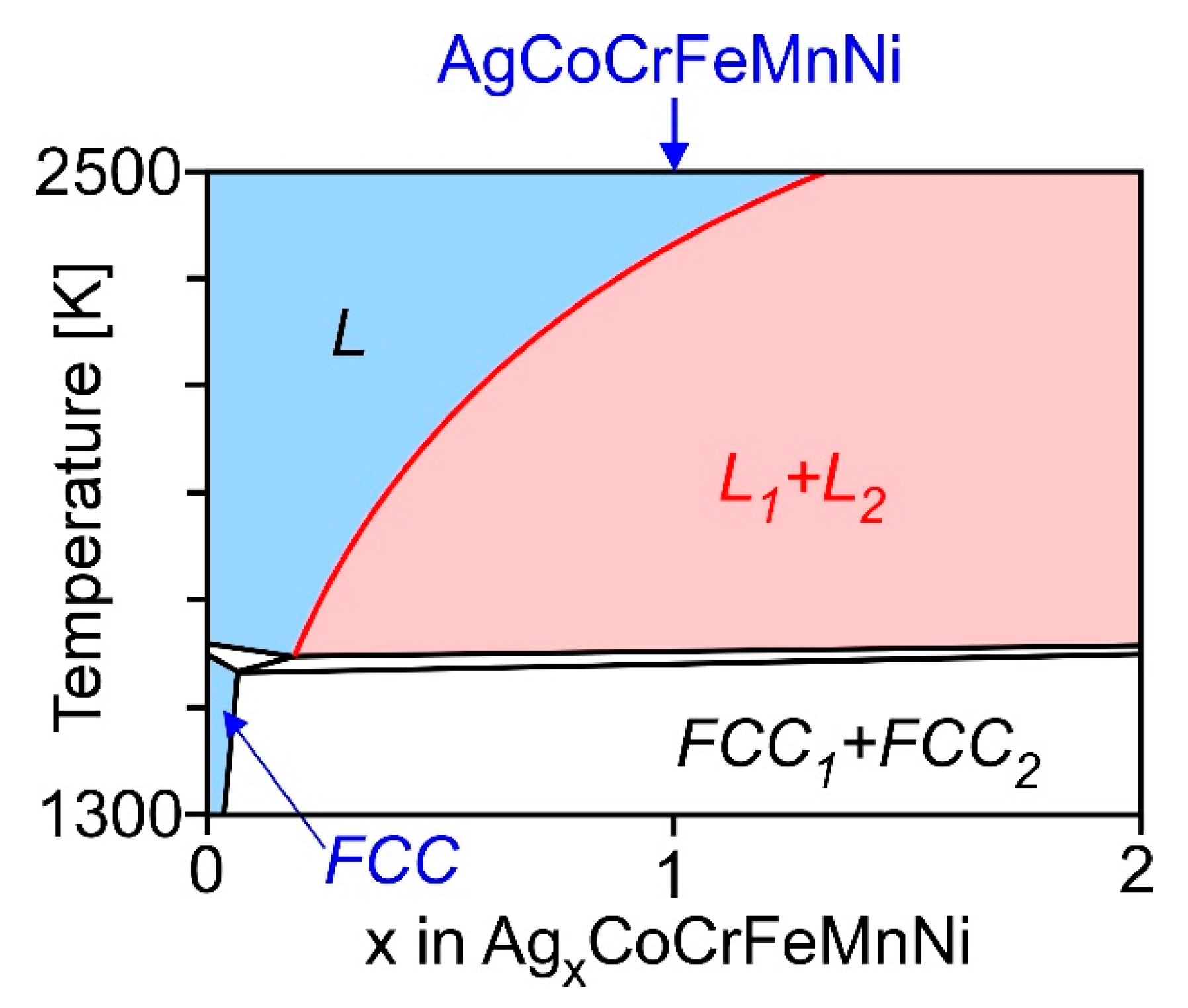
LPS was observed in the arc-melted ingots of the equiatomic AgCoCrFeMnNi HEAs;
(2)
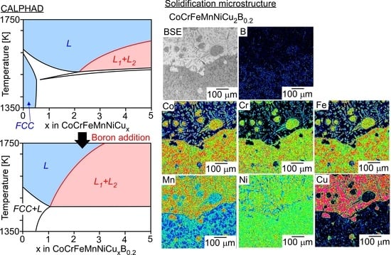
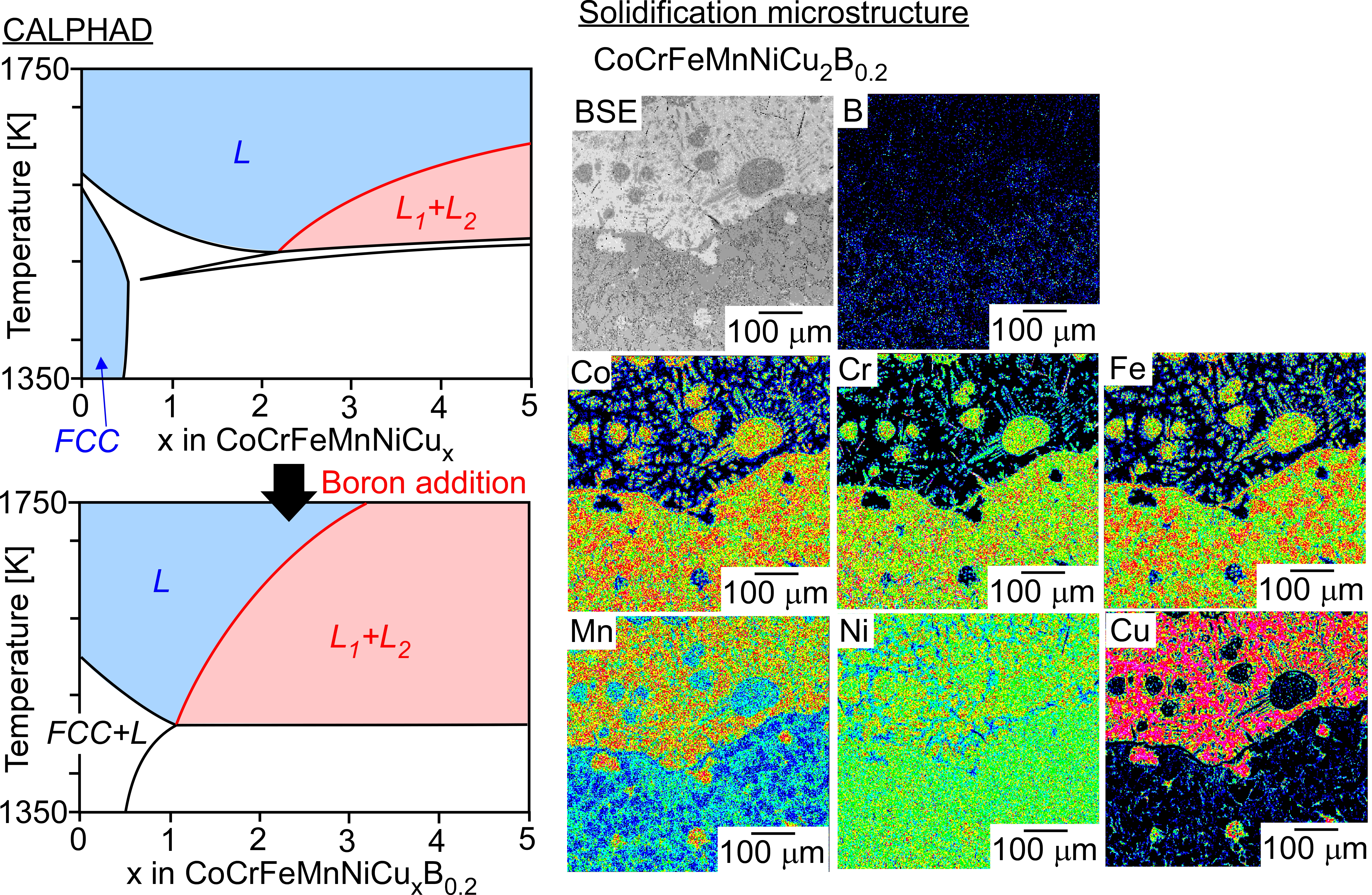
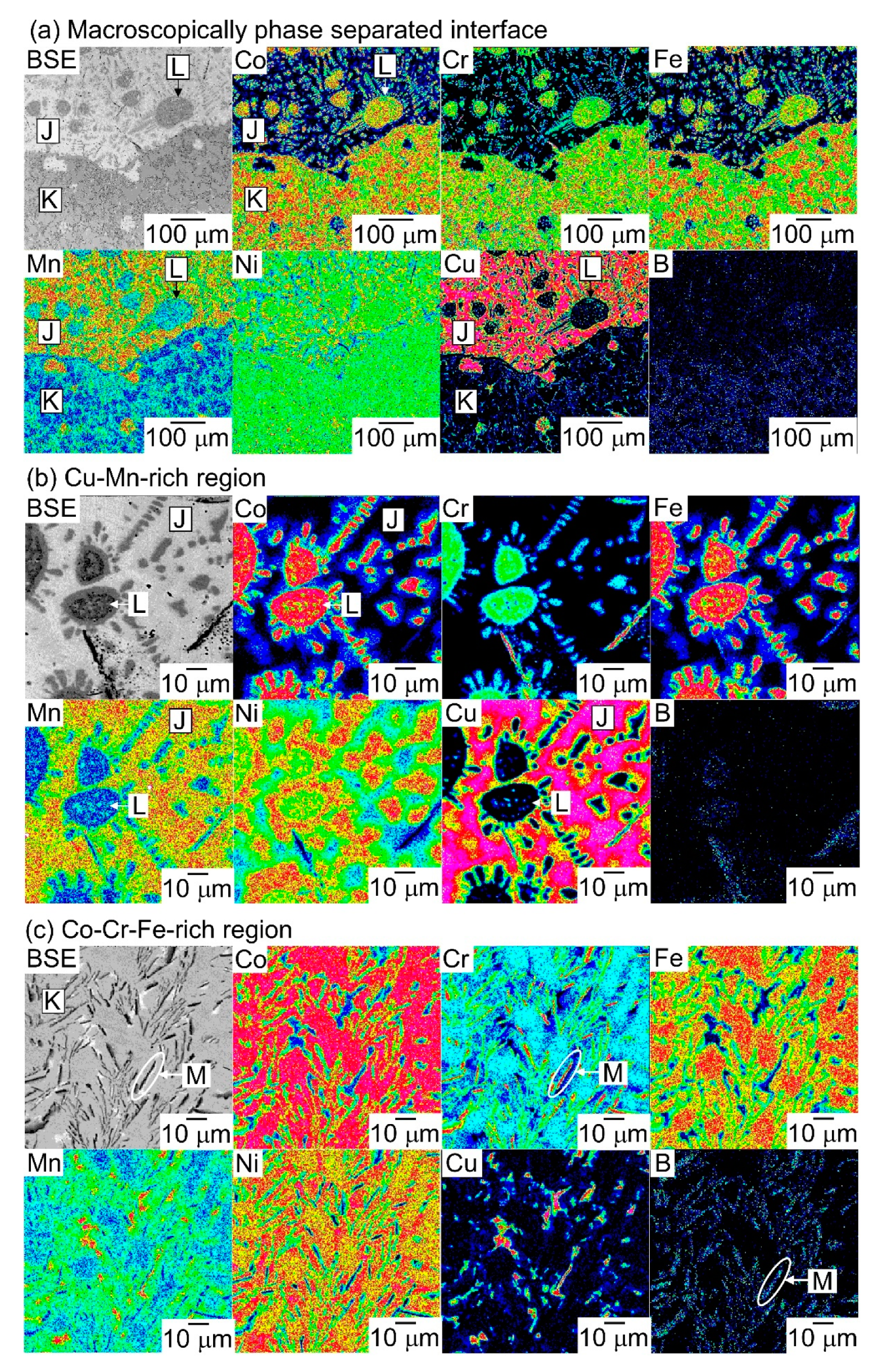
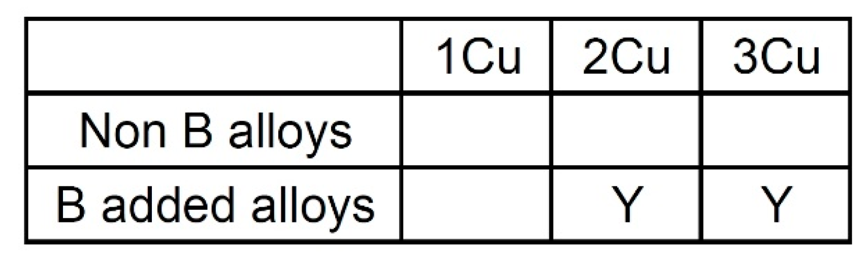
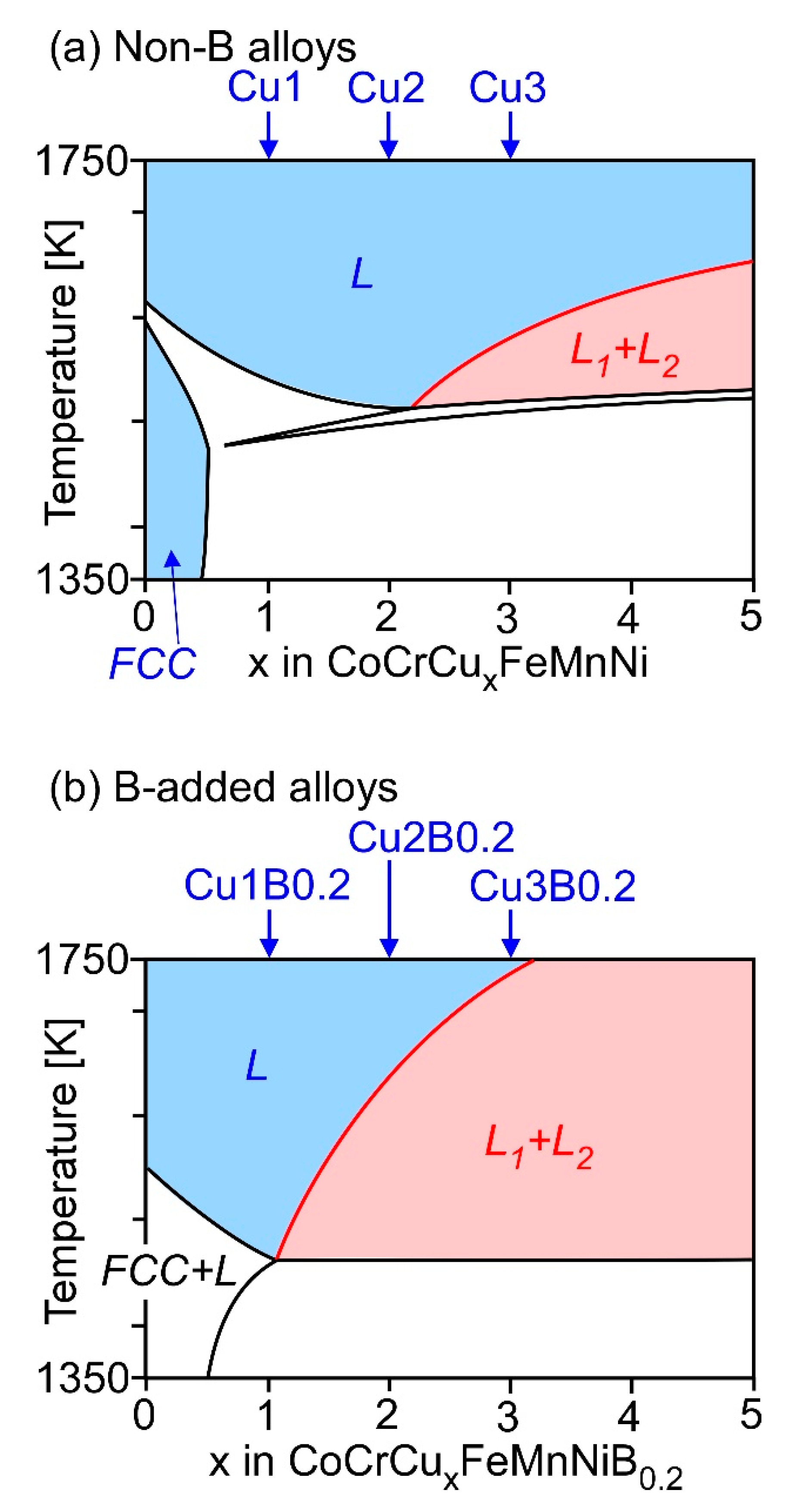
A macroscopically phase-separated structure formed via LPS was not observed in the arc-melted ingots of the CoCrCuxFeMnNi (x = 1, 2, 3) HEAs, whereas LPS was observed in the arc-melted ingots of the B-added CoCrCuxFeMnNiB0.2 (x = 2, 3) HEAs. The addition of B enhanced the LPS tendency in the CoCrFeMnNiCux HEAs;
(3)
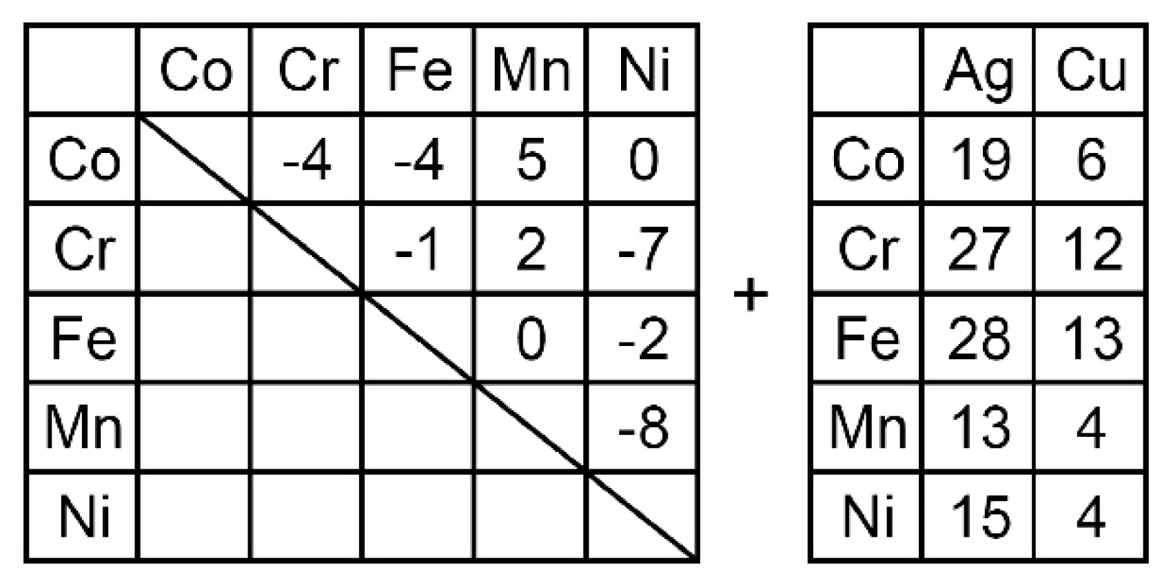
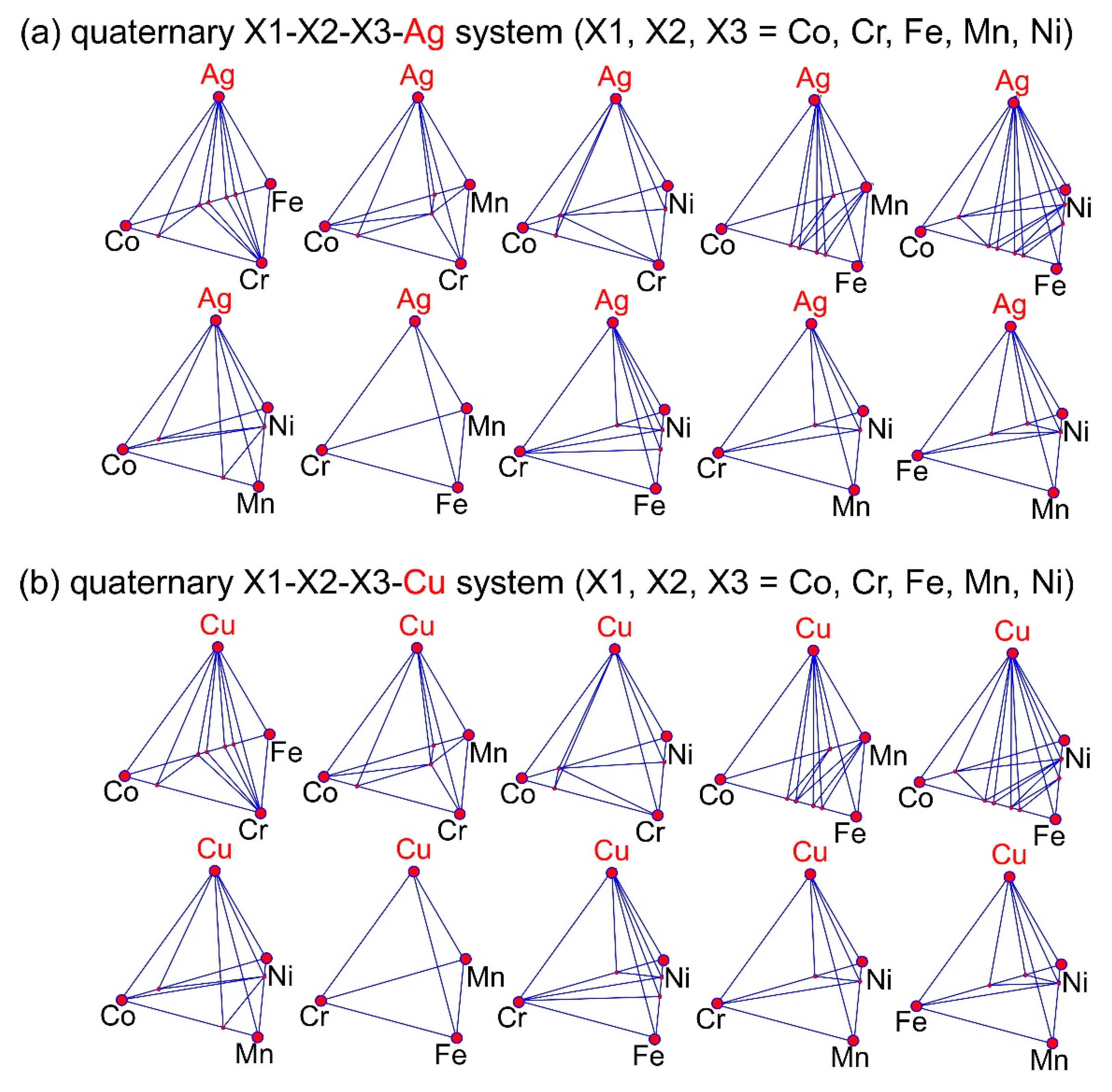
The occurrence of LPS in the arc-melted ingots of the Ag-Co-Cr-Fe-Mn-Ni and Co-Cr-Cu-Fe-Mn-Ni-B HEAs corresponded to the positive values of Hi-j (i = Ag)(j = Co, Cr, Fe, Mn, Ni) and Hi-j (i = Cu)(j = Co, Cr, Fe, Mn, Ni), the absence of Ag-containing and Cu-containing intermetallic compounds in the predicted phase diagrams, and the liquid miscibility gap in the calculated phase diagrams.

Author Contributions

Investigation, T.N. (Takeshi Nagase) and M.T.; original draft, T.N. (Takeshi Nagase); supervision, T.N. (Takayoshi Nakano); review and editing, T.N. (Takayoshi Nakano). All authors have read and agreed to the published version of the manuscript.

Funding

This work was partially funded by JSPS KAKENHI (Grant Number 18H05254, 18K04750, and 19H05172). This work was also partly supported by the Cross Ministerial Strategic Innovation Promotion Program (SIP), “Materials Integration for Revolutionary Design System of Structural Materials” from the Japan Science and Technology Agency (JST) and “Innovative Design/Manufacturing Technologies” from the New Energy and Industrial Technology Development Organization (NEDO).

Conflicts of Interest

The authors declare no conflict of interest.

References

  1. Devine, T.M.; Kummer, F.J.; Wulff, J. Wrought cobalt-chromium surgical implant alloys. J. Mater. Sci. 1972, 7, 126–128. [Google Scholar] [CrossRef]
  2. Devine, T.M.; Wulff, J. Cast vs. wrought cobalt-chromium surgical implant alloys. J. Biomed. Mater. Res. 1975, 9, 151–167. [Google Scholar] [CrossRef] [PubMed]
  3. Cohen, J.; Rose, R.M.; Wulff, J. Recommended heat treatment and alloy additions for cast Co-Cr surgical implants. J. Biomed. Mater. Res. 1978, 12, 935–937. [Google Scholar] [CrossRef] [PubMed]
  4. Kilner, T.; Pilliar, R.M.; Weatherly, G.C.; Alibert, C. Phase identification and incipient melting in a cast Co-Cr surgical implant alloy. J. Biomed. Mater. Res. 1982, 16, 63–79. [Google Scholar] [CrossRef] [PubMed]
  5. Niinomi, M. Recent metallic materials for biomedical applications. Metall. Mater. Trans. A 2002, 33, 477–486. [Google Scholar] [CrossRef]
  6. Niinomi, M.; Nakai, M.; Hieda, J. Development of new metallic alloys for biomedical applications. Acta Biomater. 2012, 8, 3888–3903. [Google Scholar] [CrossRef]
  7. Niinomi, M. Design and development of metallic biomaterials with biological and mechanical biocompatibility. J. Biomed. Mater. Res. A 2019, 107, 944–954. [Google Scholar] [CrossRef]
  8. Cantor, B.; Chang, I.T.H.; Knight, P.; Vincent, A.J.B. Microstructural development in equiatomic multicomponent alloys. Mater. Sci. Eng. A 2004, 375, 213–218. [Google Scholar] [CrossRef]
  9. Yeh, J.W.; Chen, S.K.; Lin, S.J.; Gan, J.Y.; Chin, T.S.; Shun, T.T.; Tsau, C.H.; Chang, S.Y. Nanostructured high-entropy alloys with multiple principal elements: Novel alloy design concepts and outcomes. Adv. Eng. Mater. 2004, 6, 299–303. [Google Scholar] [CrossRef]
  10. Ranganathan, S. Alloyed pleasures: Multimetallic cocktails. Curr. Sci. 2003, 85, 1404–1406. [Google Scholar]
  11. Zhang, Y.; Zhou, Y.J.; Lin, J.P.; Chen, G.L.; Liew, P.K. Solid-solution phase formation rules for multi-component alloys. Adv. Eng. Mater. 2008, 10, 534–538. [Google Scholar] [CrossRef]
  12. Yeh, J.W. Alloy design strategies and future trends in high-entropy alloys. JOM 2013, 65, 1759–1771. [Google Scholar] [CrossRef]
  13. Tsai, M.H.; Yeh, J.W. High-entropy alloys: A critical review. Mater. Res. Lett. 2014, 2, 107–123. [Google Scholar] [CrossRef]
  14. Zhang, Y.; Zuo, T.T.; Tang, Z.; Gao, M.C.; Dahmen, K.A.; Liaw, P.K.; Lu, Z.P. Microstructures and properties of high-entropy alloys. Prog. Mater. Sci. 2014, 61, 1–93. [Google Scholar] [CrossRef]
  15. Murty, B.S.; Yeh, J.W.; Ranganathan, S. High-entropy Alloys, 1st ed.; Elsevier: Amsterdam, Nederland, 2014. [Google Scholar]
  16. Gao, M.C.; Yeh, J.-W.; Liaw, P.K.; Zhang, Y. High-Entropy Alloys, Fundamentals and Applications, 1st ed.; Springer: Berlin, Germany, 2016. [Google Scholar]
  17. Takeuchi, A. Alloy designs for high-entropy alloys, bulk metallic glasses and high-entropy bulk metallic glasses. J. Jpn. Inst. Met. 2015, 79, 157–168. [Google Scholar] [CrossRef] [Green Version]
  18. Takechi, A. Recent progress in alloy designs for high-entropy crystalline and glassy alloys. J. Jpn. Soc. Powder. Met. 2016, 63, 209–216. [Google Scholar] [CrossRef] [Green Version]
  19. Ye, Y.F.; Wang, Q.; Lu, J.; Liu, C.T.; Yang, Y. High-entropy alloy: Challenges and prospects. Mater. Today 2016, 19, 349–362. [Google Scholar] [CrossRef]
  20. Miracle, D.B.; Senkov, O.N. A critical review of high entropy alloys and related concepts. Acta Mater. 2017, 122, 448–511. [Google Scholar] [CrossRef] [Green Version]
  21. Zhang, W.; Liew, P.K.; Zhang, Y. Science and technology in high-entropy alloys. Sci. China Mater. 2018, 61, 2–22. [Google Scholar] [CrossRef] [Green Version]
  22. Miracle, D.B. High entropy alloys as a bold step forward in alloy development. Nat. Commun. 2019, 10, 1805. [Google Scholar] [CrossRef]
  23. Nagase, T.; Todai, M.; Nakano, T. Development of Co-Cr-Mo-Fe-Mn-W and Co-Cr-Mo-Fe-Mn-W-Ag high-entropy alloys based on Co-Cr-Mo alloys. Mater. Trans. 2020, 61, 567–576. [Google Scholar] [CrossRef] [Green Version]
  24. Todai, M.; Nagase, T.; Hori, T.; Matsugaki, A.; Sekita, A.; Nakano, T. Novel TiNbTaZrMo high-entropy alloys for metallic biomaterials. Scr. Mater. 2017, 129, 65–68. [Google Scholar] [CrossRef] [Green Version]
  25. Wang, S.P.; Xu, J. TiZrNbTaMo high-entropy alloy designed for orthopedic implants: As-cast microstructure and mechanical properties. Mater. Sci. Eng. C 2017, 73, 80–89. [Google Scholar] [CrossRef] [PubMed]
  26. Nagase, T.; Mizuuchi, K.; Nakano, T. Solidification microstructures of the ingots obtained by arc melting and cold crucible levitation melting in TiNbTaZr medium-entropy alloy and TiNbTaZrX (X = V, Mo, W) high-entropy alloys. Entropy 2019, 21, 483. [Google Scholar] [CrossRef] [Green Version]
  27. Nagase, T.; Todai, M.; Hori, T.; Nakano, T. Microstructure of equiatomic and non-equiatomic Ti-Nb-Ta-Zr-Mo high-entropy alloys for metallic biomaterials. J. Alloy. Compd. 2018, 753, 412–421. [Google Scholar] [CrossRef]
  28. Hori, T.; Nagase, T.; Todai, M.; Matsugaki, A.; Nakano, T. Development of Non-equiatomic Ti-Nb-Ta-Zr-Mo High-Entropy Alloys for Metallic Biomaterials. Scr. Mater. 2019, 172, 83–87. [Google Scholar] [CrossRef]
  29. Yuan, Y.; Wu, Y.; Yang, Z.; Liang, X.; Lei, Z.; Huang, H.; Wang, H.; Liu, X.; An, K.; Wu, W.; et al. Formation, structure and properties of biocompatible TiZrHfNbTa high-entropy alloys. Mater. Res. Lett. 2019, 7, 225–231. [Google Scholar] [CrossRef] [Green Version]
  30. Motallebzadeh, A.; Peighambardoust, N.S.; Sheikh, S.; Murakami, H.; Guo, S.; Canadinc, D. Microstructural, mechanical and electrochemical characterization of TiZrTaHfNb and Ti1.5ZrTa0.5Hf0.5Nb0.5 refractory high-entropy alloys for biomedical applications. Intermet. 2019, 113, 106572. [Google Scholar] [CrossRef]
  31. Popescu, G.; Ghiban, B.; Popescu, C.A.; Rosu, L.; Trusca, R.; Carcea, I.; Soare, V.; Dumitrescu, D.; Constantin, I.; Olaru, M.T.; et al. New TiZrNbTaFe high entropy alloy used for medical applications. IOP Conf. Ser. 2018, 400, 022049. [Google Scholar]
  32. Nagase, T.; Iijima, Y.; Matsugaki, A.; Ameyama, K.; Nakano, T. Design and fabrication of Ti-Zr-Hf-Cr-Mo and Ti-Zr-Hf-Co-Cr-Mo high-entropy alloys as metallic biomaterials. Mater. Sci. Eng. C 2020, 107, 110322. [Google Scholar] [CrossRef]
  33. Hsu, U.S.; Hung, U.D.; Yeh, J.W.; Chen, S.K.; Huang, Y.S.; Yang, C.C. Alloying behavior of iron, gold and silver in AlCoCrCuNi-based equimolar high-entropy alloys. Mater. Sci. Eng. A 2007, 460, 403–408. [Google Scholar] [CrossRef]
  34. Guo, S.; Ng, C.; Liu, C.T. Anomalous solidification microstructures in Co-free AlxCrCuFeNi2 high-entropy alloy. J. Alloy. Compd. 2013, 557, 77–81. [Google Scholar] [CrossRef]
  35. Munitz, A.; Samuha, S.; Brosh, E.; Salhov, S.; Derimow, N.; Abbaschian, R. Liquid phase separation phenomena in Al2.2CrCuFeNi2 HEA. Intermet 2018, 97, 77–84. [Google Scholar] [CrossRef]
  36. Munitz, A.; Kaufman, M.J.; Chandler, J.P.; Kalaantari, H.; Abbaschian, R. Melt separation phenomena in CoNiCuAlCr high entropy alloy containing silver. Mater. Sci. Eng. A 2013, 560, 633–642. [Google Scholar] [CrossRef]
  37. Wu, P.H.; Liu, N.; Yang, W.; Zhu, Z.X.; Lu, Y.P.; Wang, X.J. Microstructure and solidification behavior of multicomponent CoCrCuxFeMoNi high-entropy alloys. Mater. Sci. Eng. A 2015, 642, 142–149. [Google Scholar] [CrossRef]
  38. Liu, N.; Wu, P.H.; Zhou, P.J.; Peng, Z.; Wang, X.J.; Lu, Y.P. Rapid solidification and liquid-phase separation of undercooled CoCrCuFexNi high-entropy alloys. Intermet 2016, 72, 44–52. [Google Scholar] [CrossRef]
  39. Wu, P.H.; Liu, N.; Zhou, P.J.; Peng, Z.; Du, W.D.; Wang, X.J.; Pan, Y. Microstructures and liquid phase separation in multicomponent CoCrCuFeNi high entropy alloys. Mater. Sci. Technol. 2016, 32, 576–580. [Google Scholar] [CrossRef]
  40. Wang, W.L.; Hu, L.; Luo, S.B.; Meng, L.J.; Geng, D.L.; Wei, B. Liquid phase separation and rapid dendritic growth of high-entropy CoCrCuFeNi alloy. Intermet 2016, 77, 41–45. [Google Scholar] [CrossRef]
  41. Guo, T.; Li, J.; Wang, J.; Wang, Y.; Kou, H.; Niu, S. Liquid-phase separation in undercooled CoCrCuFeNi high entropy alloy. Intermet 2017, 86, 110–115. [Google Scholar] [CrossRef]
  42. Peng, Z.; Liu, N.; Zhang, S.Y.; Wu, P.H.; Wang, X.J. Liquid-phase separation of immiscible CrCuxFeMoyNi high-entropy alloys. Mater. Sci. Technol. 2017, 33, 1352–1359. [Google Scholar] [CrossRef]
  43. Munitz, A.; Kaufman, M.J.; Abbaschian, R. Liquid phase separation in transition element high entropy alloys. Intermet 2017, 86, 59–72. [Google Scholar] [CrossRef]
  44. Wang, S.; Chen, Z.; Feng, L.C.; Liu, Y.Y.; Zhang, P.; Hea, Y.Z.; Menga, Q.Q.; Zhanga, J.Y. Nano-phase formation accompanying phase separation in undercooled CoCrCuFeNi-3 at.% Sn high entropy alloy. Mater. Charact. 2018, 144, 516–521. [Google Scholar] [CrossRef]
  45. Munitz, A.; Dry, I.E.; Brosh, E.; Derimow, N.; MacDonald, B.E.; Lavernia, E.J.; Abbaschian, R. Liquid phase separation in AlCrFeNiMo0.3 high-entropy alloy. Intermet 2019, 112, 106517. [Google Scholar] [CrossRef]
  46. Nagase, T.; Todai, M.; Nakano, T. Development of Ti-Zr-Hf-Y-La high-entropy alloys with dual hexagonal-close-packed structure. Scr. Mater. 2020, 186, 242–246. [Google Scholar] [CrossRef]
  47. Derimow, N.; Abbaschian, R. Liquid phase separation in high-entropy alloys—A review. Entropy 2018, 20, 890. [Google Scholar] [CrossRef] [Green Version]
  48. Gludovatz, B.; Hohenwarter, A.; Catoor, D.; Chang, E.H.; George, E.P.; Ritchie, R.O. A fracture-resistant high-entropy alloy for cryogenic applications. Science 2014, 345, 1153–1158. [Google Scholar] [CrossRef] [Green Version]
  49. Otto, F.; Dlouhy, A.; Somsen, C.; Bei, H.; Eggeler, G.; George, E.P. The influences of temperature and microstructure on the tensile properties of a CoCrFeMnNi high-entropy alloy. Acta Mater. 2013, 61, 5743–5755. [Google Scholar] [CrossRef] [Green Version]
  50. Karakaya, I.; Thompson, W.T. The Ag-Co (Silver-Cobalt) system. J. Phase Equilib. 1986, 7, 259–263. [Google Scholar] [CrossRef]
  51. Venkatraman, M.; Neumann, J.P. The Ag-Cr (Silver-Chromium) system. J. Phase Equilib. 1990, 11, 263–265. [Google Scholar] [CrossRef]
  52. Swartzendruber, L.J. The Ag-Fe (Silver-Iron) system. J. Phase Equilib. 1984, 5, 560–564. [Google Scholar] [CrossRef]
  53. Karakaya, I.; Thompson, W.T. The Ag-Mn (silver-manganese) system. J. Phase Equilib. 1990, 11, 480–486. [Google Scholar] [CrossRef]
  54. Singleton, M.; Nash, P. The Ag-Ni (Silver-Nickel) system. J. Phase Equilib. 1987, 8, 119–121. [Google Scholar] [CrossRef]
  55. Nishizawa, T.; Ishida, K. The Co-Cu (Cobalt-Copper) system. J. Phase Equilib. 1984, 5, 161–165. [Google Scholar] [CrossRef]
  56. Chen, Q.; Jin, Z.P. The Fe-Cu system: A thermodynamic evaluation. Met. Trans. A 1995, 26, 417–426. [Google Scholar] [CrossRef]
  57. Wang, C.P.; Liu, X.J.; Ohnuma, I.; Kainuma, R.; Ishida, K. Thermodynamic database of the phase diagrams in Cu-Fe base ternary systems. J. Phase Equilib. Diffus. 2004, 25, 320–328. [Google Scholar] [CrossRef]
  58. Okamoto, H. Cr-Cu (chromium-copper). J. Phase Equilib. Diffus. 2012, 33, 342–343. [Google Scholar] [CrossRef]
  59. Nakagawa, Y. Liquid immiscibility in copper-iron and copper-cobalt systems in the supercooled state. Acta Met. 1958, 6, 704–711. [Google Scholar] [CrossRef]
  60. Sun, Z.B.; Wang, Y.H.; Guo, J. Liquid phase separation of Cu-Cr alloys during rapid cooling. Trans. Nonferrous Met. Soc. China 2006, 16, 998–1002. [Google Scholar] [CrossRef]
  61. Wei, X.; Wang, J.; Yang, Z.; Sun, Z.; Yu, D.; Song, X.; Ding, B.; Yang, S. Liquid phase separation of Cu-Cr alloys during the vacuum breakdown. J. Alloy Compd. 2015, 509, 7116–7120. [Google Scholar] [CrossRef]
  62. Si, S.H.; Zhang, H.; He, Y.Z.; Li, M.X.; Guo, S. Liquid phase separation and the aging effect on mechanical and electrical properties of laser rapidly solidified Cu100-XCrx alloys. Metals 2015, 5, 2119–2127. [Google Scholar] [CrossRef] [Green Version]
  63. Zhang, L.; Yu, G.; Tian, C.; He, X.; Li, S. Grain refinement of hypereutectic immiscible cu-50cr alloy during rapid melting and solidification induced by high power density laser beams. Met. 2019, 9, 585. [Google Scholar] [CrossRef] [Green Version]
  64. Yamauchi, I.; Ueno, N.; Shimaoka, M.; Ohnaka, I. Undercooling in Co-Cu alloys and its effect on solidification structure. J. Mater. Sci. 1998, 33, 371–378. [Google Scholar] [CrossRef]
  65. Nagase, T.; Yokoyama, A.; Umakoshi, Y. Formation of macroscopically phase separated cu-colored melt-spun ribbon in (Fe0.5Cu0.5)100-xBx (x = 0, 5, 10, and 20) alloys. J. Alloy. Compd. 2011, 509, 1178–1186. [Google Scholar] [CrossRef]
  66. Takeuchi, A.; Inoue, A. Classification of bulk metallic glasses by atomic size difference, heat of mixing and period of constituent elements and its application to characterization of the main alloying element. Mater. Trans. 2005, 46, 2817–2829. [Google Scholar] [CrossRef] [Green Version]
  67. Jain, A.; Hautier, G.; Moore, C.; Ong, S.P.; Fischer, C.; Mueller, T.; Persson, K.; Ceder, G. A high-throughput infrastructure for density functional theory calculations. Comp. Mater. Sci. 2011, 50, 2295–2310. [Google Scholar] [CrossRef]
  68. Chuang, Y.Y.; Schmid, R.; Chang, Y.A. Thermodynamic analysis of the iron-copper system I: The stable and metastable phase equilibria. Met. Trans. A 1984, 15, 1921–1930. [Google Scholar] [CrossRef]
  69. Wilde, G.; Willnecker, R.; Singh, R.N.; Sommer, F. The metastable miscibility gap in the system Fe-Cu. Z. Met. 1997, 88, 804–809. [Google Scholar]
  70. Turchanin, M.A.; Agraval, P.G.; Nikolaenko, I.V. Thermodynamics of alloys and phase equilibria in the copper-iron system. J. Phase Equilib. 2003, 24, 305–319. [Google Scholar] [CrossRef]
  71. Nagase, T.; Suzuki, M.; Tanaka, T. Formation of amorphous phase with crystalline globules in Fe-Cu-Nb-B immiscible alloys. J. Alloy. Compd. 2015, 619, 267–274. [Google Scholar] [CrossRef]
  72. Nagase, T.; Suzuki, M.; Tanaka, T. Formation of amorphous phase with crystalline globules in Fe-Cu-Si-B and Fe-Cu-Zr-B immiscible alloys. Intermet. 2015, 61, 56–65. [Google Scholar] [CrossRef]
  73. Nagase, T.; Suzuki, M.; Tanaka, T. Amorphous phase formation in Fe-Ag-based immiscible alloys. J. Alloy. Compd. 2015, 619, 311–318. [Google Scholar] [CrossRef]
  74. Nagase, T.; Umakoshi, Y. Amorphous phase formation in Co-Cu-Zr-B-based immiscible alloys. J. Alloy. Compd. 2015, 649, 1174–1181. [Google Scholar] [CrossRef]
  75. Nagase, T.; Takemura, M.; Matsumuro, M.; Matsumoto, M.; Fujii, Y. Design and microstructure analysis of globules in Al-Co-La-Pb immiscible alloys with an amorphous phase. Mater. Des. 2017, 117, 338–345. [Google Scholar] [CrossRef]
  76. Nagase, T.; Terai, T.; Kakeshita, T.; Matsumoto, M.; Fujii, Y. Microstructure and magnetic properties of Cu-Ag-La-Fe immiscible alloys with an amorphous phase. Mater. Trans. 2019, 60, 554–560. [Google Scholar] [CrossRef] [Green Version]
  77. Nagase, T.; Matsumoto, M.; Fujii, Y. Microstructure of Ti-Ag immiscible alloys with liquid phase separation. J. Alloy. Compd. 2018, 738, 440–447. [Google Scholar] [CrossRef]
  78. Matyja, H.; Giessen, B.C.; Grant, N.J. The effect of cooling rate on the dendrite spacing in splat cooled aluminium alloys. J. inst. Met. 1968, 96, 30–32. [Google Scholar]
  79. Naka, M.; Shibayanagi, T. Formation and application of rapidly quenched metals. J. High Temp. Soc. 1998, 24, 131–136. [Google Scholar]
  80. Nagase, T.; Takemura, M.; Matsumuro, M.; Maruyama, T. Solidification microstructure of AlCoCrFeNi2.1 eutectic high entropy alloy ingots. Mater. Trans. 2018, 59, 255–264. [Google Scholar] [CrossRef] [Green Version]
  81. Nagase, T.; Kakeshita, T.; Matsumura, K.; Nakazawa, K.; Furuya, S.; Ozoe, N.; Yoshino, K. Development of Fe-Co-Cr-Mn-Ni-C high entropy cast iron (HE cast iron) available for casting in air atmosphere. Mater. Des. 2019, 184, 108172. [Google Scholar] [CrossRef]
  82. Momma, K.; Izumi, F. VESTA 3 for three-dimensional visualization of crystal, volumetric and morphology data. J. Appl. Crystallogr. 2011, 44, 1272–1276. [Google Scholar] [CrossRef]
  83. Laurent-Brocq, M.; Akhatova, A.; Perriere, L.; Chebini, S.; Sauvage, X.; Leroya, E.; Champion, Y. Insights into the phase diagram of the CrMnFeCoNi high entropy alloy. Acta Mater. 2015, 88, 355–365. [Google Scholar] [CrossRef]
  84. Tong, C.J.; Chen, Y.L.; Yeh, J.W.; Lin, S.J.; Chen, S.K.; Shun, T.T.; Tsau, C.H.; Chang, S.-Y. Microstructure characterization of AlxCoCrCuFeNi high-entropy alloy system with multiprincipal elements. Met. Mater. Trans. A 2005, 36, 881–893. [Google Scholar] [CrossRef]
Figure 1. Mixing enthalpy (ΔHi-j) at binary i-j pairs among Ag, Co, Cr, Cu, Fe, Mn, and Ni.
Crystals 10 00527 g001
Figure 2. Predicted quaternary phase diagrams constructed by the Materials Project. (a) X1-X2-X3-Ag (X1, X2, X3 = Co, Cr, Fe, Mn, Ni) alloy systems based on the Ag-Co-Cr-Fe-Mn-Ni alloy system, (b) X1-X2-X3-Cu (X1, X2, X3 = Co, Cr, Fe, Mn, Ni) alloy systems based on the Co-Cr-Cu-Fe-Mn-Ni alloy system.
Crystals 10 00527 g002
Figure 3. XRD pattern of arc-melted ingots in the equiatomic AgCoCrFeMnNi high-entropy alloy (HEA).
Crystals 10 00527 g003
Figure 4. SEM-BSE image of the arc-melted ingots of the equiatomic AgCoCrFeMnNi HEA with a macroscopic phase-separated structure. (b) is the magnified image of (a) focusing on the macroscopically phase-separated interface.
Crystals 10 00527 g004
Figure 5. Element mapping of the arc-melted ingots in the equiatomic AgCoCrFeMnNi HEA with a macroscopic phase-separated structure using electron probe microanalysis-wave dispersive spectroscopy (EPMA-WDS). (a) Element mapping focusing on the macroscopically phase-separated interface, (b) element mapping focusing on the Co-Cr-Fe-Mn-Ni-rich region (index A in Figure 5a).
Crystals 10 00527 g005
Figure 6. XRD pattern of the arc-melted ingots of the non-B CoCrCuxFeMnNi (x = 1, 2, 3) (Cu1, Cu2 Cu3) HEAs and B-added CoCrCuxFeMnNiB0.2 (x = 1, 2, 3) (Cu1B02, Cu2B02 Cu3B02) HEAs. (a) Non-B CoCrCuxFeMnNi (x = 1, 2, 3) (Cu1, Cu2 Cu3) HEAs, (b) B-added CoCrCuxFeMnNiB0.2 (x = 1, 2, 3) (Cu1B02, Cu2B02 Cu3B02) HEAs.
Crystals 10 00527 g006
Figure 7. SEM-BSE images of the arc-melted ingots of the non-B CoCrCuxFeMnNi (x = 1, 2, 3) (Cu1, Cu2 Cu3) HEAs. (a) Cu1, (b) Cu2, (c) Cu3.
Crystals 10 00527 g007
Figure 8. SEM-BSE images of the arc-melted ingots of the B-added CoCrCuFeMnNiB0.2 (Cu1B02) HEAs. (a) Low-magnification image, (b,c) magnified image of Figure 8a.
Crystals 10 00527 g008
Figure 9. Element mapping of the arc-melted ingots of the B-added CoCrCuFeMnNiB0.2 (Cu1B02) using EPMA-WDS. (a) Cu element mapping focusing of region G as depicted in Figure 8a, (b) element mapping corresponding to Figure 8b.
Crystals 10 00527 g009
Figure 10. SEM-BSE images of the arc-melted ingots of the B-added CoCrCuxFeMnNiB0.2 (x = 2, 3) (Cu2B02, Cu3B02) HEAs with a macroscopic phase-separated structure. (a) Cu2B02, (b) Cu3B02, (a2) and (a3) are magnified images of (a1,b2,b3) are magnified images of (b1).
Crystals 10 00527 g010
Figure 11. Element mapping of the arc-melted ingots of the B-added CoCrCu2FeMnNiB0.2 (Cu2B02) HEA with a macroscopic phase-separated structure analyzed using EPMA-WDS, as the typical example of the solidification microstructure of Co-Cr-Cu-Fe-Mn-Ni-B HEAs with a macroscopically phase-separated structure. (a) Element mapping focusing on the macroscopically phase-separated interface, (b) element mapping focusing on the Cu-Mn-rich region (J in Figure 11a), (c) element mapping focusing on the Co-Cr-Fe-rich region (K in Figure 11a).
Crystals 10 00527 g011
Figure 12. Liquid phase separation (LPS) tendency in the Co-Cr-Cu-Fe-Mn-Ni and Co-Cr-Cu-Fe-Mn-Ni-B HEAs focusing on the existence of B and Cu concentrations.
Crystals 10 00527 g012
Figure 13. Calculated phase diagram of the pseudo-binary CoCrFeMnNi-Ag2CoCrFeMnNi focusing on LPS. The liquid miscibility gap is shown using the red line.
Crystals 10 00527 g013
Figure 14. Calculated phase diagram of the pseudo-binary CoCrFeMnNi-CoCrCu5FeMnNi and CoCrFeMnNiB0.2-CoCrCu5FeMnNiB0.2 focusing on LPS. The liquid miscibility gap is shown using a red line. (a) CoCrFeMnNi-CoCrCu5FeMnNi and (b) CoCrFeMnNiB0.2-CoCrCu5FeMnNiB0.2.
Crystals 10 00527 g014
Table 1. Composition and alloy abbreviation investigated in the present study. (a) Atomic ratio, (b) atomic percent (at %).
(a) Atomic Ratio
Alloy abbreviationAgCoCrCuFeMnNiB
Ag111 111
Cu1 111111
Cu2 112111
Cu3 113111
Cu1B02 1111110.2
Cu2B02 1121110.2
Cu2B02 1131110.2
(b) Atomic Percent
Alloy abbreviationAgCoCrCuFeMnNiB
Ag16.6716.6716.67 16.6716.6716.67
Cu1 16.6716.6716.6716.6716.6716.67
Cu2 14.2914.2928.5714.2914.2914.29
Cu3 12.5012.5037.5012.5012.5012.50
Cu1B02 16.1316.1316.1316.1316.1316.133.23
Cu2B02 13.8913.8927.7813.8913.8913.892.78
Cu2B02 12.2012.2036.5912.2012.2012.202.44
Table 2. Chemical composition analysis results of the ratio of metallic element without considering B (atomic percent ratio) in the arc-melted ingots of the CoCrCuFeMnNiB0.2 (Cu1B02) HEA evaluated using WDS.
PositionCoCrCuFeMnNi
G2.91.857.32.223.212.7
H21.120.79.122.110.516.4
Table 3. Chemical composition analysis results of the ratio of metallic element without considering B (atomic percent ratio) in the CoCrCu2FeMnNiB0.2 (Cu2B02) HEA evaluated by WDS.
PositionCoCrCuFeMnNi
K22.921.56.624.29.515.2
J2.11.264.91.620.110.0
L21.224.37.921.510.714.5
Table 4. Chemical composition of the separated liquid in CoCrCu2FeMnNiB0.2 (Cu2B02) alloys estimated by the thermodynamic calculations. (a) Cu-rich liquids, (b) Cu-poor liquids.
(a) Cu2B02, Cu-rich liquid
Temp. [K]CoCrCuFeMnNiB
15004.53.367.83.613.17.20.4
14003.12.173.82.312.56.00.2
(b) Cu2B02, Cu-poor liquid
Temp. [K]CoCrCuFeMnNiB
150015.315.521.915.414.014.93.1
140016.716.915.916.914.315.93.4

