Article

The Effect of Printing Parameters on Electrical Conductivity and Mechanical Properties of PLA and ABS Based Carbon Composites in Additive Manufacturing of Upper Limb Prosthetics

1
3D Printing and Visualization Centre, University of Pécs, Boszorkany str. 2, H-7624 Pécs, Hungary
2
Department of Biophysics, Medical School, University of Pécs, Szigeti str. 12, H-7624 Pécs, Hungary
3
MTA-PTE Nuclear-Mitochondrial Interactions Research Group, H-7624 Pécs, Hungary
4
Department of Technical Informatics, Faculty of Engineering and Information Technology, University of Pécs, Boszorkány str. 2, H-7624 Pécs, Hungary
5
Central Electron Microscope Laboratory, Medical School, University of Pécs, Szigeti str. 12, H-7624 Pécs, Hungary
*
Author to whom correspondence should be addressed.
Crystals 2020, 10(5), 398; https://doi.org/10.3390/cryst10050398
Submission received: 4 April 2020 / Revised: 11 May 2020 / Accepted: 12 May 2020 / Published: 15 May 2020

Abstract

:
Additive manufacturing technologies are dynamically developing, strongly affecting almost all fields of industry and medicine. The appearance of electrically conductive polymers has had a great impact on the prototyping process of different electrical components in the case of upper limb prosthetic development. The widely used FFF 3D printing technology mainly uses PLA (polylactic acid) and ABS (acrylonitrile butadiene styrene) based composites, and despite their presence in the field, a detailed, critical characterization and comparison of them has not been performed yet. Our aim was to characterize two PLA and ABS based carbon composites in terms of electrical and mechanical behavior, and extend the observations with a structural and signal transfer analysis. The measurements were carried out by changing the different printing parameters, including layer resolution, printing orientation and infill density. To determine the mechanical properties, static and dynamic tests were conducted. The electrical characterization was done by measuring the resistance and signal transfer characteristics. Scanning electron microscopy was used for the structural analysis. The results proved that the printing parameters had a significant effect on the mechanical and electrical characteristics of both materials. As a major novelty, it was concluded that the ABS carbon composite has more favorable behavior in the case of additive manufacturing of electrical components of upper limb prosthetics, and they can be used as moving, rotating parts as well.

1. Introduction

Limb loss affects more than 3–5 million people worldwide [1]. It is estimated that more than 3.5 million people will have this condition by 2050, only in the United States [2]. Upper limb loss represents a smaller percentage among this condition [3], but highly impacts the quality of living and functionality of the patients, and devices must be continuously developed to reduce prosthetic abandonment [4,5]. Developing highly functional devices is the key factor towards regaining the functionality of the affected clients, alongside with proper rehabilitation methods. Additive manufacturing technologies are ideal for product development, rapid prototyping (RPT) and small series production [6,7,8]. Tinkers, researchers and physicians use 3D printers on a daily basis to create and visualize their ideas, concepts, products or models. The most common technology is desktop FFF or FDM 3D printing worldwide. The devices are cost-effective, and easy to operate and maintain. The variety of materials are relatively high; thermoplastic polymers like TPU (thermoplastic polyurethane) and PMMA (poly-methyl acrylate) can be easily printed but the most frequently used and well-known materials are PLA (polylactic acid) and ABS (acrylonitrile butadiene styrene) [9]. In upper limb prosthetic development, FFF 3D printers are frequently used [10,11]. They can be used for printing sockets or other mechanical parts [10,11], but different electrical components can also be manufactured by 3D printing. [12,13]. Relevant research can be found in reference to the characterization of FFF printed resistors [14], in which conductive PLA resistance tests were made originating from the X, Y and Z printing orientation. The 3D printing of electronic sensors appears to hold promise according to the work of R.J.B Simon et al. [15], in which a low-cost conductive composite material (“carbomorph”) was presented. The rapid prototyping of structural electronics [12], specifically, electrically conductive components using a carbon nanofiber (CNF) composite, is also possible [16]. High-content graphene scaffolds for electronic and biomedical applications [17] and a PLA conductive filament in support of smart sensing applications [18] have also been tested, and the results recently published. Furthermore, results were published regarding the manufacturability and resistivity of a conductive filament [19] in which the “Protopasta” conductive PLA filament was used, printing different specimens from certain directions, and analyzing the resistance values. The characterization and practical testing of electrically conductive PLA-graphene and PLA-carbon black (CB) composite filament was also formerly examined [20]. Despite the previous, extensive research work, the effects of printing parameters on electrical and signal processing properties have not been examined before. In addition, there are several valuable and highly detailed publications on the mechanical behavior of PLA and ABS composites and polymers [21,22,23,24], although torque measurements have not been carried out before, which are essential in terms of the moving parts like joints and wrists modules. In addition, according to our research, previous works have not compared the electrical behavior of these materials, nor the usability of them in upper limb prosthetic development. Our aim was to provide a practical, yet scientifically valid, detailed description about conductive ABS and PLA carbon filaments potentially suitable for prosthetic and other bionic or soft-robotic applications.

2. Materials and Methods

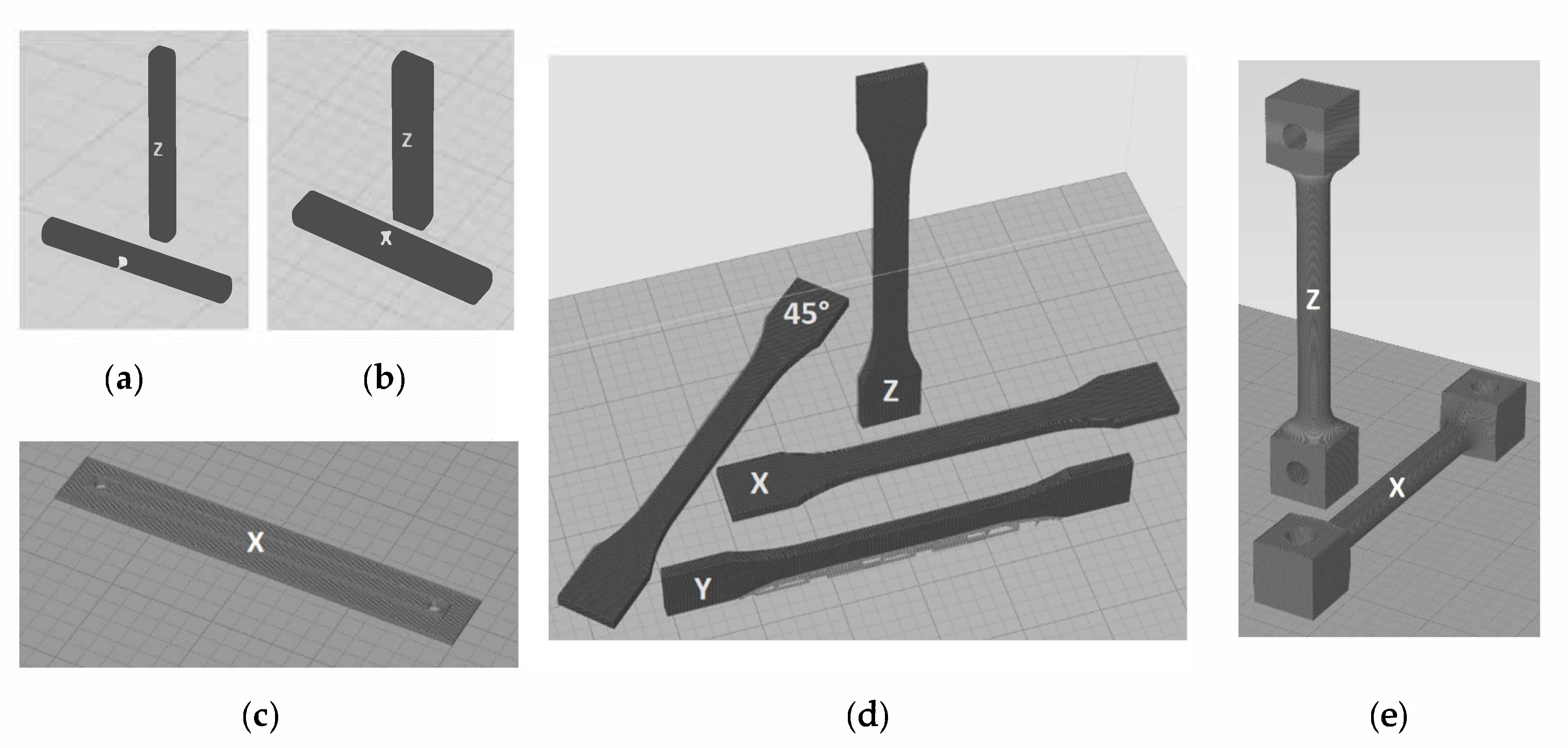
2.1. Printing of the Materials

The materials investigated in our research included PLA based carbon composites (ESD-PLA, manufactured by Philamania Ltd., 3527 Miskolc, József Attila Street 57) and ABS based carbon composites (ESD-ABS, distributed by HobbyKing®). The materials were procured in a filament form with a diameter of 1.75 mm, ideally suitable regarding Fused Filament Fabrication AM (additive manufacturing) technology. According to the technical data sheet, both materials were mixed with carbon yet in an unknown concentration. The samples for the experiments were printed using a nozzle diameter of 0.4 mm, with a Craftbot Plus desktop 3D printer (Craftunique Ltd, 1143 Budapest, Ilka Street 50). The specimens for the test with ESD-PLA were printed with a 210 °C hot-end and 50 °C printing bed temperature, set to a 60 mm/sec printing speed and with the default parameters (number of loop counts: 2; number of top and bottom layers: 3; type of printing: parallel line; type of infill: parallel line), all originating from CraftWare™ software (Figure 1). Supportive printing was implemented regarding the Y orientation for the tensile strength test. The material ESD-ABS was printed with a 240 °C hot-end and 100 °C printing bed temperature where the first layer was printed out with a 40 mm/sec printing speed; thereafter, a 60 mm/sec printing speed was used. The CraftWare™ software was used with the default parameters set as before.

2.2. Electrical Measurements

In reference to the electrical characterization of the materials, test specimens were manufactured using different printing parameters. First, the effect of the layer height on the resistance was evaluated. The size of the samples was 20 mm × 2 mm × 2 mm, and the printing resolution was set from 100 micrometers to 400 micrometers, with incremental steps consisting of 50 micrometers (Figure 1a). Six pieces were created from every test specimen, with a different layer height. At this point forward, the nomenclature refers to specimen “A.” The samples were also created in the X and Z printing orientations, respectively. In all cases, the infill density was 100%.
The dependence of resistance from the infill density was tested on specimens measuring 50 mm × 8 mm × 5 mm. The layer height varied from 100 to 400 micrometers with each step increasing 100 micrometers. Each sample was created with an infill density of 20%, 50% and 100% (Figure 1b), and from this point forward, the nomenclature refers to specimen “B.” To determine the effect of printing orientation, the specimens were also printed in the X and Z directions.
Standardized conductivity measurements were carried out using two ends of a multimeter including a pre-planned centralizer. Probes were attached at identical places on the endpoints of the specimens. To increase the accuracy and the reliability of the measurements, the implementation of a uniquely elaborated silver based connector was carried out. This ensured that the surface of the composite material was measured with far more precision. Four 1 mm x 1 mm silver marks were painted upon the four angles at the endpoints of the test bars. Copper wires were arranged on the silver painted surface. The resistance results measured between two endpoints of each specimen in random arrangement. The tests were performed in an ambient temperature of 27 °C and also in a cooling chamber at 3 °C, after tempering for 5 hours. All measurements were repeated in the span of 30 minutes. The accuracy of the applied multimeters (TEPCEL DMM-8062, UNI-T UT 33) was e = ±0.5%.

2.3. Mechanical Analysis

For mechanical testing, static and dynamic mechanical tests were performed. As static measurements, the 3-point bending test (ASTM D 790-03), tensile strength test (ASTM D 638-03) and Shore D hardness measurement (ISO 868) were carried out. Dimensions of the specimen at Shore D hardness were 5 mm x 10 mm x 10 mm. The Charpy impact tests were carried out using a testing device with a maximum measurement threshold of 1 J. The dynamic tests were conducted by the ISO-179-1 standard with 80 mm x 4 mm x 10 mm specimen dimensions. In all cases, the test specimens were printed out in the X, Y and Z directions with a 100 micron layer height and 100% infill, and to precisely determine the effect of printing orientation on the mechanical properties, the samples with direction X were also manufactured in a 45° orientation (Figure 1d). A torque test was carried out using the ISO 18338:2015 standard (Figure 1e). The diameter of the test specimen was 10 mm and the parallel length was 70 mm in this case. The speed of torsion was set to 36°/s. In this case, all the test bars were printed with 200 micrometers. The ambient temperature was 24 °C. All the tests were repeated 5 times, according to the standards.

2.4. Signal Transfer Capability

In the case of prosthetics, EMG signal transfer is essential to control the device. To determine the possibility of signal transfer with ESD-PLA and ESD-ABS materials, test specimens were created with the sizes of 100 mm x 5 mm x 1 mm (Figure 1c). All of them were manufactured with a 100, 200, 300 and 400 µm layer height as well. Excitation sinus-signals were transferred in the X direction, with different frequencies that varied between fe = 100 Hz and 500 kHz. The amplitude was set to Ue = 7.36 V. The means of attenuations were analyzed.

2.5. Scanning Electron Microscopy (SEM)

For SEM measurements (JEOL JSM 6300—Japan), with 60x, 200x and 1700x magnification, golden sheathing was applied on the specimen’s fracture surface. The broken surfaces were examined from every printing orientation and images were also made from non-printed (and fractured) conductive composite filaments.

2.6. Statistical Analysis

For testing the difference between the means of electrical and mechanical measurements, a two-sample t-test was used, with p = 0.05 significance level, in all cases. Standard deviation values were used as error rates. All graphs contain standard deviation values (error rates). Relative error rates are marked with “sr.” The statistical analysis was carried out using Origin Pro 2016 software.

3. Results

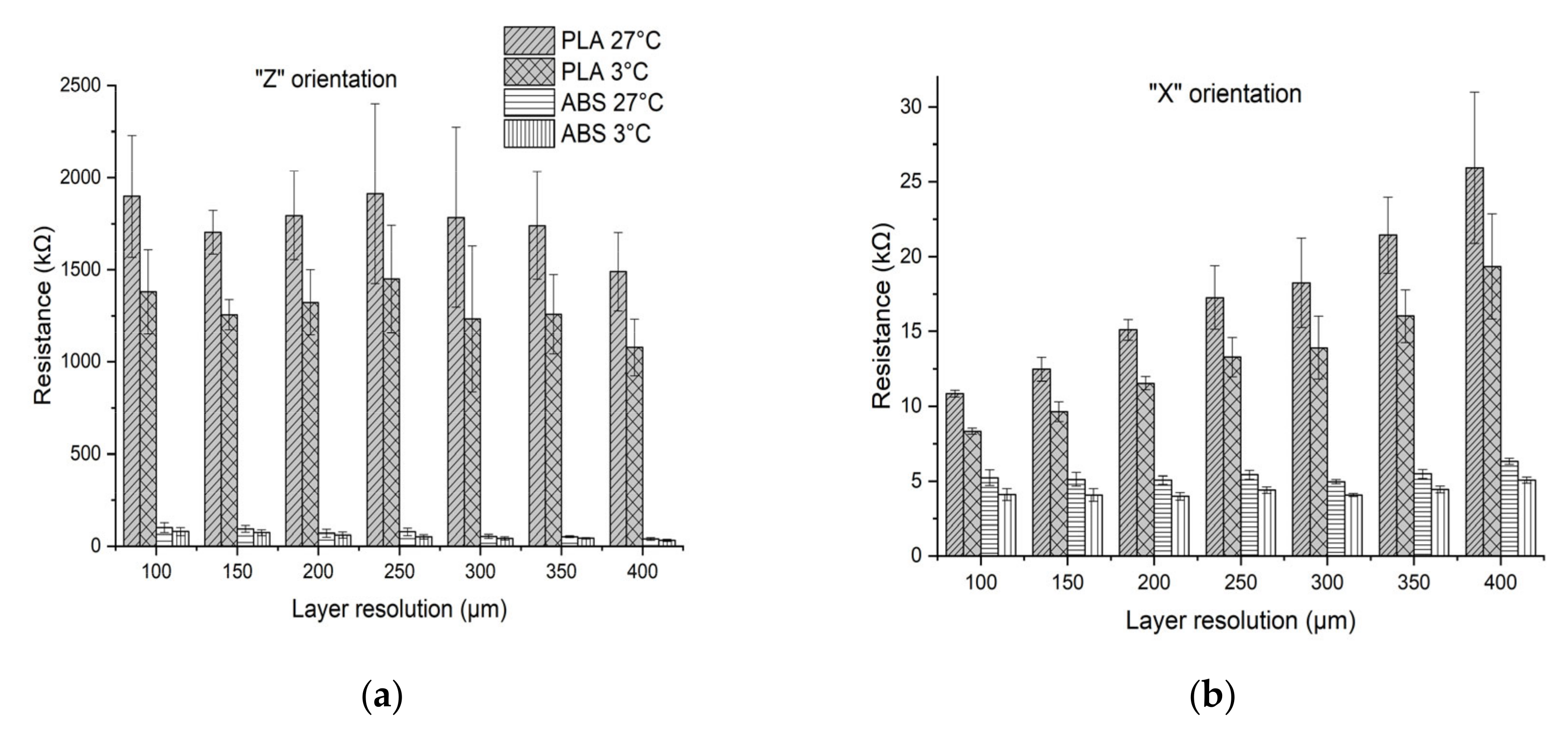
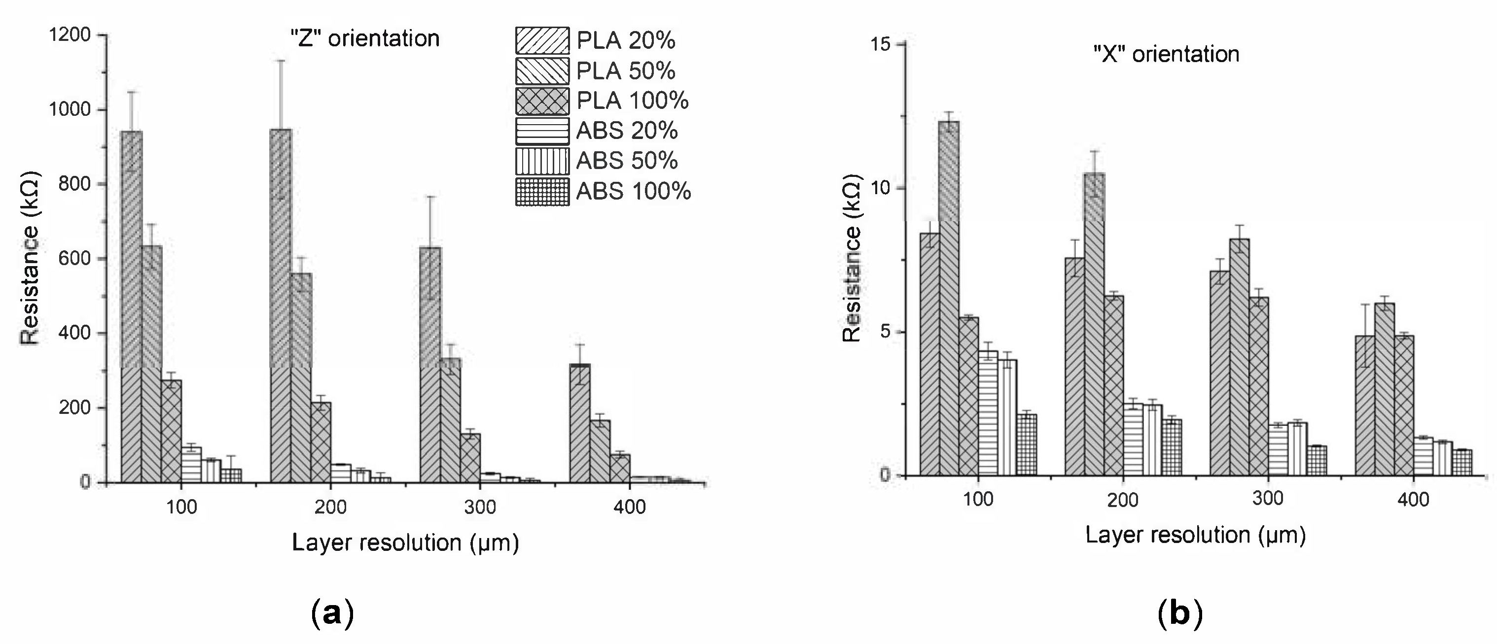
3.1. Electrical Measurements

The results of the electrical measurements show that ESD-PLA and ESD-ABS have significantly different electric characteristics. In addition, they demonstrate that the printing orientation, infill density and layer height are strongly correlated with the electrical resistance of the printed objects (Figure 2). To obtain more detailed results on the effect of the layer height and temperature on the electrical resistance, the measurements were performed with seven different layer resolutions.
It can be seen that the materials had significantly better conductive abilities at a 3 °C ambient temperature, which refers to metal-like electrical behavior. Specimens of PLA based composites had higher resistance values in any kind of printing setting than ESD-ABS. In orientation Z, the layer height did not have a significant impact on resistivity. In orientation X, increasing the layer height increased the resistance in the PLA composite. In orientation X, the resistance value with a 100 micrometer layer height was 10.85 ± 0.22kΩ, while it was 25.93 ± 5.04 kΩ at 400 micrometers, while ESD-ABS showed around a 5 kΩ resistance value on every printing resolution in orientation X; therefore, we could not observe a significant difference.
Infill density is one of the most important printing parameters which can be easily modified using different slicing software. Test specimens printed with 100% infill density had lower resistance values in all specimens (Figure 3). Similarly, to the mechanical parameters, the printing orientation Z can be characterized with remarkable results. In all cases, test bars printed in orientation Z had significantly higher resistance values, up to 100 times higher compared with the X orientation results. The highest resistance was achieved by ESD-PLA with a 200 µm layer height and 20% infill density, resulting in 946.66 ±184.78 kΩ. With the same printing parameters, the resistance value in the case of ESD-ABS was only 49.12 ± 1.86 kΩ. It was also observed that ESD-ABS had lower resistance values compared with the ESD-PLA test specimens created with the same printing parameters. Increasing the layer height at the same infill density, the resistance decreased. Surprisingly, in the case of the measurements with printing orientation X, the ESD-PLA test bars with 50% infill density had higher resistance values than probes with 20% infill density, which does not correlate with the other results. The results show that in the case of conductivity, ESD-ABS performs better, which means this material should be used for creating prototypes for electrical components like wires or sensors.

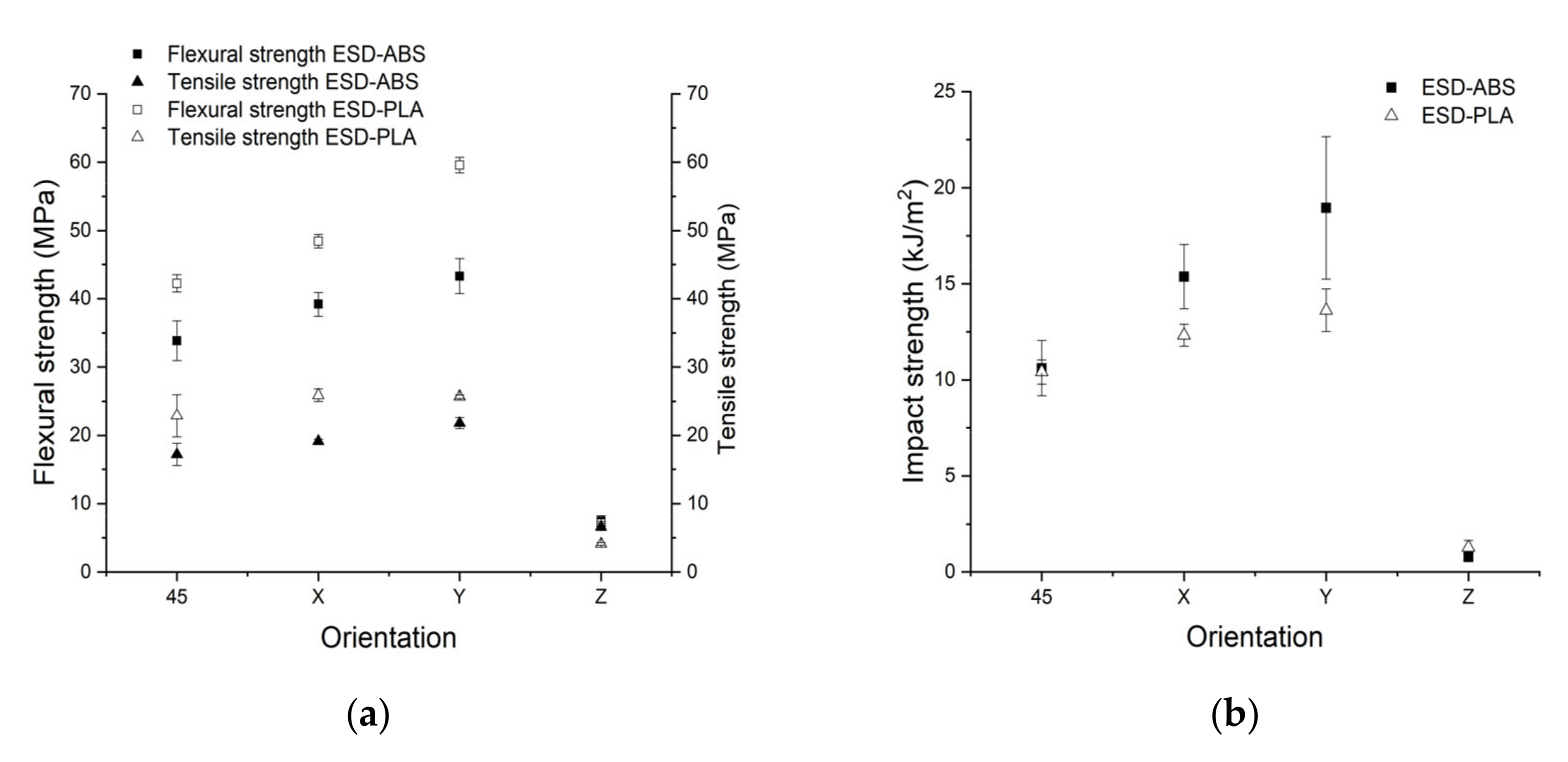
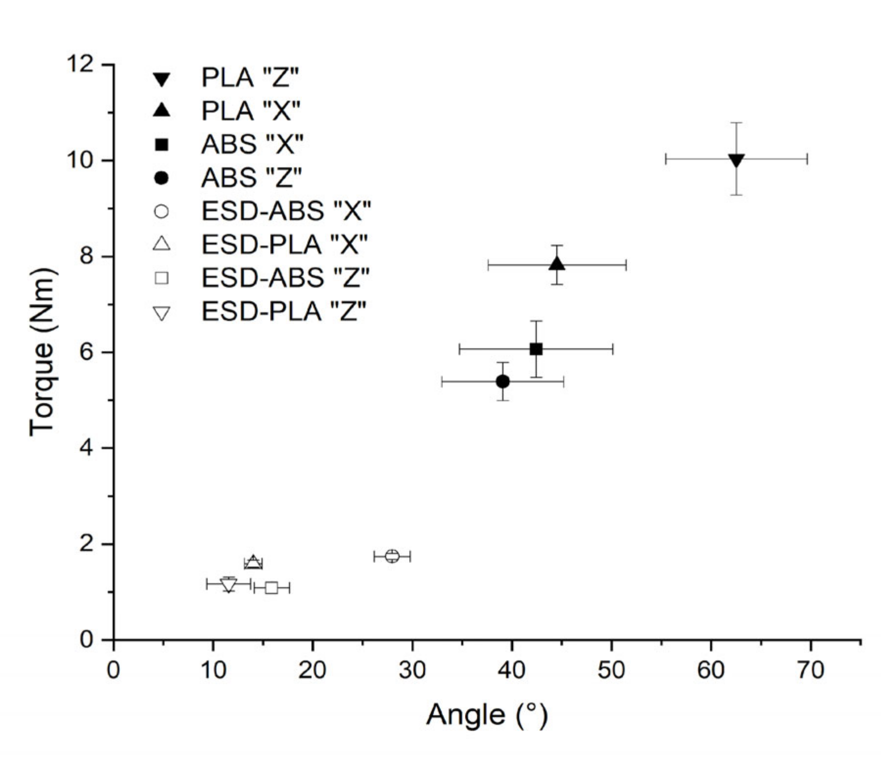
3.2. Mechanical Test Results

The results of the Charpy impact test showed that the Z printing orientation had significantly lower impact strength results than the others (Figure 4). In the case of ESD-PLA, it was 1.27 ±0.37 kJ/m2, and 0.78 ± 0.15 kJ/m2 was measured with ABS test specimens. This observation correlates with our previous experiments [7]. The orientation Y reached the highest values: the ESD-ABS test specimens had an impact strength of 18.95 ± 3 kJ/m2 and the ESD-PLA was 13.62 ±1.1 kJ/m2. It is surprising that the test bars printed with a 45° orientation showed similar results, with 10.61 ±1.44 kJ/m2 and 10.41 ±0.62 kJ/m2; therefore, there was no significant difference between the two materials. The ESD-ABS material can be characterized with a greater stability in the case of dynamic forces, except in the Z orientation. Compared with our previous investigations with neat PLA, we can observe that the carbon filling eventuates the increase of the impact strength [25]. In a previous study, test bars were manufactured with injection molding instead of 3D printing [26]. A neat ABS casted test specimen test resulted in a 11.3 kJ/m2 impact strength value compared with our measurement of 15.37± 1.66 kJ/m2 with X oriented ESD-ABS, which is higher than previously measured neat ABS with a 0.178 mm printing resolution. The results indicate that ESD-ABS can be used when the prosthetic device has to withstand dynamic forces, for example, in the case of manufacturing socket parts.
Tensile strength, flexural strength and Shore D hardness were also measured. Performing tensile tests, orientation Y provided the highest results with 21.79 ± 0.79 MPa for the ESD-ABS, and 25.87 ± 0.89 MPa for the ESD-PLA X orientation test specimens (Figure 4.). As expected, orientation Z showed the lowest results, where no significant difference was measured between the materials. In a previous research work, neat ABS tensile tests were made from the X and Z orientations with a 270 µm layer height [27]. In orientation X, the result was 28.5 MPa; in orientation Z, it was 14.1 MPa. With ESD-ABS, our measured results were 19.14 ± 0.3 MPa in orientation X, while 6.58 ± 0.53 MPa in Z. Compared with the neat material, it has significantly lower results. In the cited article, they used a fully infilled neat PLA specimen with a 200 micrometer layer height printed in orientation X [28]. The measured value was 31.6 MPa, which was higher than our result. The 3-point bending test showed major differences in terms of printing orientation when compared with each other. The highest value was measured in the case of the ESD-ABS in orientation Y with 43.3 ± 2.58 MPa, and the lowest with ESD-PLA in orientation Z, where 7.11 ± 0.28 MPa was measured. This is quite similar to the cited work, where they measured 42.6 MPa for neat ABS [28]. The addition of carbon to PLA slightly decreases the flexural strength compared with neat PLA polymer, and greatly decreases the values of tensile strength [25]. The Shore D measurements did not show significant differences; the values varied between 59.72 ±1.45 and 64.2 ±1 in the case of ESD-ABS, and between 67.1 ±0.77 and 71.66 ±0.45 in the case of ESD-PLA, which is lower than the results of neat materials despite that fillers usually increase the hardness of the materials [29].
Since we have not found a detailed description of torque forces regarding ABS and PLA materials compared in different orientations, we created test specimens as references as well. The results are shown in Figure 5. The end of each measurement was set to the decrease of torque strength by 40%. The maximal torque strength was marked with Tmax and the correlated torsion was marked with φTmax. The results show that ESD-PLA with X orientation had Tmax = 1.59 ± 0.07 Nm and φTmax = 14 ± 0.8° while in the Z direction, it resulted in Tmax = 1.16 ± 0.14 Nm and φTmax = 11.5 ± 2.18°, which significantly differs. It can also be seen that neat PLA and ABS have significantly higher resistance against torque forces; therefore, the carbon, as a filler, decreases the stability. It can also be observed that the orientation dependence is less significant compared to other mechanical tests.

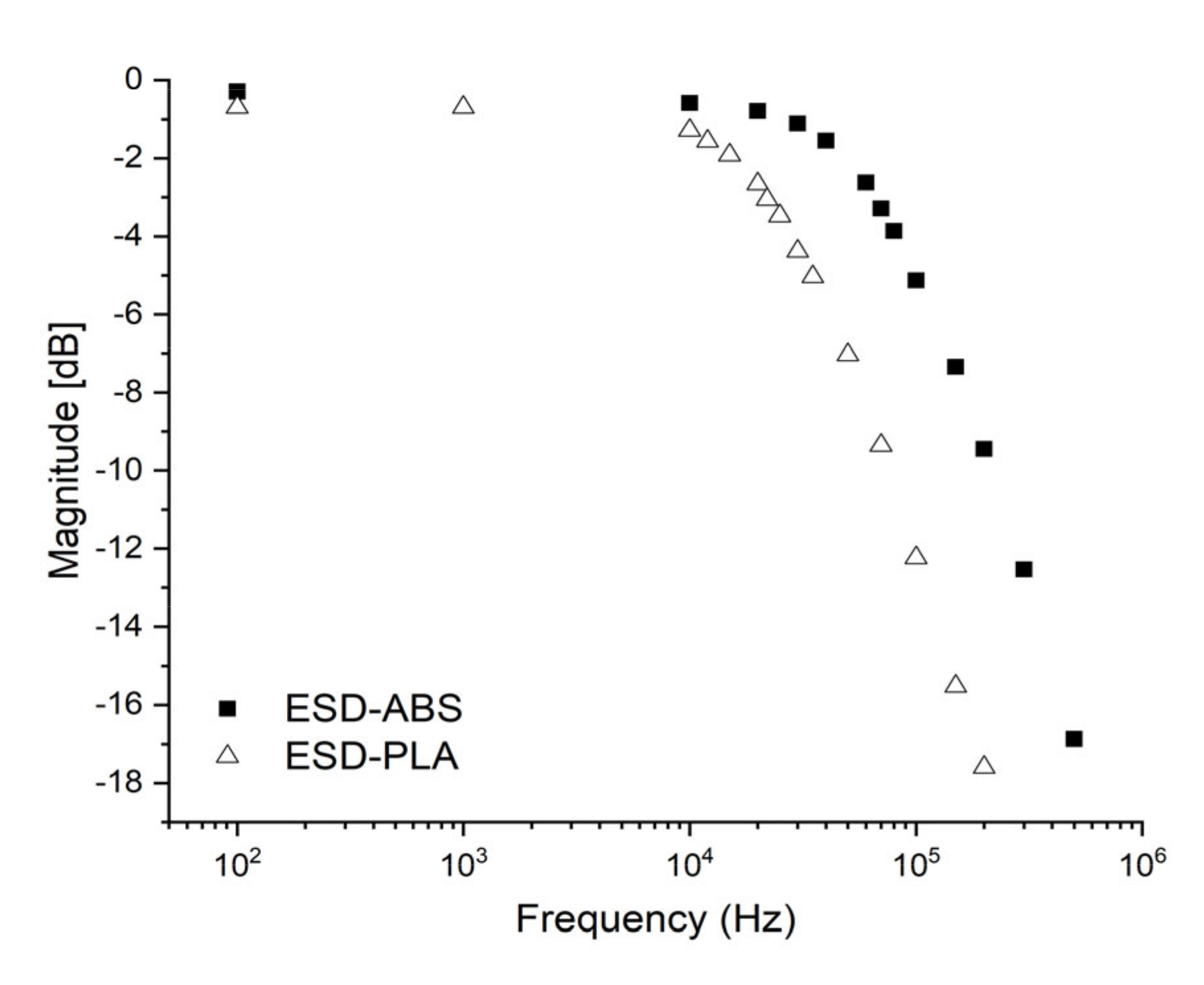
3.3. Results of Signal Transfer Capability

The results of the measurements regarding attenuation are visualized on a Bode diagram (Figure 6). Based on previous results, we selected the test specimens with the smallest electrical resistance, fabricated with a 400 µm layer height. In the case of ESD-PLA, the attenuation stays below – 2 dB until 15 kHz. To examine the signal transfer capability, sinus waves were sent through the test specimens as well. The test was performed at 100 Hz frequency, at cut-off frequency (66.4 kHz) and at 500 kHz. Based on the results, we can state that the materials act as a low-pass filter, which can be promising in EMG (electromyography) signal transfer and processing. This feature can be extremely useful for rapid prototyping of 3D printed, myoelectric prosthetic devices.

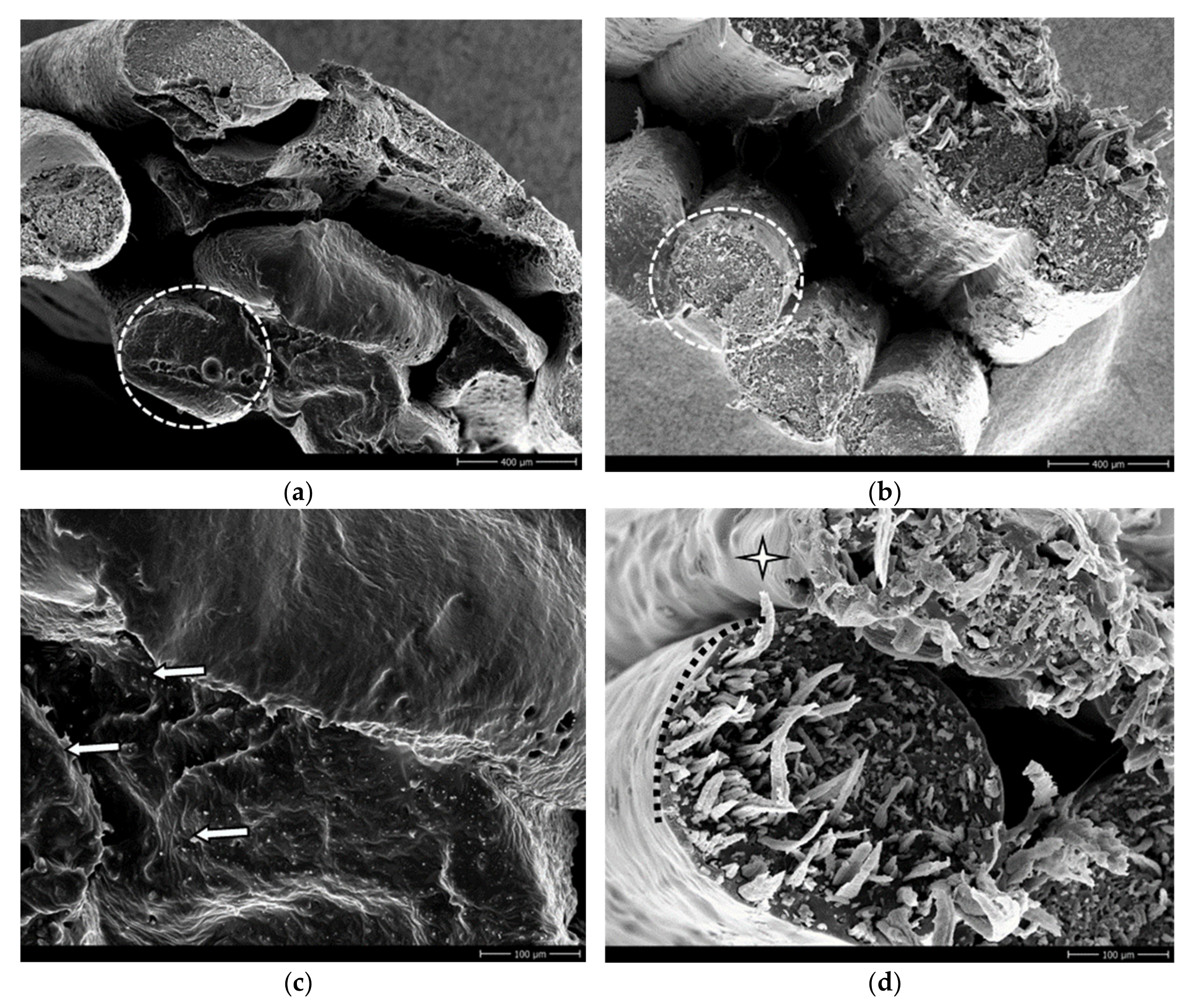
3.4. Structural Analysis

Scanning electron microscopic (SEM) images were also captured from the filaments before the 3D printing and after the manufacturing process of different test specimens. The ESD-ABS filaments have a more dense and homogenous structure, where carbon particles were dissolved smoothly. The ESD-PLA has a different formation: in ESD-PLA, it can be observed that the carbon “threads” run parallel to each other, and the threads fall into smaller, thinner, finer compartments. The length of the threads is variable; they can be changed from 10 micrometers up to 500 micrometers (Figure 7).
These characteristics are clearly visible with 200x magnification. For deeper understanding of the structure of the 3D printed test specimens, we used the ”A” probes as samples. To examine the surface, and after mechanically removing the upper layers, the inner patterns could be revealed. It is clearly shown at a 100 micrometer layer height that the ESD-ABS material has a more structured and ordered synthesis, compared to the ESD-PLA, which is more heterogeneous. This observation was also made with 200x magnification. The test specimens created with a 400 micrometer layer height were ideal to analyze the connections between each layer and the columns building them up. In addition, it was possible to visualize both the dissolved carbon particles embedded in the ESD-ABS and the carbon threads within the ESD-PLA material. With a 60x magnification, it was seen that the columns were more integrated and melted together in the case of the ESD-ABS; this observation correlates with the lower resistance values. With 200X magnification, the homogenous structure and platelet-like broken surface is revealed for the ESD-ABS test specimen, whereas the columns of ESD-PLA are more separated from each other. Figure 8 images with bigger resolution indicate that the carbon threads cause a wire-like structure, where the PLA base component behaves as an insulator.
According to the wire-lie structure, the carbon threads in the ESD-PLA follow the pattern of 3D printing. That explains the higher resistance values in the case of orientation Z test specimens, since the pathway of the extruder has a circular component, which leads to cross-links between the threads, and they become orthogonal to one another. With a magnification of 1700x, the crystalline-like homogenous structure of ABS-carbon composite is detailed, and the particles can be differentiated from one another. In the case of ESD-PLA, the insulator role of the PLA base material is more emphasized. The thickness of the threads could also be determined: they have an average size from 3 to 10 micrometers. In orientation Z, the layers separated in the course and broke, while at other orientations the threads broke.

4. Discussion

Concluding our research, we found an important and practical correspondence between the printing parameters and the electrical and mechanical characteristics in the case of PLA and ABS carbon composites. These observations can play an important role in further upper limb prosthetic developments or in other bionic research projects. Our results revealed that the ESD-PLA and ESD-ABS materials can be used as electrical components like wires or sensors, allowing researchers to extend their rapid prototyping possibilities. Detailed analysis of test specimens A and B revealed that the value of resistance strongly depended on the layer height and infill density. The Z orientation always had significantly higher resistance, since the circular movement of the printing head prevented interconnection between the carbon threads and particles by creating an insulator layer between them. The SEM images proved that these insulator layers covered the conductive components of the materials. The ESD-ABS had better conductivity, caused by the homogenous distribution of carbon particles. It was also observed that the elevation of the layer height did not have a significant impact on the values of the resistivity if the test specimens were small and melted together; therefore, they had a compact and consistent structure printed in the Z orientation, and hence the X orientation had higher resistance with the elevation of the layer height, which can be caused by the printing orientation itself in the case of ESD-PLA. ESD-ABS resistance values seemed to be nearly independent from the layer height in this case. When the printed object had a greater volume, it was clearly observed that the printing infill could improve conductivity, as well as the layer height. This correlation can be explained with the cooling process of the printed material—the greater layer height and infill need more material, which have longer cooling times, that causes a more homogenous structure. One exception could be observed in the case of X orientated ESD-PLA specimens printed with 50% infill density, which had an outstanding resistance value. The explanation of this could be the insufficient rate of interconnection of carbon threads with this infill density, which can be observed on SEM images. As a general observation, it can be stated that ESD-ABS had better electrical conductivity compared to ESD-PLA. In upper limb prosthetic development, some parts should have the ability to rotate and spin, like joints or wrists, and elbow modules. In these cases, mechanical stability is essential. Flexural strength and torque force had higher results in the case of ESD-PLA. This feature can be a game-changer in the case of interconnected, moving parts which need electrical components like wires. In addition, it was proved that the examined materials work like a low-pass filter; therefore, they can be used for EMG signal transmission, which is needlessly important in the case of these devices.

5. Conclusions

Conductive 3D printing materials are necessary for creating complex, functional models and prototypes containing electrical components. Choosing the right printing orientation, infill density and layer height is necessary, since the conductivity has a strong dependence on these parameters. As a result of this study, it is possible to determine the value of resistance using these materials with different printing settings, which can be a reference for further investigations. As an overall conclusion, it was proved that ABS-ESD has more advantageous mechanical and electrical properties compared to ESD-PLA. Our future work aims to examine the possibility to create and examine actual, functional electrical components for our own upper limb prosthetic development project using ESD-ABS and ESD-PLA materials.

Author Contributions

Conceptualization, A.P. and P.M.; methodology, A.S., A.P., H.A. and R.T.; software, A.P., E.M. and M.B.; validation, R.T., A.S. and M.Ny.; formal analysis, P.M. and M.B.; investigation, P.M., H.A and A.P.; resources, P.M.; writing and original draft preparation, A.P., A.S. and P.M.; supervision, P.M.; project administration, E.M. and M.Ny.; funding acquisition, M.Ny. All authors have read and agreed to the published version of the manuscript.

Funding

This research was supported by grants from the New National Excellence Program of the Ministry of Human Capacities ÚNKP-18-3-IV-PTE-153 to PM, the EFOP-3.6.1-16- 2016-00004 and GINOP-2.3.2.-15-2016-00022 grants. The work was supported by the Biomedical Engineering Project (TUDFO/51757-1/2019-ITM) of the University of Pecs.

Acknowledgments

We would like to express our special gratefulness for the members of the University of Pecs, Faculty of Engineering and IT, and also for our colleagues in the Department of Mechanical Engineering.

Conflicts of Interest

The authors declare no conflict of interest.

References

  1. Varma, P.; Stineman, M.G.; Dillingham, T.R. Epidemiology of Limb Loss. Phys. Med. Rehabil. Clin. 2014, 25, 1–8. [Google Scholar] [CrossRef] [PubMed] [Green Version]
  2. Ziegler-Graham, K.; MacKenzie, E.J.; Ephraim, P.L.; Travison, T.G.; Brookmeyer, R. Estimating the Prevalence of Limb Loss in the United States: 2005 to 2050. Arch. Phys. Med. Rehabil. 2008, 89, 422–429. [Google Scholar] [CrossRef] [PubMed]
  3. Watve, S.; Dodd, G.; MacDonald, R.; Stoppard, E.R. Upper limb prosthetic rehabilitation. Orthop. Trauma 2011, 25, 135–142. [Google Scholar] [CrossRef]
  4. Biddiss, E.A.; Chau, T.T. Upper limb prosthesis use and abandonment: A survey of the last 25 years. Prosthet. Orthot. Int. 2007, 31, 236–257. [Google Scholar] [CrossRef]
  5. Demet, K.; Martinet, N.; Guillemin, F.; Paysant, J.; AndrÉ, J.-M. Health related quality of life and related factors in 539 persons with amputation of upper and lower limb. Disabil. Rehabil. 2003, 25, 480–486. [Google Scholar] [CrossRef]
  6. Javaid, M.; Haleem, A. Additive manufacturing applications in medical cases: A literature based review. Alex. J. Med. 2018, 54, 411–422. [Google Scholar] [CrossRef] [Green Version]
  7. Maroti, P.; Varga, P.; Abraham, H.; Falk, G.; Zsebe, T.; Meiszterics, Z.; Mano, S.; Csernatony, Z.; Rendeki, S.; Nyitrai, M. Printing orientation defines anisotropic mechanical properties in additive manufacturing of upper limb prosthetics. Mater. Res. Express 2018, 6, 35403. [Google Scholar] [CrossRef]
  8. Chen, R.K.; Jin, Y.-A.; Wensman, J.; Shih, A. Additive manufacturing of custom orthoses and prostheses—A review. Addit. Manuf. 2016, 12, 77–89. [Google Scholar] [CrossRef] [Green Version]
  9. Ngo, T.D.; Kashani, A.; Imbalzano, G.; Nguyen, K.T.Q.; Hui, D. Additive manufacturing (3D printing): A review of materials, methods, applications and challenges. Compos. Part B Eng. 2018, 143, 172–196. [Google Scholar] [CrossRef]
  10. Kate, J.T.; Smit, G.; Breedveld, P. 3D-printed upper limb prostheses: A review. Disabil. Rehabil. Assist. Technol. 2017, 12, 300–314. [Google Scholar] [CrossRef]
  11. Vujaklija, I.; Farina, D. 3D printed upper limb prosthetics. Expert Rev. Med Devices 2018, 15, 505–512. [Google Scholar] [CrossRef] [PubMed]
  12. Macdonald, E.; Salas, R.; Espalin, D.; Perez, M.; Aguilera, E.; Muse, D.; Wicker, R.B. 3D Printing for the Rapid Prototyping of Structural Electronics. IEEE Access 2014, 2, 234–242. [Google Scholar] [CrossRef]
  13. Valentine, A.D.; Busbee, T.A.; Boley, J.W.; Raney, J.R.; Chortos, A.; Kotikian, A.; Berrigan, J.D.; Durstock, M.F.; Lewis, J.A. Hybrid 3D Printing of Soft Electronics. Adv. Mater. 2017, 29, 1703817. [Google Scholar] [CrossRef] [PubMed]
  14. Nebojsa, P.D.D.; Jaksic, I. Characterization of resistors created by fused filament fabrication using electrically-conductive filament. Procedia Manuf. 2018, 17, 37–44. [Google Scholar]
  15. Leigh, S.J.; Bradley, R.J.; Purssell, C.P.; Billson, D.R.; Hutchins, D.A. A Simple, Low-Cost Conductive Composite Material for 3D Printing of Electronic Sensors. PLoS ONE 2012. [CrossRef]
  16. Czyżewskia, P.B.J.; Gawełb, K.; Meisnerc, J. Rapid prototyping of electrically conductive components using 3D printing technology. J. Mater. Process. Technol. 2009, 209, 5281–5285. [Google Scholar] [CrossRef]
  17. Jakus, A.E.; Secor, E.B.; Rutz, A.L.; Jordan, S.W.; Hersam, M.C.; Shah, R.N. Three-Dimensional Printing of High-Content Graphene Scaffolds for Electronic and Biomedical Applications. ACS Nano 2015, 4636–4648. [Google Scholar] [CrossRef]
  18. Marasso, S.L.; Cocuzza, M.; Bertana, V.; Perrucci, F.; Tommasi, A.; Ferrero, S.; Scaltrito, L.; Pirri, C.F. PLA conductive filament for 3D printed smart sensing applications. Rapid Protoyping J. 2018, 24, 739–743. [Google Scholar] [CrossRef]
  19. Gao, H.; Meisel, N.A. Exploring the Manufacturability and Resistivity of Conductive Filament Used in Material Extrusion Additive Manufacturing. In Proceedings of the 28th Annual InternationalSolid Freeform Fabrication Symposium, Austin, TX, USA, 7–9 August 2017. [Google Scholar]
  20. Desai, P.D. Characterization and Applications of Electrically-Conductive Filament in 3D Printing. Ph.D. Thesis, Colorado State University-Pueblo, Pueblo, CO, USA, 2016. [Google Scholar]
  21. Rodriguez-Panes, A.; Claver, J.; Camacho, A.M. The Influence of Manufacturing Parameters on the Mechanical Behaviour of PLA and ABS Pieces Manufactured by FDM: A Comparative Analysis. Materials 2018, 11, 1333. [Google Scholar] [CrossRef] [Green Version]
  22. Cuan-Urquizo, E.; Barocio, E.; Tejada-Ortigoza, V.; Pipes, R.B.; Rodriguez, C.A.; Roman-Flores, A. Characterization of the Mechanical Properties of FFF Structures and Materials: A Review on the Experimental, Computational and Theoretical Approaches. Materials 2019, 12, 895. [Google Scholar] [CrossRef] [Green Version]
  23. Keleş, Ö.; Blevins, C.W.; Bowman, K.J. Effect of build orientation on the mechanical reliability of 3D printed ABS. Rapid Prototyp. J. 2016, 23. [Google Scholar] [CrossRef]
  24. Wang, K.; Li, S.; Rao, Y.; Wu, Y.; Peng, Y.; Yao, S.; Zhang, H.; Ahzi, S. Flexure behaviors of ABS-based composites containing carbon and Kevlar fibers by material extrusion 3D printing. Polymers 2019, 11, 1878. [Google Scholar] [CrossRef] [PubMed] [Green Version]
  25. Varga, P.; Lorinczy, D.; Tóth, L.; Pentek, A.; Nyitrai, M.; Maroti, P. Novel PLA-CaCO3 composites in additive manufacturing of upper limb casts and orthotics—A feasibility study. Mater. Res. Express 2019, 6. [Google Scholar] [CrossRef]
  26. Liu, X.; Bertilsson, H. Recycling of ABS and ABS/PC blends. J. Appl. Polym. Sci. 1999, 74, 510–515. [Google Scholar] [CrossRef]
  27. Perez, A.R.T.; Roberson, D.A.; Wicker, R.B. Fracture Surface Analysis of 3D-Printed Tensile Specimens of Novel ABS-Based Materials. J. Fail. Anal. Prev. 2014, 14, 343–353. [Google Scholar] [CrossRef]
  28. Weng, Z.; Wang, J.; Senthil, T.; Wu, L. Mechanical and thermal properties of ABS/montmorillonite nanocomposites for fused deposition modeling 3D printing. Mater. Des. 2016, 102, 276–283. [Google Scholar] [CrossRef]
  29. Vian, W.D.; Denton, N.L. Hardness Comparison of Polymer Specimens Produced with Different Processes; ASEE IL-IN Section Conference 3; Purdue University: West Lafayette, IN, USA, 2018. [Google Scholar] [CrossRef]
Figure 1. Printing orientations of the different test specimens in the CraftWare™ software—screenshots. (a) Test specimens to determine the effect of the layer height on resistance—specimen “A.” (b) Test specimens for measuring the effect of the infill density on resistance—specimen “B.” (c) Test specimen for signal transfer capability—specimen “C.” (d) Test specimens for the tensile test strength. (e) Test specimens for the torque strength test.
Crystals 10 00398 g001
Figure 2. The effect of the layer height and temperature on electrical resistance. The test bars indicate the mean with the standard deviation of the measured resistance values. On the left (a), the results of the Z printing orientation, and on the right (b), the results of the X printing orientation are demonstrated.
Crystals 10 00398 g002
Figure 3. The effect of infill density on electrical resistance. The test bars indicate the average resistance values with the standard deviation. On the left (a), the results of the Z printing orientation, and on the right (b), the results of the X printing orientation are demonstrated.
Crystals 10 00398 g003
Figure 4. The results of dynamical and static mechanical testing. The graph on the left (a) demonstrates the results of tensile test strength and the 3-point bending test; (b) indicates the results of the Charpy Impact test in each printing orientation. Mean values with the standard deviation are demonstrated.
Crystals 10 00398 g004
Figure 5. The results of torque strength tests and torsion angle of the test specimens manufactured with different materials. Mean values are demonstrated with the standard deviation.
Crystals 10 00398 g005
Figure 6. On the Bode diagram, the attenuation values can be observed. The length of test specimens was 100 mm, printed with a 400 µm layer height.
Crystals 10 00398 g006
Figure 7. Scanning electron microscopy (SEM) images. Image (a) shows the cross-section of an ESD-ABS filament. The white arrows indicate the carbon particles, and the white star shows the surface of the filament. Image (b) has been taken from the cross section of ESD-PLA filaments, where the carbon threads are marked with white arrows, and a bigger piece of it with a white star. The discursive white lines indicate the orientation of the threads in the filament. Image (c) has been taken after printing with 100 micrometers. In direction X with ABS material, while (d) shows ESD-PLA with the same printing parameters. The brackets demonstrate 1 layer (size: 100 micrometers). Magnification 200x.
Crystals 10 00398 g007aCrystals 10 00398 g007b
Figure 8. Scanning electron microscopy (SEM) images. Image (a) shows the printed structure of the ESD-ABS test specimen and (b) shows ESD-PLA with 200x magnification, where the printed columns are marked with a discursive circle. On image (c), the arrows indicate the carbon particles in the ESD-ABS, and in (d), the white star shows the side of a column in printed ESD-PLA and the dashed black curve indicates the margin of it. The images were taken with 1700x magnification.
Crystals 10 00398 g008

