Next Article in Journal
Response Improvement of Liquid Crystal-Loaded NRD Waveguide Type Terahertz Variable Phase Shifter
Previous Article in Journal
Gypsum Crystallization during Reverse Osmosis Desalination of Water with High Sulfate Content in Presence of a Novel Fluorescent-Tagged Polyacrylate
Previous Article in Special Issue
Electrochemical Characterization of CVD-Grown Graphene for Designing Electrode/Biomolecule Interfaces
 
 
Retraction published on 10 July 2020, see Crystals 2020, 10(7), 597.
Article

Artificial Intelligence Algorithm Enabled Industrial-Scale Graphene Characterization

by
Wei Sun Leong
1,*,
Giuseppe Arrabito
2 and
Giuseppe Prestopino
3
1
Department of Materials Science and Engineering, National University of Singapore, Singapore 117575, Singapore
2
Dipartimento di Fisica e Chimica - Emilio Segrè, Università degli Studi di Palermo, Ed.17, V.le delle Scienze, 90128 Palermo, Italy
3
Dipartimento di Ingegneria Industriale, Università di Roma ‘Tor Vergata’, Via del Politecnico 1, I-00133 Roma, Italy
*
Author to whom correspondence should be addressed.
Crystals 2020, 10(4), 308; https://doi.org/10.3390/cryst10040308
Submission received: 1 April 2020 / Revised: 11 April 2020 / Accepted: 14 April 2020 / Published: 16 April 2020
(This article belongs to the Special Issue 2D Materials: From Structures to Functions)

Abstract

:
No characterization method is available to quickly perform quality inspection of 2D materials produced on an industrial scale. This hinders the adoption of 2D materials for product manufacturing in many industries. Here, we report an artificial-intelligence-assisted Raman analysis to quickly probe the quality of centimeter-large graphene samples in a non-destructive manner. Chemical vapor deposition of graphene is devised in this work such that two types of samples were obtained: layer-plus-islands and layer-by-layer graphene films, at centimeter scales. Using these samples, we implemented and integrated an unsupervised learning algorithm with an automated Raman spectroscopy to precisely cluster 20,250 and 18,000 Raman spectra collected from layer-plus-islands and layer-by-layer graphene films, respectively, into five and two clusters. Each cluster represents graphene patches with different layer numbers and stacking orders. For instance, the two clusters detected in layer-by-layer graphene films represent monolayer and bilayer graphene based on their Raman fingerprints. Our intelligent Raman analysis is fully automated, with no human operation involved, is highly reliable (99.95% accuracy), and can be generalized to other 2D materials, paving the way towards industrialization of 2D materials for various applications in the future.

1. Introduction

Graphene and related two-dimensional (2D) materials are a family of exciting materials, which are as small as one to three atoms in vertical direction, but extremely large in horizontal space [1,2,3,4,5]. These systems have attracted significant attention for nanoelectronics and optoelectronics [6,7,8,9,10], non-von Neumann architecture computing [11,12], hybrid flexible and stretchable electronics [13,14,15], and many other applications. As a consequence of their extremely high market value, 2D materials are very attractive to many industries. For example, Samsung and Huawei have adopted graphene for displays and batteries, respectively. Nevertheless, most industries are still hesitant to adopt 2D materials in their products, due to the lack of reliable characterization methods to accurately probe the quality of industrial-scale 2D materials. For this reason, the development of methods that can rapidly inspect large-area 2D materials that allow manufacturers to determine their suitability for product manufacturing, become tremendously important. To address this research gap, a rapid, intelligent characterization method to analyze the quality of centimeter-scale 2D material films would be highly beneficial.
In recent years, artificial intelligence (AI) tools such as machine-learning paradigms have been proposed to improve the yield of nanomaterials characterization methods [16,17]. For 2D material research, it has been reported that machine learning algorithms integrated with optical microscopy can be used to quantify thickness, impurities, and stacking order in mechanically exfoliated graphene and transition metal chalcogenides [18], and even automatically locate them [19]. Machine learning algorithms have also been used to identify atomic species and defects in transitioning metal chalcogenides by processing high-resolution scanning transmission electron microscopy images [20]. Combining atomic force microscopy topography and friction force microscopy characterization data, Cellini and coworkers constructed an AI clustering tool to identify domains in epitaxial and exfoliated graphene films [21].
Here, we report an AI tool to quantify the defects in chemical vapor deposition (CVD) graphene films, by classifying the Raman spectroscopy data. Among many graphene synthesis routes, CVD is chosen in this work due to its high-quality, low-cost, and scalability to mass production for industrial applications [22,23,24]. Furthermore, among many characterization methods, Raman analysis is chosen in this work because it is a popular, versatile, high-throughput, very low invasive, and non-destructive methodology for the characterization of graphene [25,26,27,28]. Probing graphene quality by Raman spectroscopy is now a straightforward and automated process, applicable at both laboratory and mass-production scales, which involves simple sample preparation, a laser-based microscopy, and ambient operation. Raman spectroscopy has been widely used to probe graphene and understand its layer number and stacking order [27,29], defect level [30,31], and the strain-doping relationship [32,33]. Image processing algorithms integrated with Raman spectra calibration have also been demonstrated to automatically identify the thickness of mechanically exfoliated graphene from their high-resolution optical images [34]. An algorithm that can detect the thickness of mechanically exfoliated graphene based on its Raman spectra has also been reported [35]. Furthermore, a combination of carbon-isotope-labeling and Raman imaging can be used to visualize the time evolution of graphene domain growth [36].

2. Materials and Methods

A Cu foil purchased from Alfa Aesar (#46365) with 25 μm thickness and 99.8% purity was used as the growth substrate to obtain the centimeter-scale graphene samples employed in this work. Prior to growth, a 10 × 2 cm2 Cu substrate was first cleaned by sonicating in a nickel etchant to remove surface contaminations. We refer to this substrate as “bare Cu”. In order to study graphene samples with different quality, we performed an additional oxidative pre-treatment on another 10 × 2 cm2 Cu substrate, which is named as “treated Cu”. Specifically, the substrate was annealed in ambient atmosphere at 130 °C for 3 h, after the Ni etchant treatment.
After pretreatments, both Cu substrates were folded into a pocket structure, similar to previous work [37], and loaded separately into a low-pressure chemical vapor deposition (LPCVD) system. The temperature of the LPCVD system was then ramped up to 1050 °C in 30 min (50 mTorr). In the next 30 min, the LPCVD system was maintained at 1050 °C. Then, 50 sccm of H2 gas was introduced into the system, and 1 min later, 1 sccm of CH4 was added to activate the graphene deposition. The system was maintained under the same conditions for one hour.
It should be noted that graphene with a different thickness was synthesized at the exterior side of the Cu pocket, using the LPCVD approach described above. In order to transfer the exterior graphene from the 10 × 2 cm2 growth substrate to a destination substrate for characterization, the Cu pocket was carefully cut, with extra care given to its exterior side.
All graphene samples investigated in this work were transferred on Si/SiO2 substrates with the help of polymethylmethacrylate (PMMA) support layers. A 300 nm thick layer of PMMA 950 A5 (Microchem Inc., Westborough, MA, USA) was first spun-coated on the graphene/Cu sample, followed by one hour of 80 °C oven baking. To remove the Cu growth substrate, the sample was then floated on top of Cu etchant for half an hour, after which the sample was rinsed with deionized water at least thrice. For these steps of sample rinsing, a flat scoop (i.e., Si wafer or glass slide) was used to ship the sample from one beaker of deionized water to another, and an external force (i.e., tweezers) was required to drive the sample from the liquid surface to the flat scoop, until the sample was free of Cu etchant residues. Finally, the destination substrate (i.e., Si/SiO2 substrate) was used to fish the graphene film. In order to expedite sample drying, the sample was initially blown dry with nitrogen flow, followed by 8 h of oven baking at 80 °C. To remove the sacrificial PMMA support layer, the sample was then soaked in acetone for 6 h, rinsed with isopropyl alcohol, and finally blown dry with nitrogen. A schematic representation of the LPCVD of graphene on the two different types of Cu substrates, and optical images of the respective graphene samples transferred on SiO2/Si substrates, are shown in Figure 1.
A 532 nm excitation laser (Ulm, Germany) with a 100 × objective lens (WITec Alpha 300 micro-Raman imaging system) and a laser spot size of ∼320 nm was used for the acquisition of all Raman spectra and maps reported in this work. The acquisition time per spectra was set to 500 milliseconds and the laser power measured at the sample was always kept below 80 µW.
For the artificial intelligence analysis, we applied k-means clustering to separate unlabeled data samples into k groups with squared Euclidean distance as a dissimilarity measure between two data points. A similar algorithm was shown to be effective in clustering Raman spectra data to understand the strain-doping relationship in epitaxially grown graphene [38]. In our k-means algorithm, all data points were clustered based on similarity. In other words, dissimilarity was minimized within each cluster, whereas differences between clusters were maximized. Specifically, the dissimilarity between a data point and a cluster center is the distance from the data point to the cluster center. Therefore, the dissimilarity within a cluster will be the sum over the distances between data points in that cluster and the cluster center. The summation of all cluster dissimilarities is called global dissimilarity, which can be calculated by iterating over each cluster, each data point within the cluster, and each feature of the data point:
k = 1 K n : X n S k d = 1 D ( x n , d μ k , d   ) 2
where k is the number of clusters, K is the total number of clusters, n is the number of data points, d is the number of features, D is the total number of features, xn,d is a new data point, and μ k , d   is the mean of the cluster. Since the cluster centers of Raman data are not known in advance, we initialized them with a set of values randomly picked from the existing data points. Subsequently, two steps were performed alternately: (i) assign each data point to the cluster with the closest cluster center, and (ii) update the cluster center to be the mean of all the data points in its cluster. The iteration of these two steps was continued until a convergence point was found. It is worth noting that the k-means function from the Scikit-learn package [39] was used in this work.

3. Results and Discussion

Using the same growth recipe, random growth of tri-layer graphene (3LG) islands, as well as inevitable nucleation of thicker layers, were observed on the bare Cu substrate, while only monolayer graphene (1LG) and bilayer graphene (2LG) regions were observed on the treated Cu (see Figure 1 and Figure 2A). Indeed, the treated Cu case is an idealistic situation where layer-by-layer, Frank-van der Merwe growth mode was achieved, and islands of thicker graphene impurities were suppressed.
With the help of microscopy analysis, a statistical method was developed to quantify the multilayer impurities in both graphene samples. For such analysis, we randomly acquired 10 microscopy images, with sizes of at most 40 × 40 µm2, from graphene samples grown on both bare and treated Cu, which were then transferred onto separate Si/SiO2 substrates. Each image was converted into grayscale, and the corresponding pixel counts (5,002,624 pixels for each image) were plotted. In Figure 2B, the histograms from typical graphene samples grown on bare and treated Cu substrates were plotted, which respectively show four peaks (1LG, 2LG, 3LG and 4LG), and two peaks (1LG and 2LG). In order to systematically label graphene regions with different layer numbers, we assigned a range of gray levels to each histogram peak, and converted the corresponding pixels into red (Figure 2C). Upon layer labeling in each microscopy image, we estimated the occurrence probability of 1LG, 2LG, and multilayer graphene (MLG), the latter representing 3LG, 4LG, and above, by extracting the ratio of pixel counts (Figure 2D). The occurrence probability of 2LG is less than half (46.20 ± 14.22%) for graphene samples grown with “bare Cu”, while that of “treated Cu” is close to 100% (99.32 ± 0.34%).
Figure 3 shows Raman analysis for both types of graphene samples whose respective optical images are displayed in Figure 3A and Figure 3D. Figure 3B plots the Raman spectra of graphene grown on treated Cu, taken from four typical spots. Spot 1 exhibits the typical 1LG Raman signatures: the positions of G and 2D bands ( ω G and ω 2 D ) are located at 1582 and 2670 cm−1, respectively; the intensity ratio of 2D to G band (I2D/IG) is ~2; and the 2D full width at half maximum ( Γ 2 D ) is 34 cm−1. On the other hand, spots 2, 3, and 4 exhibit almost identical Raman spectra: ω G = 1580 cm−1, ω 2 D = 2680 cm−1, I2D/IG = 1, and Γ 2 D = 58 cm−1. These features all can be identified as quasi-AB-stacked 2LG; that is, twisting angles between two graphene layers are very small (θ = 0 to 5°) [40,41]. In Figure 3C, we collected a total of 18,000 Raman spectra across a selected area of 30 × 24 µm2, which consisted of two 2LG domains that merged and were encompassed by 1LG region. We found the I2D/IG ratio to be constant at ~1.0 over the two merging domains of 2LG, suggesting that both 2LG domains are quasi-AB-stacked 2LG with similar stacking orders.
As for the graphene sample grown on bare Cu, Raman spectra taken from the four spots indicated in Figure 3D all had different ω G , ω 2 D , I2D/IG, and Γ 2 D (Figure 3E). Based on the Raman spectra characteristics, spots 1 and 4 were found to be 1LG and 3LG, respectively, while spots 2 and 3 were found to be 2LG regions since they had the same optical contrast under optical microscope, and their optical contrast is intermediate between that of 1LG and that of 3LG (see Figure 3D). Spot 2 is quasi-AB-stacked 2LG with a small-twisting-angle (I2D/IG = 0.77 and Γ 2 D = 62 cm−1), whereas spot 3 is a larger-twisting-angle 2LG (I2D/IG = 2.3 and Γ 2 D = 37 cm−1). Indeed, the variation of twisting angles in the graphene sample grown on bare Cu is large, unlike those of the treated Cu. In Figure 3F, we collected a total of 20,250 Raman spectra from a typical graphene sample grown on bare Cu, over an area that consists of 1LG, 2LG, and 3LG, and MLG. Surprisingly, the 2LG region that appeared to be uniform under an optical microscope shows at least two distinct divisions in the Raman map of I2D/IG (Figure 3F), indicating that the 2LG region was made of at least two domains with very different stacking orders (i.e., twisting angles).
Although Raman mapping is a useful tool for researchers to effectively estimate the quality of a graphene sample [25,26,27,28,29,30,31,32,33], it is not an efficient methodology for industrial manufacturers who need the quality inspection of a centimeter-scale graphene film to be completed within a minute for high-throughput mass production. For example, it took more than an hour for an experienced graphene researcher to collect sufficient Raman spectra and plot the intensity map shown in Figure 3F, which is only across an area as small as 30 × 27 µm2. The steps involved: (1) fine-tuning parameters in Raman spectroscopy, (2) analyzing each Raman spectrum with mathematical software to extract useful information, and finally (3) plotting multiple data maps to visualize the pattern of Raman data throughout the spectra collected region and interpreting them. To optimize the image resolution of a Raman map, graphene experts are required to operate the Raman spectroscopy because there are many technical details involved. For example, locations of all Raman spectra must be close enough to avoid pixelation because each spot represents an image pixel. Furthermore, parameter tunings in Step 1 must be repeated multiple times to make sure the intensity values of collected Raman spectra are large enough for mathematical calculations in Step 2 later. Experts are also needed to extract and interpret useful information from the Raman spectra. A critical challenge that experts faced in constructing a larger, millimeter-scale Raman map is the significant change of Raman intensity that inevitably happens whenever there is a small vibration or ambient noise.
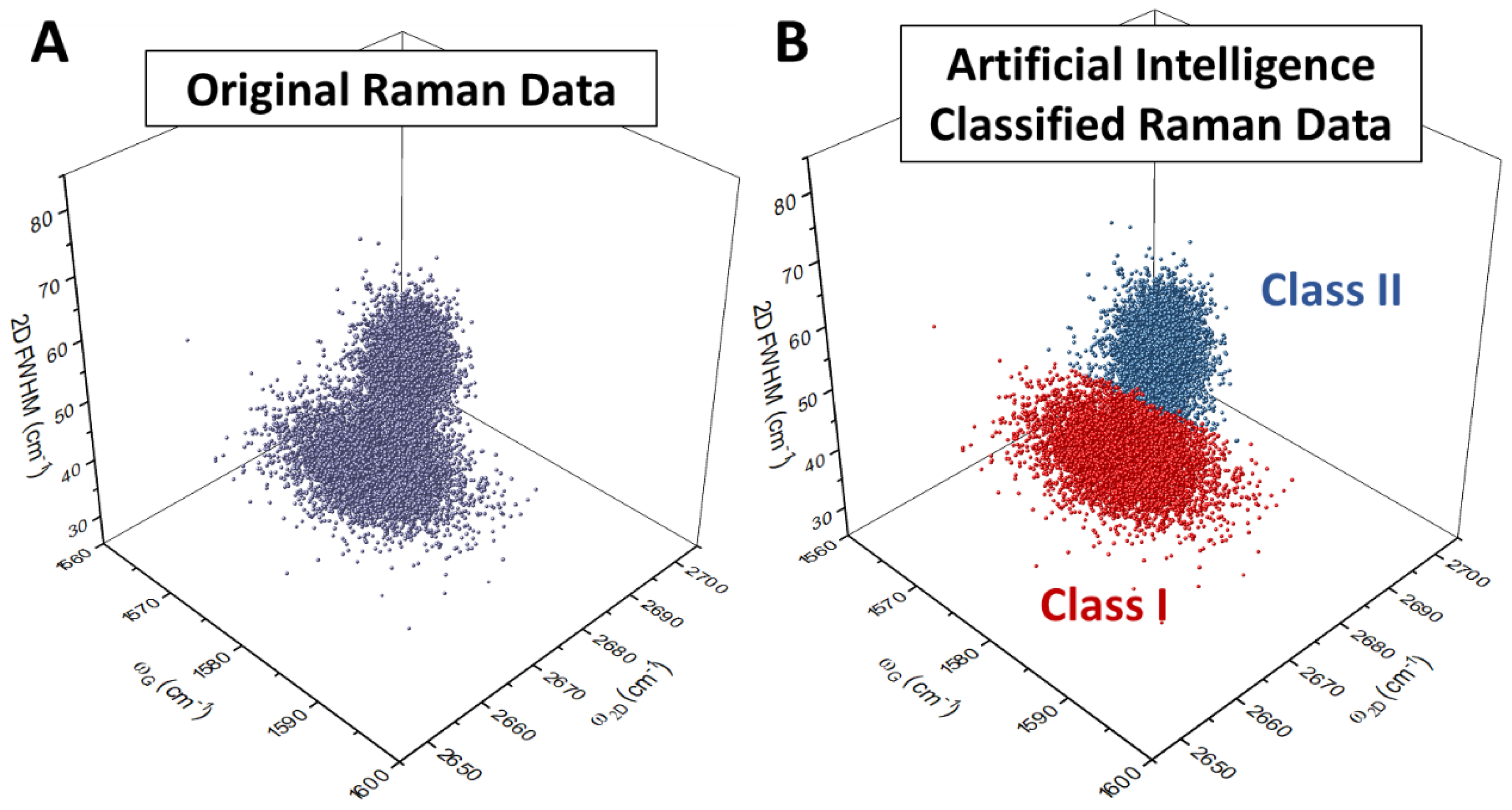
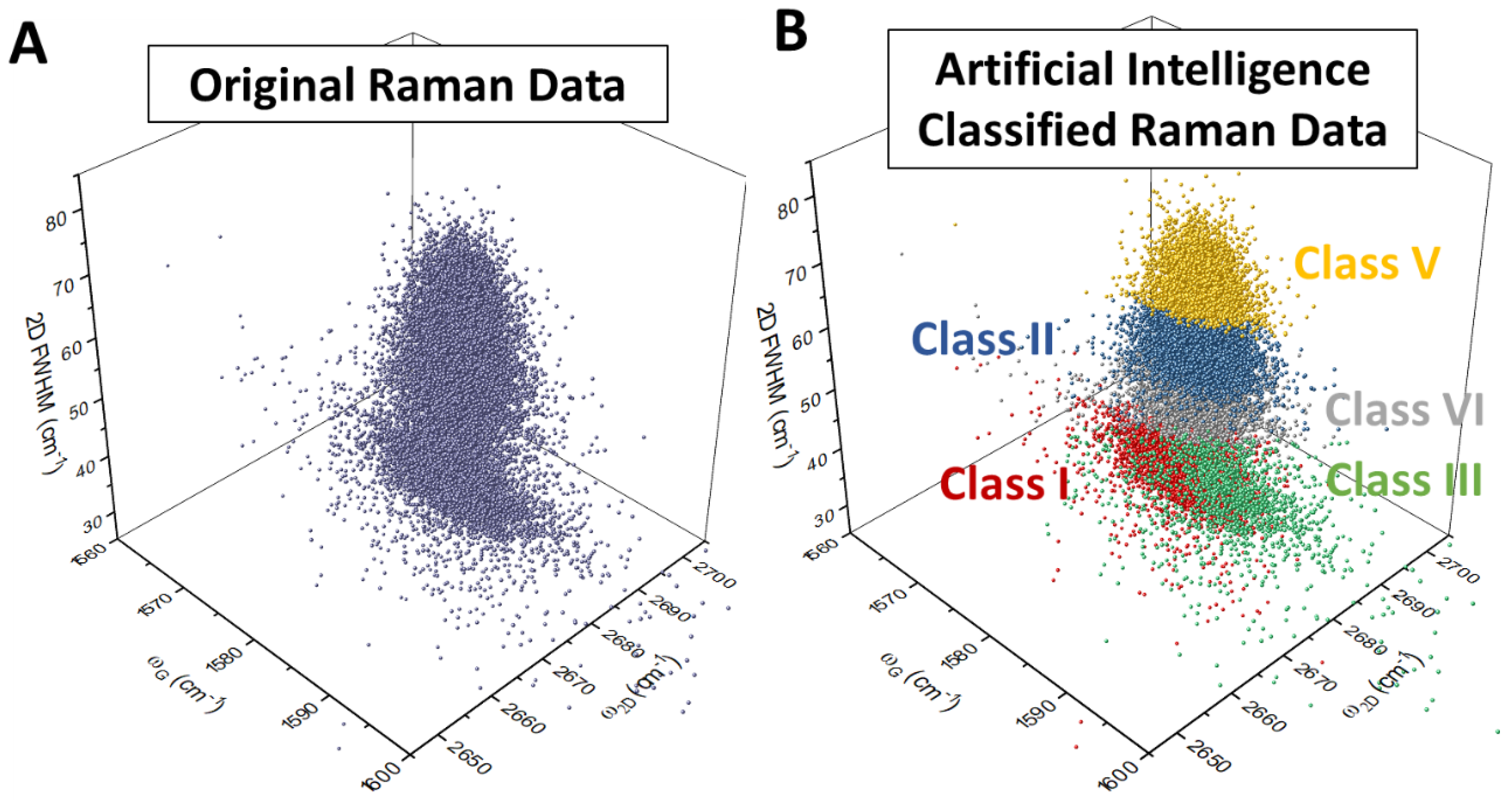
Instead of Raman mapping, we demonstrated that the same groups of collected Raman spectra can be analyzed using an artificial intelligence (AI) tool. To use the AI tool in analyzing Raman data, end users only have to load Raman spectra collected from graphene samples as inputs, and the analysis of Raman data will run automatically. For demonstration purposes, we loaded the 18,000 Raman spectra collected for Figure 3C to an AI tool equipped with a simple and fast unsupervised learning approach, based on the k-means algorithm, which measures dissimilarity between two data points using square Euclidean distance. In the proposed artificial-intelligence-assisted Raman data classification, only three parameters (namely, ω G , ω 2 D , and Γ 2 D ) were extracted from each Raman spectrum, and they were selected as clustering features (Figure 4A). The developed k-means algorithm clustered all 18,000 Raman spectra into two classes (Figure 4B), without the need of complicated software analysis. By reading the mean value ( ω G ¯ , ω 2 D ¯ , Γ 2 D ¯ ) of each class, we identified Class I and II as the Raman data attributed to 1LG and quasi-AB-stacked 2LG, respectively. The same k-means algorithm was also used to cluster the more complicated layer-plus-island graphene film. As can be seen in Figure 5, the k-means algorithm is able to classify all 20,250 Raman spectra collected for Figure 3F into five classes. By reading the mean value ( ω G ¯ , ω 2 D ¯ , Γ 2 D ¯ ) of each cluster, we identified Class I to V as the Raman data attributed to 1LG, quasi-AB-stacked 2LG, larger-twisting-angle 2LG, 3LG, and MLG, respectively. By manually comparing the assigned class number of each Raman spectra with the Raman mapping results, we found that the accuracy of our AI-integrated Raman analysis results are at least 99.95%, much higher than that of conventional algorithms with only 90% satisfactory results [35]. This difference can be attributed to the fact that our algorithm is not based on the fitting of the 2D band as it is in the study by Caridad et al. [35]. It is simple to distinguish monolayer graphene by fitting the 2D band with one Lorentzian peak, but the situation becomes complicated for the case of multilayers, since the electronic structure and the phonon scattering processes are more complex, affecting the peak shape which becomes less symmetric and making an exact fit with multiple components a challenging task [42,43]. For this reason, a straightforward approach that tackles this issue is needed, especially since a more basic and automatable classification of graphene quality, and our AI-integrated Raman analysis, has addressed this issue.
We note that our AI-assisted Raman analysis is essentially suitable for industrial purposes because the required expertise and machine supervision are very minimal. First, our AI-assisted Raman analysis does not rely on image resolution. Therefore, repeated fine-tuning of Raman spectroscopy parameters is not required, and locations of the collected Raman spectra are flexible. Our analysis results are also straightforward where each Raman data was labeled with a class number. Instead of complicated software that requires intensive trainings, end users can easily understand the class number by obtaining the mean value of all data in the same class and comparing the mean value ( ω G ¯ , ω 2 D ¯ , Γ 2 D ¯ ) to the reported values [40,41]. Although only three parameters are considered, our analysis is capable of recognizing graphene with a thickness of one to five layers and a rough estimation of their twisting angles. Remarkably, our method is immune to the change in Raman intensity. The only requirement for our AI-assisted Raman analysis to work is the collection of Raman spectra across a graphene sample where their signal intensity changes do not matter.

4. Conclusions

A robust, unsupervised, nondestructive, AI-algorithm-enabled intelligent Raman analysis method is reported, which allows end-users to quickly probe the quality (i.e., stacking orders and layer numbers) of a centimeter-scale graphene sample. The algorithm needs only three Raman parameters (namely, ω G , ω 2 D , and Γ 2 D ) and in principle can be extended to other 2D materials for which Raman analysis is a convenient method for investigating layer numbers (e.g., GeS, SnS, MoS2, and other ones). Furthermore, our AI-assisted quality inspection method is not limited to Raman analysis, and should be applicable to analysis output by other characterization tools, such as scanning electron microscopy, photoluminescence, scanning probe microcopy, etc. [17]. This study can be considered a first step to further improve the analytical performance of Raman spectra classification based on AI-algorithms. The next investigations will look into the development of improved artificial intelligence tools, providing more advanced algorithms to further enhance the analytical performance of spectra classification.

Author Contributions

Conceptualization, methodology, investigation, data curation, project administration, writing—original draft, W.S.L.; writing—review and editing, G.A. and G.P. All authors have read and agreed to the published version of the manuscript.

Funding

This research received no external funding.

Conflicts of Interest

The authors declare no conflicts of interest.

References

  1. Novoselov, K.S.; Geim, A.K.; Morozov, S.V.; Jiang, D.; Zhang, Y.; Dubonos, S.V.; Grigorieva, I.V.; Firsov, A.A. Electric Field Effect in Atomically Thin Carbon Films. Science 2004, 306, 666–669. [Google Scholar] [CrossRef] [PubMed] [Green Version]
  2. Ferrari, A.C.; Bonaccorso, F.; Fal’ko, V.; Novoselov, K.S.; Roche, S.; Bøggild, P.; Borini, S.; Koppens, F.H.L.; Palermo, V.; Pugno, N.; et al. Science and technology roadmap for graphene, related two-dimensional crystals, and hybrid systems. Nanoscale 2015, 7, 4598–4810. [Google Scholar] [CrossRef] [PubMed] [Green Version]
  3. Butler, S.Z.; Hollen, S.M.; Cao, L.; Cui, Y.; Gupta, J.A.; Gutiérrez, H.R.; Heinz, T.F.; Hong, S.S.; Huang, J.; Ismach, A.F.; et al. Progress, Challenges, and Opportunities in Two-Dimensional Materials Beyond Graphene. ACS Nano 2013, 7, 2898–2926. [Google Scholar] [CrossRef] [PubMed]
  4. Bhimanapati, G.R.; Lin, Z.; Meunier, V.; Jung, Y.; Cha, J.; Das, S.; Xiao, D.; Son, Y.; Strano, M.S.; Cooper, V.R.; et al. Recent Advances in Two-Dimensional Materials beyond Graphene. ACS Nano 2015, 9, 11509–11539. [Google Scholar] [CrossRef]
  5. Khoo, K.H.; Leong, W.S.; Thong, J.T.L.; Quek, S.Y. Origin of Contact Resistance at Ferromagnetic Metal-Graphene Interfaces. ACS Nano 2016, 10, 11219–11227. [Google Scholar] [CrossRef] [Green Version]
  6. Bonaccorso, F.; Sun, Z.; Hasan, T.; Ferrari, A.C. Graphene photonics and optoelectronics. Nat. Photonics 2010, 4, 611–622. [Google Scholar] [CrossRef] [Green Version]
  7. Tian, X.; Kim, D.S.; Yang, S.; Ciccarino, C.J.; Gong, Y.; Yang, Y.; Yang, Y.; Duschatko, B.; Yuan, Y.; Ajayan, P.M.; et al. Correlating the three-dimensional atomic defects and electronic properties of two-dimensional transition metal dichalcogenides. Nat. Mater. 2020. [Google Scholar] [CrossRef]
  8. Chen, T.-A.; Chuu, C.-P.; Tseng, C.-C.; Wen, C.-K.; Wong, H.S.P.; Pan, S.; Li, R.; Chao, T.-A.; Chueh, W.-C.; Zhang, Y.; et al. Wafer-scale single-crystal hexagonal boron nitride monolayers on Cu (111). Nature 2020, 579, 219–223. [Google Scholar] [CrossRef]
  9. Leong, W.S.; Luo, X.; Li, Y.; Khoo, K.H.; Quek, S.Y.; Thong, J.T.L. Low Resistance Metal Contacts to MoS2 Devices with Nickel-Etched-Graphene Electrodes. ACS Nano 2015, 9, 869–877. [Google Scholar] [CrossRef] [Green Version]
  10. Leong, W.S.; Li, Y.; Luo, X.; Nai, C.T.; Quek, S.Y.; Thong, J.T.L. Tuning the threshold voltage of MoS2 field-effect transistors via surface treatment. Nanoscale 2015, 7, 10823–10831. [Google Scholar] [CrossRef] [Green Version]
  11. Mennel, L.; Symonowicz, J.; Wachter, S.; Polyushkin, D.K.; Molina-Mendoza, A.J.; Mueller, T. Ultrafast machine vision with 2D material neural network image sensors. Nature 2020, 579, 62–66. [Google Scholar] [CrossRef] [PubMed]
  12. Sivan, M.; Li, Y.; Veluri, H.; Zhao, Y.; Tang, B.; Wang, X.; Zamburg, E.; Leong, J.F.; Niu, J.X.; Chand, U.; et al. All WSe2 1T1R resistive RAM cell for future monolithic 3D embedded memory integration. Nat. Commun. 2019, 10, 5201. [Google Scholar] [CrossRef]
  13. Kim, S.J.; Choi, K.; Lee, B.; Kim, Y.; Hong, B.H. Materials for Flexible, Stretchable Electronics: Graphene and 2D Materials. Annu. Rev. Mater. Res. 2015, 45, 63–84. [Google Scholar] [CrossRef]
  14. Leong, W.S. Versatile strategy for making 2D materials. Nature 2020, 577, 477–478. [Google Scholar] [CrossRef] [PubMed]
  15. Ho, D.H.; Sun, Q.; Kim, S.Y.; Han, J.T.; Kim, D.H.; Cho, J.H. Stretchable and Multimodal All Graphene Electronic Skin. Adv. Mater. 2016, 28, 2601–2608. [Google Scholar] [CrossRef] [PubMed]
  16. Lussier, F.; Thibault, V.; Charron, B.; Wallace, G.Q.; Masson, J.-F. Deep learning and artificial intelligence methods for Raman and surface-enhanced Raman scattering. TrAC Trends Anal. Chem. 2020, 124, 115796. [Google Scholar] [CrossRef]
  17. Sacha, G.M.; Varona, P. Artificial intelligence in nanotechnology. Nanotechnology 2013, 24, 452002. [Google Scholar] [CrossRef] [Green Version]
  18. Lin, X.; Si, Z.; Fu, W.; Yang, J.; Guo, S.; Cao, Y.; Zhang, J.; Wang, X.; Liu, P.; Jiang, K.; et al. Intelligent identification of two-dimensional nanostructures by machine-learning optical microscopy. Nano Res. 2018, 11, 6316–6324. [Google Scholar] [CrossRef] [Green Version]
  19. Masubuchi, S.; Watanabe, E.; Seo, Y.; Okazaki, S.; Sasagawa, T.; Watanabe, K.; Taniguchi, T.; Machida, T. Deep-learning-based image segmentation integrated with optical microscopy for automatically searching for two-dimensional materials. NPJ 2D Mater. Appl. 2020, 4, 3. [Google Scholar] [CrossRef]
  20. Ziatdinov, M.; Dyck, O.; Maksov, A.; Li, X.; Sang, X.; Xiao, K.; Unocic, R.R.; Vasudevan, R.; Jesse, S.; Kalinin, S.V. Deep Learning of Atomically Resolved Scanning Transmission Electron Microscopy Images: Chemical Identification and Tracking Local Transformations. ACS Nano 2017, 11, 12742–12752. [Google Scholar] [CrossRef] [Green Version]
  21. Cellini, F.; Lavini, F.; Berger, C.; de Heer, W.; Riedo, E. Layer dependence of graphene-diamene phase transition in epitaxial and exfoliated few-layer graphene using machine learning. 2D Mater. 2019, 6, 035043. [Google Scholar] [CrossRef] [Green Version]
  22. Kong, W.; Kum, H.; Bae, S.-H.; Shim, J.; Kim, H.; Kong, L.; Meng, Y.; Wang, K.; Kim, C.; Kim, J. Path towards graphene commercialization from lab to market. Nat. Nanotechnol. 2019, 14, 927–938. [Google Scholar] [CrossRef] [PubMed]
  23. Lin, L.; Peng, H.; Liu, Z. Synthesis challenges for graphene industry. Nat. Mater. 2019, 18, 520–524. [Google Scholar] [CrossRef] [PubMed]
  24. Sun, L.; Leong, W.S.; Yang, S.; Chisholm, M.F.; Liang, S.-J.; Ang, L.K.; Tang, Y.; Mao, Y.; Kong, J.; Yang, H.Y. Concurrent Synthesis of High-Performance Monolayer Transition Metal Disulfides. Adv. Funct. Mater. 2017, 27, 1605896. [Google Scholar] [CrossRef]
  25. Wu, J.-B.; Lin, M.-L.; Cong, X.; Liu, H.-N.; Tan, P.-H. Raman spectroscopy of graphene-based materials and its applications in related devices. Chem. Soc. Rev. 2018, 47, 1822–1873. [Google Scholar] [CrossRef] [Green Version]
  26. Ferrari, A.C.; Basko, D.M. Raman spectroscopy as a versatile tool for studying the properties of graphene. Nat. Nanotechnol. 2013, 8, 235–246. [Google Scholar] [CrossRef] [Green Version]
  27. Ferrari, A.C.; Meyer, J.C.; Scardaci, V.; Casiraghi, C.; Lazzeri, M.; Mauri, F.; Piscanec, S.; Jiang, D.; Novoselov, K.S.; Roth, S.; et al. Raman Spectrum of Graphene and Graphene Layers. Phys. Rev. Lett. 2006, 97, 187401. [Google Scholar] [CrossRef] [Green Version]
  28. Mukherjee, B.; Leong, W.S.; Li, Y.; Gong, H.; Sun, L.; Xiang Shen, Z.; Simsek, E.; Thong, J.T.L. Raman analysis of gold on WSe2 single crystal film. Mater. Res. Express 2015, 2, 065009. [Google Scholar] [CrossRef] [Green Version]
  29. Hao, Y.; Wang, Y.; Wang, L.; Ni, Z.; Wang, Z.; Wang, R.; Koo, C.K.; Shen, Z.; Thong, J.T.L. Probing Layer Number and Stacking Order of Few-Layer Graphene by Raman Spectroscopy. Small 2010, 6, 195–200. [Google Scholar] [CrossRef]
  30. Leong, W.S.; Gong, H.; Thong, J.T.L. Low-Contact-Resistance Graphene Devices with Nickel-Etched-Graphene Contacts. ACS Nano 2014, 8, 994–1001. [Google Scholar] [CrossRef] [Green Version]
  31. Leong, W.S.; Nai, C.T.; Thong, J.T.L. What Does Annealing Do to Metal-Graphene Contacts? Nano Lett. 2014, 14, 3840–3847. [Google Scholar] [CrossRef] [PubMed]
  32. Banszerus, L.; Janssen, H.; Otto, M.; Epping, A.; Taniguchi, T.; Watanabe, K.; Beschoten, B.; Neumaier, D.; Stampfer, C. Identifying suitable substrates for high-quality graphene-based heterostructures. 2D Mater. 2017, 4, 025030. [Google Scholar] [CrossRef]
  33. Leong, W.S.; Wang, H.; Yeo, J.; Martin-Martinez, F.J.; Zubair, A.; Shen, P.-C.; Mao, Y.; Palacios, T.; Buehler, M.J.; Hong, J.-Y.; et al. Paraffin-enabled graphene transfer. Nat. Commun. 2019, 10, 867. [Google Scholar] [CrossRef] [PubMed]
  34. Nolen, C.M.; Denina, G.; Teweldebrhan, D.; Bhanu, B.; Balandin, A.A. High-Throughput Large-Area Automated Identification and Quality Control of Graphene and Few-Layer Graphene Films. ACS Nano 2011, 5, 914–922. [Google Scholar] [CrossRef]
  35. Caridad, J.M.; Rossella, F.; Bellani, V.; Grandi, M.S.; Diez, E. Automated detection and characterization of graphene and few-layer graphite via Raman spectroscopy. J. Raman Spectrosc. 2011, 42, 286–293. [Google Scholar] [CrossRef]
  36. Hao, Y.; Bharathi, M.S.; Wang, L.; Liu, Y.; Chen, H.; Nie, S.; Wang, X.; Chou, H.; Tan, C.; Fallahazad, B.; et al. The Role of Surface Oxygen in the Growth of Large Single-Crystal Graphene on Copper. Science 2013, 342, 720–723. [Google Scholar] [CrossRef] [Green Version]
  37. Hao, Y.; Wang, L.; Liu, Y.; Chen, H.; Wang, X.; Tan, C.; Nie, S.; Suk, J.W.; Jiang, T.; Liang, T. Oxygen-activated growth and bandgap tunability of large single-crystal bilayer graphene. Nat. Nanotechnol. 2016, 11, 426. [Google Scholar] [CrossRef] [Green Version]
  38. Schmidt, D.A.; Ohta, T.; Beechem, T.E. Strain and charge carrier coupling in epitaxial graphene. Phys. Rev. B 2011, 84, 235422. [Google Scholar] [CrossRef] [Green Version]
  39. Pedregosa, F.; Varoquaux, G.; Gramfort, A.; Michel, V.; Thirion, B.; Grisel, O.; Blondel, M.; Prettenhofer, P.; Weiss, R.; Dubourg, V. Scikit-learn: Machine learning in Python. J. Mach. Learn. Res. 2011, 12, 2825–2830. [Google Scholar]
  40. Zhou, H.; Yu, W.J.; Liu, L.; Cheng, R.; Chen, Y.; Huang, X.; Liu, Y.; Wang, Y.; Huang, Y.; Duan, X. Chemical vapour deposition growth of large single crystals of monolayer and bilayer graphene. Nat. Commun. 2013, 4, 2096. [Google Scholar] [CrossRef] [Green Version]
  41. Kim, K.; Coh, S.; Tan, L.Z.; Regan, W.; Yuk, J.M.; Chatterjee, E.; Crommie, M.; Cohen, M.L.; Louie, S.G.; Zettl, A. Raman spectroscopy study of rotated double-layer graphene: Misorientation-angle dependence of electronic structure. Phys. Rev. Lett. 2012, 108, 246103. [Google Scholar] [CrossRef] [PubMed] [Green Version]
  42. Roscher, S.; Hoffmann, R.; Ambacher, O. Determination of the grapheme-graphite ratio of graphene powder by Raman 2D band symmetry analysis. Anal. Methods 2019, 11, 1224–1228. [Google Scholar] [CrossRef] [Green Version]
  43. Park, J.S.; Reina, A.; Saito, R.; Kong, J.; Dresselhaus, G.; Dresselhaus, M.S. G′ band Raman spectra of single, double and triple layer graphene. Carbon 2009, 47, 1303–1310. [Google Scholar] [CrossRef]
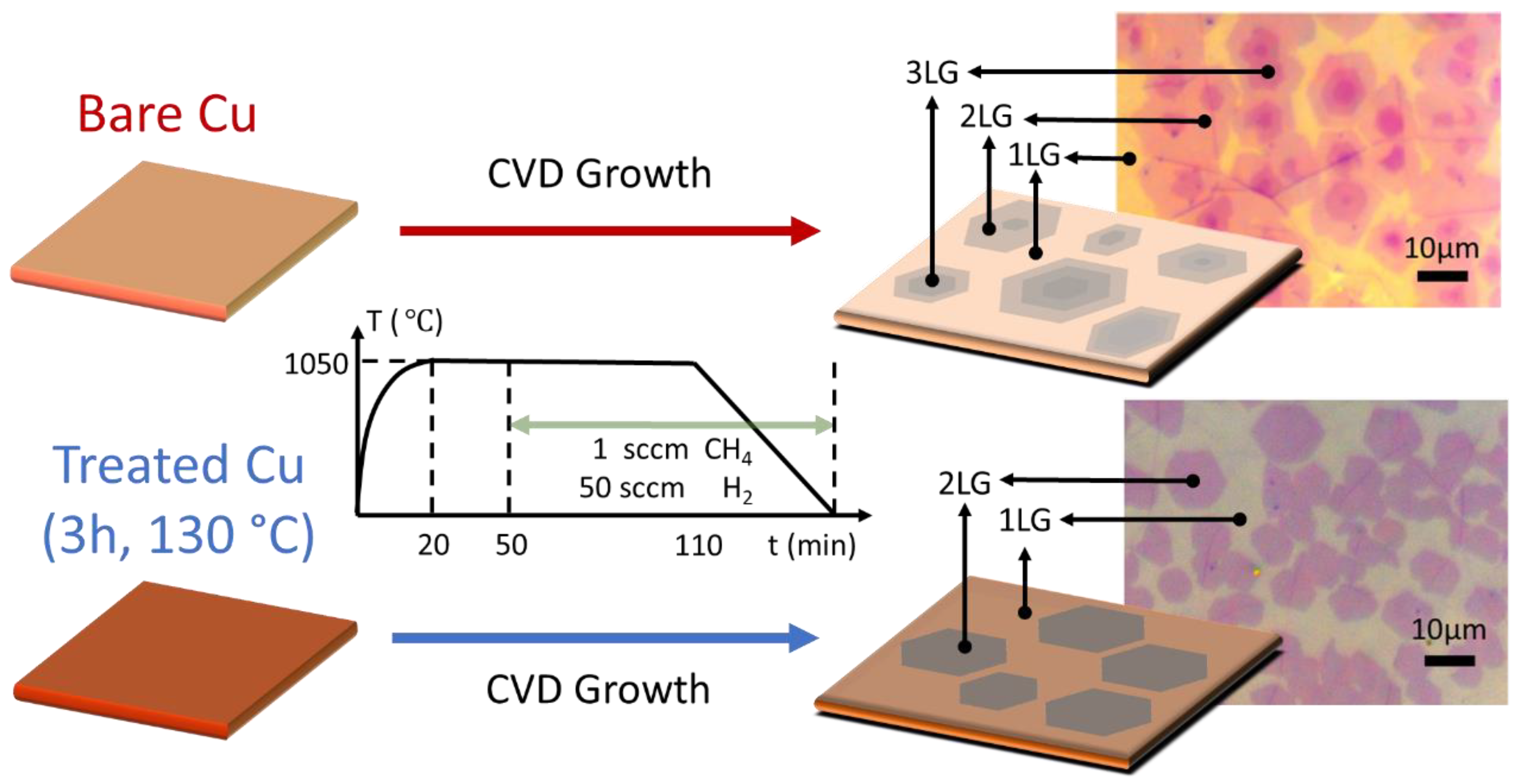
Figure 1. Schematics showing the low-pressure chemical vapor deposition (LPCVD) process for graphene growth on bare and treated Cu substrates. Insets: Optical images of the produced graphene samples transferred on separate SiO2/Si substrates, grown using the two different types of Cu substrates as indicated. 1LG, 2LG, and 3LG represent monolayer, bilayer, and tri-layer graphene, respectively.
Crystals 10 00308 g001
Figure 2. Optical microscopy analysis of graphene samples: (A) Typical optical images of graphene samples grown on bare (left panel) and treated (right panel) Cu, then transferred onto SiO2/Si substrates; (B) Pixel counts as a function of gray values for two microscopy images of typical graphene samples grown on bare (left panel) and treated Cu (right panel) substrates; (C) Statistical labeling for each layer of graphene; (D) Occurrence probability for different graphene layers, statistically identified using the method shown in (B,C), from 20 typical optical images taken from both types of graphene samples (10 each). Multilayer graphene (MLG) represents 3LG, 4LG, and above.
Crystals 10 00308 g002
Figure 3. Raman analysis of graphene samples: (A,D) Optical images of graphene samples grown on treated and bare Cu, respectively; (B,E) the corresponding Raman spectra taken at different positions as indicated; (C,F) the corresponding Raman maps of I2D/IG ratios. Laser spot size was about 500 nm, and the mapping step size was 200 nm. All scale bars are 5 μm.
Crystals 10 00308 g003
Figure 4. AI-algorithm-enabled Raman analysis of a typical graphene sample grown on treated Cu, where layer-by-layer graphene growth occurs. (A) The three parameters extracted from each Raman spectrum (i.e., ω G , ω 2 D , and Γ 2 D ) were selected as clustering features. (B) The corresponding Raman data after k-means algorithm classification. A total of 18,000 Raman spectra were clustered into two classes only. By reading the mean value ( ω G ¯ , ω 2 D ¯ , Γ 2 D ¯ ) of each class, we identified Class I and II as the Raman data attributed to 1LG and quasi-AB-stacked 2LG, respectively.
Crystals 10 00308 g004
Figure 5. AI-algorithm-enabled Raman analysis of a typical graphene sample grown on bare Cu where layer-plus-island graphene growth occurs. (A) The three parameters extracted from each Raman spectrum (i.e., ω G , ω 2 D , and Γ 2 D ) were selected as clustering features. (B) The corresponding Raman data after k-means algorithm classification. By reading the mean value ( ω G ¯ , ω 2 D ¯ , Γ 2 D ¯ ) of each cluster, we identified Class I to V as the Raman data attributed to 1LG, quasi-AB-stacked 2LG, larger-twisting-angle 2LG, 3LG, and MLG, respectively.
Crystals 10 00308 g005