Article

The Effect of Lath Martensite Microstructures on the Strength of Medium-Carbon Low-Alloy Steel

1
Shenyang National Laboratory for Materials Science, Institute of Metal Research, Chinese Academy of Sciences, Shenyang 110016, China
2
School of Materials Science and Engineering, University of Science and Technology of China, Hefei 230026, China
*
Authors to whom correspondence should be addressed.
Crystals 2020, 10(3), 232; https://doi.org/10.3390/cryst10030232
Submission received: 7 March 2020 / Revised: 17 March 2020 / Accepted: 19 March 2020 / Published: 23 March 2020
(This article belongs to the Special Issue Microstructural and Mechanical Characterization of Alloys)

Abstract

:
Different austenitizing temperatures were used to obtain medium-carbon low-alloy (MCLA) martensitic steels with different lath martensite microstructures. The hierarchical microstructures of lath martensite were investigated by optical microscopy (OM), electron backscattering diffraction (EBSD), and transmission electron microscopy (TEM). The results show that with increasing the austenitizing temperature, the prior austenite grain size and block size increased, while the lath width decreased. Further, the yield strength and tensile strength increased due to the enhancement of the grain boundary strengthening. The fitting results reveal that only the relationship between lath width and strength followed the Hall–Petch formula of. Hence, we propose that lath width acts as the effective grain size (EGS) of strength in MCLA steel. In addition, the carbon content had a significant effect on the EGS of martensitic strength. In steels with lower carbon content, block size acted as the EGS, while, in steels with higher carbon content, the EGS changed to lath width. The effect of the Cottrell atmosphere around boundaries may be responsible for this change.

1. Introduction

Medium-carbon low-alloy (MCLA) steel has an excellent combination of strength, toughness and hardenability and is widely used in structural components with large sections, such as generator spindles and automotive crankshafts [1,2,3]. Lath martensite is a typical microstructure seen in MCLA steel after quenching. There are several elements in lath martensitic microstructures. Prior austenite grains (PAGs) are divided into several packets, which consist of parallel blocks. The blocks are composed of laths, arranged parallel to each other. Low-angle grain boundaries (LAGBs) exist among laths, while high-angle grain boundaries (HAGBs) exist among packets and blocks [4,5,6].
An early work [7] indicated that the PAG size was the effective grain size (EGS) of strength in the Hall–Petch formula. Subsequently, the Hall–Petch relationship between yield strength and packet size was discovered by Swarr et al. in Fe–0.2C alloy [8], by Roberts in Fe–Mn alloy [9], and by Wang et al. in 17CrNiMo6 steel [10]. With the development of characterization technology, Morito et al. [11] revealed that the block width in Fe–0.2C and the Fe–0.2C–2Mn alloys is the key structural parameter controlling the strength of lath martensite by utilizing electron backscattered diffraction (EBSD). Similar results were presented by Zhang et al. [12], Long et al. [13], and Li et al. [14]. However, the martensite lath was also considered to be an effective control unit of strength in the research of Smith et al. in 42CrMo steel [15] and Kim et al. in Fe-0.55C alloy [16]. So far, there are still controversies regarding the EGS of strength in lath martensite.
Previous studies focused mainly on low-carbon steels. However, reports are scarce on the relationship between lath martensite microstructures and strength in medium-carbon steels has been. In lath martensite, carbon atoms segregate around dislocations and grain boundaries, rather than interstitial solution in the lattice [17]. The different carbon contents in steel can change the amount of segregated carbon atoms around the grain boundaries, which therefore affects its strength. In fact, research on low-carbon steel [8,9,10,11,12,13,14] draws the conclusion that the block/packet size is the key structural parameter in controlling the strength of lath martensite, while research on medium-carbon steel [16,18] tends to suggest that the strength depends primarily on the lath width. However, little work has been done on medium-carbon steel. Therefore, it is necessary to study the relationship between the martensite multi-level microstructure and strength in medium-carbon steel in order to verify the above finding.
In this work, austenitizing temperatures of 850–940 °C were used to obtain different sizes of PAG, block, and lath in the experimental MCLA steel. Then, optical microscopy (OM), EBSD, and transmission electron microscopy (TEM) were utilized to quantify the multi-level structural parameters at different austenitizing temperatures. The classical Hall–Petch formula of strength was assessed with PAG size, block width, and lath width respectively in order to clarify the EGS that governs the strength in the experimental MCLA steel. In addition, the influence of carbon content on the effective grain size of strength is summarized and further elucidated based on the above results as well as data from published research.

2. Experimental Procedures

2.1. Materials and Heat Treatment

The MCLA martensite steel used in this investigation was melted in a vacuum furnace and cast into a 25 kg ingot. Then, the ingot was forged into a round rod. Specimens with a dimension of 60 mm × 60 mm × 60 mm were taken from the rods. The chemical composition of the experimental steel was determined by an inductively coupled plasma emission spectrometer (ICP-6300, Thermo Fisher Scientific Company, Waltham, USA), and the result is shown in Table 1. Figure 1 shows the dilatometric curve of test steel, indicating that the Ac1 (austenitization starting point) and Ac3 (austenitization ending point) were respectively 735 °C and 818 °C. Based on the dilatometric curve, the heat treatment processes were as follows. First, the specimens were annealed at 860 °C for 3 h, followed by furnace cooling. Then the specimens were austenitized at different temperatures of 850, 880, 910, and 940 °C for 3 h, and quenched by water cooling.

2.2. Microstructure Observation

The PAGs were observed via OM (AxioCam MRc5, ZEISS Company, Oberkochen, Germany). The OM specimens were etched with a supersaturated picric acid solution, which was configured with 25 g of water and 0.7 g of picric acid. The martensite packets and blocks were characterized with EBSD. As the lath width is generally 0.2–0.3 μm [5,12,13], the step size was chosen to be 0.2 μm. The block widths were measured with reference to EBSD maps, as processed with the Oxford Instruments Channel 5 HKL software. The martensite laths were observed via TEM (Tecnai G220, FEI Company, Hillsboro, AL, USA). At least 500 PAGs, 300 blocks, and 200 laths were measured in order to ascertain the average PAG size, block width, and lath width. The preparation methods used for the TEM samples and EBSD samples can be found in our previous research [3]. The dislocation densities of experimental steels were determined via X-ray diffraction (XRD) (D/Max-2500PC, Rigaku Company, Tokyo, Japan) with Cu Kα radiation (λ = 1.5406 Å). The scanning angle was 20–100°, and the scanning speed was 1°/min.

2.3. Mechanical Tests

The tensile tests were performed with a Z150 tensile machine (Zwick/Roell Company, Ulm, Germany). At least three standard tensile samples with a diameter of 5 mm were used for each heat treatment condition.

3. Results and Discussion

3.1. Microstructural Characterization

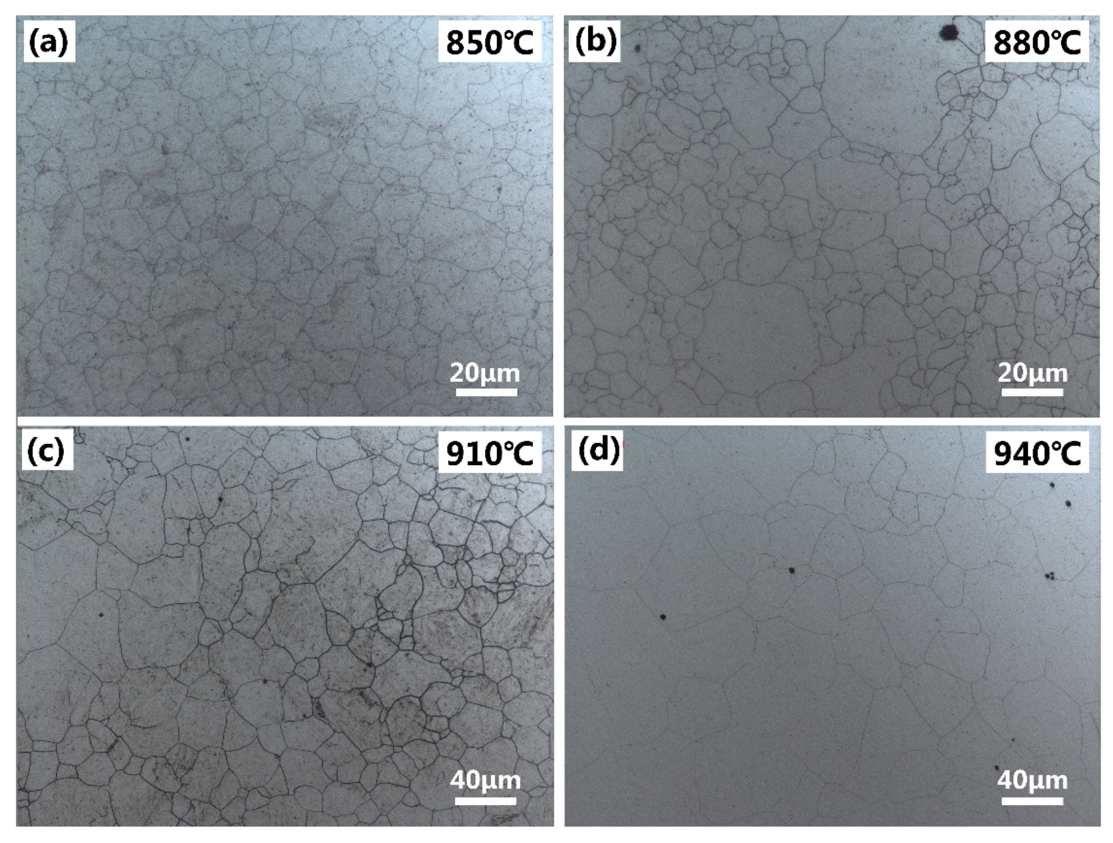
Figure 2 shows the typical morphologies of PAG in MCLA martensitic steel when austenitized at different temperatures. The average PAG sizes of samples austenitized at different temperatures are shown in Figure 3a. The PAGs were uniform after austenitizing at 850 °C, as shown in Figure 2a. As the austenitizing temperature rises to 880 °C some PAGs coarsened severely, leading to an increase in the average PAG size. When the austenitizing temperature was increased further, the dissolution of fine precipitates weakened the pinning effect on the grain boundary [13], resulting in the fast growth rate of PAG size, as shown in Figure 3a.
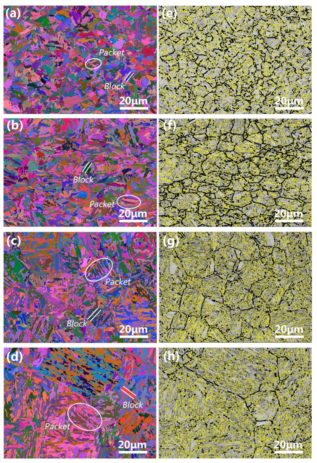
The EBSD orientation maps of MCLA steel austenitized at different temperatures are shown in Figure 4, and the measured block width ( d B ) is shown in Figure 3b. It can be seen that the PAGs are composed of several martensite packets which consist of blocks with similar extension directions. The PAG boundaries are HAGBs with a misorientation less than 45° (black lines) [13]. The HAGBs with a misorientation higher than 45° (yellow lines) are the martensite packet and block boundaries, which are distributed inside the PAGs. As the austenitizing temperature increased, the martensite blocks were arranged in a more orderly fashion. This is due to the weakening of the resistance of the lath nucleation and growth at high austenitizing temperatures [13]. At the same time, the sizes of the packets and blocks increased significantly. As shown in Figure 3b, as the austenitizing temperature increased from 850 °C to 940 °C, the average d B increased from ~1.8 μm to ~2.5 μm.
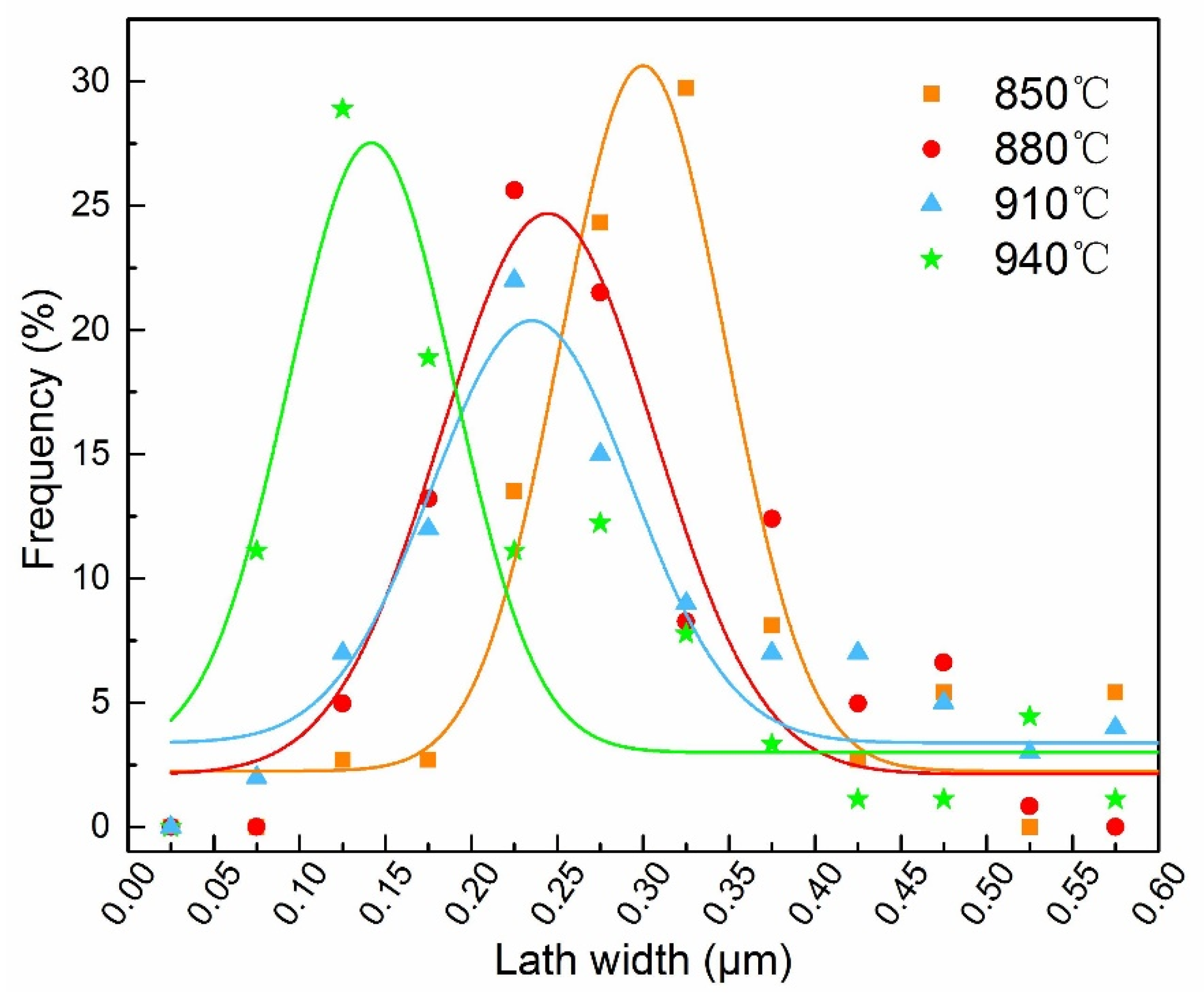
The TEM observations of martensite laths in as-quenched MCLA steels are shown in Figure 5, and the measured lath width ( d L ) is shown in Figure 3c. The laths arrange in a parallel manner in packets, and contain high-density dislocations. The d L gradually decreased with increasing austenitizing temperature. The size distribution of d L is shown in Figure 6. It can be seen that all distribution curves tend to show a normal distribution. The peak of the normal distribution curve moved to the left as the austenitizing temperature increased, revealing that higher austenitizing temperature resulted in a fine lath width. The high austenitizing temperature promotes the dissolution of residual carbides into austenite, which decreases the martensite starting temperature and increases the nucleation rate of martensite [19,20]. The low martensite starting temperature, coupled with the high nucleation rate, result in small d L [13,21].
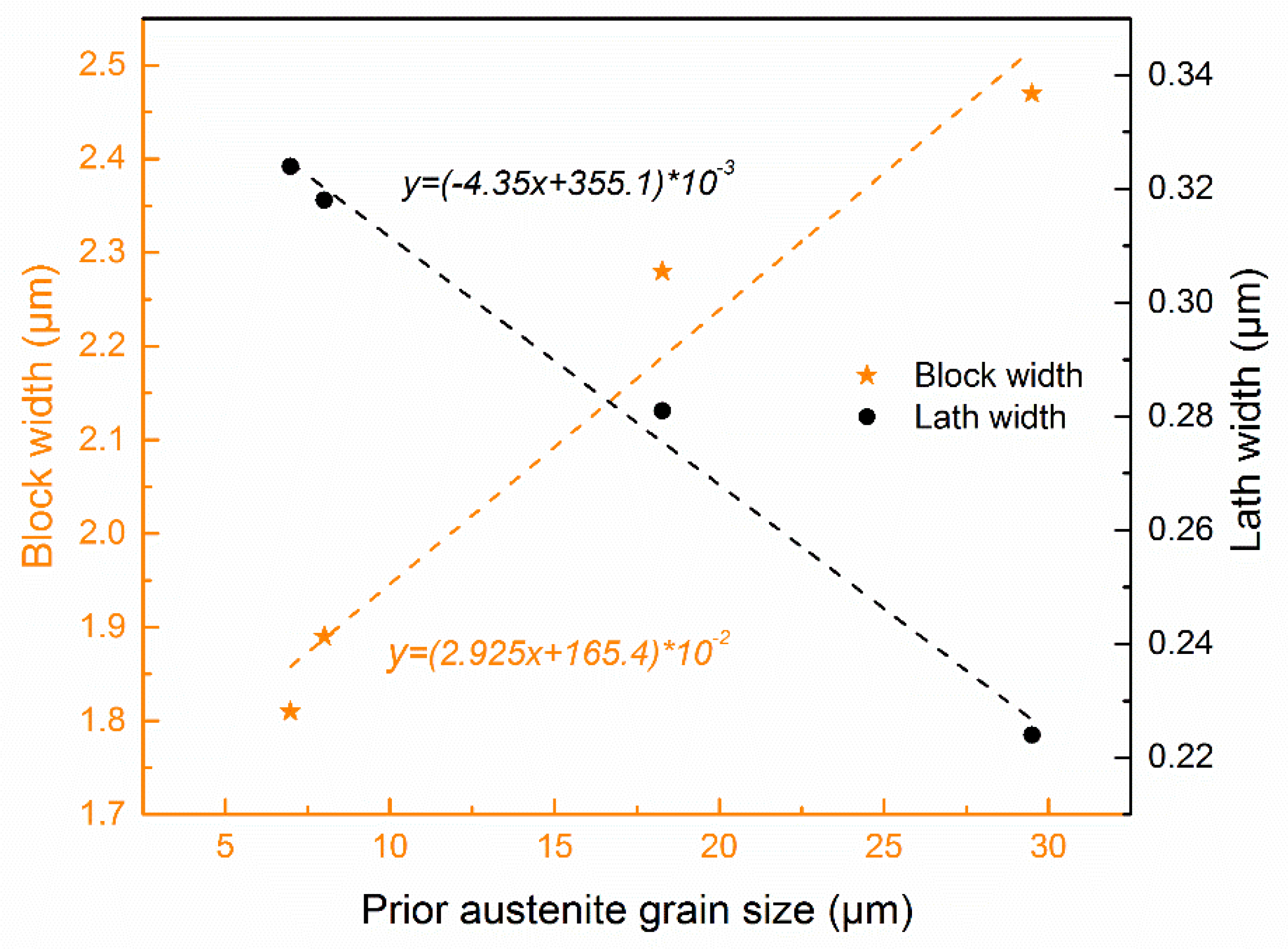
Figure 7 shows the relationship between d B , d L , and PAG size, respectively. The d B increased linearly and the d L decreased linearly with the PAG size at different austenitizing temperatures. For example, the d B changed from 2.28 μm to 2.47 μm as the PAG size increased from 18.3 μm to 29.5 μm, while the d L decreased from 281 nm to 224 nm. Similar results were reported by Long et al. [13].

3.2. Tensile Properties

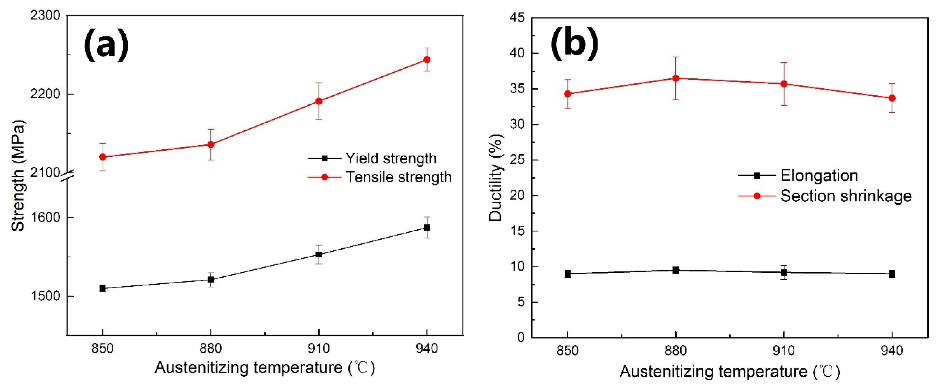
Figure 8 shows the relationship between the tensile properties and the austenitizing temperature. When the quenching temperature was increased from 850 °C to 940 °C, the yield strength increased from 1510 MPa to 1591 MPa while the tensile strength increased from 2120 MPa to 2244 MPa. The elongation and section shrinkage were similar for all specimens, with the former being ~8% and the latter being ~35%. The high density of dislocations and boundaries restricted the movement of dislocations, resulting in the poor ductility of all of the samples.

3.3. Effect of Lath Martensite Microstructures on the Strength

Four strengthening contributions were considered in this work: solid-solution strengthening ( Δ σ s ), precipitation strengthening ( Δ σ p ), dislocation strengthening ( Δ σ d ), and grain boundary strengthening ( Δ σ g ). The yield strength can be expressed as Equation (1) [22,23]:
σ Y S = Δ σ 0 + Δ σ s + Δ σ p + Δ σ d + Δ σ g
where   σ Y S is the yield strength (MPa) and Δ σ 0 is the intrinsic strength of the matrix (MPa), which was estimated to be 85~88 MPa [24,25].
The precipitation strengthening can be expressed as Equation (2) in light of the Orowan relationship [26,27]:
Δ σ p = 0.538 G b f 0.5 D l n ( D 2 b )
where f is the volume fraction of the carbide, D is the mean particle size, and b is the Burgers vector of 0.248 nm. In this study, the carbides dissolved almost completely into the austenite and almost no precipitates remained in the microstructure. Therefore, the value of Δ σ p can be regarded as 0 MPa while Δ σ s was similar in all specimens.
Δ σ d can be expressed as Equation (3) [27]:
Δ σ d = α M G b ρ 0.5
where M is the Taylor factor, α is a constant of 0.435, G is the shear modulus, and ρ is the dislocation density.
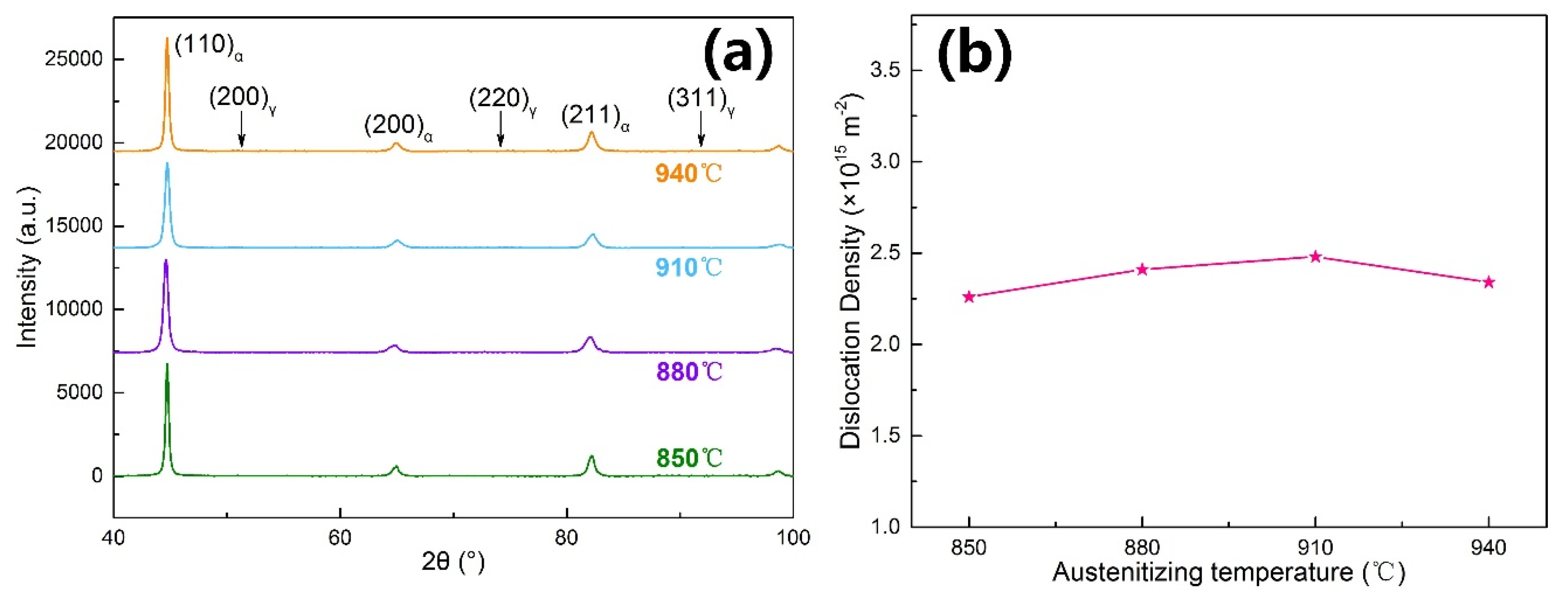
Figure 9 shows the XRD patterns of specimens austenitized at different temperatures. No diffraction peak of retained austenite could be observed in the XRD pattern, meaning that the of retained austenite content was very small. The dislocation densities were calculated according to the XRD results. The calculation method is drawn from references [28,29]. The measured dislocation densities are shown in Figure 9b. It is shown that the dislocation density only changed slightly with the increase of austenitizing temperature, which is consistent with reference [30]. According to Equation (3), the Δ σ d values were considered to be identical. Therefore, the change of grain boundary strengthening led to an increase of yield strength when the austenitizing temperature was increased. Under such circumstances, the yield strength is used as the value of grain boundary strengthening.
The grain boundary strengthening can be described by the classic Hall–Petch relationship:
σ Y s = σ 0 + k y d 0.5
where k y is the Hall–Petch slope and d is the EGS. Evidently, the smaller the EGS, the more the boundaries can hinder dislocation motion, and the higher the strength. The relationship between the strength and lath martensite microstructure sizes is shown in Figure 10. The strength decreased linearly with d R 0.5 and d B 0.5 , while it increased linearly with d L 0.5 . That is, only the relationship between strength and lath width followed the Hall–Petch formula. In other words, the lath width was finally determined as the EGS of strength in the experimental MCLA steel.
In lath martensite, the PAG boundaries, packet boundaries, and block boundaries are HAGBs, while the lath boundaries are LAGBs. Lath width acting as the EGS means that the LAGBs play a dominant role in hindering dislocation motion. Many previous studies have suggested that only HAGBs can hinder the dislocation motion effectively and cause strengthening [31,32,33]. However, recent research has come to the opposite conclusion. Du et al. [34] demonstrated that both high- and low-angle grain boundaries act as effective barriers to dislocation movement via uniaxial micro-tensile tests. Chen et al. [35] directly observed that a large number of dislocations accumulate in front of the lath boundaries via in situ TEM experiments, proving that the LAGB is capable of hindering dislocation motion and causing strengthening. These findings act as further proof of our results showing that lath width can act as the EGS in MCLA steel.

3.4. Effect of Carbon Content on the Effective Grain Size of Strength

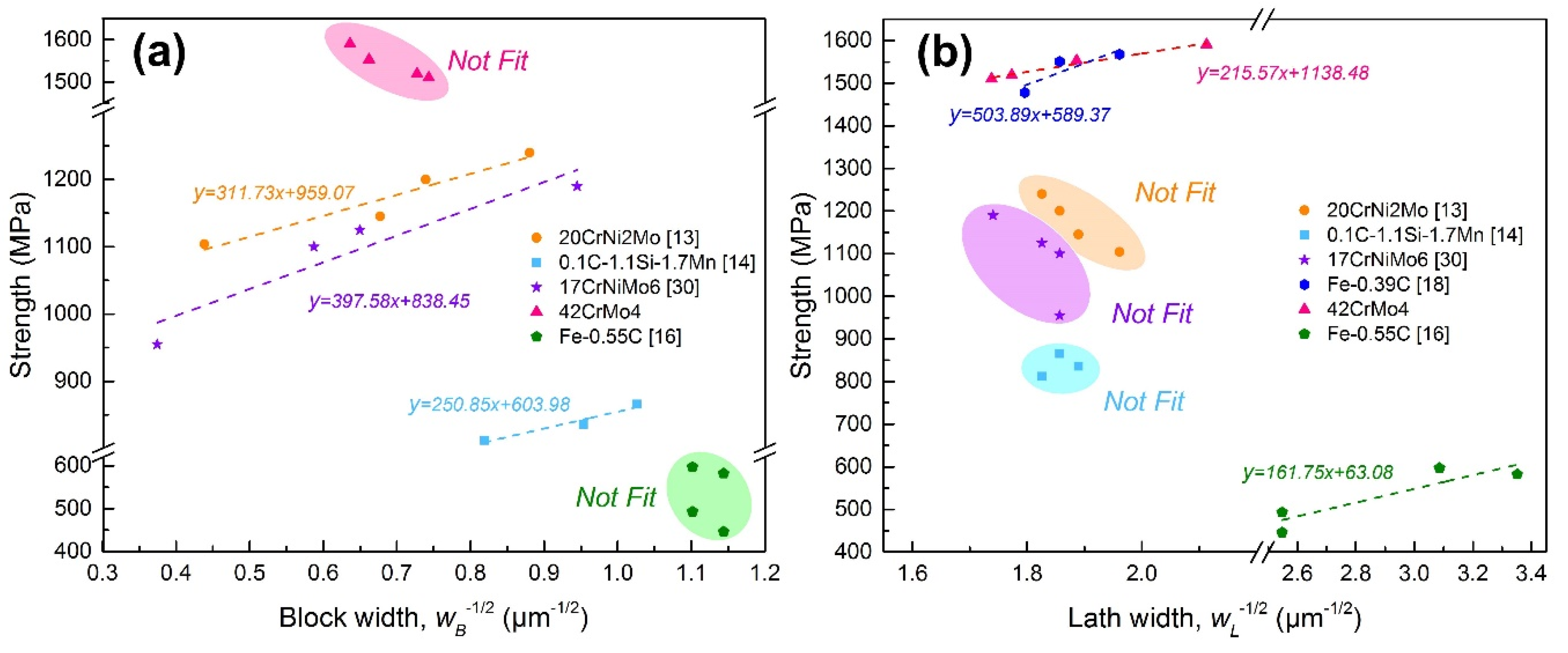
Figure 11 summarizes the relationship between strength and lath martensite microstructure sizes in recent studies [13,14,16,18,30]. As shown in Figure 11a, with increasing of d B 0.5 , the strength increased in steels with carbon content below 0.2 wt%, while it decreased linearly in steels with a carbon content above 0.4 wt%. Figure 11b shows the relationship between strength and lath width, revealing the opposite result to that shown in Figure 11a. The relationship between the lath width and strength only followed the Hall–Petch relationship in the medium-carbon steels. Thus, it can be concluded that the EGS of strength seems to be related to the carbon content. In steels with lower carbon content the block size acted as the EGS. While, in steels with higher carbon content, the EGS changed to lath width. That is, the carbon content of steel affects the role of HAGB and LAGB in preventing dislocation movement. When the carbon content is low, HAGBs are the most significant barriers to the dislocation motion, and consequently the hindering effect of LAGB can be ignored. With an increase in carbon content, the hindering effect of LAGB on dislocation movement becomes more important, leading to the gradual transformation of EGS to lath width.
The effect of the Cottrell atmosphere around boundaries may be responsible for this change. Carbon atoms segregate around boundaries and dislocations to reduce distortion energy, leading to the formation of the Cottrell atmosphere [36,37,38]. During the slipping process, the dislocations are forced to move along with the Cottrell atmospheres, resulting in the so-called “drag effect”, which can effectively increase the resistance of the dislocation movement and pin the dislocation. Previous studies have revealed that the drag effect enhances when the carbon content is increased [36,39]. When the carbon content is low (lower than 0.2 wt%), the drag effect of the Cottrell atmosphere becomes weak and the hindering effect of grain boundaries on dislocation motion is mainly dependent on its distorted lattice structure. In this case, the barrier effect of HAGB on dislocation movement is much stronger than that of LAGB. Accordingly, the block width acts as EGS in steels with low carbon content. With the increase of carbon content in steel, the drag effect of the Cottrell atmosphere is greatly enhanced. Accordingly, the difference between the hindering effect of HAGB and LAGB on the dislocation motion, which is caused by the lattice structure, is reduced. When the carbon content is high enough (higher than 0.4 wt%), the LAGB, which holds the absolute advantage in quantity, becomes the dominant factor in hindering dislocation movement. Therefore, the lath width becomes the EGS of strength in steels with high carbon content.

4. Conclusions

We studied the effect of martensite microstructures on the strength of MCLA steel. The results are summarized as follows:
  • When increasing the austenitizing temperature, the PAG size and block size become larger, while the lath width decreases in the experimental MCLA steel. Both the increment of block width and the reduction of the lath width show a linear variation with the increase of the PAG size.
  • When the austenitizing temperature rises, the yield strength and the tensile strength are elevated due to the enhancement of the grain boundary strengthening. The Hall–Petch fitting results reveal that only the relationship between lath width and strength follows the Hall–Petch formula, which indicates that the lath width is the effective grain size of strength in the experimental MCLA steel.
  • Carbon content has a significant effect on the EGS of strength in lath martensite. In terms of low-carbon steels with a carbon content lower than 0.2 wt%, block size acts as the effective grain size, while the EGS tends to be lath width in steels with a high carbon content of over 0.4 wt%. The effect of the Cottrell atmosphere around boundaries is considered to be responsible for this change.

Author Contributions

Conceptualization, C.S., Y.C., and P.F.; methodology, C.S.; validation, C.S., Y.C., and P.F.; formal analysis, C.S.; investigation, C.S., Y.C., and P.F.; resources, P.F. and H.L. (Hongwei Liu); data curation, C.S. and P.F.; writing—original draft preparation, C.S.; writing—review and editing, C.S., Y.C., H.L. (Hanghang Liu), H.L. (Hongwei Liu), and N.D.; visualization, C.S., N.D. and H.L. (Hanghang Liu); project administration, P.F. and H.L. (Hongwei Liu); funding acquisition, H.L. (Hongwei Liu), P.F., and H.L. (Hanghang Liu) All authors have read and agreed to the published version of the manuscript.

Funding

This research was funded by the National Natural Science Foundation of China (Grant No. 51701225), the Project to Strengthen Industrial Development at the Grass-roots Level (Grant No.TC190A4DA/35), the Independent & Controllable Manufacturing of Advanced Bearing, the Innovation project of the cutting-edge basic research and key technology by SYNL (Grant No.L2019R36), the Young Talent Project by SYNL (Grant No.L2019F33) and the China Postdoctoral Science Foundation (Grant No. 2019M661153).

Conflicts of Interest

The authors declare no conflicts of interest.

References

  1. Morris, J.W., Jr.; Kinney, C.; Pytlewski, K.; Adachi, Y. Microstructure and cleavage in lath martensitic steels. Sci. Technol. Adv. Mater. 2013, 144, 014208. [Google Scholar]
  2. Kinney, C.C.; Pytlewski, K.R.; Khachaturyan, A.G.; Morris, J.W., Jr. The microstructure of lath martensite in quenched 9Ni steel. Acta Mater. 2014, 69, 372–385. [Google Scholar] [CrossRef]
  3. Sun, C.; Fu, P.X.; Liu, H.W.; Liu, H.H.; Du, N.Y. Effect of tempering temperature on the low temperature impact toughness of 42CrMo4-V steel. Metals Open Access Metall. J. 2018, 8, 232. [Google Scholar] [CrossRef] [Green Version]
  4. Shibataa, A.; Nagoshi, T.; Sone, M.; Morito, S.; Higo, Y. Evaluation of the block boundary and sub-block boundary strengths of ferrous lath martensite using a micro-bending test. Mater. Sci. Eng. A 2010, 527, 7538–7544. [Google Scholar] [CrossRef]
  5. Morito, S.; Tanaka, H.; Konishi, R.; Furuhara, T.; Maki, T. The morphology and crystallography of lath martensite in Fe-C alloys. Acta Mater. 2003, 51, 1789–1799. [Google Scholar] [CrossRef]
  6. Morito, S.; Huang, X.; Furuhara, T.; Maki, T.; Hansen, N. The morphology and crystallography of lath martensite in alloy steels. Acta Mater. 2006, 54, 5323–5331. [Google Scholar] [CrossRef]
  7. Grange, R.A. Strengthening steel by austenite grain refinement. Trans. ASM 1966, 59, 26–48. [Google Scholar]
  8. Swarr, T.; Krauss, G. The effect of structure on the deformation of as-quenched and tempered martensite in a Fe-0.2 pct C alloy. Metall. Trans. A 1976, 7A, 41–48. [Google Scholar] [CrossRef]
  9. Roberts, M.J. Effect of transformation substructure on the strength and toughness of Fe-Mn alloys. Metall. Trans. 1970, 1, 3287–3294. [Google Scholar]
  10. Wang, C.F.; Wang, M.Q.; Shi, J.; Hui, W.J.; Dong, H. Effect of microstructure refinement on the strength and toughness of low alloy martensitic steel. J. Mater. Sci. Technol. 2007, 23, 659–664. [Google Scholar]
  11. Morito, S.; Yoshida, H.; Maki, T.; Huang, X. Effect of block size on the strength of lath martensite in low carbon steels. Mater. Sci. Eng. A 2006, 438–440, 237–240. [Google Scholar] [CrossRef]
  12. Zhang, C.Y.; Wang, Q.F.; Ren, J.X.; Li, R.X.; Wang, M.Z.; Zhang, F.C.; Yan, Z.S. Effect of microstructure on the strength of 25CrMo48V martensitic steel tempered at different temperature and time. Mater. Des. 2012, 36, 220–226. [Google Scholar] [CrossRef]
  13. Long, S.L.; Liang, Y.L.; Jiang, Y.; Liang, Y.; Yang, M.; Yi, Y.L. Effect of quenching temperature on martensite multi-level microstructures and properties of strength and toughness in 20CrNi2Mo steel. Mater. Sci. Eng. A 2016, 676, 38–47. [Google Scholar] [CrossRef]
  14. Li, S.C.; Zhu, G.M.; Kang, Y.L. Effect of substructure on mechanical properties and fracture behavior of lath martensite in 0.1C-1.1Si-1.7Mn steel. J. Alloy. Compd. 2016, 675, 104–115. [Google Scholar] [CrossRef]
  15. Smith, D.W.; Hehemann, R.F. Influence of structural parameters on the yield strength of tempered martensite and lower bainite. JISI 1971, 476–481. [Google Scholar]
  16. Kim, B.; Boucard, E.; Sourmail, T.; Martín, D.S.; Gey, N.; Rivera-Díaz-del-Castillo, P.E.J. The influence of silicon in tempered martensite: Understanding the microstructure–properties relationship in 0.5–0.6 wt.% C steels. Acta Mater. 2014, 68, 169–178. [Google Scholar] [CrossRef]
  17. Galindo-Nava, E.I.; Rivera-Díaz-del-Castillo, P.E.J. A model for the microstructure behaviour and strength evolution in lath martensite. Acta Mater. 2015, 98, 81–93. [Google Scholar] [CrossRef] [Green Version]
  18. Wang, J.; Xu, Z.; Lu, X. Effect of the Quenching and Tempering Temperatures on the Microstructure and Mechanical Properties of H13 Steel. J. Mater. Eng. Perform 2020. [Google Scholar] [CrossRef]
  19. Speich, G.R.; Warlimont, H. Yield strength and transformation substructure of low-carbon martensite. J. Iron Steel Res. 1968, 206, 385–394. [Google Scholar]
  20. Su, T.Y.H. Effect of lath martensite morphology on the mechanical properties steel. Heat. Treat. 2009, 3, 1–24. [Google Scholar]
  21. Wang, S.X. Metal Heat Treatment Principles and Process; Harbin Industrial of Technology Press: Harbin, China, 2009. [Google Scholar]
  22. Chen, J.; Lv, M.Y.; Tang, S.; Liu, Z.Y.; Wang, G.D. Influence of cooling paths on microstructural characteristics and precipitation behaviors in a low carbon V–Ti microalloyed steel. Mater. Sci. Eng. A 2014, 594, 389–393. [Google Scholar] [CrossRef]
  23. Yen, H.W.; Chen, P.Y.; Huang, C.Y.; Yang, J.R. Interphase precipitation of nanometer-sized carbides in a titanium–molybdenum-bearing low-carbon steel. Acta Mater. 2011, 59, 6264–6274. [Google Scholar] [CrossRef]
  24. Halfa, H. Recent trends in producing ultrafine grained steels. J. Miner. Mater. Charact. Eng. 2014, 2, 428–469. [Google Scholar] [CrossRef]
  25. Cheng, X.Y.; Zhang, H.X.; Li, H.; Shen, H.P. Effect of tempering temperature on the microstructure and mechanical properties in mooring chain steel. Mater. Sci. Eng. A 2015, 636, 164–171. [Google Scholar] [CrossRef]
  26. Peng, H.L.; Hu, L.; Ngai, T.W.; Li, L.J.; Zhang, X.L.; Xie, H.; Gong, W.P. Effects of austenitizing temperature on microstructure and mechanical property of a 4-GPa-grade PM high-speed steel. Mater. Sci. Eng. A 2018, 719, 21–26. [Google Scholar] [CrossRef]
  27. Yong, Q.L. Second Phases in Structural Steels; Metallurgical Industry Press: Beijing, China, 2006. [Google Scholar]
  28. HajyAkbary, F.; Sietsma, J.; B€ottger, A.J.; Santofimia, M.J. An improved X-ray diffraction analysis method to characterize dislocation density in lath martensitic structures. Mater. Sci. Eng. A 2015, 639, 208–218. [Google Scholar] [CrossRef]
  29. Williamson, G.K.; Smallman, R.E. Dislocation densities in some annealed and cold-worked metals from measurements on the x-ray Debye-Scherrer spectrum. Philos. Mag. 1955, 1, 34–46. [Google Scholar] [CrossRef]
  30. Wang, C.F. Study of Microstructure Control Unit on Strength and Toughness in Low Alloy Martensite Steel. Ph. D Thesis, Central Iron & Steel Research Institute, Beijing, China, 2008. [Google Scholar]
  31. Shibata, A.; Nagoshi, T.; Sone, M.; Morito, S.; Higo, Y. Micromechanical characterization of deformation behavior in ferrous lath martensite. J. Alloys. Compd. 2013, 577, S555–S558. [Google Scholar] [CrossRef]
  32. Lim, S.; Shin, C.; Heo, J.; Kim, S.; Jin, H.; Kwon, J.; Guim, H.; Jang, D. Micropillar compression study of the influence of size and internal boundary on the strength of HT9 tempered martensitic steel. J. Nucl. Mater. 2018, 503, 263–270. [Google Scholar] [CrossRef]
  33. Mine, Y.; Hirashita, K.; Takashima, H.; Matsuda, M.; Takashima, K. Micro-tension behaviour of lath martensite structures of carbon steel. Mater. Sci. Eng. A 2013, 560, 535–544. [Google Scholar] [CrossRef]
  34. Du, C.; Hoefnagels, J.P.M.; Vaes, R.; Geers, M.G.D. Block and sub-block boundary strengthening in lath martensite. Scr. Mater. 2016, 116, 117–121. [Google Scholar] [CrossRef] [Green Version]
  35. Chen, S.J.; Yu, Q. The role of low angle grain boundary in deformation of titanium and its size effect. Scr. Mater. 2019, 163, 148–151. [Google Scholar] [CrossRef]
  36. Hutchinson, B.; Hagström, J.; Karlsson, O.; Lindell, D.; Tornberg, M.; Lindberg, F.; Thuvander, M. Microstructures and hardness of as-quenched martensites (0.1–0.5% C). Acta Mater. 2011, 59, 5845–5858. [Google Scholar] [CrossRef]
  37. Takahashi, J.; Ishikawa, K.; Kawakami, K.; Fujioka, M.; Kubota, N. Atomic-scale study on segregation behavior at austenite grain boundaries in boron- and molybdenum-added steels. Acta Mater. 2017, 133, 41–54. [Google Scholar] [CrossRef]
  38. Miyamoto, G.; Goto, A.; Takayama, N.; Furuhara, T. Three-dimensional atom probe analysis of boron segregation at austenite grain boundary in a low carbon steel - Effects of boundary misorientation and quenching temperature. Scr. Mater. 2018, 154, 168–171. [Google Scholar] [CrossRef]
  39. Waseda, O.; Veiga, R.G.; Morthomas, J.; Chantrenne, P.; Becquart, C.S.; Ribeiro, F.; Jelea, A.; Goldenstein, H.; Perez, M. Formation of carbon Cottrell atmospheres and their effect on the stress field around an edge dislocation. Scr. Mater. 2017, 129, 16–19. [Google Scholar] [CrossRef]
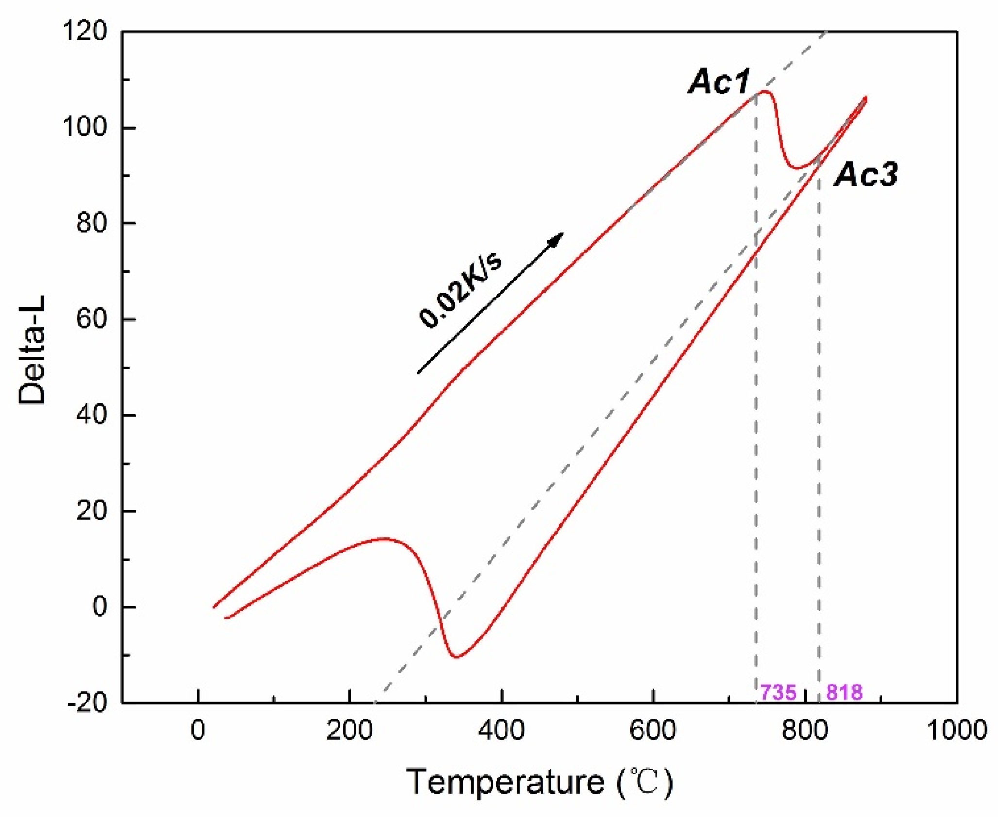
Figure 1. The dilatometric curve of the experimental MCLA steel.
Crystals 10 00232 g001
Figure 2. Prior austenite grain of MCLA martensitic steel austenitized at the different temperatures of (a) 850 °C, (b) 880 °C, (c) 910 °C, and (d) 940 °C observed by optical microscopy.
Crystals 10 00232 g002
Figure 3. Relationship between austenitizing temperature and (a) prior austenite grain size, (b) block width, and (c) lath width.
Crystals 10 00232 g003
Figure 4. Electron backscattered diffraction (EBSD) of all Euler maps and the corresponding band contrast maps of MCLA martensitic steel austenitized at different temperatures of (a,e) 850 °C; (b,f) 880 °C; (c,g) 910 °C; (d,h) 940 °C (black lines: 45° > θ > 15°; and yellow lines: θ > 45°).
Crystals 10 00232 g004
Figure 5. Transmission electron microscopy (TEM) micrographs of MCLA steel austenitized at the different temperatures: (a) 850 °C, (b) 880 °C, (c) 910 °C, and (d) 940 °C.
Crystals 10 00232 g005
Figure 6. Size distribution of lath width at different austenitizing temperatures.
Crystals 10 00232 g006
Figure 7. Dependence of block width and lath width on prior austenite grain size in MCLA steel.
Crystals 10 00232 g007
Figure 8. Tensile properties of MCLA martensite steel at different austenitizing temperatures: (a) yield strength and tensile strength; (b) elongation and section shrinkage.
Crystals 10 00232 g008
Figure 9. (a) X-ray diffraction (XRD) spectra and (b) dislocation density of MCLA martensitic steel austenitized at 850–940 °C.
Crystals 10 00232 g009
Figure 10. Strength as a function of (a) prior austenite grain (PAG) size ( d R ), (b) block width ( d B ), and (c) lath width ( d L ).
Crystals 10 00232 g010
Figure 11. Yield strength as a function of (a) block width and (b) lath width.
Crystals 10 00232 g011
Table 1. Chemical compositions of the experimental medium-carbon low-alloy (MCLA) martensite steel (wt%).
CSiMnCrMoSPNiV
0.410.260.701.100.260.00030.0100.550.19