5-Iodo-1-Arylpyrazoles as Potential Benchmarks for Investigating the Tuning of the Halogen Bonding

 , , and
Abstract
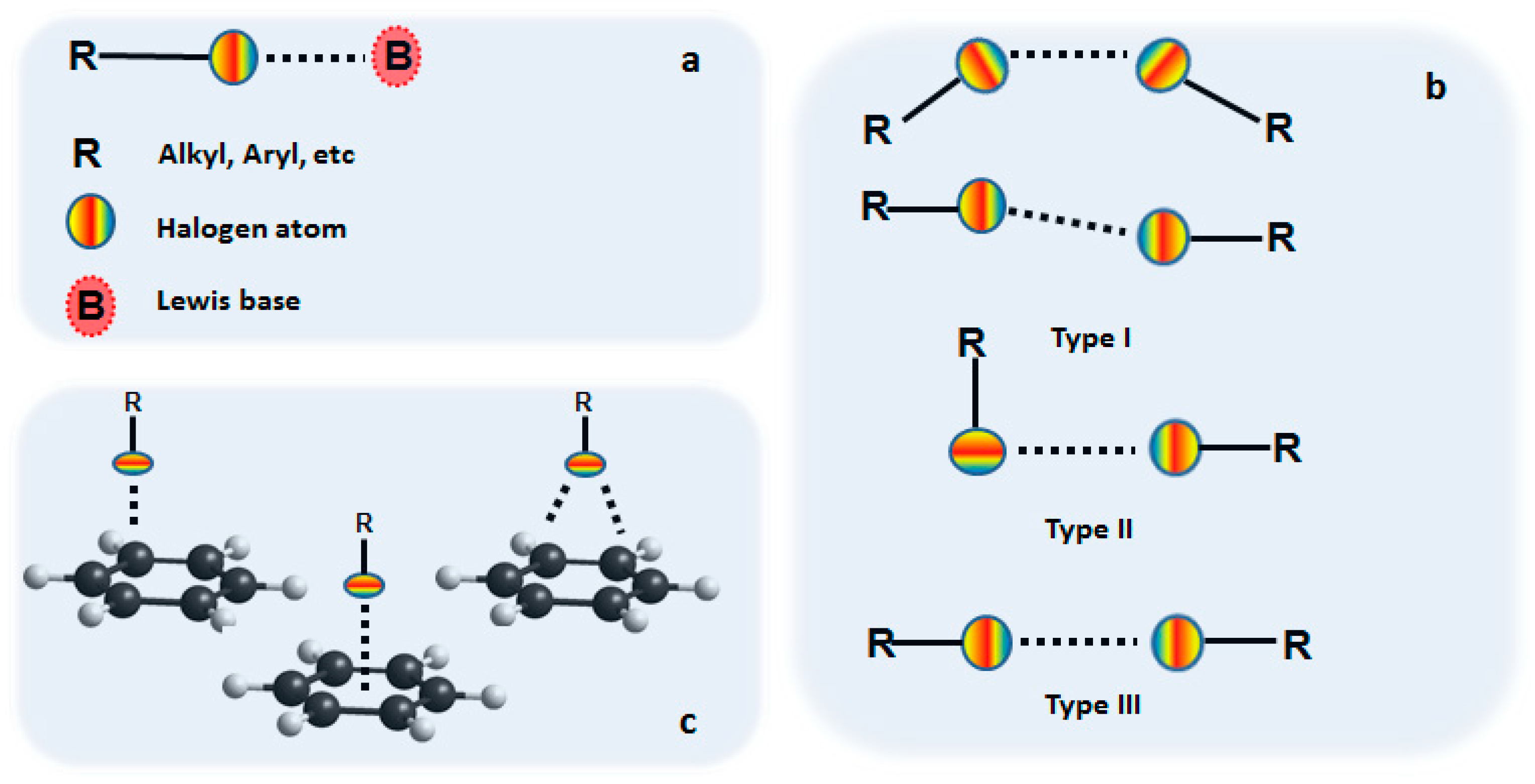
1. Introduction
2. Materials and Methods
2.1. Synthesis and Crystal Growth
2.2. X-ray Diffraction Analysis
2.3. Hirshfeld Analysis
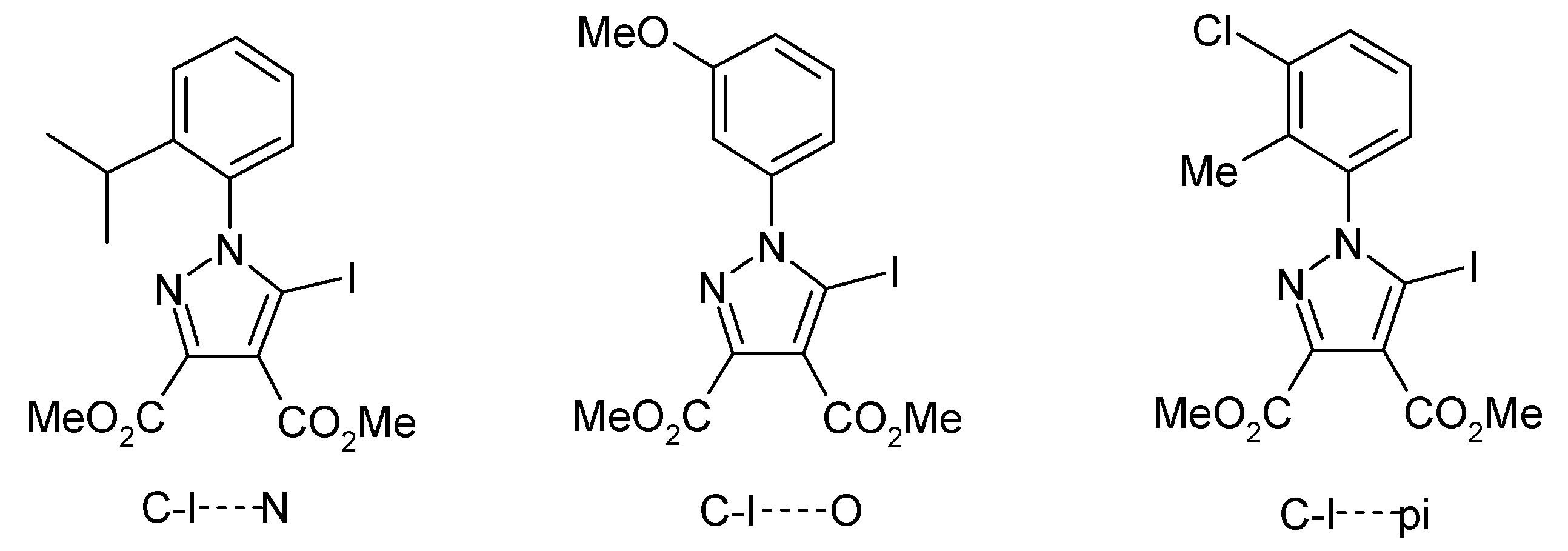
3. Results and Discussion
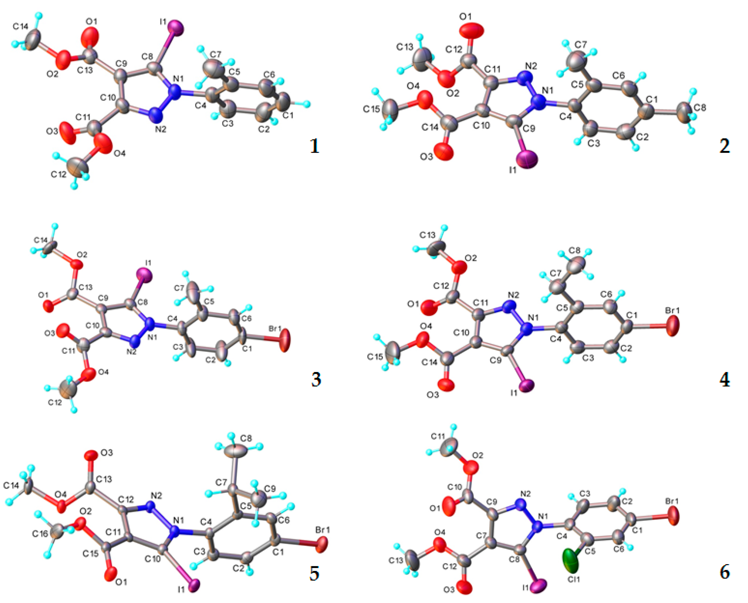
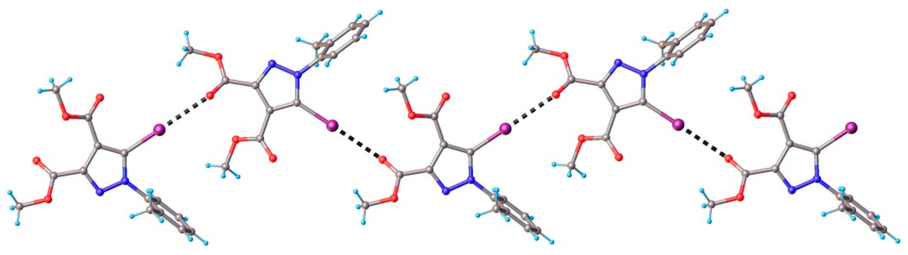
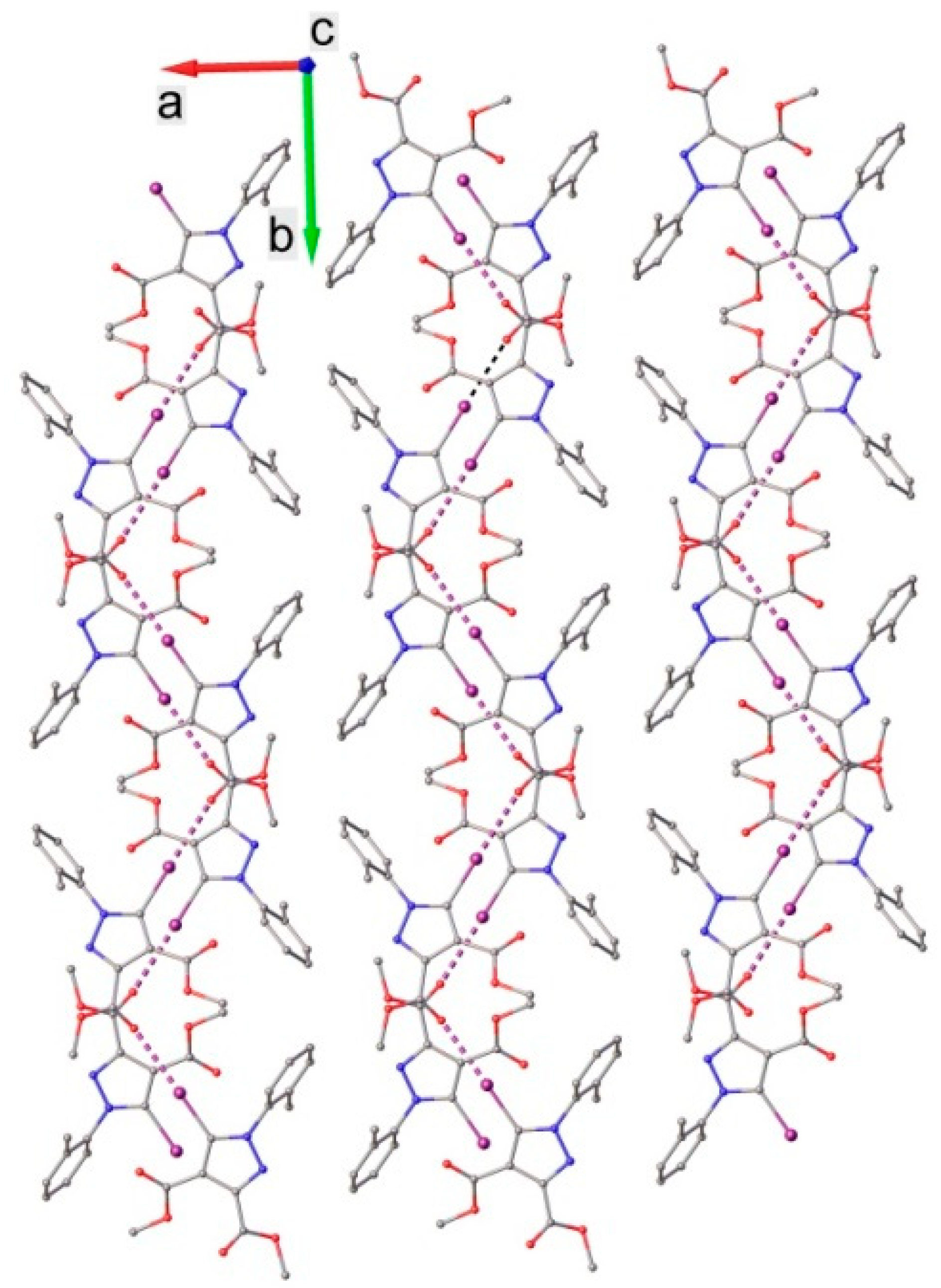
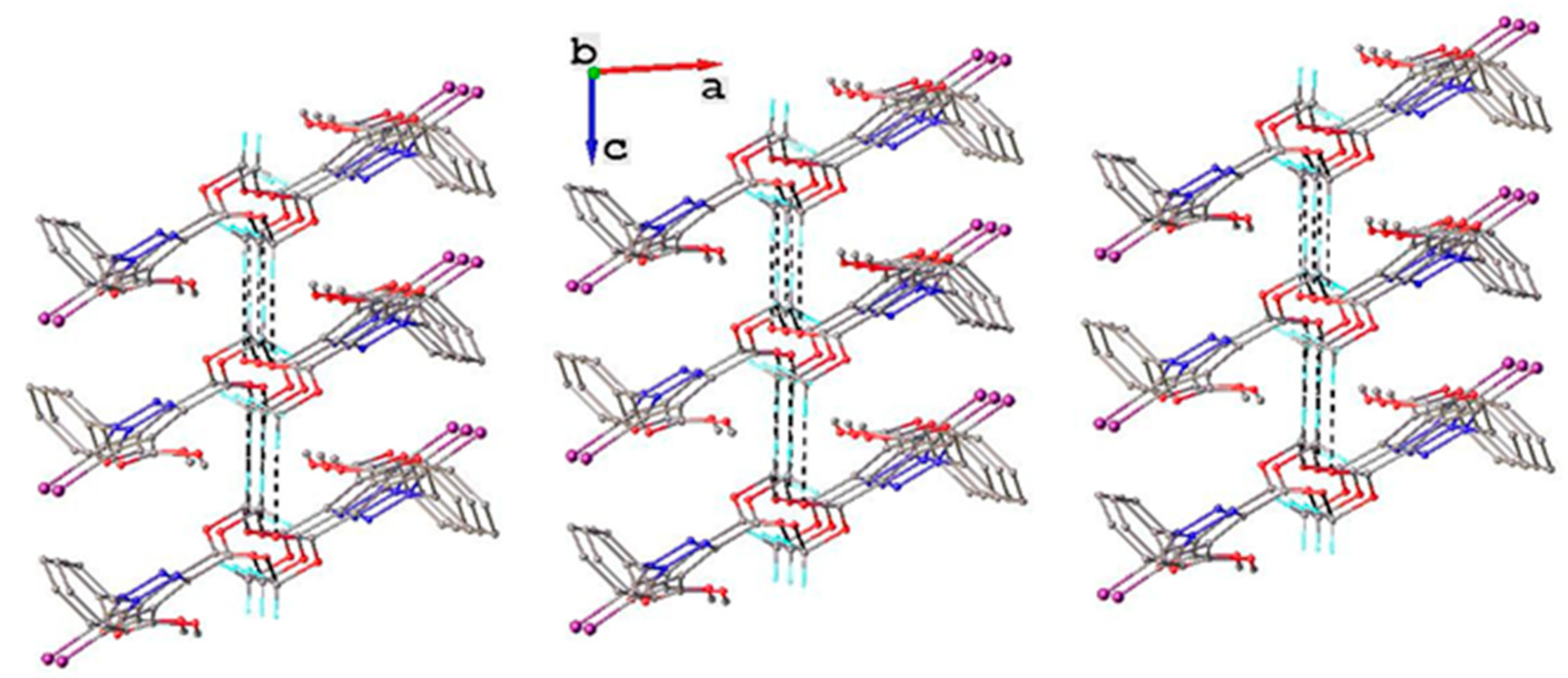
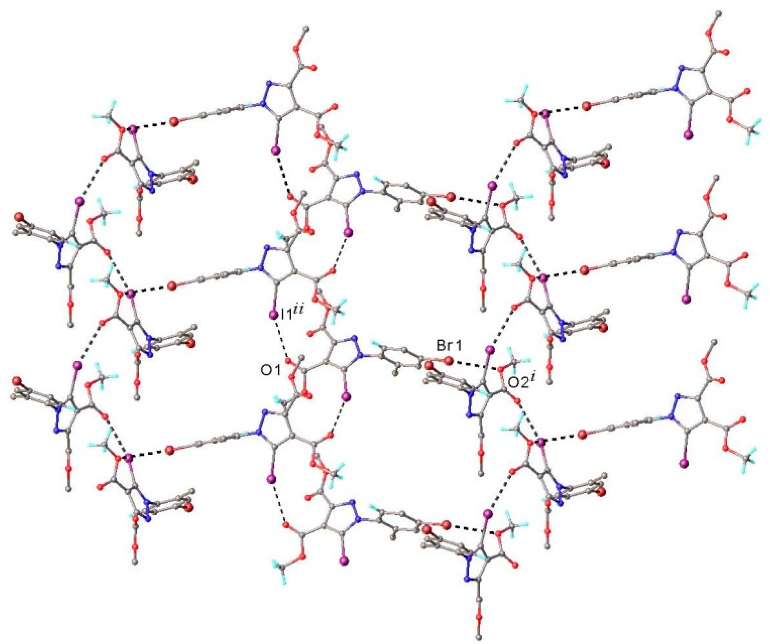
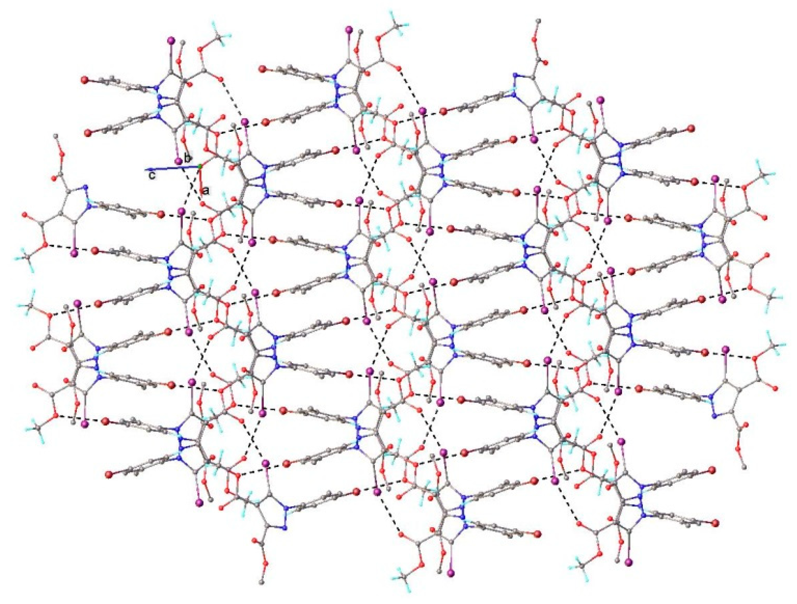
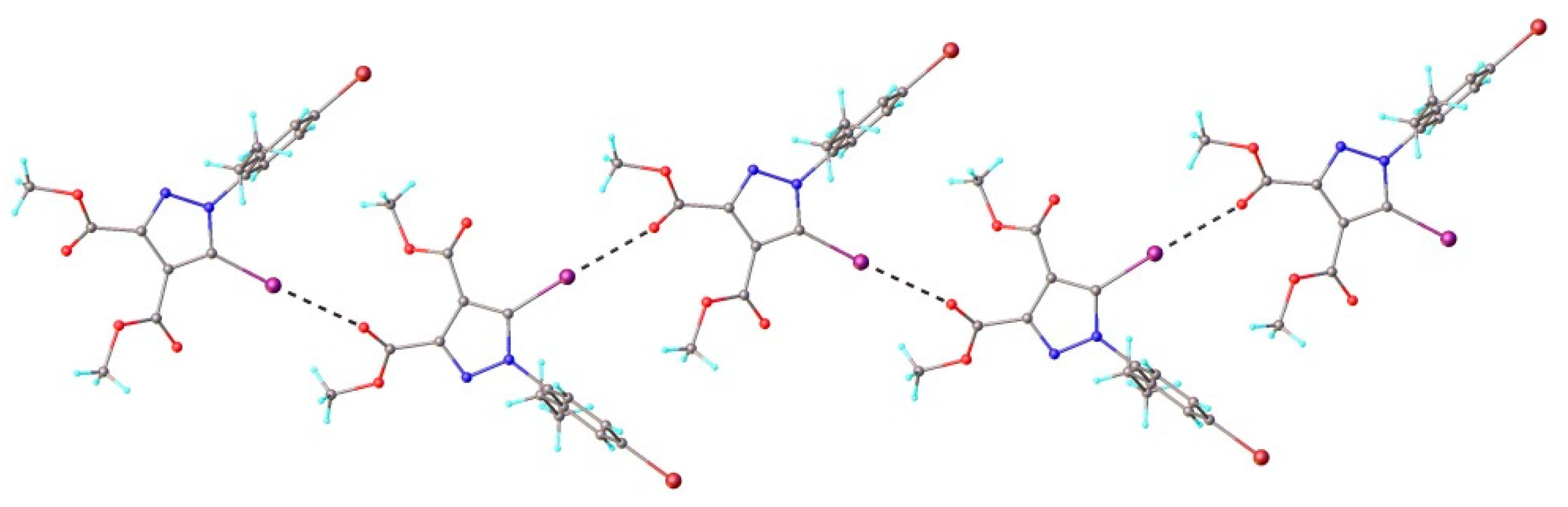
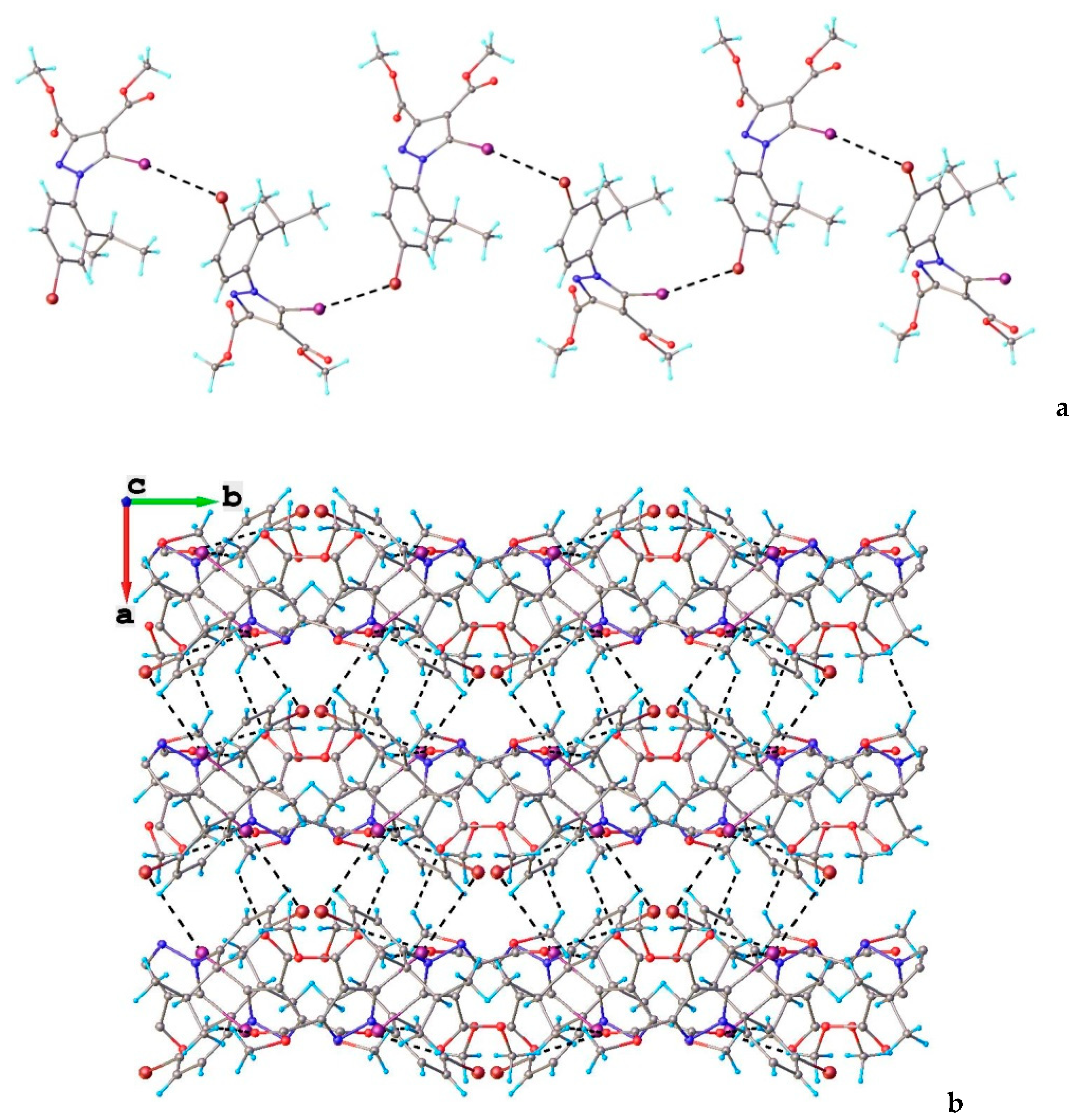
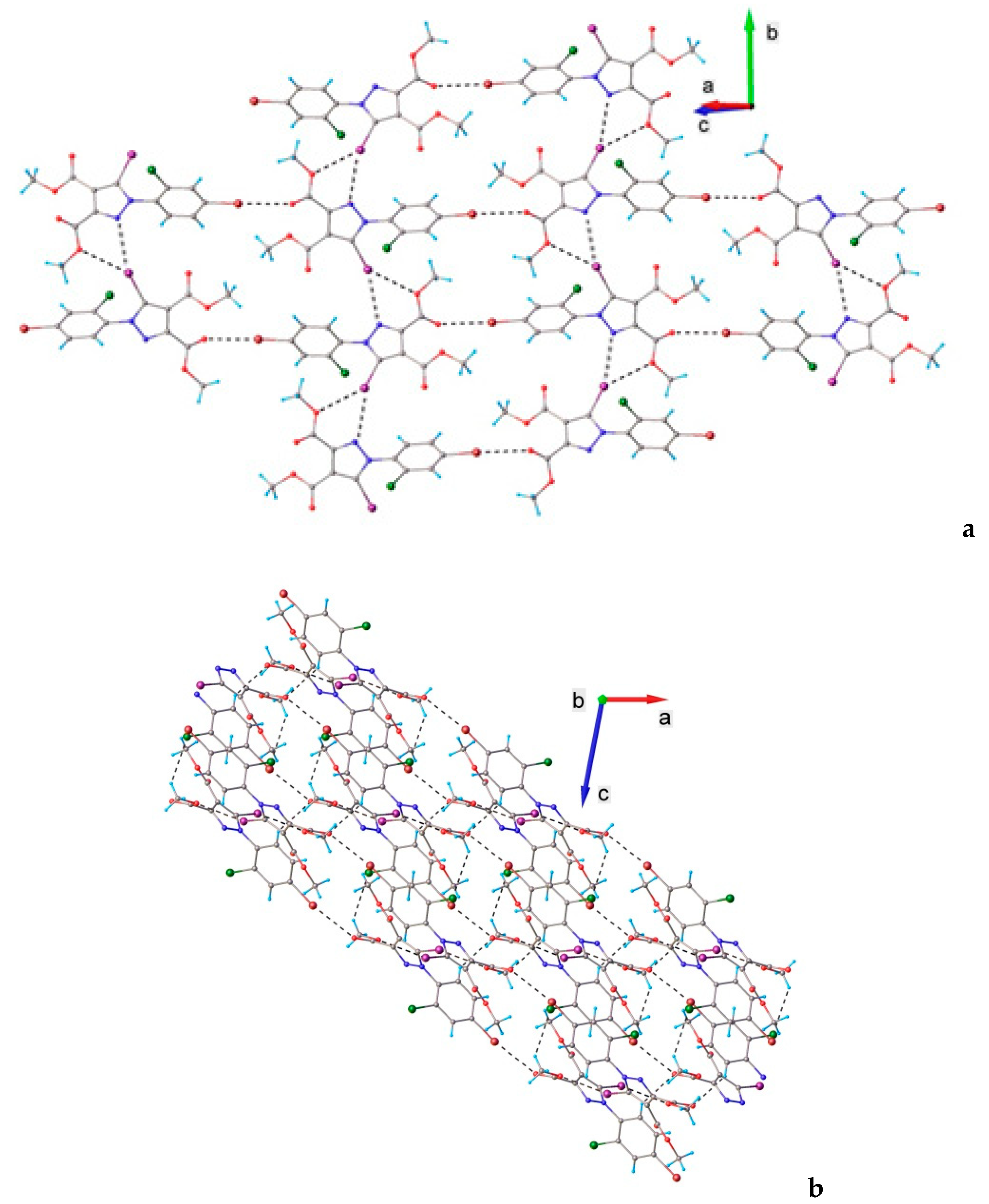
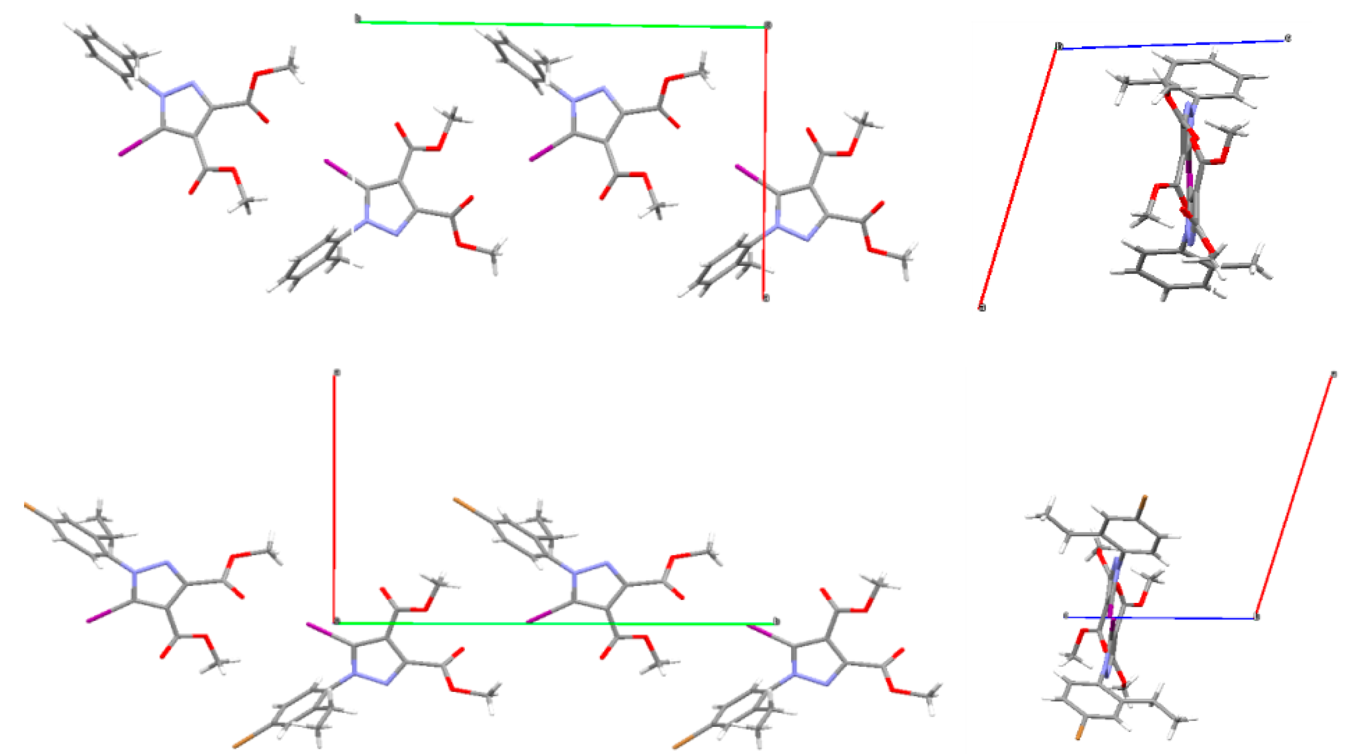
3.1. X-ray Crystallography
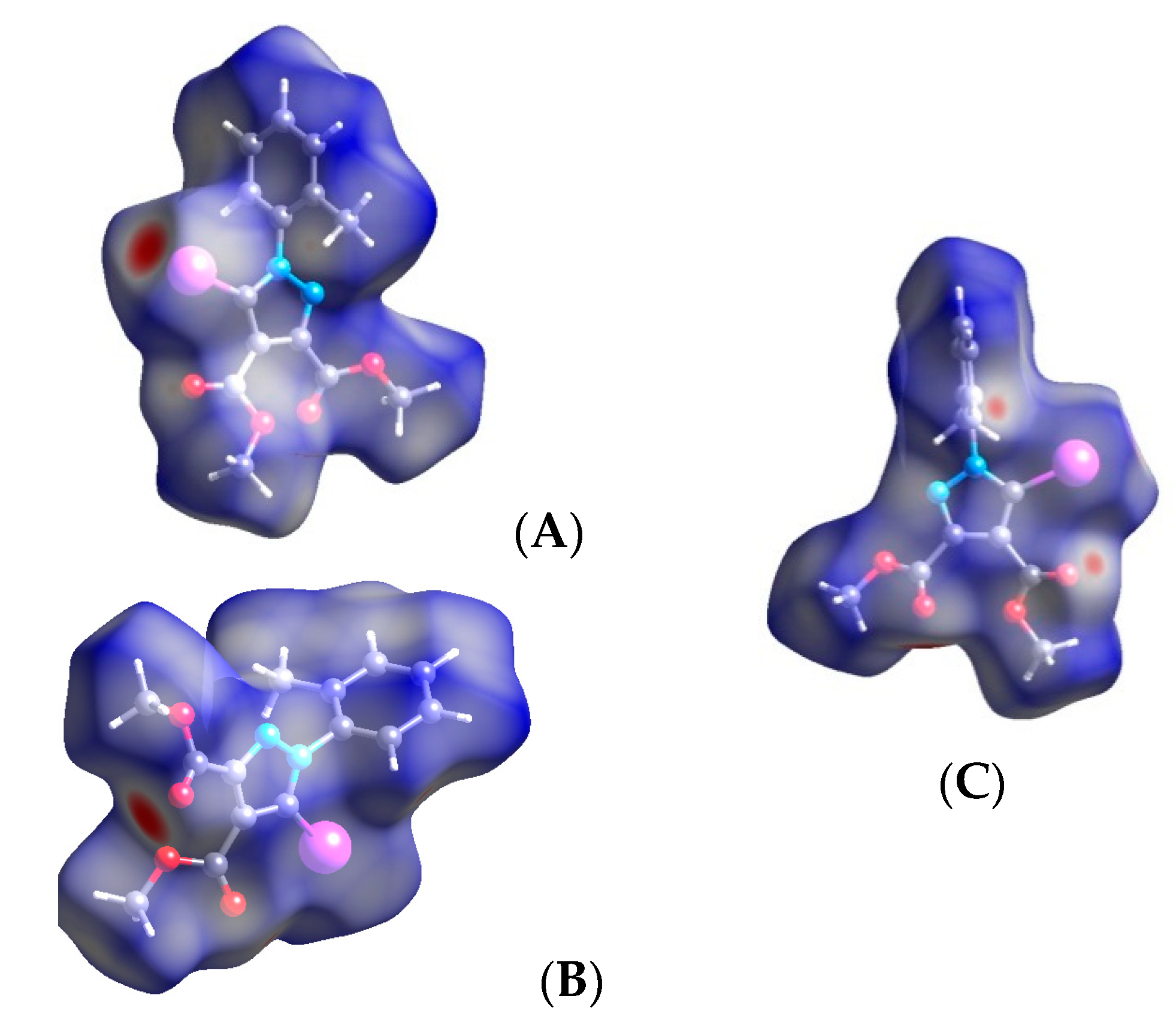
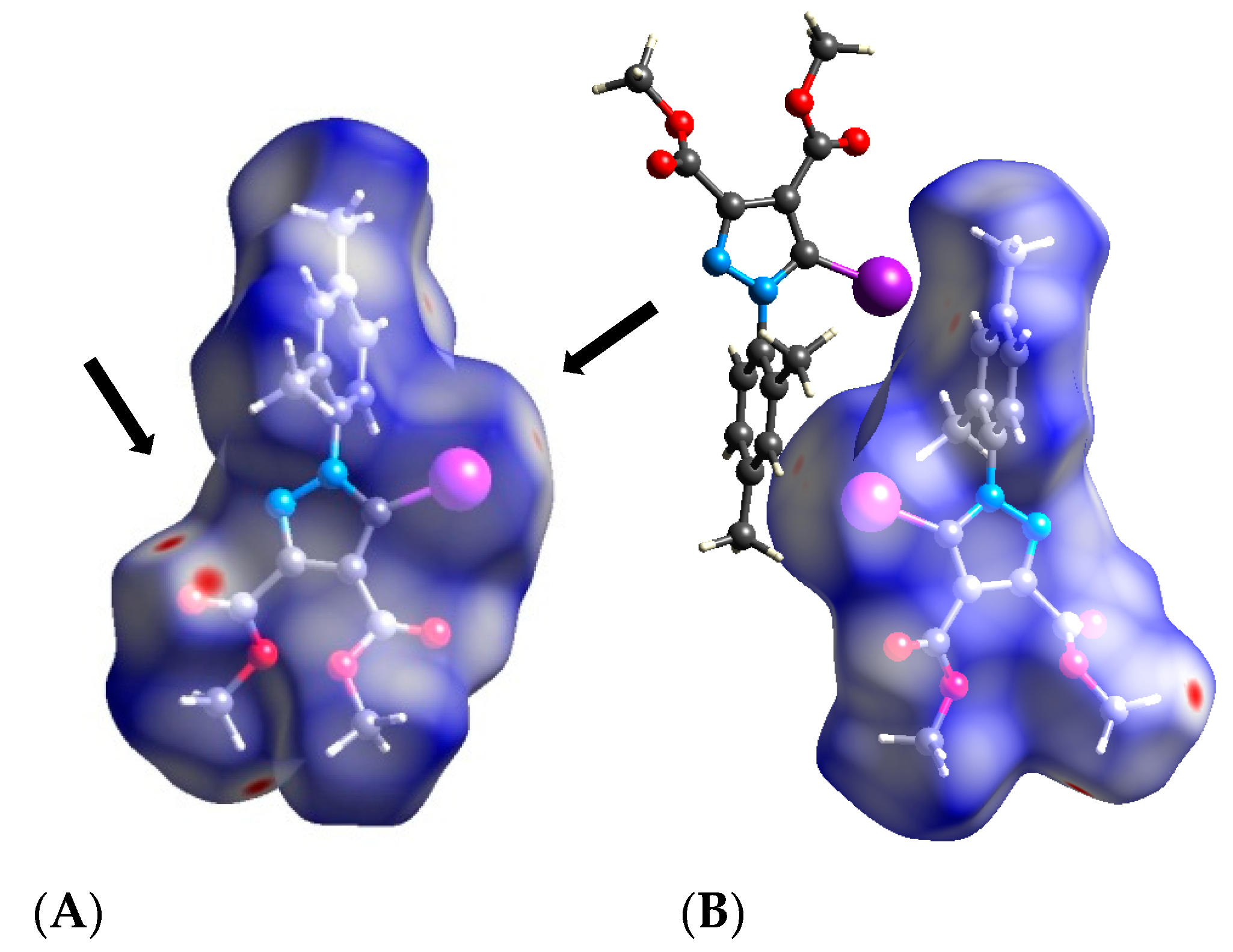
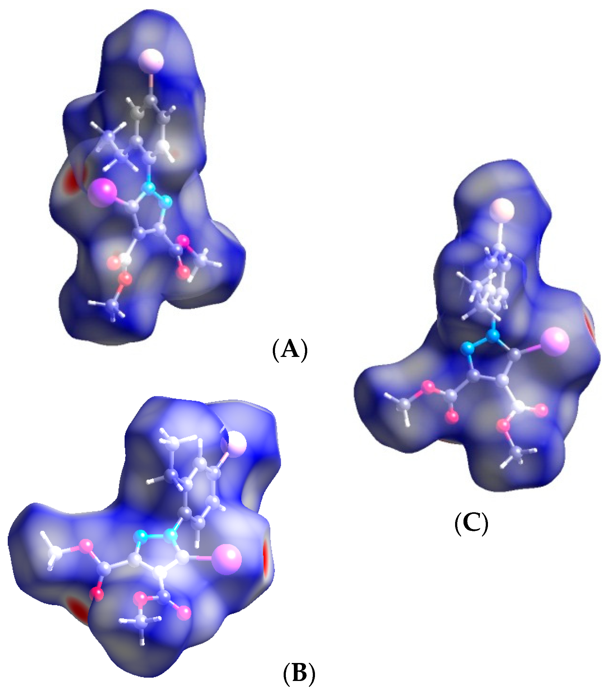
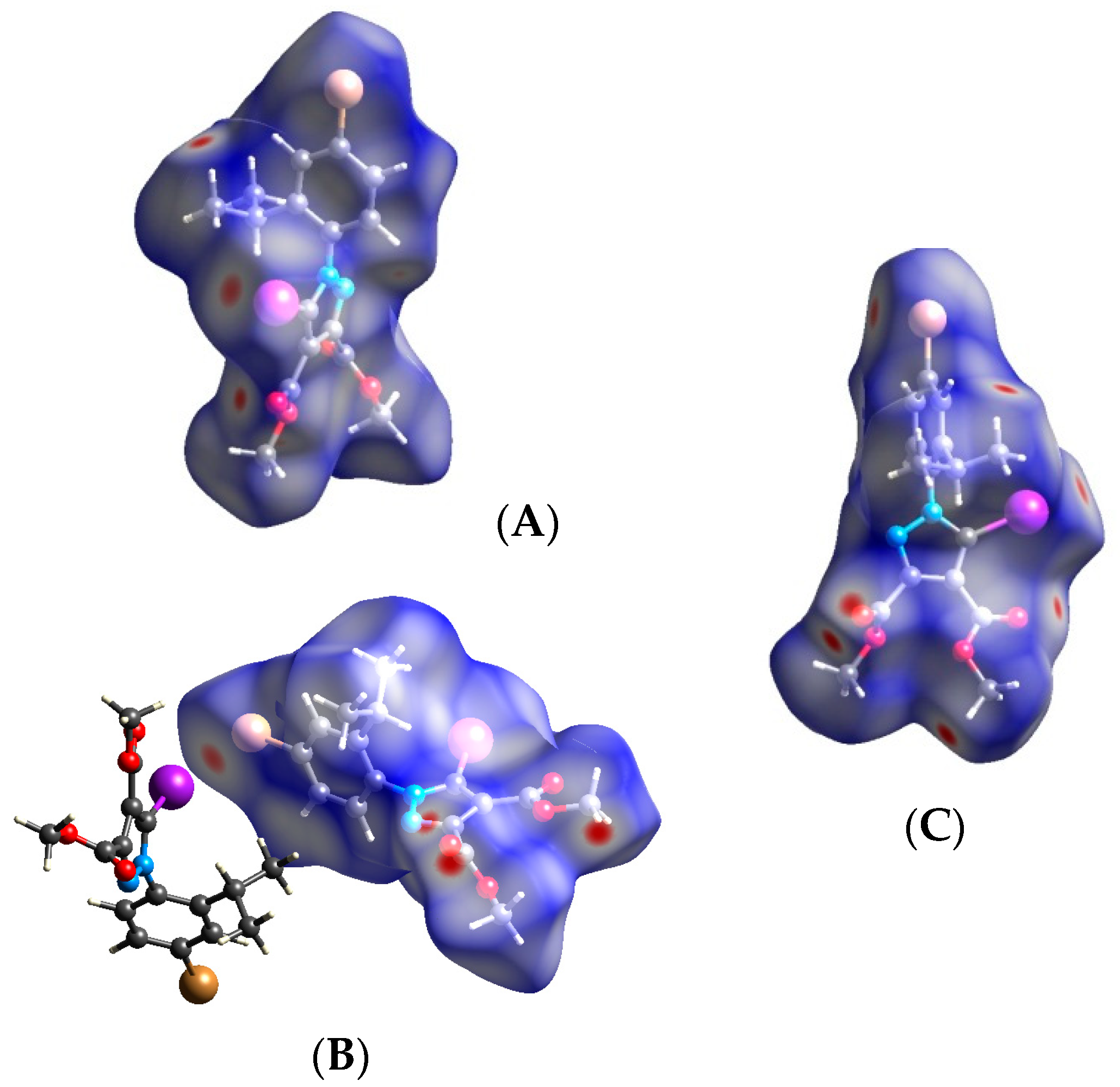
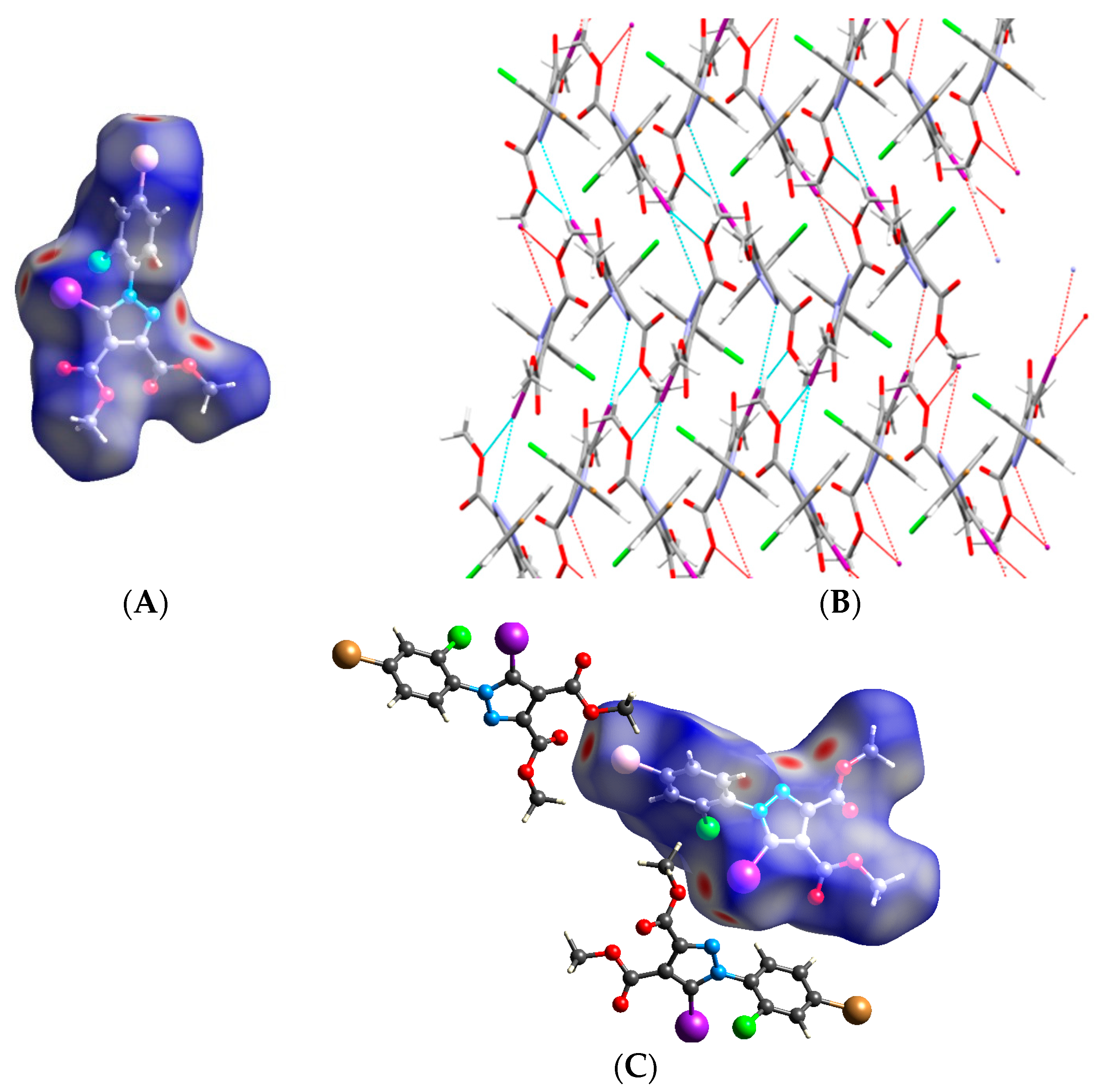
3.2. Hirshfeld Analysis
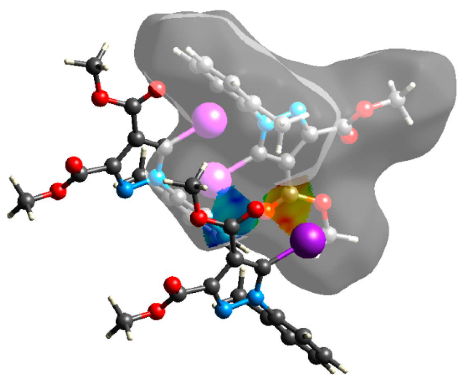
3.3. Quantum Computations
4. Conclusions
Supplementary Materials
Author Contributions
Funding
Acknowledgments
Conflicts of Interest
References
- Desiraju, G.R.; Ho, P.S.; Kloo, L.; Legon, A.C.; Marquardt, R.; Metrangolo, P.; Politzer, P.; Resnati, G.; Rissanen, K. Definition of the halogen bond (IUPAC Recommendations 2013). Pure Appl. Chem. 2013, 85, 1711–1713. [Google Scholar] [CrossRef]
- Cavallo, G.; Metrangolo, P.; Milani, R.; Pilati, T.; Priimagi, A.; Resnati, G.; Terraneo, G. The Halogen Bond. Chem. Rev. 2016, 116, 2478–2601. [Google Scholar] [CrossRef] [PubMed]
- Berger, G.; Frangville, P.; Meyer, F. Halogen bonding for molecular recognition: New developments in materials and biological sciences. Chem. Commun. 2020, 56, 4970–4981. [Google Scholar] [CrossRef] [PubMed]
- Priimagi, A.; Cavallo, G.; Metrangolo, P.; Resnati, G. The halogen bond in the design of functional supramolecular materials: Recent advances. Acc. Chem. Res. 2013, 46, 2686–2695. [Google Scholar] [CrossRef]
- Saccone, M.; Catalano, L. Halogen Bonding beyond Crystals in Materials Science. Phys. Chem. B 2019, 123, 9281–9290. [Google Scholar] [CrossRef]
- Berger, G.; Soubhyea, J.; Meyer, F. Halogen bonding in polymer science: From crystal engineering to functional supramolecular polymers and materials. Polym. Chem. 2015, 6, 3559–3580. [Google Scholar] [CrossRef]
- Ding, X.; Tuikka, M.; Haukka, M. Halogen Bonding in Crystal Engineering. In Recent Advances in Crystallography; Benedict, J.B., Ed.; IntechOpen: London, UK, 2012. [Google Scholar]
- Mukherejee, A.; Tothadi, S.; Desiraju, G.R. Halogen Bonds in Crystal Engineering: Like Hydrogen Bonds yet Different. Acc. Chem. Res. 2014, 47, 2514–2524. [Google Scholar] [CrossRef]
- Metrangolo, P.; Resnati, G. (Eds.) Halogen Bonding I: Impact on Materials Chemistry and Life Sciences; Springer: Cham, Switzerland, 2015. [Google Scholar]
- Metrangolo, P.; Resnati, G.; Pilati, T.; Biella, S. Halogen Bonding in Crystal Engineering. Structure and Bonding; Springer: Belin/Heidelberg, Germany, 2007. [Google Scholar]
- Bulfield, D.; Engelage, E.; Mancheski, L.; Stoesser, J.; Huber, S.M. Crystal Engineering with Multipoint Halogen Bonding: Double Two-Point Donors and Acceptors at Work. Eur. J. Chem. 2020, 26, 1567–1575. [Google Scholar] [CrossRef]
- Sathisaran, I.; Dalvi, S. Engineering Cocrystals of Poorly Water-Soluble Drugs to Enhance Dissolution in Aqueous Medium. Pharmaceutics 2018, 10, 108. [Google Scholar] [CrossRef]
- Bulfield, D.; Huber, S.M. Halogen Bonding in Organic Synthesis and Organocatalysis. Eur. J. Chem. 2016, 22, 14434–14450. [Google Scholar] [CrossRef]
- Sutar, R.L.; Huber, S.M. Catalysis of Organic Reactions through Halogen Bonding. ACS Catal. 2019, 9, 9622–9639. [Google Scholar] [CrossRef]
- Liu, X.; Toy, P.H. Halogen Bond-Catalyzed Povarov Reactions. Adv. Synth. Catal. 2020, 362, 3437–3441. [Google Scholar] [CrossRef]
- Tepper, R.; Schubert, U.S. Halogen Bonding in Solution: Anion Recognition, Templated Self-Assembly, and Organocatalysis. Angew. Chem. Int. Ed. 2020, 57, 6004–6016. [Google Scholar] [CrossRef] [PubMed]
- Kobayashi, Y.; Takemoto, Y. Reactions Catalyzed by 2-Halogenated Azolium Salts: From Halogen-Bond Donors to Brønsted-Acidic Salts. Synlett 2020, 31, 772–783. [Google Scholar] [CrossRef]
- Yang, H.; Wong, M.W. Application of Halogen Bonding to Organocatalysis: A Theoretical Perspective. Molecules 2020, 25, 1045. [Google Scholar] [CrossRef] [PubMed]
- Auffinger, P.; Hays, F.A.; Westhof, E.; Ho, P.S. Halogen bonds in biological molecules. Proc. Natl. Acad. Sci. USA 2004, 101, 16789–16794. [Google Scholar] [CrossRef] [PubMed]
- Lu, Y.; Wang, Y.; Zhu, W. Nonbonding interactions of organic halogens in biological systems: Implications for drug discovery and biomolecular design. Phys. Chem. Chem. Phys. 2010, 12, 4543–4551. [Google Scholar] [CrossRef]
- Wilcken, R.; Zimmermann, M.O.; Lange, A.; Joerger, A.C.; Boeckler, F.M. Principles and Applications of Halogen Bonding in Medicinal Chemistry and Chemical Biology. J. Med. Chem. 2013, 56, 1363–1388. [Google Scholar] [CrossRef]
- Scholfield, M.R.; Zanden, C.M.V.; Carter, M.; Ho, P.S. Halogen bonding (X-bonding): A biological perspective. Protein Sci. 2013, 22, 139–152. [Google Scholar] [CrossRef]
- Ho, P.S. Halogen bonding in medicinal chemistry: From observation to prediction. Future Med. Chem. 2017, 9, 637–640. [Google Scholar] [CrossRef]
- Bayse, C.A. Halogen bonding from the bonding perspective with considerations for mechanisms of thyroid hormone activation and inhibition. N. J. Chem. 2018, 42, 10623–10632. [Google Scholar] [CrossRef] [PubMed]
- Heidrich, J.; Sperl, L.E.; Boeckler, F.M. Embracing the Diversity of Halogen Bonding Motifs in Fragment-Based Drug Discovery—Construction of a Diversity-Optimized Halogen-Enriched Fragment Library. Front. Chem. 2019, 7, 9. [Google Scholar] [CrossRef] [PubMed]
- Nayak, S.K.; Terraneo, G.; Piacevoli, Q.; Bertolotti, F.; Scilabra, P.; Brown, J.T.; Rosokha, S.V.; Resnati, G. Molecular Bases for Anesthetic Agents: Halothane as a Halogen- and Hydrogen-Bond Donor. Angew. Chem. Int. Ed. 2019, 58, 12456–12459. [Google Scholar] [CrossRef] [PubMed]
- Kryukova, M.A.; Sapegin, A.V.; Novikov, A.S.; Krasavin, M.; Ivanov, D.M. New Crystal Forms for Biologically Active Compounds. Part 2: Anastrozole as N-Substituted 1,2,4-Triazole in Halogen Bonding and Lp-π Interactions with 1,4-Diiodotetrafluorobenzene. Crystals 2020, 10, 371. [Google Scholar] [CrossRef]
- Erdeley, M. Halogen bonding in solution. Chem. Soc. Rev. 2012, 41, 3547–3557. [Google Scholar] [CrossRef] [PubMed]
- Glasser, R.; Chen, N.; Wu, H.; Knotts, N.; Kaupp, M. 13C NMR Study of Halogen Bonding of Haloarenes: Measurements of Solvent Effects and Theoretical Analysis. J. Am. Chem. Soc. 2004, 126, 4412–4419. [Google Scholar] [CrossRef] [PubMed]
- Jentzsch, A.V. Applications of halogen bonding in solution. Pure Appl. Chem. 2015, 87, 15–41. [Google Scholar]
- Von der Heiden, D.; Vanderkooy, A.; Erdélyi, M. Halogen bonding in solution: NMR spectroscopic approaches. Coord. Chem. Rev. 2020, 407, 213147. [Google Scholar] [CrossRef]
- Voelkel, M.H.H.; Wonner, P.; Huber, S.M. Preorganization: A Powerful Tool in Intermolecular Halogen Bonding in Solution. ChemistryOpen 2020, 9, 214–224. [Google Scholar] [CrossRef]
- Clark, T.; Henneman, M.; Murray, J.S.; Politzer, P. Halogen bonding: The σ-hole. J. Mol. Model. 2007, 13, 291–296. [Google Scholar] [CrossRef]
- Kolár, M.H.; Hobza, P. Computer modeling of halogen bonds and other σ-hole interactions. Chem. Rev. 2016, 116, 5155–5187. [Google Scholar] [CrossRef] [PubMed]
- Wang, H.; Wang, W.; Jin, W.J. σ-Hole Bond vs π-Hole Bond: A Comparison Based on Halogen Bond. Chem. Rev. 2016, 116, 5072–5104. [Google Scholar] [CrossRef] [PubMed]
- Clark, T. Halogen bonds and σ-holes. Faraday Discuss. 2017, 203, 9–27. [Google Scholar] [CrossRef]
- Politzer, P.; Murray, J.S.; Clark, T.; Resnati, G. The sigma-hole revisited. Phys. Chem. Chem. Phys. 2017, 19, 32166–32178. [Google Scholar] [CrossRef] [PubMed]
- Breugst, M.; Koenig, J.J. σ-Hole Interactions in Catalysis. Eur. J. Org. Chem. 2020, 5473–5487. [Google Scholar] [CrossRef]
- Lim, J.Y.C.; Beer, P.D. Sigma-Hole Interactions in Anion Recognition. Chem 2018, 4, 731–783. [Google Scholar] [CrossRef]
- Murray, J.S.; Politzer, P. Interaction and Polarization Energy Relationships in σ-Hole and π-Hole Bonding. Crystals 2020, 10, 76. [Google Scholar] [CrossRef]
- Pancholi, J.; Beer, P.D. Halogen bonding motifs for anion recognition. Coord. Chem. Rev. 2020, 416, 213281. [Google Scholar] [CrossRef]
- Metrangolo, P.; Resnati, G. Type II halogen—Halogen contacts are halogen bonds. IUCrJ 2014, 1, 5–7. [Google Scholar] [CrossRef]
- Ibrahim, M.A.A.; Moussa, N.A.M. Unconventional Type III Halogen⋯Halogen Interactions: A Quantum Mechanical Elucidation of σ-Hole⋯σ-Hole and Di-σ-Hole Interactions. ACS Omega 2020, 5, 21824–21835. [Google Scholar] [CrossRef]
- Draghici, C.; Caira, M.R.; Dumitrescu, D.E.; Dumitrascu, F. Halogen Bonds of 4-Iodosydnones in Solution Deduced from 13C-NMR Spectra. Rev. Chim. 2018, 69, 843–846. [Google Scholar] [CrossRef]
- Popa, M.M.; Shova, S.; Hrubaru, M.; Barbu, L.; Draghici, C.; Dumitrascu, F.; Dumitrescu, D.E. Introducing chirality in halogenated 3-arylsydnones and corresponding 1-arylpyrazoles obtained by 1,3-dipolar cycloaddition. RSC Adv. 2020, 10, 15656–15664. [Google Scholar] [CrossRef]
- Popa, M.M.; Man, I.C.; Draghici, C.; Shova, S.; Caira, M.R.; Dumitrascu, F.; Dumitrescu, D. Halogen bonding in 5-iodo-1-arylpyrazoles investigated in the solid state and predicted by solution 13C-NMR spectroscopy. CrystEngComm 2019, 21, 7085–7093. [Google Scholar] [CrossRef]
- Dumitrascu, F.; Draghici, C.; Dumitrescu, D.; Tarko, L.; Raileanu, D. Direct iodination of sydnones and their cycloadditions to form 5-iodopyrazoles. Liebigs Ann. Recl. 1997, 1997, 2613–2616. [Google Scholar] [CrossRef]
- Dumitrascu, F.; Mitan, I.C.; Dumitrescu, D.; Drăghici, C.; Caproiu, M.T. Steric effects on the sydnones reactivity. New sydnones and pyrazoles. Arkivoc 2002, 2, 80–86. [Google Scholar] [CrossRef]
- Dumitrascu, F.; Draghici, C.; Crangus, C.; Caproiu, M.T.; Mitan, C.I.; Dumitrescu, D.; Raileanu, D. Atropisomerism of new sterically hindered 1-arylpyrazoles. Rev. Roum. Chim. 2002, 47, 315–318. [Google Scholar] [CrossRef]
- Dumitrascu, F.; Draghici, C.; Caproiu, M.T.; Crangus, C.; Mitan, C.I.; Barbu, L. Steric effects in the direct iodination and 1,3 dipolar cycloaddition of sydnones. Rev. Chim. (Bucharest) 2001, 52, 183–187. [Google Scholar]
- CrysAlisPro Software System, Version 1.171.38.46; Oxford Diffraction Ltd., Rigaku Corporation: Oxford, UK, 2015.
- Dolomanov, O.V.; Bourhis, L.J.; Gildea, R.J.; Howard, J.A.K.; Puschmann, H.J. OLEX2: A complete structure solution, refinement and analysis program. Appl. Cryst. 2009, 42, 339–341. [Google Scholar] [CrossRef]
- Sheldrick, G. SHELXT-Integrated space-group and crystal-structure determination. Acta Cryst. A 2015, 71, 3–8. [Google Scholar] [CrossRef]
- Sheldrick, G. Crystal structure refinement with SHELXL. Acta Cryst. C 2015, 71, 3–8. [Google Scholar] [CrossRef]
- Wolff, S.K.; Grimwood, D.J.; McKinnon, J.J.; Turner, M.J.; Jayatilaka, D.; Spackman, M.A. (Eds.) CrystalExplorer, Version 3.1; University of Western Australia: Crawley, Australia, 2012. [Google Scholar]
- Spackman, M.A.; Jayatilaka, D. Hirshfeld surface analysis. CrystEngComm 2009, 11, 19–32. [Google Scholar] [CrossRef]
- Chevallier, F.; Halauko, Y.S.; Pecceu, C.; Nassar, I.; Dam, T.U.; Roisnel, T.; Matulis, V.E.; Ivashkevich, O.A.; Mongin, F. N-aryl pyrazoles: DFT calculations of CH acidity and deprotonative metallation using a combination of lithium and zinc amides. Org. Biomol. Chem. 2011, 9, 4671–4684. [Google Scholar] [CrossRef] [PubMed]
- Bondi, A. van der Waals Volumes and Radii. J. Phys. Chem. 1964, 68, 441–451. [Google Scholar] [CrossRef]
- Frisch, M.J.; Trucks, G.W.; Schlegel, H.B.; Scuseria, G.E.; Robb, M.; Cheeseman, J.; Scalmani, G.; Barone, V.; Mennucci, B.; Petersson, G.; et al. Gaussian 09, Revision C.01; Gaussian, Inc.: Wallingford, CT, USA, 2009. [Google Scholar]
- Becke, A.D. Density-functional thermochemistry. III. The role of exact exchange. J. Chem. Phys. 1993, 98, 5648–5652. [Google Scholar] [CrossRef]
- Lee, C.; Yang, W.; Parr, R.G. Development of the Colle-Salvetti correlation-energy formula into a functional of the electron density. Phys. Rev. B 1988, 37, 785–789. [Google Scholar] [CrossRef] [PubMed]
- Grimme, S.; Antony, J.; Ehrlich, S.; Krieg, H. A consistent and accurate ab initio parametrization of density functional dispersion correction (DFT-D) for the 94 elements H-Pu. J. Chem. Phys. 2010, 132, 154104. [Google Scholar] [CrossRef]
- Godbout, N.; Salahub, D.R.; Andzelm, J.; Wimmer, E. Optimization of Gaussian-type basis sets for local spin density functional calculations. Part I. Boron through neon, optimization technique and validation. Can. J. Chem. 1992, 70, 560–571. [Google Scholar] [CrossRef]
- Weigend, F.; Ahlrichs, R. Balanced basis sets of split valence, triple zeta valence and quadruple zeta valence quality for H to Rn: Design and assessment of accuracy. Phys. Chem. Chem. Phys. 2005, 7, 3297–3305. [Google Scholar] [CrossRef]
- Nwachukwu, C.I.; Bowling, N.P.; Bosch, E. C—I⋯N and C—I⋯π halogen bonding in the structures of 1-benzyliodoimidazole derivatives. Acta Crystallogr. Sect. C Struct. Chem. 2017, 73, 2–8. [Google Scholar] [CrossRef]


| Compound |  |  |  | |
| X-ray Parameters | ||||
| 1 | 2 | 3 | ||
| Empirical formula | C14H13IN2O4 | C15H15IN2O4 | C14H12BrIN2O4 | |
| Fw | 400.16 | 414.19 | 479.07 | |
| T [K] | 293(2) | 293(2) | 281(2) | |
| space group | P21/c | P21/c | Pbca | |
| a [Å] | 11.9709(13) | 15.0655(10) | 10.3287(8) | |
| b [Å] | 16.994(2) | 11.2635(11) | 15.3048(12) | |
| c [Å] | 7.8913(11) | 9.7028(8) | 21.492(2) | |
| α [°] | 90 | 90 | 90 | |
| β [°] | 105.461(14) | 92.930(7) | 90 | |
| γ [°] | 90 | 90 | 90 | |
| V [Å3] | 1547.3(4) | 1644.3(2) | 3397.4(5) | |
| Z | 4 | 4 | 8 | |
| ρcalcd [g cm−3] | 1.718 | 1.673 | 1.873 | |
| μ [mm−1] | 2.086 | 1.966 | 4.255 | |
| Crystal size [mm] | 0.30 × 0.25 × 0.15 | 0.30 × 0.05 × 0.03 | 0.35 × 0.25 × 0.25 | |
| 2Θ range [°] | 4.268 to 50.054 | 4.518 to 50.052 | 3.79 to 50.048 | |
| Reflections collected | 8831 | 7765 | 8816 | |
| Independent reflections | 2727[Rint = 0.0260] | 2904[Rint = 0.0468] | 2996[Rint = 0.0615] | |
| Data/restraints/parameters | 2727/0/193 | 2904/0/199 | 2996/0/202 | |
| GOF c | 1.095 | 1.083 | 1.028 | |
| R1a | 0.0317 | 0.0602 | 0.0534 | |
| wR2b | 0.0592 | 0.0856 | 0.1256 | |
| Largest diff. peak/hole [e Å−3] | 0.34/−0.27 | 0.54/−0.57 | 0.79/−1.2 | |
| CCDC number | 2039133 | 2039134 | 2039135 | |
| Compound |  |  |  | |
| X-ray Parameters | ||||
| 4 | 5 | 6 | ||
| Empirical formula | C15H14BrIN2O4 | C16H16BrIN2O4 | C13H9BrClIN2O4 | |
| Fw | 493.09 | 507.12 | 499.48 | |
| T [K] | 293(2) | 200(2) | 295(2) | |
| space group | P21/c | Pbca | P21/n | |
| a [Å] | 12.5205(14) | 13.9777(5) | 8.0519(6) | |
| b [Å] | 17.3525(12) | 12.2682(5) | 13.4135(7) | |
| c [Å] | 8.2809(10) | 21.0409(9) | 16.0842(12) | |
| α [°] | 90 | 90 | 90 | |
| β [°] | 104.962(11) | 90 | 100.835(8) | |
| γ [°] | 90 | 90 | 90 | |
| V [Å3] | 1738.1(3) | 3608.1(3) | 1706.2(2) | |
| Z | 4 | 8 | 4 | |
| ρcalcd [g cm−3] | 1.884 | 1.867 | 1.944 | |
| μ [mm−1] | 4.161 | 4.012 | 4.392 | |
| Crystal size [mm] | 0.30 × 0.15 × 0.10 | 0.30 × 0.20 × 0.15 | 0.30 × 0.25 × 0.20 | |
| 2Θ range [°] | 3.368 to 50.048 | 4.824 to 50.046 | 3.984 to 50.054 | |
| Reflections collected | 7071 | 11745 | 6546 | |
| Independent reflections | 3064 [Rint = 0.0433] | 3185 [Rint = 0.0389] | 3011 [Rint = 0.0592] | |
| Data/restraints/parameters | 3064/0/211 | 3185/0/221 | 3011/0/201 | |
| GOF c | 1.013 | 1.075 | 1.029 | |
| R1a | 0.0462 | 0.0312 | 0.0556 | |
| wR2b | 0.0896 | 0.0668 | 0.1310 | |
| Largest diff. peak/hole [e Å−3] | 0.39/−0.67 | 0.37/−0.61 | 0.45/−0.98 | |
| CCDC number | 2039136 | 2039137 | 2039138 | |
 |  |  |
| 1 | 2 | 3 |
 |  |  |
| 4 | 5 | 6 |
 | ||
| Front view of I atom along I-C bond |  |  |  |
| Vs,max = 99.75 kJ/mol | Vs,max = 98.44 kJ/mol | Vs,max = 122.05 kJ/mol | |
| Front view of Br atom along Br-C bond | - | - |  |
| 1 | 2 | 3 Vs,max = 55.13 kJ/mol | |
| Front view of I atom along I-C bond |  |  |  |
| 4 Vs,max = 115.6 kJ/mol | 5 Vs,max = 114.19 kJ/mol | 6 Vs,max = 111.56 kJ/mol | |
| Front view of Br atom along Br-C bond |  |  |  |
| 4 Vs,max = 48.56 eV | 5 Vs,max = 48.56 kJ/mol | 6 Vs,max = 69.56 kJ/mol |
 |  |
| 1-1 −31.49 kJ/mol | 2-1 −36.11 kJ/mole/dimer (−18.05 kJ/mol/I⋯π interaction) |
 |  |
| 3-1 −39.34 kJ/mol | 3-2 −19.31 kJ/mol |
 |  |
| 4-1 −32.31 kJ/mol | 5-1 −18.96 kJ/mol |
 |  |
| 6-1 −43.14 kJ/mol | 6-2 −13.63 kJ/mol |
Publisher’s Note: MDPI stays neutral with regard to jurisdictional claims in published maps and institutional affiliations. |
© 2020 by the authors. Licensee MDPI, Basel, Switzerland. This article is an open access article distributed under the terms and conditions of the Creative Commons Attribution (CC BY) license (http://creativecommons.org/licenses/by/4.0/).
Share and Cite
Dumitrescu, D.; Shova, S.; Man, I.C.; Caira, M.R.; Popa, M.M.; Dumitrascu, F. 5-Iodo-1-Arylpyrazoles as Potential Benchmarks for Investigating the Tuning of the Halogen Bonding. Crystals 2020, 10, 1149. https://doi.org/10.3390/cryst10121149
Dumitrescu D, Shova S, Man IC, Caira MR, Popa MM, Dumitrascu F. 5-Iodo-1-Arylpyrazoles as Potential Benchmarks for Investigating the Tuning of the Halogen Bonding. Crystals. 2020; 10(12):1149. https://doi.org/10.3390/cryst10121149
Chicago/Turabian StyleDumitrescu, Denisa, Sergiu Shova, Isabela C. Man, Mino R. Caira, Marcel Mirel Popa, and Florea Dumitrascu. 2020. "5-Iodo-1-Arylpyrazoles as Potential Benchmarks for Investigating the Tuning of the Halogen Bonding" Crystals 10, no. 12: 1149. https://doi.org/10.3390/cryst10121149
APA StyleDumitrescu, D., Shova, S., Man, I. C., Caira, M. R., Popa, M. M., & Dumitrascu, F. (2020). 5-Iodo-1-Arylpyrazoles as Potential Benchmarks for Investigating the Tuning of the Halogen Bonding. Crystals, 10(12), 1149. https://doi.org/10.3390/cryst10121149