Abstract
The characteristics of a tunable Stokes laser based on the cascaded stimulated polariton scattering and stimulated Raman scattering in KTiOPO4 crystal were studied experimentally and theoretically. When the pumping wavelength was 1064 nm, the Stokes laser output wavelength was able to be tuned discontinuously from 1112.08 nm to 1113.64 nm, from 1114.94 nm to 1115.77 nm, and from 1117.37 nm to 1119.92 nm, and the maximum output power appeared at 1118.86 nm. With a pulse repetition frequency of 7 kHz and a pump power of 6.0 W, the maximum output power of the Stokes laser reached 734 mW, and the corresponding diode to laser conversion efficiency was 12.2%. The rate equations describing the temporal evolutions of the fundamental and Stokes waves by noncollinear stimulated polariton scattering and the Stokes wave by collinear stimulated Raman scattering were derived. They were used to simulate the tunable Stokes laser. The calculated results were in agreement with the experimental results on the whole.
1. Introduction
KTiOPO4 (KTP) is an excellent nonlinear crystal. It has many outstanding properties, such as broad high transparency in visible and near-infrared regions, reliable chemical and mechanical stability, high laser-induced damage threshold [1,2], and large nonlinear coefficient [3]. Based on its second-order nonlinear effect, it has been widely used in frequency doubling [4,5], sum-frequency mixing [6,7,8], and optical parametric oscillation [9,10,11]. Based on its stimulated Raman scattering (SRS), many Raman lasers have been developed [12,13,14].
Stimulated polariton scattering (SPS) is an efficient frequency down-conversion effect, which contains both the second-order and third-order nonlinear optical effects [15]. It will occur when a crystal with both infrared and Raman activities is pumped by a strong pumping laser beam, parametrically generating a terahertz (THz) wave and a red-shifted wave called Stokes wave [16] through noncollinear phase-matching. The frequencies of the THz and Stokes waves can be tuned by adjusting the phase-matching angle [17,18,19,20,21,22,23]. KTP is one of the few crystals, which has an SPS effect. In 2014, Wang reported a terahertz parametric source by using the SPS effect in KTP crystal [24]. More terahertz parametric sources using KTP crystal with different pump laser wavelengths and laser structures were reported later [22,25,26]. Jiang reported a Stokes laser based on SPS effect using KTP crystal, and the Stokes laser was able to be tuned from 1077.0 nm to 1080.7 nm, from 1081.3 nm to 1082.6 nm, from 1084.0 nm to 1085.3 nm, and from 1087.2 nm to 1090.6 nm [27].
In order to expand the available laser output spectrum, two different nonlinear effects are frequently used at the same time [17,28,29,30]. For instance, second harmonic generation and SRS are combined to generate 540 nm and 565 nm laser outputs [28], and sum-frequency mixing and SRS are combined to generate lasers in the visible and near-infrared regions [29]. By intracavity frequency doubling of the SPS Stokes laser using KTiOAsO4 crystal, laser outputs discontinuously tunable from 539.0 to 539.5 nm, from 540.1 to 540.4 nm, from 541.3 to 541.8 nm, from 542.7 to 542.9 nm are obtained [30]. By using the cascaded SPS and SRS effects in RbTiOPO4 crystal, the obtained Stokes laser wavelengths could be tuned from 1107.7 to 1108.1 nm, from 1109.0 to 1112.7 nm, from 1114.3 to 1115.1 nm, and from 1117.8 to 1121.1 nm [17].
In this paper, the tunable Stokes laser characteristics using the cascaded SPS and SRS effects in KTP crystal were investigated. In the second section, the experimental setup and results are presented. The fundamental frequency laser was a diode-pumped Q-switched 1064 nm Nd:YAG laser. The KTP crystal was installed in the fundamental frequency laser cavity. By using the SPS effect and adjusting the angle between the axes of the fundamental frequency laser cavity and the Stokes laser cavity, tunable Stokes laser (named as SPS-Stokes wave) could be obtained through noncollinear phase-matching. The SPS-Stokes wave was further employed as the collinear pump source of the cascaded SRS process in the same KTP crystal and the same cavity, and the tunable Raman laser (named as SRS-Stokes wave) was obtained. The presented experimental results included the pulse evolutions for the fundamental, SPS-Stokes, and SRS-Stokes waves and the tuning characteristic and the input-output characteristic. In the third section, by combining the coupled wave equations of the SPS and SRS processes and substituting them into the evolution equations of the fundamental, SPS-Stokes, and SRS-Stokes waves, the rate equations describing the temporal evolutions of the inversion population density and the photon densities of the three waves were obtained. The simulation based on these rate equations was conducted, and the results were compared with the experimental results. The last section is the conclusion.
2. Experiment and Results
The optical scheme of the Q-switched intracavity SPS-SRS laser based on KTP is illustrated in Figure 1. The fundamental wave cavity was composed of M1 and M2, while the SPS-Stokes and SRS-Stokes waves resonated in the Stokes cavity (M3 and M4). The external angle (θe) between the axes of the two cavities, which determines the phase-matching angle, could be adjusted by rotating the Stokes cavity.
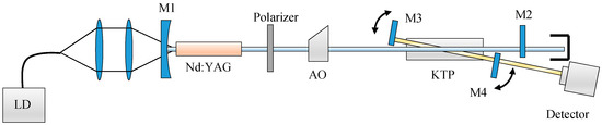
Figure 1.
Optical scheme of the Q-switched intracavity SPS-SRS laser based on KTP. LD: laser diode; AO: acousto-optic; KTP: KTiOPO4.
The laser gain medium was an anti-reflection coated Nd:YAG crystal (1 mm in diameter and 5 mm in length), which was pumped by a fiber-coupled laser diode (λ = 808 nm). An acousto-optic (AO) module was deployed as the Q switch. A polarizer was inserted in the cavity to maintain the laser polarization parallel to the z-axis of the KTP crystal. The rear mirror M1 had a curvature radius of 3000 mm, and it was coated for high reflection (HR) at 1064 nm (R > 99.9%) and high transmission (HT) at 808 nm. M2 was a flat mirror and coated for HR at 1064 nm (R > 99.2%). The length of the fundamental cavity was about 30 cm. The Stokes cavity contained two flat mirrors, M3 and M4, which were mounted on a rotating platform in order to control the phase-matching angle. M3 was coated for HR in the spectral range of 1060–1200 nm (R > 99.9%), while the output coupler M4 was coated for HR in the spectral range of 1060–1090 nm (R > 99.1%) and partial transmission in the range of 1110–1120 nm (R = 89.9% at 1118 nm). The length of the Stokes cavity was 8.0 cm. The KTP crystal (5 × 5 × 35 mm3) was cut in the x-direction, and the anti-reflection was coated on both ends, and the scattering configuration was X(ZZ)X.
Figure 2 shows the pulse evolutions for the fundamental, SPS-Stokes, and SRS-Stokes waves. They were obtained when the pump power was 5.4 W, and the external angle θe was 4.3°. The corresponding wavelengths of the SPS-Stokes and SRS-Stokes waves were 1086.46 nm and 1118.86 nm, respectively. It can be seen that the fundamental wave appeared first. After some accumulation time, the SPS-Stokes wave appeared, and the fundamental wave was depleted. In a similar way, the appearance of the SRS-Stokes wave was accompanied by the depletion of the SPS-Stokes wave.
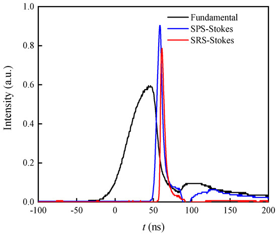
Figure 2.
The pulse evolutions for the fundamental, SPS-Stokes, and SRS-Stokes waves. SPS: stimulated polariton scattering; SRS: stimulated Raman scattering.
The tuning characteristics of the SRS-Stokes wave are illustrated as the round dots in Figure 3a. λS and λR represent the wavelengths of the SPS-Stokes and SRS-Stokes waves, respectively. Setting the pump power at 5.4 W and the pulse repetition frequency at 7 kHz, when the external angle θe was tuned from 2.3° to 5.6°, the wavelength of the SPS-Stokes wave was discontinuously tuned from 1080.13 nm to 1081.60 nm, from 1082.72 nm to 1083.73 nm, and from 1085.12 nm to 1087.49 nm. The wavelength of the SRS-Stokes wave was discontinuously tuned from 1112.08 nm to 1113.64 nm, from 1114.94 nm to 1115.77 nm, and from 1117.37 nm to 1119.92 nm. The maximum output power appeared at 1118.86 nm (the corresponding wavelength of the SPS-Stokes wave was 1086.46 nm). The reason why there were gaps in the tuning range is that the crystal’s absorption for THz wave became very large near the transversal optical (TO) modes. This phenomenon is very familiar for Stokes lasers and terahertz parametric oscillators based on SPS [17,24,25,27,30]. For a given θe of 4.3°, the input-output characteristic was investigated, and the corresponding output wavelength of the SRS-Stokes wave was 1118.86 nm. As the laser diode pumping power increased from 3.5 W to 6.0 W, the measured average output powers of the SPS-Stokes, SRS-Stokes, and fundamental waves are illustrated as the round dots in Figure 3b. The average output power of the SRS-Stokes wave reached 734 mW when the laser diode pumping power was 6.0 W. The corresponding conversion efficiency from diode to SRS-Stokes wave was 12.2%. The solid lines in Figure 3 are the simulation results, which are discussed in the next section.
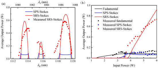
Figure 3.
(a) Output power of the SRS-Stokes wave as a function of wavelength. (b) Output powers as functions of pump power.
The M2 factor was measured by a beam quality analyzer (THORLABS, M2MS). When the pumping power was 6.0 W, the SRS-Stokes wavelength was 1119.12 nm, the distance between the output coupler and the detector was 8.0 cm, the measured M2 factor of the SRS-Stokes wave was 1.2 on both horizontal and vertical directions, the M2 factor of the SPS-Stokes wave was 1.3 on the horizontal direction and 1.4 on vertical direction, and the M2 of the depleted fundamental wave was 2.0 on the horizontal direction and 1.9 on vertical direction. The increase of the beam quality from the fundamental wave to the SRS-Stokes wave was caused by the beam clean-up effect [17].
3. Theoretical Simulation
The fundamental, SPS-Stokes, and THz waves in the SPS process follow the energy conservation law and the momentum conservation law
where ωf, ωS, and ωT are the angular frequencies of the fundamental, SPS-Stokes, and THz waves, respectively, and kf, kS, and kT are the wave vectors of the three waves, respectively. Due to the very large refractive index of the nonlinear crystal in the THz region, only the noncollinear phase-matching can be achieved, as shown in Figure 4. By changing the phase-matching angle θ, the wavelength of the SPS-Stokes wave can be tuned within a specific range.
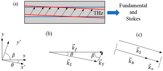
Figure 4.
(a) Interaction area of the SPS process, (b) Noncollinear phase-matching in the SPS process, (c) Collinear SRS process.
As shown in Figure 4a,b, the fundamental wave propagates along the x-axis, the THz wave propagates along the y′-axis, the SPS-Stokes wave propagates along the x′-axis. The angle between kf and kS is noted as θ. Generally, θ is very small (around a few degrees), while β can be 60° or larger, which causes the spatial separation of the THz wave. As shown in Figure 4c, the SRS-Stokes wave propagates along x′-direction in the collinear SRS process.
Under slowly varying amplitude approximation, the coupled wave equations of the noncollinear phase-matching SPS process are expressed as [31,32]:
where αf, αS, and αT are the absorption coefficients of KTP crystal for the fundamental, SPS-Stokes, and THz waves. For most of the nonlinear crystals employed for SPS, αf and αS are so small compared with αT that they can be neglected. The gain coefficients (m = f, S, T) correspond to the second-order nonlinear coefficients for the parametric process, and (m = f, S, T) are the gain coefficients corresponding to the third-order Raman process. To be clarified, since the angle between kf and kS is so small, the SPS-Stokes wave is considered propagating along the x-direction. The coefficients in Equations (3)–(5) are expressed as [33,34,35]:
where nm (m = f, S, T) are the refractive indices of KTP crystal for the fundamental, SPS-Stokes, and THz waves, respectively, c and ε0 denote the light speed and permittivity in a vacuum. d33 is the second-order nonlinear coefficient of the nonlinear crystal. 4d33 corresponds to the electronic polarization, and dQjχQj corresponds to the ionic polarization. ωjTO, Sj, and ΓjTO are the eigenfrequency, oscillator strength, and the damping coefficient of the jth transversal optical (TO) mode, respectively [36]. ħ is the reduced Planck constant, denotes the Bose distribution function [15]. (S33/LΔΩ)j denotes the spontaneous Raman scattering efficiency [15]. ε∞ denotes the high-frequency dielectric constant. All the coefficients in Equations (6)–(10) are frequency-dependent. For convenience, the subscript m = f, S, T, R of all the appeared symbols in the rest part of this paper is corresponding to the parameters and variables of the fundamental, SPS-Stokes, THz, and SRS-Stokes waves, respectively, if not specifically declared.
According to Ref. [37], in the intracavity SPS oscillator, although the intensities of the THz waves that propagate along y′ and −y′ directions increase individually, the total intensity distribution of the THz wave on the yOz plane can be considered uniform approximately. Thus, the coupled wave equations of the intracavity SPS process can be reformed as [37]:
where
where D is the diameter of the fundamental and Stokes beams.
Combining the coupled wave equations for the SPS process with those for the Raman process [38], the coupled wave equations for the cascaded SPS-SRS process can be written as
where IR is the intensity of the cascaded SRS-Stokes wave, which is generated from the SPS-Stokes wave, corresponding to the 268 cm−1 Raman shift of the KTP crystal. GRP and GRS are the Raman gain coefficients of the SRS process.
Equations (17)–(19) describe the entire cascaded SPS-SRS converting process in the nonlinear crystal. Using Equations (17)–(19) and following the method proposed by Degnan [39], the rate equations of the Q-switched intracavity SPS-SRS laser can be obtained:
where σ is the stimulated emission cross-section of the Nd:YAG gain medium, ϕm (m = f, S, R) are the photon densities of the fundamental, SPS-Stokes, and SRS-Stokes waves, respectively. ωR and IR are the angular frequency and intensity of the SRS-Stokes wave, n denotes the population inversion density in the laser medium, γ is the inversion reduction factor of the laser gain medium, la and lc are the lengths of the laser gain medium and the nonlinear crystal, respectively, trm (m = f, S, R) are the roundtrip periods for the fundamental, SPS-Stokes, and SRS-Stokes waves, respectively. Lm (m = f, S, R) denote the roundtrip losses of the three waves. Rm (m = f, S, R) denote the reflectivities of the output couplers for the three waves, respectively. For diode-pumped Q-switched lasers, the relation between the initial population inversion density and the pump power is [40,41,42]:
where τ is the upper-level lifetime of the laser medium, Pin is the input pump power, ωP and αP are the angular frequency and absorption coefficient of the laser gain medium for the pump light, fa is the Boltzmann occupation factor (for Nd:YAG, fa = 0.41 [37]), f is the pulse repetition frequency. The population inversion density threshold can be expressed as
The output parameters of the Q-switched intracavity SPS-SRS laser are
where Pm-max and Em (m = f, S, R) are the output peak powers and pulse energies of the fundamental, SPS-Stokes, and SRS-Stokes waves, respectively, ϕm-max (m = f, S, R) are the peak values of the photon densities ϕm (m = f, S, R).
The SPS process is mainly influenced by the TO modes with A1 symmetry. Table 1 demonstrates some parameters of A1 modes under 300 cm−1 of the KTP crystal [43]. Together with these parameters and Raman scattering cross-sections estimated from Refs. [44,45,46,47,48], the absorption coefficient and refractive index of the KTP crystal in the THz region could be obtained, along with the SPS gain coefficients and (m = f, S, T), as illustrated in Figure 5, where νT is the wavenumber of the polariton in a vacuum. When the beam diameter D is set to be 0.6 mm, the calculated SPS coefficient GS as a function of νT is shown in Figure 6.

Table 1.
Parameters of A1 modes under 300 cm−1 of KTiOPO4 (KTP).
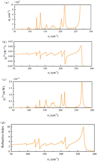
Figure 5.
Calculated parameters of KTP crystal. (a) The absorption coefficient αT for the terahertz wave. (b) Second-order gain coefficient . (c) Third-order gain coefficient . (d) Refractive index in terahertz region. KTP: KTiOPO4; νT: wavenumber of the terahertz wave.
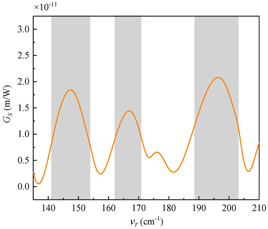
Figure 6.
Gain coefficient GS as a function of the polariton wave number, and the SPS effect permitted areas are roughly marked by grey rectangles.
It can be seen that the third-order gain coefficient and the absorption coefficient αT are very large when the polariton frequency approaches the eigenfrequencies of the TO modes, while the second-order gain coefficient rapidly varies around the eigenfrequencies of the TO modes. This indicates that the SPS effect occurs only when the polariton frequency is far from the eigenfrequencies of the TO modes, causing gaps in the SPS-Stokes wave tuning range, as instructed in the experiment section. The appearance of the gaps can be explained more clearly by the behavior of the gain coefficients Gf and GS of the SPS process in Equations (11) and (12). The SPS effect can only be observed in the grey regions in Figure 6, where GS becomes relatively large. When the polariton wave number is 196 cm−1, the gain coefficient GS is maximum (2.10 × 10⁻¹¹ m/W). With the gain coefficients Gf and GS, the pulse evolution of the SPS-SRS process could be obtained by numerically solving the rate equations. Table 2 gives the parameters used in the simulation.
Table 2.
Parameters in the rate equations. LD: laser diode; SPS: stimulated polariton scattering; SRS: stimulated Raman scattering.
Figure 7 shows the simulation results for the pulse evolutions of the fundamental, SPS-Stokes, and SRS-Stokes photon densities. They are obtained when the pumping power is 5.4 W and the polariton wave number is 196 cm−1. The corresponding wavelengths of the SPS-Stokes and SRS-Stokes waves are 1086.53 nm and 1119.12 nm, respectively, where the SPS gain coefficients Gf and Gs have reached their maximums of 2.15 × 10⁻¹¹ m/W and 2.10 × 10⁻¹¹ m/W, respectively. During the SPS and SRS processes, the fundamental wave appears firstly, and the SPS-Stokes wave slowly accumulates as the fundamental wave photon density rises. Then, the fundamental wave is quickly depleted, while the SPS-Stokes pulse is generated. The SRS-Stokes pulse appears the last when the SPS-Stokes wave photon density drops quickly. These simulation results are similar to the experimental results shown in Figure 2.
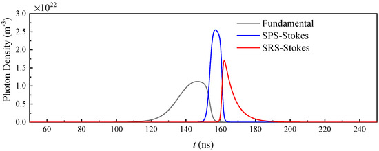
Figure 7.
Calculated pulse evolutions of the SPS-SRS process.
The simulation results for the output powers of the SPS-Stokes and SRS-Stokes waves as functions of wavelengths are illustrated as the solid lines in Figure 3a, along with the measured data in the experiment. There are two gaps in the tuning range. The gap between 1113.64 nm and 1114.94 nm corresponds to the TO mode νTO = 154 cm−1, the gap between 1115.77 nm and 1117.37 nm corresponds to the TO modes νTO = 172 cm−1, 178 cm−1. The simulation results of the input-output characteristics are illustrated as the solid lines in Figure 3b. It can be seen from Figure 3 that the simulation results, including the laser output range, peak wavelength corresponding to the maximum output power, the gaps in the tuning range, the input-output characteristics, are in agreement with the measured experiment data, which proves the effectivity of the simulation model and the calculations for the parameters of the KTP crystal. But there are still some differences between the simulation results and the experimental data. The reasons may be as follows. First, in the experiment, the intensities of the laser beams have nearly Gaussian distribution, rather than uniform plane wave distribution, which is assumed in the simulation model. In the experiment, the laser power density in the central part near the axis is larger than that in the outer part. It means that, with the same photon density, the central part of the laser beam has a nonlinear effect more easily than the situation in the simulation, so the calculated threshold is slightly higher. Second, the variation of the thermal effect with the pumping power is not considered in the numerical simulation, and this is the reason why the slope efficiency of the measured SRS-Stokes output power is unstable, unlike the simulation results.
4. Conclusions
The characteristics of a tunable Stokes laser based on KTP crystal have been investigated. This laser combines the SPS and SRS effects to expand the available spectral range. When the Q-switched fundamental wave frequency is 1064 nm, the SRS-Stokes wavelength can be discontinuously tuned in three bands of 1112.08–1113.64 nm, 1114.94–1115.77 nm, and 1117.37–1119.92 nm. The maximum output power is 734 mW at 1118.86 nm. It appears when the phase-matching angle θe is 4.3°, the pulse repetition frequency (PRF) is 7 kHz, and the pumping power is 6.0 W. Considering 9 TO A1 modes under 300 cm−1 of KTP crystal, its second-order gain coefficients g(2), third-order gain coefficients g(3), and the absorption coefficient αT as functions of wavelength are calculated. The properties of the SPS-SRS laser are theoretically simulated using the model of rate equations. The simulation results of the laser tuning and input-output characteristics are in agreement with the experimental results approximately. The reasons why there are some differences between the theoretical and experimental results are analyzed.
Author Contributions
Conceptualization, Z.W. and X.Z.; methodology, Z.W. and X.Z.; investigation, Z.W.; resources, N.M. and Q.G.; writing—original draft preparation, Z.W.; writing—review and editing, Z.C., Z.L. and X.C.; visualization, Z.Q. and N.M. All authors have read and agreed to the published version of the manuscript.
Funding
This research was funded by the National Natural Science Foundation of China (grant numbers 61475087, 61775122) and the Key Technology Research and Development Program of Shandong Province (grant number 2019JMRH0111).
Conflicts of Interest
The authors declare no conflict of interest.
References
- Ahmed, F. Laser damage threshold of KTiOPO4. Appl. Opt. 1989, 28, 119–122. [Google Scholar] [CrossRef]
- Coetzee, R.S.; Thilmann, N.; Zukauskas, A.; Canalias, C.; Pasiskevicius, V. Nanosecond laser induced damage thresholds in KTiOPO4 and Rb:KTiOPO4 at 1 μm and 2 μm. Opt. Mater. Express 2015, 5, 2090–2095. [Google Scholar] [CrossRef]
- Shoji, I.; Kondo, T.; Kitamoto, A.; Shirane, M.; Ito, R. Absolute scale of second-order nonlinear-optical coefficients. J. Opt. Soc. Am. B 1997, 14, 2268–2294. [Google Scholar] [CrossRef]
- Honea, E.C.; Ebbers, C.A.; Beach, R.J.; Speth, J.A.; Skidmore, J.A.; Emanuel, M.A.; Payne, S.A. Analysis of an intracavity-doubled diode-pumped Q-switched Nd:YAG laser producing more than 100 W of power at 0.532 μm. Opt. Lett. 1998, 23, 1203–1205. [Google Scholar] [CrossRef] [PubMed]
- Albrecht, H.; Balmbois, F.; Lupinski, D.; Georges, P.; Brun, A. Intracavity testing of KTiOPO4 crystals for second-harmonic generation at 532 nm. Appl. Opt. 1999, 38, 2536–2539. [Google Scholar] [CrossRef] [PubMed]
- Brown, A.J.; Bowers, M.S.; Kangas, K.W.; Fisher, C.H. High-energy, high-efficiency second-harmonic generation of 1064 nm radiation in KTP. Opt. Lett. 1992, 17, 109–111. [Google Scholar] [CrossRef] [PubMed]
- Stolzenberger, R.A.; Hsu, C.C.; Peyghambarian, N.; Reid, J.J.; Morgan, R.A. Type II sum frequency generation in flux and hydrothermally grown KTP at 1.319 and 1.338 μm. IEEE Photonics Tech. Lett. 1989, 1, 446–448. [Google Scholar] [CrossRef]
- Driscoll, T.A.; Hoffman, H.J.; Stone, R.E. Efficient second-harmonic generation in KTP crystals. J. Opt. Soc. Am. B 1986, 3, 683–686. [Google Scholar] [CrossRef]
- Huisken, F.; Kaloudis, M.; Marquez, J.; Chuzavkov, Y.L.; Orlov, S.N.; Polivanov, Y.N.; Smirnov, V.V. Single-mode KTiOPO4 optical parametric oscillator. Opt. Lett. 1995, 20, 2306–2308. [Google Scholar]
- Bai, F.; Wang, Q.P.; Liu, Z.J.; Zhang, X.Y.; Wan, X.B.; Lan, W.X.; Shen, H.B.; Zhang, S.S.; Jin, G.F. 1.8 μm optical parametric oscillator based on KTiOPO4. Laser Phys. 2012, 22, 1797–1802. [Google Scholar] [CrossRef]
- Tiihonen, M.; Pasiskevicius, V.; Laurell, F. Noncollinear double-ring optical parametric oscillators with periodically poled KTiOPO4. Opt. Express 2004, 12, 5526–5532. [Google Scholar] [CrossRef]
- Huang, H.T.; He, J.L.; Liu, S.D.; Yang, J.F.; Zhang, B.T.; Liu, F.Q. Efficient generation of 1096 nm and 1572 nm by simultaneous stimulated Raman scattering and optical parametric oscillation in one KTiOPO4 crystal. Appl. Phys. B 2011, 103, 129–135. [Google Scholar] [CrossRef]
- Pasiskevicius, V.; Canalias, C.; Laurell, F. Highly efficient stimulated Raman scattering of picosecond pulses in KTiOPO4. Appl. Phys. Lett. 2006, 88, 041110. [Google Scholar] [CrossRef]
- Su, F.F.; Zhang, X.Y.; Wang, W.T.; Cong, Z.H.; Shi, M.; Yang, X.Q.; Kong, W.J.; Ma, L.L.; Wu, W.D. High-efficient diode-pumped actively Q-switched Nd:YAG/KTP Raman laser at 1096 nm wavelength. Opt. Commun. 2013, 305, 201–203. [Google Scholar] [CrossRef]
- Kawase, K.; Shikata, J.; Ito, H. THz wave parametric source. J. Phys. D 2002, 35, R1–R14. [Google Scholar] [CrossRef]
- Shikata, J.; Kawase, K.; Karino, K.; Taniuchi, T.; Ito, H. Tunable THz-wave parametric oscillators using LiNbO3 and MgO:LiNbO3 crystals. IEEE Trans. Microw. Theory Tech. 2000, 48, 653–661. [Google Scholar] [CrossRef]
- Gao, F.L.; Zhang, X.Y.; Cong, Z.H.; Liu, Z.J.; Chen, X.H.; Qin, Z.G.; Wang, P.; Xu, J.J.; Wang, Z.C.; Ming, N. Tunable Stokes laser based on the cascaded stimulated polariton scattering and stimulated Raman scattering in RbTiOPO4 crystal. Opt. Lett. 2020, 45, 861–864. [Google Scholar] [CrossRef] [PubMed]
- Henry, C.H.; Hopfield, J.J. Raman scattering by polaritons. Phys. Rev. Lett. 1965, 15, 964–966. [Google Scholar] [CrossRef]
- Kawase, K.; Sato, M.; Taniuchi, T.; Ito, H. Coherent tunable THz wave generation from LiNbO3 with monolithic grating coupler. Appl. Phys. Lett. 1996, 68, 2483–2485. [Google Scholar] [CrossRef]
- Lee, A.; He, Y.B.; Pask, H. Frequency-tunable THz source based on stimulated polariton scattering in Mg:LiNbO3. IEEE J. Quantum Electron. 2013, 49, 357–364. [Google Scholar] [CrossRef]
- Edwards, T.J.; Walsh, D.; Spurr, M.B.; Rae, C.F.; Dunn, M.H.; Browne, P.G. Compact source of continuously and widely-tunable THz radiation. Opt. Express 2006, 14, 1582–1589. [Google Scholar] [CrossRef] [PubMed]
- Yan, C.; Wang, Y.Y.; Xu, D.G.; Xu, W.T.; Liu, P.X.; Yan, D.X.; Duan, P.; Zhong, K.; Shi, W.; Yao, J.Q. Green laser induced terahertz tuning range expanding in KTiOPO4 THz parametric oscillator. Appl. Phys. Lett. 2016, 108, 011107. [Google Scholar] [CrossRef]
- Wu, M.H.; Tsai, W.C.; Chiu, Y.C.; Huang, Y.C. Generation of similar to 100 kW narrow-line far-infrared radiation from a KTP off-axis THz parametric oscillator. Optica 2019, 6, 723–730. [Google Scholar] [CrossRef]
- Wang, W.T.; Cong, Z.H.; Chen, X.H.; Zhang, X.Y.; Qin, Z.G.; Tang, G.Q.; Li, N.; Wang, C.; Lu, Q.M. Terahertz parametric oscillator based on KTiOPO4 crystal. Opt. Lett. 2014, 39, 3706–3709. [Google Scholar] [CrossRef]
- Gao, F.L.; Zhang, X.Y.; Cong, Z.H.; Liu, Z.J.; Chen, X.H.; Qin, Z.G.; Wang, P.; Xu, J.J.; Wang, Z.C.; Ming, N. Enhancement of intracavity terahertz parametric source power by adopting diode-side-pumped configuration based on KTiOPO4 crystal. Crystals 2019, 9, 666. [Google Scholar] [CrossRef]
- Wu, M.H.; Chiu, Y.C.; Wang, T.D.; Zhao, G.; Zukauskas, A.; Laurell, F.; Huang, Y.C. Terahertz parametric generation and amplification from potassium titanyl phosphate in comparison with lithium niobate and lithium tantalate. Opt. Express 2016, 24, 25964–25973. [Google Scholar] [CrossRef] [PubMed]
- Jiang, S.Q.; Chen, X.H.; Cong, Z.H.; Zhang, X.Y.; Qin, Z.G.; Liu, Z.J.; Wang, W.T.; Li, N.; Fu, Q.; Lu, Q.M.; et al. Tunable Stokes laser generation based on the stimulated polariton scattering in KTiOPO4 crystal. Opt. Express 2015, 23, 20187–20194. [Google Scholar] [CrossRef]
- Ammann, E.O. Simultaneous stimulated Raman scattering and optical frequency mixing in lithium iodate. Appl. Phys. Lett. 1979, 34, 838–840. [Google Scholar] [CrossRef]
- Chang, Y.T.; Chang, H.L.; Su, K.W.; Chen, Y.F. High-efficiency Q-switched dual-wavelength emission at 1176 and 559 nm with intracavity Raman and sum-frequency generation. Opt. Express 2009, 17, 11892–11897. [Google Scholar] [CrossRef]
- Zang, J.; Cong, Z.H.; Chen, X.H.; Zhang, X.Y.; Qin, Z.G.; Liu, Z.J.; Lu, J.R.; Wu, D.; Fu, Q.; Jiang, S.Q.; et al. Tunable KTA Stokes laser based on stimulated polariton scattering and its intracavity frequency doubling. Opt. Express 2016, 24, 7558–7565. [Google Scholar] [CrossRef]
- Henry, C.H.; Garrett, C.G. Theory of parametric gain near a lattice resonance. Phys. Rev. 1968, 171, 1058–1064. [Google Scholar] [CrossRef]
- Schwarz, U.T.; Maier, M. Damping mechanisms of phonon polaritons, exploited by stimulated Raman gain measurements. Phys. Rev. B 1998, 58, 766–775. [Google Scholar] [CrossRef]
- Kleinman, D.A. Nonlinear dielectric polarization in optical media. Phys. Rev. 1962, 126, 1977–1979. [Google Scholar] [CrossRef]
- Boyd, G.D.; Bridges, T.J.; Pollack, M.A.; Turner, E.H. Microwave nonlinear susceptibilities due to electronic and ionic anharmonicities in acentric crystals. Phys. Rev. Lett. 1971, 26, 387–390. [Google Scholar] [CrossRef]
- Jia, C.Y.; Zhang, X.Y.; Cong, Z.H.; Liu, Z.J.; Chen, X.H.; Qin, Z.G.; Zang, J.; Gao, F.L.; Wang, P.; Jiao, Y.; et al. Theoretical and experimental study on a large energy potassium titanyl phosphate THz parametric source. Opt. Laser Technol. 2020, 121, 105817. [Google Scholar] [CrossRef]
- Barker, A.S.; Loudon, R. Dielectric properties and optical phonons in LiNbO3. Phys. Rev. 1967, 158, 433–445. [Google Scholar] [CrossRef]
- Wang, P.; Zhang, X.Y.; Cong, Z.H.; Liu, Z.J.; Chen, X.H.; Qin, Z.G.; Gao, F.L.; Xu, J.J.; Wang, Z.C.; Ming, N. Modeling of intracavity-pumped Q-switched THz parametric oscillators based on stimulated polariton scattering. Opt. Express 2020, 28, 6966–6980. [Google Scholar] [CrossRef]
- Ding, S.H.; Zhang, X.Y.; Wang, Q.P.; Su, F.F.; Li, S.T.; Fan, S.Z.; Liu, Z.J.; Chang, J.; Zhang, S.S.; Wang, S.M.; et al. Theoretical and experimental research on the multi-frequency Raman converter with KGd(WO4)2 crystal. Opt. Express 2005, 13, 10120–10128. [Google Scholar] [CrossRef]
- Degnan, J.J. Theory of the Optimally Coupled Q-Switched Laser. IEEE J. Quantum Electron. 1989, 25, 214–220. [Google Scholar] [CrossRef]
- Lan, Y.P.; Chen, Y.F.; Wang, S.C. Repetition-rate dependence of thermal loading in diode-end-pumped Q-switched lasers: Influence of energy-transfer upconversion. Appl. Phys. B 2000, 71, 27–31. [Google Scholar] [CrossRef]
- Fan, T.Y.; Byer, R.L. Diode laser-pumped solid-state lasers. IEEE J. Quantum Electron. 1988, 24, 895–912. [Google Scholar] [CrossRef]
- Chen, Y.F.; Lan, Y.P.; Wang, S.C. Modeling of diode-end-pumped Q-switched solid-state lasers: Influence of energy-transfer upconversion. J. Opt. Soc. Am. B 2002, 19, 1558–1563. [Google Scholar] [CrossRef]
- Kugel, G.E.; Bréhat, F.; Wyncke, B.; Fontana, M.D.; Marnier, G.; Carabatos-Nedelect, C.; Mangin, J. The vibrational spectrum of a KTiOPO4 single crystal studied by Raman and infrared reflectivity spectroscopy. J. Phys. C 1988, 21, 5565–5583. [Google Scholar] [CrossRef]
- Chu, H.W.; Yang, K.J.; Li, T.; Zhao, S.Z.; Li, Y.F.; Li, D.C.; Li, G.Q.; Zhao, J.; Qiao, W.C. Simultaneous Stokes and anti-Stokes lines operation within a Yb:YAG laser at 1050 nm. IEEE. Photonics Tech. Lett. 2014, 26, 2369–2371. [Google Scholar] [CrossRef]
- Johnston, W.D.; Kaminow, I.P. Contributions to optical nonlinearity in GaAs as determined from Raman scattering efficiencies. Phys. Rev. 1969, 188, 1209–1211. [Google Scholar] [CrossRef]
- Massey, G.A.; Loehr, T.M.; Willis, L.J.; Johnson, J.C. Raman and electrooptic properties of potassium titanate phosphate. Appl. Opt. 1980, 19, 4136–4137. [Google Scholar] [CrossRef] [PubMed]
- Jang, H.; Strömqvist, G.; Pasiskevicius, V.; Canalias, C. Control of forward stimulated polariton scattering in periodically-poled KTP crystals. Opt. Express 2013, 21, 27277–27283. [Google Scholar] [CrossRef]
- Furusawa, S.; Hayasi, H.; Ishibashi, Y.; Miyamoto, A.; Sasaki, T. Raman scattering study of KTiOPO4 (KTP) single crystal. J. Phys. Soc. Jpn. 1991, 60, 2470–2474. [Google Scholar] [CrossRef]
Publisher’s Note: MDPI stays neutral with regard to jurisdictional claims in published maps and institutional affiliations. |
© 2020 by the authors. Licensee MDPI, Basel, Switzerland. This article is an open access article distributed under the terms and conditions of the Creative Commons Attribution (CC BY) license (http://creativecommons.org/licenses/by/4.0/).